EP1233643A2 - Miniature microphone with improved wind-protection - Google Patents
Miniature microphone with improved wind-protection Download PDFInfo
- Publication number
- EP1233643A2 EP1233643A2 EP02450003A EP02450003A EP1233643A2 EP 1233643 A2 EP1233643 A2 EP 1233643A2 EP 02450003 A EP02450003 A EP 02450003A EP 02450003 A EP02450003 A EP 02450003A EP 1233643 A2 EP1233643 A2 EP 1233643A2
- Authority
- EP
- European Patent Office
- Prior art keywords
- microphone
- volume
- capsule
- housing
- inlet openings
- Prior art date
- Legal status (The legal status is an assumption and is not a legal conclusion. Google has not performed a legal analysis and makes no representation as to the accuracy of the status listed.)
- Withdrawn
Links
Images

Classifications
-
- H—ELECTRICITY
- H04—ELECTRIC COMMUNICATION TECHNIQUE
- H04R—LOUDSPEAKERS, MICROPHONES, GRAMOPHONE PICK-UPS OR LIKE ACOUSTIC ELECTROMECHANICAL TRANSDUCERS; DEAF-AID SETS; PUBLIC ADDRESS SYSTEMS
- H04R1/00—Details of transducers, loudspeakers or microphones
- H04R1/08—Mouthpieces; Microphones; Attachments therefor
- H04R1/083—Special constructions of mouthpieces
- H04R1/086—Protective screens, e.g. all weather or wind screens
-
- H—ELECTRICITY
- H04—ELECTRIC COMMUNICATION TECHNIQUE
- H04R—LOUDSPEAKERS, MICROPHONES, GRAMOPHONE PICK-UPS OR LIKE ACOUSTIC ELECTROMECHANICAL TRANSDUCERS; DEAF-AID SETS; PUBLIC ADDRESS SYSTEMS
- H04R1/00—Details of transducers, loudspeakers or microphones
- H04R1/20—Arrangements for obtaining desired frequency or directional characteristics
- H04R1/32—Arrangements for obtaining desired frequency or directional characteristics for obtaining desired directional characteristic only
- H04R1/34—Arrangements for obtaining desired frequency or directional characteristics for obtaining desired directional characteristic only by using a single transducer with sound reflecting, diffracting, directing or guiding means
- H04R1/38—Arrangements for obtaining desired frequency or directional characteristics for obtaining desired directional characteristic only by using a single transducer with sound reflecting, diffracting, directing or guiding means in which sound waves act upon both sides of a diaphragm and incorporating acoustic phase-shifting means, e.g. pressure-gradient microphone
-
- H—ELECTRICITY
- H04—ELECTRIC COMMUNICATION TECHNIQUE
- H04R—LOUDSPEAKERS, MICROPHONES, GRAMOPHONE PICK-UPS OR LIKE ACOUSTIC ELECTROMECHANICAL TRANSDUCERS; DEAF-AID SETS; PUBLIC ADDRESS SYSTEMS
- H04R2410/00—Microphones
- H04R2410/07—Mechanical or electrical reduction of wind noise generated by wind passing a microphone
Definitions
- the present invention relates to a miniature microphone with a in a microphone housing housed microphone capsule with front sound inlets leading to one front volume, with rear sound inlet openings leading to a rear Lead volume and with a connection volume, thus a pressure gradient receiver, with improved wind protection or pop protection.
- Microphone capsules regardless of their physical mode of operation, can act as pressure receivers or built up as a pressure gradient receiver.
- the two capsule types differ from each other mainly in the directivity that can be achieved.
- the directional characteristic of a microphone capsule is dependent on the sensitivity of the capsule defined by the angle of objection, and can be considered a spherical, kidney, hypemic, Supercardioid or figure-eight polar pattern with associated polar diagram to be discribed.
- pressure gradient receivers In order to achieve a one-sided directional characteristic, so-called pressure gradient receivers must be used be built. They not only have a front sound inlet opening, but also a second one, which can be realized either on the side or at the back with whose help the membrane of the microphone capsule is exposed to a pressure difference.
- the Acoustic tuning of a pressure gradient capsule is carried out by a specialist known acoustic means, so that both the desired directional characteristic, as well as a desired frequency response is achieved.
- the microphone capsules have a pronounced one-sided directional characteristic because of their noise-reducing properties are required, they have compared to capsules spherical polar pattern also has a major disadvantage compared to wind or so-called pop noises. Pop noises arise when inexperienced pronunciation of Explosive consonants like "P" or "B".
- the damping of the wind noise takes place according to the known prior art with the help of different types of microphone baskets.
- the microphone baskets which also serve as mechanical protection of the microphone capsule, with various porous materials filled. This is mainly done using open-cell foams, which either inserted into the inside of the microphone grille basket or as a wind protection cap on the Microphone grill cap are placed.
- the effectiveness of such wind protection devices is on the one hand from the foam density and on the other hand from the distance to the microphone capsule dependent.
- a denser foam generally provides better wind protection, however also a loss of sensitivity of the microphone at higher frequencies. Behaves similarly the distance from the microphone capsule to be protected. A bigger one Distance means better protection, but with the disadvantage that the microphone can no longer be kept inconspicuously small.
- Miniature microphones which are mainly on the human body, either through Buckle up, clip on, stick on or put on are used for the purpose of Reduction of wind or pop sensitivity executed as a pressure receiver.
- the wind sensitivity of the microphone can be kept low, but on the other hand are also undesirable due to the spherical polar pattern of the microphone Receive and transmit noise from the acoustic environment of the microphone.
- the use of miniature microphones with one-sided directional characteristic was until now particularly difficult due to their sensitivity to wind. They absolutely had to Wear an outer protective cap made of foam.
- the aim of the invention is the integration of miniature microphones, which are made from dynamic or electret capsules with one-sided directional characteristic in components with low Dimensions (e.g. microphone arm of a headset) with the special feature of an integrated To allow wind protection without the structure of the microphone complicated and expensive shape.
- these objectives are achieved in that, in the installed state Microphone capsule with the help of narrow channels, which are inside the microphone housing be carried out, an acoustic connection between the front and rear side the microphone capsule is realized.
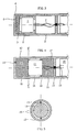
- Fig. 2 is a diagram for explaining the problem underlying the invention
- 3 shows a small microphone according to the prior art
- 4 shows a cross section through an inventive microphone
- 5 shows a section along the line VV of FIG. 4th
- Fig. 1 shows, shown by the wavy lines, a turbulent Sound field in which there is a microphone capsule with two sound inlet openings a and b located.
- P0 is the static air pressure, the intensity changes of which are so slow that they can be neglected.
- Two vectors Pa and Pb are shown on the tip of the vector P0.
- the diaphragm driving force at one Pressure gradient capsule can be much larger than a pressure capsule. And This is because in a turbulent air pressure field, the pressure differences between two neighboring points can become significantly larger than the air pressure at one Point in the same turbulent air pressure field over time, as can be seen from Fig. 2.
- the microphones that are built with such microphone capsules are special is sensitive to wind noise and its damping is usually only with realizable with great effort.
- the pressure gradient receiver executed microphone capsule 1 two (not shown separately) sound inlet openings has that but in the rear volume 7 with the rear sound entry openings 3 no Foam is inserted and that the capsule holder 2 the front volume of rear volume (acoustically) completely isolated. So you save a lot of manufacturing costs, but increases the wind sensitivity of the microphone, because only completely identical sound paths do not lead to any additional pressure differences on the membrane of the capsule.
- FIGS. 4 and 5 A solution according to the invention is shown in FIGS. 4 and 5: a conventional pressure gradient capsule 11 with one-sided directional characteristic is usually in one cylindrical housing 12, which can also be designed with a different shape, and is held by knobs or webs 13 which protrude inwards from the housing wall.
- a conventional pressure gradient capsule 11 with one-sided directional characteristic is usually in one cylindrical housing 12, which can also be designed with a different shape, and is held by knobs or webs 13 which protrude inwards from the housing wall.
- front sound inlet openings 14 and rear sound inlet openings 15 provided in the housing 12 is a front through the inserted capsule 11 Volume 16, a rear volume 17 and a connecting volume connecting the two 18 trained.
- the front volume 16 and the rear volume 17 are each with at least one sound-permeable foam part 19 completely or partially filled.
- the connection volume 18 acts as a calming zone and results in connection with the properties of the foam 19 a very strong damping of wind noise.
- the front sound inlet openings 14 allow the sound to enter the front from the front Volume 16, so that both to the inlet openings (not shown separately) on the Front of the capsule 11 and, by means of the connection volume 18, to the rear Volume 17 and from there to the rear sound inlet openings (not shown separately) on the back of the capsule 11.
- the rear wall of the rear volume 17 is acoustic from the following building structure tightly insulated, in that firstly the volume 17 is kept small and secondly that the microphone housing 12 is closed on the inside and no coupling to other volumes allows. 4, the connecting wires 10 of the microphone capsule 11 can still be seen. They are pulled through an opening and the opening is closed with the help of glue or other elastic material 21 closed, so that the remaining volume 20 of the microphone housing is not acoustically coupled to the volume 17.
- the size of the volumes and the inlet openings is determined using the microphone construction Usually used criteria selected so that the desired shaping of the Frequency response is reached.
- the shape and size of the front volume 16, which is preferred is completely filled with foam 19, is preferably chosen so that its Height (distance between the front of the microphone capsule 11 and the front Sound inlet openings 14) about 1 ⁇ 4 of the smallest wavelength to be transmitted (highest frequency to be transmitted). In this way, one exploits its effect as a resonator and widens the microphone frequency curve at higher frequencies.
- the size of the rear Volume 17 is less critical as long as the openings 15 are close enough to the first Bottom of the capsule 11 are arranged and secondly, their size an uninhibited Allows passage of sound.
- the connection channels, shown as connection volume 18 are preferably about 0.5 to 2 mm wide (radial extension). You can be trained even broader, but this only makes sense in exceptional cases because the microphone gets bigger again.
- volume an empty or with foam or the like. partially or completely filled volume is understood, but at least acoustically essentially is permeable.
Abstract
Description
Die vorliegende Erfindung betrifft ein Miniaturmikrofon mit einer in einem Mikrofongehäuse untergebrachten Mikrofonkapsel mit vorderen Schalleintrittsöffnungen die zu einem vorderen Volumen führen, mit hinteren Schalleintrittsöffnungen die zu einem hinteren Volumen führen und mit einem Verbindungsvolumen, somit einen Druckgradientenempfänger, mit verbessertem Windschutz bzw. Popschutz.The present invention relates to a miniature microphone with a in a microphone housing housed microphone capsule with front sound inlets leading to one front volume, with rear sound inlet openings leading to a rear Lead volume and with a connection volume, thus a pressure gradient receiver, with improved wind protection or pop protection.
Mikrofonkapseln, unabhängig von ihrer physikalischen Arbeitsweise, können als Druckempfänger oder als Druckgradientenempfänger aufgebaut werden. Die zwei Kapseltypen unterscheiden sich voneinander hauptsächlich in der erzielbaren Richtcharakteristik. Die Richtcharakteristik einer Mikrofonkapsel wird als Empfindlichkeit der Kapsel in Abhängigkeit vom Einsprachwinkel definiert, und kann als eine Kugel-, Nieren-, Hypemieren-, Supernieren-, oder achterförmige Richtcharakteristik mit dazugehörigem Polardiagramm beschrieben werden. Druckempfänger, bei denen die Membrane der Kapsel nur von einer Seite angeregt wird, weisen eine kugelförmige Richtcharakteristik auf.Microphone capsules, regardless of their physical mode of operation, can act as pressure receivers or built up as a pressure gradient receiver. The two capsule types differ from each other mainly in the directivity that can be achieved. The The directional characteristic of a microphone capsule is dependent on the sensitivity of the capsule defined by the angle of objection, and can be considered a spherical, kidney, hypemic, Supercardioid or figure-eight polar pattern with associated polar diagram to be discribed. Pressure receivers in which the capsule membrane is only one Side is excited, have a spherical polar pattern.
Um eine einseitige Richtcharakteristik erzielen zu können, müssen sogenannte Druckgradientenempfänger gebaut werden. Sie weisen nicht nur eine vordere Schalleintrittsöffnung, sondern auch eine zweite, die entweder seitlich oder hinten realisiert werden kann, mit deren Hilfe die Membrane der Mikrofonkapsel einer Druckdifferenz ausgesetzt wird. Die akustische Abstimmung einer Druckgradientenkapsel wird von einem Fachmann mit bekannten akustischen Mitteln vorgenommen, so dass sowohl die gewünschte Richtcharakteristik, als auch ein gewünschter Frequenzverlauf erreicht wird.In order to achieve a one-sided directional characteristic, so-called pressure gradient receivers must be used be built. They not only have a front sound inlet opening, but also a second one, which can be realized either on the side or at the back with whose help the membrane of the microphone capsule is exposed to a pressure difference. The Acoustic tuning of a pressure gradient capsule is carried out by a specialist known acoustic means, so that both the desired directional characteristic, as well as a desired frequency response is achieved.
Obwohl die Mikrofonkapseln mit ausgeprägter einseitiger Richtcharakteristik wegen ihrer störschalldämmenden Eigenschaft gefragt sind, weisen sie im Vergleich zu Kapseln mit kugelförmiger Richtcharakteristik auch einen großen Nachteil gegenüber Wind- oder sogenannten Popgeräuschen auf. Popgeräusche entstehen bei ungeübter Aussprache von Explosiven Konsonanten wie "P" oder "B".Although the microphone capsules have a pronounced one-sided directional characteristic because of their noise-reducing properties are required, they have compared to capsules spherical polar pattern also has a major disadvantage compared to wind or so-called pop noises. Pop noises arise when inexperienced pronunciation of Explosive consonants like "P" or "B".
Die Dämpfung der Windgeräusche erfolgt nach bekanntem Stand der Technik mit Hilfe von verschiedenartigen Mikrofonkörben. Dabei werden die Mikrofonkörbe, welche auch als mechanischer Schutz der Mikrofonkapsel dienen, mit verschiedensten porösen Materialien ausgefüllt. Dazu verwendet man hauptsächlich offenporige Schaumstoffe, die entweder ins Innere des Mikrofongitterkorbes eingesetzt, oder als Windschutzkappe auf die Mikrofongitterkappe aufgesetzt werden. Die Wirksamkeit solcher Windschutzvorrichtungen ist einerseits von der Schaumdichte und andererseits vom Abstand zur Mikrofonkapsel abhängig. Ein dichterer Schaumstoff bewirkt generell einen besseren Windschutz, aber auch einen Empfindlichkeitsverlust des Mikrofons bei höheren Frequenzen. Ähnlich verhält es sich mit dem Abstand von der zu schützenden Mikrofonkapsel. Ein größerer Abstand bedeutet einen besseren Schutz, allerdings mit dem Nachteil, dass das Mikrofon nicht mehr unauffällig klein gehalten werden kann.The damping of the wind noise takes place according to the known prior art with the help of different types of microphone baskets. The microphone baskets, which also serve as mechanical protection of the microphone capsule, with various porous materials filled. This is mainly done using open-cell foams, which either inserted into the inside of the microphone grille basket or as a wind protection cap on the Microphone grill cap are placed. The effectiveness of such wind protection devices is on the one hand from the foam density and on the other hand from the distance to the microphone capsule dependent. A denser foam generally provides better wind protection, however also a loss of sensitivity of the microphone at higher frequencies. Behaves similarly the distance from the microphone capsule to be protected. A bigger one Distance means better protection, but with the disadvantage that the microphone can no longer be kept inconspicuously small.
Als Beispiel für die Anwendung von Schutzvorrichtungen gegen das Poppen auf Schaumstoffbasis soll hier die EP 0 130 400 A2 genannt werden. Dabei handelt es sich um einen aus offenporigem Schaumstoff angefertigten Pop- und Windschutz, welcher über das Mikrofongehäuse umgestülpt wird.As an example of the use of protective devices against popping based on foam EP 0 130 400 A2 should be mentioned here. It is a made of open-pore foam pop and wind protection, which over the Microphone housing is turned inside out.
Eine andere Methode ist in der US 4,966,252 A beschrieben. Da wird nicht nur der Kapselbereich des Mikrofons, sondern das ganze Mikrofon in ein zeppelinartiges Windschutzgehäuse eingebaut.Another method is described in US 4,966,252 A. It's not just the capsule area of the microphone, but the entire microphone in a zeppelin-like windbreak housing built-in.
Die DE 298 13 397 U1 beschreibt ebenfalls eine Schaumstoffausführung die über das Mikrofongehäuse gestülpt wird.DE 298 13 397 U1 also describes a foam design which uses the Microphone housing is put over.
Allen drei Beispielen ist gemeinsam, dass sic in ihrer Ausführung kompliziert und teuer sind, und dass sich äußere klimatische Verhältnisse sehr negativ auf die Lebensdauer der Schutzvorrichtungen auswirken.All three examples have in common that they are complicated and expensive to implement and that external climatic conditions have a very negative impact on the life of the Impact protective devices.
Miniaturmikrofone, welche hauptsächlich am menschlichen Körper, entweder durch anschnallen, anstecken, aufkleben oder aufsetzen getragen werden, werden zum Zweck der Verringerung der Wind- oder Popempfindlichkeit als Druckempfänger ausgeführt. Damit kann zwar die Windempfindlichkeit des Mikrofons niedrig gehalten werden, aber andererseits werden durch kugelförmige Richtcharakteristik des Mikrofons auch unerwünschte Störgeräusche aus der akustischen Umgebung des Mikrofons empfangen und weiter übertragen. Dic Anwendung von Miniaturmikrofonen mit einseitiger Richtcharakteristik war bis jetzt durch ihre Windempfindlichkeit besonders erschwert. Sie mußten unbedingt eine Außenschutzkappe aus Schaumstoff tragen. Miniature microphones, which are mainly on the human body, either through Buckle up, clip on, stick on or put on are used for the purpose of Reduction of wind or pop sensitivity executed as a pressure receiver. In order to the wind sensitivity of the microphone can be kept low, but on the other hand are also undesirable due to the spherical polar pattern of the microphone Receive and transmit noise from the acoustic environment of the microphone. The use of miniature microphones with one-sided directional characteristic was until now particularly difficult due to their sensitivity to wind. They absolutely had to Wear an outer protective cap made of foam.
Die Erfindung hat das Ziel, die Integration von Miniaturmikrofonen, welche aus Dynamischen- oder Elektretkapseln mit einseitiger Richtcharakteristik in Bauteilen mit geringen Dimensionen (z.B. Mikrofonarm eines Headsets) mit der Besonderheit eines integrierten Windschutzes zu ermöglichen, ohne den Aufbau des Mikrofons kompliziert und teuer zu gestalten.The aim of the invention is the integration of miniature microphones, which are made from dynamic or electret capsules with one-sided directional characteristic in components with low Dimensions (e.g. microphone arm of a headset) with the special feature of an integrated To allow wind protection without the structure of the microphone complicated and expensive shape.
Erfindungsgemäß werden diese Ziele dadurch erreicht, dass im eingebauten Zustand der Mikrofonkapsel mit Hilfe von engen Kanälen, welche im Inneren des Mikrofongehäuses ausgeführt werden, eine akustische Verbindung zwischen der vorderen und hinteren Seite der Mikrofonkapsel realisiert wird.According to the invention, these objectives are achieved in that, in the installed state Microphone capsule with the help of narrow channels, which are inside the microphone housing be carried out, an acoustic connection between the front and rear side the microphone capsule is realized.
Die Erfindung wird im folgenden anhand der Zeichnung näher beschrieben. Dabei zeigt
die Fig. 1 und die Fig. 2 ein Schema zur Erläuterung der der Erfindung zugrundeliegenden
Problematik,
die Fig. 3 ein Kleinmikrophon gemäß dem Stand der Technik,
die Fig. 4 einen Querschnitt durch ein erfindungsgemäßes Mikrofon und
die Fig. 5 einen Schnitt entlang der Linie V-V der Fig. 4.The invention is described below with reference to the drawing. It shows
1 and Fig. 2 is a diagram for explaining the problem underlying the invention,
3 shows a small microphone according to the prior art,
4 shows a cross section through an inventive microphone and
5 shows a section along the line VV of FIG. 4th
Die der Erfindung zugrundeliegende Problematik wird im Folgenden anhand der Fig. 1 und 2 dargelegt: Fig. 1 zeigt, durch die gewellten Linien dargestellt, ein turbulentes Schallfeld, in dem sich eine Mikrofonkapsel mit zwei Schalleintrittsöffnungen a und b befindet.The problem on which the invention is based is described below with reference to FIG. 1 and 2: Fig. 1 shows, shown by the wavy lines, a turbulent Sound field in which there is a microphone capsule with two sound inlet openings a and b located.
In Fig. 2 sind mit Hilfe eines Vektordiagrammes die Druckverhältnisse in einem turbulenten Schalldruckfeld dargestellt. Dabei haben die einzelnen Vektoren folgende Bedeutung: P0 ist der statische Luftdruck, dessen Intensitätsveränderungen so langsam sind, dass man sie vernachlässigen kann. Auf der Spitze des Vektors P0 sind zwei Vektoren Pa und Pb dargestellt. Die Länge des Vektors P0 ist um den Faktor 105 (=100000) länger als diese beiden Vektoren. Sie repräsentieren die Schalldruckverhältnisse an den Stellen der beiden Schalleintrittsöffnungen a und b der in Fig. 1 dargestellten Mikrofonkapsel. Da die Mikrofonkapscl klein ist, sind die Intensitäten (Längen) der beiden Vektoren Pa und Pb identisch (sie werden auf so einer kurzen Strecke nicht abgeschwächt). Ihre Phasenlagen sind aber, durch die Turbulenz des Schallfeldes bedingt, völlig zufällig. 2 shows the pressure conditions in a turbulent sound pressure field with the aid of a vector diagram. The individual vectors have the following meaning: P0 is the static air pressure, the intensity changes of which are so slow that they can be neglected. Two vectors Pa and Pb are shown on the tip of the vector P0. The length of the vector P0 is longer by a factor of 10 5 (= 100000) than these two vectors. They represent the sound pressure conditions at the locations of the two sound inlet openings a and b of the microphone capsule shown in FIG. 1. Since the microphone capsule is small, the intensities (lengths) of the two vectors Pa and Pb are identical (they are not weakened over such a short distance). However, due to the turbulence of the sound field, their phase positions are completely random.
In Fig. 2 sind zwei Momentaufnahmen dargestellt. Im ersten Fall (ausgezogenen Linien) weist der Vektor Pb einen Phasenwinkel von etwa 45° auf, und die Vektordifferenz, welche als Antriebskraft auf die Membrane der Mikrofonkapsel wirkt, hat eine Intensität von Λ P1. Zu einem anderen Zeitpunkt (strichlierte Linien) weist der Vektor Pb einen Phasenwinkel von etwa 120° auf. Dann ist der Druckunterschied Pa - Pb = Λ P2 größer als die einzelnen Drücke Pa oder Pb.Two snapshots are shown in FIG. In the first case (solid lines) the vector Pb has a phase angle of approximately 45 °, and the vector difference, which acts as a driving force on the membrane of the microphone capsule has an intensity from Λ P1. At another point in time (dashed lines), the vector Pb has one Phase angle of about 120 °. Then the pressure difference Pa - Pb = Λ P2 is greater than the individual pressures Pa or Pb.
Das bedeutet, dass in einer turbulenten Luftdruckumgebung, wie sie beim Auftreten von Wind- oder Popgeräuschen im Regelfall herrscht, die Membranantriebskraft bei einer Druckgradientenkapsel wesentlich größer als bei einer Druckkapsel werden kann. Und zwar deshalb, weil in einem turbulenten Luftdruckfeld die Druckunterschiede zwischen zwei benachbarten Punkten wesentlich größer werden können, als der Luftdruck an einem Punkt im gleichen turbulenten Luftdruckfeld über der Zeit, wie aus Fig. 2 ersichtlich ist. Die Mikrofone, welche mit solchen Mikrofonkapseln aufgebaut werden, sind besonders empfindlich gegenüber Windgeräuschen und deren Dämpfung ist normalerweise nur mit sehr großem Aufwand realisierbar.That means that in a turbulent air pressure environment like the one that occurs There is usually wind or pop noise, the diaphragm driving force at one Pressure gradient capsule can be much larger than a pressure capsule. And This is because in a turbulent air pressure field, the pressure differences between two neighboring points can become significantly larger than the air pressure at one Point in the same turbulent air pressure field over time, as can be seen from Fig. 2. The microphones that are built with such microphone capsules are special is sensitive to wind noise and its damping is usually only with realizable with great effort.
Aus der Fig. 3 ist ein herkömmliches Kleinmikrofon mit einseitiger Richtcharakteristik
gemäß dem Stand der Technik zu sehen. Die Mikrofonkapsel 1 mit einer vorderen und
einer hinteren Schalleintrittsöffnung, die nicht dargestellt sind, ist in einer elastischen, die
Griff- oder Reibgeräusche hemmenden, hohlzylindrischen Kapselhalterung 2 eingebettet.
Dabei sind seitliche Schallöffnungen 3 in das Mikrofongehäuse 4 integriert, die zu einem
hinteren Volumen 7 führen. Auf der vorderen Kapselseite, im vorderen Volumen mit
zugehörigen vorderen Schalleintrittsöffnungen 6 im Mikrofongehäuse 4 wird im Regelfall
ein mehr oder weniger poröser Schaumstoff 5 eingelegt. Seine Aufgabe ist zweifach.
Erstens wird dadurch ein Staubschutz der Kapsel gewährleistet und zweitens versucht man
einen Popschutz zu erreichen.3 is a conventional small microphone with one-sided directional characteristic
according to the state of the art. The microphone capsule 1 with a front and
a rear sound inlet opening, which are not shown, is in an elastic, the
Hollow
Bei der dargestellten Lösung ist zu erkennen, dass die als Druckgradientenempfänger ausgeführte Mikrofonkapsel 1 zwar zwei (nicht extra dargestellte) Schalleintrittsöffnungen hat, dass aber im hinteren Volumen 7 mit den hinteren Schallcintrittsöffnungen 3 kein Schaumstoff eingelegt ist und dass die Kapselhalterung 2 das vordere Volumen vom hinteren Volumen (akustisch) völlig isoliert. So erspart man einiges an Herstellungskosten, steigert aber noch die Windempfindlichkeit des Mikrofons, da nur völlig gleiche Schallwege zu keinen zusätzlichen Druckunterschieden an der Membrane der Kapsel führen. In the solution shown it can be seen that the pressure gradient receiver executed microphone capsule 1 two (not shown separately) sound inlet openings has that but in the rear volume 7 with the rear sound entry openings 3 no Foam is inserted and that the capsule holder 2 the front volume of rear volume (acoustically) completely isolated. So you save a lot of manufacturing costs, but increases the wind sensitivity of the microphone, because only completely identical sound paths do not lead to any additional pressure differences on the membrane of the capsule.
Durch das Fehlen des Schaumstoffes im hinteren Volumen 7 des Mikrofons werden die Druckunterschiede auf der Membrane (gegenüber dem völligen Fehlen von Schaumstoffabdeckungen) vergrößert, und dadurch auch die Wind- oder Popempfindlichkeit.Due to the lack of foam in the rear volume 7 of the microphone, the Differences in pressure on the membrane (compared to the complete absence of foam covers) enlarged, and thereby also the wind or pop sensitivity.
Deshalb ist es notwendig, herkömmliche Mikrofoneinbauten mit geringen Dimensionen (Außendurchmesser bis 25 mm) zum Schutz gegen Windgeräusche bzw. Popgeräusche mittels eines zusätzlichen Schaumstoffkörpers (Windschutzteil) der über die gesamte Baustruktur gezogen bzw. gestülpt werden muß, zu versehen. Nachteile sind hier der zusätzliche Platzaufwand sowie die Alterung dieser sogenannten zusätzlichen Windschutzteile aufgrund wirkender Umwelteinflüsse.Therefore it is necessary to use conventional microphone internals with small dimensions (Outer diameter up to 25 mm) to protect against wind noises or pop noises by means of an additional foam body (wind protection part) over the entire Building structure must be pulled or turned over to provide. Disadvantages are here additional space and the aging of these so-called additional wind protection parts due to environmental influences.
Eine erfindungsgemäße Lösung ist in den Fig. 4 und 5 dargestellt: Eine übliche Druckgradientenkapsel
11 mit einseitiger Richtcharakteristik befindet sich in einem im Regelfall
zylindrischen Gehäuse 12, welches aber auch mit anderer Form ausgeführt werden kann,
und wird von Noppen bzw. Stegen 13, die von der Gehäusewand nach innen ragen, gehalten.
Im Gehäuse 12 sind vordere Schalleintrittsöffnungen 14 und hintere Schalleintrittsöffnungen
15 vorgesehen. Im Gehäuse 12 wird durch die eingesetzte Kapsel 11 ein vorderes
Volumen 16, ein hinteres Volumen 17 und ein die beiden verbindendes Verbindungsvolumen
18 ausgebildet.A solution according to the invention is shown in FIGS. 4 and 5: a conventional
Das vordere Volumen 16 und das hintere Volumen 17 sind mit jeweils zumindest einem
schalldurchlässigen Schaumteil 19 ganz oder partiell gefüllt. Das Verbindungsvolumen 18
wirkt als Beruhigungszone und ergibt in Verbindung mit den Eigenschaften der Schaumtcilc
19 eine sehr starke Bedämpfung der Windgeräusche.The
Die vorderen Schalleintrittsöffnungen 14 erlauben den Schalleintritt von vorne in das vordere
Volumen 16, damit sowohl zu den Eintrittsöffnungen (nicht extra dargestellt) auf der
Vorderseite der Kapsel 11 als auch, vermittels des Verbindungsvolumens 18, zum hinteren
Volumen 17 und von dort zu den hinteren Schalleintrittsöffnungen (nicht extra dargestellt)
auf der Rückseite der Kapsel 11.The front
Die Rückwand des hinteren Volumens 17 ist von der nachfolgenden Baustruktur akustisch
dicht isoliert, dadurch dass erstens das Volumen 17 klein gehalten wird und zweitens, dass
das Mikrofongehäuse 12 innen verschlossen ist und keine Ankopplung von anderen Volumina
zuläßt. In Fig. 4 sind noch die Anschlußdrähtc 10 der Mikrofonkapsel 11 zu sehen.
Sie werden durch eine Öffnung durchgezogen und die Öffnung wird mit Hilfe von Klebstoffoder
anderem elastischem Material 21 verschlossen, damit sich das restliche Volumen
20 des Mikrofongehäuses nicht akustisch an das Volumen 17 ankoppelt.The rear wall of the
Die Größe der Volumina und der Eintrittsöffnungen wird unter Anwendung der im Mikrofonbau
üblicherweise verwendeten Kriterien so gewählt, dass die gewünschte Formung des
Frequenzganges erreicht wird. Die Form und Größe des vorderen Volumens 16, das bevorzugt
zur Gänze vom Schaumstoff 19 ausgefüllt ist, wird bevorzugt so gewählt, dass seine
Höhe (Abstand zwischen der Vorderseite der Mikrofonkapsel 11 und den vorderen
Schalleintrittsöffnungen 14) etwa ¼ der kleinsten zu übertragenden Wellenlänge (höchste
zu übertragende Frequenz) aufweist. Damit nutzt man seine Wirkung als Resonator aus
und verbreitert den Mikrofonfrequenzverlauf bei höheren Frequenzen. Die Größe des hinteren
Volumens 17 ist weniger kritisch, solange die Öffnungen 15 erstens nahe genug am
Boden der Kapsel 11 angeordnet werden und zweitens ihre Größe einen ungehemmten
Schalldurchlass ermöglicht. Die Verbindungskanäle, die als Verbindungsvolumen 18 dargestellt
werden, sind bevorzugt etwa 0,5 bis 2 mm breit (radiale Erstreckung). Sie können
noch breiter ausgebildet werden, was aber nur in Ausnahmefällen Sinn macht, da dadurch
das Mikrofon wieder größer wird.The size of the volumes and the inlet openings is determined using the microphone construction
Usually used criteria selected so that the desired shaping of the
Frequency response is reached. The shape and size of the
Es soll noch darauf hingewiesen werden, dass in der Beschreibung und den Ansprüchen unter dem Begriff "Volumen" ein leeres oder mit Schaumstoff od.dergl. teilweise oder ganz gefülltes Volumen verstanden wird, dass aber jedenfalls akustisch im wesentlichen durchlässig ist.It should also be noted that in the description and claims under the term "volume" an empty or with foam or the like. partially or completely filled volume is understood, but at least acoustically essentially is permeable.
Claims (6)
Applications Claiming Priority (2)
| Application Number | Priority Date | Filing Date | Title |
|---|---|---|---|
| AT2402001A AT411560B (en) | 2001-02-15 | 2001-02-15 | MINIATURE MICROPHONE WITH INTEGRATED WINDSHIELD |
| AT2402001 | 2001-02-15 |
Publications (2)
| Publication Number | Publication Date |
|---|---|
| EP1233643A2 true EP1233643A2 (en) | 2002-08-21 |
| EP1233643A3 EP1233643A3 (en) | 2004-01-21 |
Family
ID=3670045
Family Applications (1)
| Application Number | Title | Priority Date | Filing Date |
|---|---|---|---|
| EP02450003A Withdrawn EP1233643A3 (en) | 2001-02-15 | 2002-01-10 | Miniature microphone with improved wind-protection |
Country Status (5)
| Country | Link |
|---|---|
| EP (1) | EP1233643A3 (en) |
| JP (1) | JP3819305B2 (en) |
| CN (1) | CN100508646C (en) |
| AT (1) | AT411560B (en) |
| AU (1) | AU784595B2 (en) |
Cited By (2)
| Publication number | Priority date | Publication date | Assignee | Title |
|---|---|---|---|---|
| DE102006001350A1 (en) * | 2006-01-09 | 2007-07-12 | Sennheiser Electronic Gmbh & Co. Kg | Microphone, has housing and capsule, where modification unit provided for modifying acoustic characteristics of microphone is arranged at capsule, and unit comprises two ends that have fixing unit and acoustic texture, respectively |
| US11051094B2 (en) | 2019-10-25 | 2021-06-29 | Shore Acquisition Holdings, Inc. | Interchangeable port acoustical cap for microphones |
Families Citing this family (1)
| Publication number | Priority date | Publication date | Assignee | Title |
|---|---|---|---|---|
| JP5838058B2 (en) * | 2011-08-24 | 2015-12-24 | 株式会社オーディオテクニカ | Unidirectional microphone |
Citations (3)
| Publication number | Priority date | Publication date | Assignee | Title |
|---|---|---|---|---|
| US5204907A (en) * | 1991-05-28 | 1993-04-20 | Motorola, Inc. | Noise cancelling microphone and boot mounting arrangement |
| US5329593A (en) * | 1993-05-10 | 1994-07-12 | Lazzeroni John J | Noise cancelling microphone |
| US5781643A (en) * | 1996-08-16 | 1998-07-14 | Shure Brothers Incorporated | Microphone plosive effects reduction techniques |
Family Cites Families (1)
| Publication number | Priority date | Publication date | Assignee | Title |
|---|---|---|---|---|
| CN1095622C (en) * | 1996-10-11 | 2002-12-04 | 张炳林 | Antiepidemic sterilizing microphone and its manufacturing method |
-
2001
- 2001-02-15 AT AT2402001A patent/AT411560B/en not_active IP Right Cessation
-
2002
- 2002-01-10 EP EP02450003A patent/EP1233643A3/en not_active Withdrawn
- 2002-02-06 AU AU15449/02A patent/AU784595B2/en not_active Ceased
- 2002-02-07 CN CNB021035652A patent/CN100508646C/en not_active Expired - Lifetime
- 2002-02-14 JP JP2002036788A patent/JP3819305B2/en not_active Expired - Lifetime
Patent Citations (3)
| Publication number | Priority date | Publication date | Assignee | Title |
|---|---|---|---|---|
| US5204907A (en) * | 1991-05-28 | 1993-04-20 | Motorola, Inc. | Noise cancelling microphone and boot mounting arrangement |
| US5329593A (en) * | 1993-05-10 | 1994-07-12 | Lazzeroni John J | Noise cancelling microphone |
| US5781643A (en) * | 1996-08-16 | 1998-07-14 | Shure Brothers Incorporated | Microphone plosive effects reduction techniques |
Non-Patent Citations (1)
| Title |
|---|
| WUTTKE J: "MICROPHONES AND WIND" JOURNAL OF THE AUDIO ENGINEERING SOCIETY, AUDIO ENGINEERING SOCIETY. NEW YORK, US, Bd. 40, Nr. 10, 1. Oktober 1992 (1992-10-01), Seiten 809-817, XP000323728 ISSN: 0004-7554 * |
Cited By (3)
| Publication number | Priority date | Publication date | Assignee | Title |
|---|---|---|---|---|
| DE102006001350A1 (en) * | 2006-01-09 | 2007-07-12 | Sennheiser Electronic Gmbh & Co. Kg | Microphone, has housing and capsule, where modification unit provided for modifying acoustic characteristics of microphone is arranged at capsule, and unit comprises two ends that have fixing unit and acoustic texture, respectively |
| DE102006001350B4 (en) * | 2006-01-09 | 2010-10-28 | Sennheiser Electronic Gmbh & Co. Kg | Microphone and modification unit for modifying the acoustic properties of a microphone |
| US11051094B2 (en) | 2019-10-25 | 2021-06-29 | Shore Acquisition Holdings, Inc. | Interchangeable port acoustical cap for microphones |
Also Published As
| Publication number | Publication date |
|---|---|
| AU784595B2 (en) | 2006-05-11 |
| JP3819305B2 (en) | 2006-09-06 |
| EP1233643A3 (en) | 2004-01-21 |
| AT411560B (en) | 2004-02-25 |
| AU1544902A (en) | 2002-08-22 |
| CN1371233A (en) | 2002-09-25 |
| CN100508646C (en) | 2009-07-01 |
| ATA2402001A (en) | 2003-07-15 |
| JP2002262380A (en) | 2002-09-13 |
Similar Documents
| Publication | Publication Date | Title |
|---|---|---|
| DE60005382T2 (en) | BROADBAND UNDERWATER SOUND CONVERTER | |
| DE3916995C2 (en) | ||
| AT410741B (en) | Pressure gradient MICROPHONE CAPSULE | |
| DE112012003442T5 (en) | Acoustic device and manufacturing process | |
| DE1965274B2 (en) | MEMBRANE FOR ELECTROACOUSTIC CONVERTERS AND METHOD FOR THEIR PRODUCTION | |
| DE2742600C2 (en) | ||
| DE2849152B1 (en) | Device for transmitting and receiving speech, in particular in a noisy environment | |
| CH671665A5 (en) | ||
| DE19706074C1 (en) | Directional microphone with symmetrical directional effect | |
| DE1073546B (en) | Directional microphone with low vibration and wind sensitivity | |
| DE102009008376A1 (en) | receiver | |
| DE7300350U (en) | PORTABLE CALL RECEIVER WITH AN INTEGRATED ACOUSTIC HORN | |
| EP0493361B1 (en) | Telephone-handset fitted with a directional microphone | |
| AT411560B (en) | MINIATURE MICROPHONE WITH INTEGRATED WINDSHIELD | |
| DE202020106027U1 (en) | Wind protection for a microphone | |
| EP1078615B1 (en) | Hearing protector | |
| EP1175124A2 (en) | Microphone protected against the noise plop | |
| DE2756069A1 (en) | ULTRASONIC CONVERTER | |
| US20020110250A1 (en) | Miniature microphone with improved wind protection | |
| DE69736541T2 (en) | hearing aid | |
| AT407322B (en) | SMALL MICROPHONE | |
| EP1570706B1 (en) | Slider mobile telephone comprising a bending wave loudspeaker | |
| EP2594089B1 (en) | Microphone protective device | |
| EP1585366A2 (en) | Hearing aid components with noise damping and corresponding method for noise damping | |
| AT409320B (en) | ELECTROSTATIC CONVERTER |
Legal Events
| Date | Code | Title | Description |
|---|---|---|---|
| PUAI | Public reference made under article 153(3) epc to a published international application that has entered the european phase |
Free format text: ORIGINAL CODE: 0009012 |
|
| AK | Designated contracting states |
Kind code of ref document: A2 Designated state(s): AT BE CH CY DE DK ES FI FR GB GR IE IT LI LU MC NL PT SE TR |
|
| AX | Request for extension of the european patent |
Free format text: AL;LT;LV;MK;RO;SI |
|
| PUAL | Search report despatched |
Free format text: ORIGINAL CODE: 0009013 |
|
| AK | Designated contracting states |
Kind code of ref document: A3 Designated state(s): AT BE CH CY DE DK ES FI FR GB GR IE IT LI LU MC NL PT SE TR |
|
| AX | Request for extension of the european patent |
Extension state: AL LT LV MK RO SI |
|
| 17P | Request for examination filed |
Effective date: 20040721 |
|
| 17Q | First examination report despatched |
Effective date: 20040812 |
|
| AKX | Designation fees paid |
Designated state(s): AT BE CH CY DE DK ES FI FR GB GR IE IT LI LU MC NL PT SE TR |
|
| STAA | Information on the status of an ep patent application or granted ep patent |
Free format text: STATUS: THE APPLICATION IS DEEMED TO BE WITHDRAWN |
|
| 18D | Application deemed to be withdrawn |
Effective date: 20091006 |