EP1234566B1 - Ultrasonic cosmetic treatment device - Google Patents
Ultrasonic cosmetic treatment device Download PDFInfo
- Publication number
- EP1234566B1 EP1234566B1 EP02003853A EP02003853A EP1234566B1 EP 1234566 B1 EP1234566 B1 EP 1234566B1 EP 02003853 A EP02003853 A EP 02003853A EP 02003853 A EP02003853 A EP 02003853A EP 1234566 B1 EP1234566 B1 EP 1234566B1
- Authority
- EP
- European Patent Office
- Prior art keywords
- vibrating part
- circuit
- frequency
- oscillation circuit
- ultrasonic
- Prior art date
- Legal status (The legal status is an assumption and is not a legal conclusion. Google has not performed a legal analysis and makes no representation as to the accuracy of the status listed.)
- Expired - Lifetime
Links
- 239000002537 cosmetic Substances 0.000 title claims abstract description 33
- 230000010355 oscillation Effects 0.000 claims abstract description 145
- 239000000523 sample Substances 0.000 claims abstract description 45
- 230000008859 change Effects 0.000 claims description 13
- 238000000034 method Methods 0.000 abstract description 3
- 230000007246 mechanism Effects 0.000 description 13
- 230000007423 decrease Effects 0.000 description 8
- 238000010586 diagram Methods 0.000 description 8
- 238000012544 monitoring process Methods 0.000 description 7
- 230000001965 increasing effect Effects 0.000 description 6
- 230000004044 response Effects 0.000 description 4
- 230000008901 benefit Effects 0.000 description 3
- 230000003247 decreasing effect Effects 0.000 description 3
- 230000000694 effects Effects 0.000 description 3
- 238000004804 winding Methods 0.000 description 3
- 230000003321 amplification Effects 0.000 description 2
- 239000003990 capacitor Substances 0.000 description 2
- 238000004519 manufacturing process Methods 0.000 description 2
- 238000003199 nucleic acid amplification method Methods 0.000 description 2
- 230000000087 stabilizing effect Effects 0.000 description 2
- 238000009210 therapy by ultrasound Methods 0.000 description 2
- 238000002604 ultrasonography Methods 0.000 description 2
- 238000006243 chemical reaction Methods 0.000 description 1
- 238000010276 construction Methods 0.000 description 1
- 239000013078 crystal Substances 0.000 description 1
- 238000005516 engineering process Methods 0.000 description 1
- 230000001747 exhibiting effect Effects 0.000 description 1
- 230000001939 inductive effect Effects 0.000 description 1
- 238000013160 medical therapy Methods 0.000 description 1
- 239000002184 metal Substances 0.000 description 1
- 239000007769 metal material Substances 0.000 description 1
- 230000003534 oscillatory effect Effects 0.000 description 1
- 230000001902 propagating effect Effects 0.000 description 1
- 229920003002 synthetic resin Polymers 0.000 description 1
- 239000000057 synthetic resin Substances 0.000 description 1
Images


Classifications
-
- A—HUMAN NECESSITIES
- A61—MEDICAL OR VETERINARY SCIENCE; HYGIENE
- A61H—PHYSICAL THERAPY APPARATUS, e.g. DEVICES FOR LOCATING OR STIMULATING REFLEX POINTS IN THE BODY; ARTIFICIAL RESPIRATION; MASSAGE; BATHING DEVICES FOR SPECIAL THERAPEUTIC OR HYGIENIC PURPOSES OR SPECIFIC PARTS OF THE BODY
- A61H23/00—Percussion or vibration massage, e.g. using supersonic vibration; Suction-vibration massage; Massage with moving diaphragms
- A61H23/02—Percussion or vibration massage, e.g. using supersonic vibration; Suction-vibration massage; Massage with moving diaphragms with electric or magnetic drive
- A61H23/0245—Percussion or vibration massage, e.g. using supersonic vibration; Suction-vibration massage; Massage with moving diaphragms with electric or magnetic drive with ultrasonic transducers, e.g. piezoelectric
Definitions
- the invention relates to an ultrasonic cosmetic treatment device of the type that includes a vibrating part incorporating an ultrasonic oscillator.
- the vibrating part is placed in contact with, for example, a face or an other part of a body, so as to serve as a device for applying ultrasonic waves to the skin.
- ultrasonic cosmetic treatment devices that include a vibrating part that is pressed against, for example, the skin of the face.
- This vibrating part is installed in a tip of a probe and includes a metallic member to which an ultrasonic oscillator is attached as a mechanism for applying ultrasonic waves to the skin.
- These devices have a propensity to raise the operating temperature of the device as a result of thermal emissions generated when the vibrating part at the tip of the probe is removed from the skin, which results in the free, unfettered operation of the ultrasonic oscillator.
- the ultrasonic energy transferred to the metallic member causes the vibrating part to increase in temperature as a result of the acoustic impedance between the air and metallic member being larger than that between the skin and metallic member.
- This phenomenon results in more of the ultrasonic waves being reflected back into the metallic member when the probe is separated (removed) from the skin, due to the inability of the waves to efficiently radiate into the surrounding air atmosphere.
- the user of the ultrasonic cosmetic device experiences a discomfort when the vibrating part, having an elevated temperature, is brought back into contact with the skin.
- Japanese Laid Open Patent Publication HEI 11-114000 describes an ultrasonic cosmetic treatment device that incorporates a monitoring circuit that is capable of detecting whether the vibrating part of the probe is (or is not) in contact with the skin, thus providing a control function through which an oscillation control circuit that drives the ultrasonic oscillator is able to adjust the output of the oscillation circuit that drives the ultrasonic oscillator, based on the operation of the monitoring circuit.
- This type of ultrasonic cosmetic treatment device responds to whether or not the vibrating part, in the tip of the probe, is separated from the skin by reducing the amount of heat generated at the vibrating part by decreasing the output of the oscillating circuit when the vibrating part in the tip of the probe is separated from the skin, and by increasing the output of the oscillating circuit when the vibrating part at the tip of the probe comes into contact with the skin.
- the ultrasonic cosmetic treatment device described by the aforesaid laid open Japanese patent publication exhibits certain shortcomings in that, in addition to the need to incorporate an oscillation circuit to drive the ultrasonic oscillator, it further requires a monitoring circuit to determine whether the vibrating part at the tip of the probe is in contact with the skin, and an oscillation control circuit to adjust the output level of the oscillation circuit in response to the monitoring circuit.
- a monitoring circuit to determine whether the vibrating part at the tip of the probe is in contact with the skin
- an oscillation control circuit to adjust the output level of the oscillation circuit in response to the monitoring circuit.
- Document US-A-3 432 691 discloses an ultrasonic treatment device according the preamble of claim 1. It further discloses an oscillatory circuit for driving an electro-acoustic converter substantially at parallel resonance comprising a load circuit including an electro-acoustic converter having a predetermined natural frequency of oscillation and said load circuit exhibiting a capacitive reactance at said natural frequency, a driving circuit coupled to said load circuit and including a source of direct current, a switching means for providing pulses of energy from said source, and the series connection of an inductance and a capacitance; said inductance providing an inductive reactance which substantially at the parallel resonance frequency of the converter equals the capacitive reactance of said driving circuit and of said load circuit reflected in said driving circuit, and a feedback circuit coupled to said switching means for applying thereto an alternating current signal which substantially is in phase with the resistive voltage component across the converter.
- a sonic transducer of the type used in generating ultrasound frequencies for medical therapy is disclosed in US-A-4 823 042.
- the sonic transducer includes a substantially planar circular piezoelectric crystal which is bonded to the rear surface of a circular metal diaphragm.
- the diaphragm front surface includes a substantially planar applicating face and an annular non-parallel surface surrounding the applicating face.
- the transducer may be excited to produce maximum ultrasound energy over a relatively broad frequency range
- US-A-5 425 704 discloses an ultrasonic transducer having a hand piece, an ultrasonic vibrating element secured to the hand piece and a probe coupled with the hand piece for propagating the ultrasonic oscillation produced by the ultrasonic vibrating element, a driving circuit for producing a driving signal for the ultrasonic vibrating element, a voltage controlled amplifier for amplifying the driving signal, an impedance matching transformer having a plurality of primary windings connected to the output of the voltage controlled amplifier via a switching circuit and a secondary winding connected to the ultrasonic vibrating element, a probe identification circuit for detecting the probe connected to the hand piece to produce a probe identification signal, a feedback control loop for generating a control voltage which is applied to the voltage controlled amplifier for controlling the amplification factor thereof in accordance with a driving current of the driving signal, an impedance detecting circuit for detecting the impedance of the ultrasonic transducer and controlling, the switching circuit
- the present invention as defined by claim 1 takes the aforesaid shortcomings into consideration to propose an ultrasonic cosmetic treatment device that incorporates a simple electronic circuit capable of effectively controlling thermal emission from the vibrating part when the probe is not in contact with the skin.
- an ultrasonic cosmetic treatment device that is capable of applying ultrasonic waves to the skin.
- the device incorporates a probe that includes a vibrating part comprising an ultrasonic oscillator positioned to the rear surface of a skin contact member.
- a load applied condition occurs when the vibrating part is placed in contact with the skin, and a non-load applied condition occurs when the vibrating part is separated from the skin, thus causing the impedance value of the vibrating part to increase during a non-load applied condition as compared to a load applied condition.
- the invention also includes an oscillation circuit that drives the ultrasonic oscillator at a frequency such that the impedance value of the non-load applied vibrating part is larger than that in the load applied condition.
- a decrease in rated power supplied by the oscillation circuit to the probe's vibrating part occurs when the vibrating part is in a load applied condition resulting from the skin contact. Because this supply power is reduced to a level below the rated power for the larger impedance value of the vibrating part in a non-load applied condition when not in contact with the skin, a mechanism is provided whereby a heat emission from the vibrating part can be controlled.
- this type of circuit structure is able to eliminate the previously described monitoring circuit used to detect a skin contact (or non-contact) condition, and also to eliminate the oscillation control circuit used to control the output of the oscillation circuit, thus allowing for a simple and more compact circuit structure that can reduce manufacturing costs.
- a second embodiment of the invention is similar to that of the first embodiment, but with the oscillation circuit being structured as a separate exciter oscillation circuit having a constant frequency oscillation output that relates to the increased impedance value of the vibrating part when the probe is in a non-load applied condition as compared to a load applied condition.
- this structure provides a mechanism by which a constant frequency output from the oscillation circuit is supplied to the ultrasonic oscillator, the supplied power for the larger impedance value of a non-load applied condition, as compared to its load applied condition, is markedly less than the rated power. As a result of this mechanism, heat emissions from the vibrating part of the probe can be effectively controlled.
- an invention similar to that of the first embodiment with the oscillation circuit being structured as a separate exciter type oscillation circuit is provided.
- this embodiment includes a VCC that is able to adjust the voltage supplied by the oscillation circuit to the ultrasonic vibrating part.
- a FCC is provided to change the oscillation frequency of the oscillation circuit, in response to the aforesaid voltage, to a level that relates to the larger impedance value of the vibrating part during a non-load applied condition as compared to the smaller impedance of a load applied condition.
- This structure makes it possible to switch the acoustic output level of the ultrasonic oscillator by changing the voltage level supplied thereto, and to reduce the amount of supplied power during the increased impedance non-load applied condition, regardless of the changes in acoustic output level, to a level less than the rated power. This results in effective control of heat emission from the vibrating part of the probe.
- the oscillation circuit is structured as a self exciter type oscillation circuit.
- This fourth embodiment also includes an oscillation frequency RC capable of adjusting the oscillation frequency of the oscillation circuit in response to a larger impedance value of the vibrating part in a non-load applied condition as compared to a smaller impedance value of a load applied condition.
- This structure makes it possible for the oscillation frequency RC to shift the oscillation frequency of the self exciter oscillation circuit into a range for the vibrating part's larger impedance value during a non-load applied condition as compared to the smaller impedance value of a load applied condition.
- this type of circuit structure eliminates the need for a conventional monitoring circuit used to detect a skin contact or non-contact condition, and also eliminates the oscillation control circuit used to control the output level of the oscillation circuit, thus allowing for a simple and more compact circuit structure that can be manufactured more economically.
- an ultrasonic treatment device has an ultrasonic oscillator, a contact member, and an oscillation circuit.
- the oscillator circuit drives the ultrasonic oscillator to vibrate at a predetermined frequency.
- the oscillation circuit drives the ultrasonic oscillator at a first predetermined frequency when the contact member is in proximate contact with a predetermined surface. Further, the oscillation circuit drives the ultrasonic oscillator at a second predetermined frequency when the contact member is not in proximate contact with the predetermined surface.
- the first predetermined frequency corresponds to a frequency having a first impedance value.
- the second predetermined frequency corresponds to a frequency having a second impedance value.
- the predetermined surface is an outer covering of a body, such as, but not limited to, for example, a skin of a body, such as a face of an individual.
- the oscillation circuit may be an exciter type oscillation circuit.
- the treatment device may additionally include a VCC, and/or an oscillation frequency RC that is interposed between the oscillation circuit and the ultrasonic oscillator.
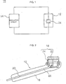
- Fig. 1 is a block diagram illustrating a first embodiment of the ultrasonic cosmetic treatment device of the present invention.
- Ultrasonic cosmetic treatment device 10 includes probe 12 that is held against an outer covering of a body, such as, but not limited to, for example, the skin on the face (or an other part of a body) to apply ultrasonic vibrations to the skin, and oscillation circuit 14 that supplies electrical power to probe 12.
- probe 12 is equipped with a grip part 16 that is grasped by the hand when the probe is used, and vibrating part 18, located at the end of the grip part 16, that comes into contact with the skin on the face.
- Grip part 16 is made from, for example, a synthetic resin and incorporates a channel 20 formed as an axially extending opening into which an electrical cord 25 is installed.
- vibrating part 18 incorporates skin contact member 22, made from, for example, a metallic material, attached to its forward facing surface, and an ultrasonic piezoelectric oscillator 24 having a piezoelectric element, attached to its rearward facing surface.
- Cord 25 is attached to the terminals of the ultrasonic oscillator 24, runs through channel 20 of grip part 16, and extends out of grip part 16 to connect to an externally located oscillation circuit 14.
- the construction of the probe 12 may be varied without departing from the spirit and/ir scope of the invention.
- the oscillation circuit may be housed in the probe 12 without departing from the scope and/or spirit of the invention.
- Oscillation circuit 14 having either a self exciter or separate exciter type oscillation circuit, drives ultrasonic oscillator 24, which is attached to the skin contact member 22, by supplying an oscillation output voltage at a specific oscillation frequency in an anti-resonance region (e.g., high impedance value) of ultrasonic oscillator 24.
- an anti-resonance region e.g., high impedance value
- oscillation circuit 14 may be housed within an externally located drive unit.
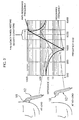
- vibrating part 18 has an impedance vs. frequency characteristic which, in regard to a specific frequency range, demonstrates a resonance for the lowest impedance value (e.g., the impedance of ultrasonic oscillator attached to skin contact member 22) and an anti-resonance for the highest impedance value.
- impedance vs. frequency characteristic which, in regard to a specific frequency range, demonstrates a resonance for the lowest impedance value (e.g., the impedance of ultrasonic oscillator attached to skin contact member 22) and an anti-resonance for the highest impedance value.
- This frequency vs. impedance characteristic exhibits differences that correspond to vibrating part 18 being in a load applied or non-load applied condition.
- a load applied condition results from part 18 being in contact with the skin
- a non-load applied condition results from part 18 not being in contact with the skin.
- vibrating part 18, as described in this embodiment exhibits a small impedance value in the frequency range of the resonant region below approximately 1,012 KHz when in a non-load applied condition, and a large impedance value in the frequency range of the anti-resonance region above approximately 1,012 KHz when in a load applied condition.
- alternative vibrating parts may be utilized that exhibit a resonant region and an anti-resource region at a frequency other than 1,012 KHz.
- the output voltage for the oscillating frequency can be supplied to ultrasonic oscillator 24 within the anti-resonance frequency region (shown in Fig. 3) for vibrating part 18 (ultrasonic oscillator 24 being attached to the skin contact member 22), thus eliminating the need for a monitoring circuit to detect whether the vibrating part 18 is in (or out of) contact with the skin, and further eliminating the need for an oscillation control circuit to control the output level of the oscillation circuit in response to the monitored results. Moreover, energy demands can be reduced due to the decrease in power consumption during the non-load applied condition.
- the frequency range labeled "Frequency Range Meeting Desired Conditions" is the range in which heat emission from the non-load applied vibrating part 18 can be controlled without a decrease in the efficiency of the oscillation circuit. It is also possible to set the oscillation circuit oscillation frequency beyond the upper limit of the oscillation frequency range.
- Fig. 4 is a block diagram describing a second embodiment of the ultrasonic cosmetic treatment device invention.
- oscillation circuit 26 of ultrasonic cosmetic treatment device 10A is structured as a separate exciter oscillation circuit.
- probe 12 has been previously described in the first embodiment and is essentially the same for this second embodiment, illustrations and explanations of the components comprising probe 12 will be omitted, but the same element numbers will be applied in the description of this second embodiment. The following description will deal with only those parts of the second embodiment of the invention that substantially differ from the first embodiment.
- the second embodiment ultrasonic cosmetic treatment device 10A includes probe 12, to which ultrasonic oscillator 24 is installed (as explained in the first embodiment) and separate exciter oscillation circuit 26 that drives ultrasonic oscillator 24.
- Separate exciter oscillation circuit 26 includes an oscillator 30 whose oscillating frequency is controlled by the phase locked loop (PLL) circuit 28, and an amplifier (amplifier circuit) 32 which is used to amplify the oscillating output of oscillator 30.
- PLL phase locked loop
- Phase locked loop circuit 28 includes components that make use of publicly known technology, such as, but not limited to, for example, a programmable frequency divider, a phase comparator, voltage controlled oscillator, and low range filter.
- the circuit can be structured, for example, so that the oscillation frequency is adjusted by applying the output voltage from a programmable frequency divider (not shown) to a variable capacity diode (not shown) associated with oscillator 30.
- a circuit is employed wherein oscillator 30 oscillates at a predetermined constant frequency (the frequency encompassing the anti-resonance range shown in Fig. 3) resulting from a constant voltage applied to the variable capacity diode.
- the oscillation output is then amplified by amplifier 32 and supplied to the ultrasonic oscillator 24, thus providing for a more stabilized method of driving the ultrasonic oscillator 24.
- oscillation circuit 26 is a separate exciter oscillation circuit structured so as to oscillate at a constant frequency in relation to the larger impedance value of vibrating part 18 resulting from part 18 being in a non-load applied condition, as compared to the small impedance value when the parts 18 is in the loaded condition.
- This second embodiment thus offers the same operational effect as the first embodiment, and because of the stable oscillation frequency provided by oscillation circuit 26, a stable ultrasonic vibration can be applied to the skin when vibrating part 18 is in the load applied condition. As a result, the thermal emission from the vibrating part 18 can be effectively controlled when the vibrating part 18 is in the non-load applied condition (e.g., vibrating part 18 is separated from the skin).
- this second embodiment provides for a highly stable oscillating frequency emanating from oscillation circuit 26 as a result of the inclusion of the phase locked loop circuit 28, stabilizing circuits of other design may also be applied to provide the stabilizing effect.
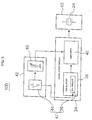
- Fig. 5 is a block diagram describing a third embodiment of the ultrasonic cosmetic treatment device invention, in which an oscillation circuit 34 of ultrasonic cosmetic treatment device 10B is structured as a separate exciter oscillation circuit as described in the second embodiment.
- an oscillation circuit 34 of ultrasonic cosmetic treatment device 10B is structured as a separate exciter oscillation circuit as described in the second embodiment.
- ultrasonic cosmetic treatment device 10B includes probe 12 which is equipped with ultrasonic oscillator 24 as previously described in the first embodiment, and separate exciter oscillation circuit 34 which is used to drive ultrasonic oscillator 24.
- Separate exciter oscillating circuit 34 includes an oscillation circuit 38 whose oscillating frequency is controlled by an oscillating frequency generated by phase locked loop circuit 36, and amplifier (amplification circuit) 40 that amplifies the oscillating output of oscillator 38.
- ultrasonic cosmetic treatment device 10B as described in this third embodiment, incorporates a VCC 42 that operates as an output voltage conversion part capable of switching the acoustic output, which is the mechanical vibrating output generated by ultrasonic oscillator 24, between a high state and a low level state.
- Phase lock loop circuit 36 is structured identically to that described in the second embodiment and can operate, for example, in a manner in which the voltage output from the programmable frequency divider is applied to the variable capacity diode installed in oscillating part 38 to change the oscillating frequency of oscillator 38.
- VCC 42 is structured so that the drive voltage supplied to amplifier 40 from a drive power source 46 can be changed to a HIGH or LOW level as a result of the switching operation of a changeover switch 44. That is, the drive power source 46 functions to switch the output voltage (e.g., the drive voltage applied to amplifier 40) between a HIGH and LOW level based on the input from the changeover switch 44.
- the drive power source 46 is configured as a constant DC voltage source that can change its output voltage. The output amplitude of amplifier 40 increases when supplied with a high level drive voltage, and decreases when supplied with a low level drive voltage.
- the acoustical output of ultrasonic oscillator 24 increases as a result of the increase in supplied power when there is a large amplitude output from amplifier 40, and decreases as a result of the decrease in supplied power when there is a small amplitude output from amplifier 40.
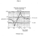
- Fig. 6 shows a state in which the resonance and anti-resonance ranges have shifted to a lower frequency than that shown in Fig. 3.
- the change in output voltage from the programmable frequency divider located in the phase locked loop circuit 36 can induce a change in the setting of the variable capacity diode in oscillator 38, thus causing a shift of the oscillation frequency to the anti-resonance region as a result of the decreased drive voltage.
- a changeover signal from the operation of the changeover switch 44 is supplied to the phase locked loop circuit 36, thus causing a corresponding change in the voltage output of, for example, a programmable frequency divider.
- the changeover switch 44 and phase locked loop circuit 36 are incorporated into the FCC 47 to change the oscillating frequency of the oscillation circuit 34.
- Fig. 7 shows the operating waveforms for each component of the ultrasonic cosmetic treatment device 10B as described in the third embodiment.
- the changeover switch 44 assumes a high level state (shown as "strong" in Fig. 8), for example, when a HIGH signal is output from the changeover switch 44, an increased drive voltage is output from the drive power source 46 and supplied to amplifier 40.
- oscillator 38 operates at a frequency within the anti-resonance region shown in Fig. 3 (a frequency higher than that of the anti-resonance frequency point region shown in Fig. 6).
- Amplifier 40 sets the output voltage for that frequency and supplies it to the ultrasonic oscillator 24, thus forming a mechanism through which a larger amplitude ultrasonic vibration is generated when vibrating part 18 is held in contact with the skin.
- changeover switch 44 assumes a low level state (shown as "weak” in Fig. 8), for example, when a LOW signal is output from changeover switch 44, a decreased drive voltage is supplied to amplifier 40 from the drive power source 46.
- oscillating part 38 operates at a frequency within the anti-resonance region shown in Fig. 6 (a frequency lower than that of the anti-resonance frequency point region shown in Fig. 3).
- Amplifier 40 set to a lower level of amplitude, then amplifies the output voltage and supplies it to ultrasonic oscillator 24, thus forming a mechanism through which an ultrasonic vibration of a lesser amplitude is generated when vibrating part 18 is not in contact with the skin.
- the third embodiment of the invention incorporates the oscillation circuit 34 structured as a separate exciter oscillation circuit, the VCC 42 that converts the voltage level output from oscillation circuit 34 supplied to ultrasonic oscillator 24, and the FCC 47 that converts the oscillation frequency of the oscillation circuit 34 based on the voltage level of the frequency, for the large impedance value of oscillating part 18 when in a non-load applied condition as compared to a small impedance value for a load applied condition.
- These structures and mechanisms enable the third embodiment of the invention to provide the same operational effects as the first embodiment, and makes it possible to change the level of the ultrasonic vibration when the device is put in contact with the skin, thus allowing the user to operate the ultrasonic cosmetic treatment device with a greater degree of comfort.
- the third embodiment employs the FCC 47 structured to include the phase locked loop circuit 38 and the changeover switch 44 as one example of a means for changing the oscillation frequency of oscillation circuit 34
- other types of circuit structures may be employed to change the oscillation frequency of oscillation circuit 34 without departing from the scope and/or spirit of the present invention.
- the frequency region labeled "Frequency Range Meeting Desired Conditions,” as similarly shown in Fig. 3 is the frequency range in which a heat emission can be controlled without any falloff in the operating efficiency of the oscillation circuit when vibrating part 18 is in a non-load applied condition.
- This structure also makes it possible to set the oscillation frequency of the oscillating circuit to a level exceeding the upper limit of the frequency range.
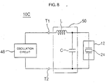
- Fig. 8 is a block diagram describing a fourth embodiment of the ultrasonic cosmetic device invention.
- the fourth embodiment shown as ultrasonic cosmetic treatment device 10C, employs an oscillation circuit structured as a self exciter type of oscillation circuit.
- an oscillation circuit structured as a self exciter type of oscillation circuit.
- probe 12 As the structure of probe 12 has been previously described in the first embodiment and is essentially the same for this fourth embodiment, detailed illustrations and explanations of probe 12 components will be omitted but the same component numbers will be applied. The following descriptions will deal with only those parts of the fourth embodiment that substantially differ from the first embodiment.
- the fourth embodiment of the invention shown in Fig. 8 as ultrasonic cosmetic treatment device 10C, comprises probe 12 that incorporates the ultrasonic oscillator 24, as described in the first embodiment, a self exciter oscillation circuit 48 that drives the ultrasonic oscillator 24, and oscillation frequency rectifier circuit 50 that incorporates an LC circuit connected to the ultrasonic oscillator 24 and the self exciter oscillation circuit 48.
- the self exciter oscillation circuit 48 is structured as a Colpitts oscillating circuit to which a load (i.e., a synthetic impedance for vibrating part 18 and oscillation frequency rectifier circuit 50) is applied between output terminals T1 and T2, in which the circuit oscillates when the phase angle of the load becomes zero degrees.
- a load i.e., a synthetic impedance for vibrating part 18 and oscillation frequency rectifier circuit 50
- oscillation circuit 48 will oscillate at a frequency only when the impedance of the load applied between output terminals T1 and T2 becomes a resistive component (that is, when the imaginary number part of an impedance for a complex number becomes zero).
- a resistive component that is, when the imaginary number part of an impedance for a complex number becomes zero.
- other types of oscillators may be used.
- Oscillation frequency rectifier circuit 50 may, for example, be located within probe 12, and include an inductor L connected in series to the ultrasonic oscillator 24, and a capacitor C connected in parallel to the ultrasonic oscillator 24, thus providing a mechanism through which a frequency for a zero degree phase load can be shifted into an anti-resonance frequency region output by the ultrasonic oscillator 24.
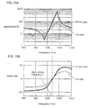
- the circuit operation will be described for a case in which the ultrasonic cosmetic treatment device 10C is not equipped with the oscillation frequency rectifier circuit 50.
- the load frequency vs. phase characteristics in Fig. 9B relating to the impedance of the vibrating part 18 only
- the frequency for a zero degree phase load is the same for both the load applied condition and the non-load applied condition.
- the frequency resides within both the frequency resonance and anti-resonance regions in regard to the frequency vs. impedance characteristics of vibrating part 18 (see Fig. 9A).
- the frequency output by oscillation circuit 48 moves to the low side when the load phase is a positive (+) value, and as a result of the frequency moving to the high side when the load phase is a negative (-) value, an oscillation frequency is output in relation to the resonance point of the vibrating part 18.
- the oscillation circuit 48 operates at this frequency, the power supplied to the ultrasonic oscillator 24 is greater than the rated power, because the impedance value becomes smaller for a non-load applied condition of the vibrating part 18 as compared to a load applied condition, thus causing the temperature of the vibrating part 18 to rise as a result of an increased heat emission.
- oscillation circuit 48 drives ultrasonic oscillator 24 at a power level less than the rated power, thus effectively controlling a thermal emission from the vibrating part 18.
- the invention described in the fourth embodiment as including a Colpitts type self exciter oscillation circuit, is able to provide the same operational effect of the first embodiment invention, due to the ability of the oscillation frequency rectifier circuit 50 to adjust the oscillation circuit frequency in relation to a large impedance value of the vibrating part 18 as compared to a small impedance value.
- this embodiment provides the benefit of a simpler oscillation circuit structure as compared to a separate exciter type oscillation circuit.
- the oscillation frequency rectifier circuit 50 is structured to include the ultrasonic oscillator 24 to which the inductor L is connected in series, and the capacitor C is connected in parallel, this embodiment is not limited to this type of circuit structure alone. Moreover, while this embodiment discloses that the oscillation frequency rectifier circuit 50 is connected between the ultrasonic oscillator 24 and the oscillation circuit 48, the invention is not limited to this type of connection alone.
- the oscillation frequency rectifier circuit 50 may be located within the oscillation circuit 48 (in other words, not directly connected to terminals T1 and T2, but a part of circuit 48).
- oscillation frequency rectifier circuit 50 can be installed within the driver part of the invention which also houses the oscillation circuit 48 to which the probe cord 25 is connected.
- a structure in which the oscillation frequency rectifier circuit 50 is located between the oscillation circuit 48 and ultrasonic oscillator 24 may be utilized.
- the oscillation frequency rectifier circuit 50 may be located within, for example, the probe 12, or connected to the central part of the cord 25 between probe 12 and the driving part.
- the structure of the self exciter oscillation circuit 48 is not limited to the Colpitts type, but may be structured as, for example, a Hartley or other type of oscillating circuit.
- the first embodiment describes an invention incorporating a probe comprised of a skin contact member, a vibrating part, and an ultrasonic oscillator attached to the rear of the vibrating part, a load applied condition being applied to the vibrating part when the vibrating part is in contact with the skin.
- the first embodiment further comprises an oscillation circuit that, at the time a non-load applied condition exists (as a result of the vibrating part not being in contact with the skin), drives an ultrasonic oscillator at an oscillating frequency relating to the larger impedance value of the non-load applied condition as compared to the smaller impedance value of a loaded condition, thus providing for a simple circuit structure able to effectively control a thermal emission from the vibrating part when not in contact with the skin.
- the invention described by the second embodiment incorporates an oscillation circuit structured as a separated exciter type oscillation circuit that oscillates at a constant frequency in relation to the larger impedance value of the vibrating part's non-load applied condition (as opposed to the smaller impedance value of a load applied condition), thus providing a mechanism through which stable ultrasonic oscillation is attained during a load applied condition when the vibrating part is in contact with the skin, and through which the supply power relating to the vibrating part's larger impedance value during a non-load applied condition (as opposed to a small impedance value for a load applied condition) is supplied at a level lower than the rated power, thus providing a method for effectively controlling a heat emission from the vibrating part.
- the invention described by the third embodiment incorporates an oscillation circuit structured as a separated exciter type oscillation circuit, a VCC that operates to change the voltage level applied to the ultrasonic oscillator from the oscillation circuit, and FCC that operates to change the oscillation frequency of the oscillation circuit according to a voltage that relates to the vibrating part's larger impedance value during a non-load applied condition (as opposed to a smaller impedance for a load applied condition), thus providing a mechanism through which the acoustic output level of the ultrasonic oscillator can be changed, and through which a heat emission from the vibrating part can, regardless of the acoustic output level, be effectively controlled during a non-loaded condition.
- an oscillation circuit structured as a separated exciter type oscillation circuit
- VCC that operates to change the voltage level applied to the ultrasonic oscillator from the oscillation circuit
- FCC that operates to change the oscillation frequency of the oscillation circuit according to a voltage that relates to the vibrating part's larger im
- the invention described by the fourth embodiment incorporates an oscillation circuit structured as a self exciter oscillation circuit, and includes an oscillation frequency rectifier circuit that rectifies the frequency output by the oscillation circuit in relation to the vibrating part's larger impedance value for a non-load applied condition (as compared to a smaller impedance value for a load applied condition), thus providing for a simple circuit that effectively reduces thermal emission from the vibrating part when the vibrating part is not in contact with the skin.
Landscapes
- Health & Medical Sciences (AREA)
- Epidemiology (AREA)
- Pain & Pain Management (AREA)
- Physical Education & Sports Medicine (AREA)
- Rehabilitation Therapy (AREA)
- Life Sciences & Earth Sciences (AREA)
- Animal Behavior & Ethology (AREA)
- General Health & Medical Sciences (AREA)
- Public Health (AREA)
- Veterinary Medicine (AREA)
- Percussion Or Vibration Massage (AREA)
- Apparatuses For Generation Of Mechanical Vibrations (AREA)
Abstract
Description
Claims (6)
- An ultrasonic cosmetic treatment device, comprising:a probe (12) having a vibrating part (18) formed by a contact member (22) and an ultrasonic oscillator (24) attached to a rear side of said contact member (22);an oscillation circuit (14; 34; 48) that drives said ultrasonic oscillator (24) at a frequency corresponding to a first impedance value of said vibrating part (18) when in a non-load applied condition resulting from said vibrating part (18) not being in contact with a predetermined surface, said first impedance value being larger than a second impedance value of said vibrating part (18) in a load applied condition resulting from said vibrating part (18) being in contact with said predetermined surface; characterized in that said oscillation circuit (14,34,48) further comprisesa voltage changing circuit (42) to change a voltage level applied to said ultrasonic oscillator (24) from said oscillation circuit (34; 48), and a frequency changing circuit (47) to change an oscillation frequency of said oscillation circuit (34; 48) according to said voltage level in relation to an impedance value of said vibrating part (18) when said vibrating part (18) is in said non-load applied condition.
- The ultrasonic cosmetic treatment device of claim 1, wherein said oscillation circuit comprises a separated exciter type oscillation circuit (34; 48).
- The ultrasonic cosmetic treatment device of claim 2, wherein said separated exciter type oscillation circuit (34; 48) oscillates at a constant frequency corresponding to said first impedance value of said vibrating part (18) when in said non-load applied condition.
- The ultrasonic cosmetic treatment device of any of claims 1 to 3, wherein said oscillation circuit comprises a self exciting oscillation circuit (48), said ultrasonic cosmetic treatment device further comprising an oscillation frequency rectifier circuit (50) that adjusts an oscillation frequency of said oscillation circuit (48) in relation to said first impedance value of said vibrating part (18) when said vibrating part (18) is in said non-load applied condition.
- The ultrasonic cosmetic treatment device of any of claims 1 to 4, wherein said predetermined surface comprises an outer covering of a body.
- The ultrasonic cosmetic treatment device of any of claims 1 to 5, further comprising an oscillation frequency rectifier circuit (50) that is interposed between said oscillation circuit (34; 48) and said ultrasonic oscillator (24).
Applications Claiming Priority (2)
| Application Number | Priority Date | Filing Date | Title |
|---|---|---|---|
| JP2001049205A JP2002248153A (en) | 2001-02-23 | 2001-02-23 | Ultrasonic cosmetic device |
| JP2001049205 | 2001-02-23 |
Publications (2)
| Publication Number | Publication Date |
|---|---|
| EP1234566A1 EP1234566A1 (en) | 2002-08-28 |
| EP1234566B1 true EP1234566B1 (en) | 2005-08-31 |
Family
ID=18910343
Family Applications (1)
| Application Number | Title | Priority Date | Filing Date |
|---|---|---|---|
| EP02003853A Expired - Lifetime EP1234566B1 (en) | 2001-02-23 | 2002-02-20 | Ultrasonic cosmetic treatment device |
Country Status (5)
| Country | Link |
|---|---|
| US (1) | US20020120218A1 (en) |
| EP (1) | EP1234566B1 (en) |
| JP (1) | JP2002248153A (en) |
| AT (1) | ATE303117T1 (en) |
| DE (1) | DE60205788T2 (en) |
Cited By (30)
| Publication number | Priority date | Publication date | Assignee | Title |
|---|---|---|---|---|
| US7758524B2 (en) | 2004-10-06 | 2010-07-20 | Guided Therapy Systems, L.L.C. | Method and system for ultra-high frequency ultrasound treatment |
| US7824348B2 (en) | 2004-09-16 | 2010-11-02 | Guided Therapy Systems, L.L.C. | System and method for variable depth ultrasound treatment |
| US8066641B2 (en) | 2004-10-06 | 2011-11-29 | Guided Therapy Systems, L.L.C. | Method and system for treating photoaged tissue |
| US8133180B2 (en) | 2004-10-06 | 2012-03-13 | Guided Therapy Systems, L.L.C. | Method and system for treating cellulite |
| US8166332B2 (en) | 2005-04-25 | 2012-04-24 | Ardent Sound, Inc. | Treatment system for enhancing safety of computer peripheral for use with medical devices by isolating host AC power |
| US8235909B2 (en) | 2004-05-12 | 2012-08-07 | Guided Therapy Systems, L.L.C. | Method and system for controlled scanning, imaging and/or therapy |
| US8282554B2 (en) | 2004-10-06 | 2012-10-09 | Guided Therapy Systems, Llc | Methods for treatment of sweat glands |
| US8409097B2 (en) | 2000-12-28 | 2013-04-02 | Ardent Sound, Inc | Visual imaging system for ultrasonic probe |
| US8444562B2 (en) | 2004-10-06 | 2013-05-21 | Guided Therapy Systems, Llc | System and method for treating muscle, tendon, ligament and cartilage tissue |
| US8480585B2 (en) | 1997-10-14 | 2013-07-09 | Guided Therapy Systems, Llc | Imaging, therapy and temperature monitoring ultrasonic system and method |
| US8535228B2 (en) | 2004-10-06 | 2013-09-17 | Guided Therapy Systems, Llc | Method and system for noninvasive face lifts and deep tissue tightening |
| US8663112B2 (en) | 2004-10-06 | 2014-03-04 | Guided Therapy Systems, Llc | Methods and systems for fat reduction and/or cellulite treatment |
| US8690778B2 (en) | 2004-10-06 | 2014-04-08 | Guided Therapy Systems, Llc | Energy-based tissue tightening |
| US8715186B2 (en) | 2009-11-24 | 2014-05-06 | Guided Therapy Systems, Llc | Methods and systems for generating thermal bubbles for improved ultrasound imaging and therapy |
| US8764687B2 (en) | 2007-05-07 | 2014-07-01 | Guided Therapy Systems, Llc | Methods and systems for coupling and focusing acoustic energy using a coupler member |
| US8858471B2 (en) | 2011-07-10 | 2014-10-14 | Guided Therapy Systems, Llc | Methods and systems for ultrasound treatment |
| US8857438B2 (en) | 2010-11-08 | 2014-10-14 | Ulthera, Inc. | Devices and methods for acoustic shielding |
| US8915870B2 (en) | 2004-10-06 | 2014-12-23 | Guided Therapy Systems, Llc | Method and system for treating stretch marks |
| US9011336B2 (en) | 2004-09-16 | 2015-04-21 | Guided Therapy Systems, Llc | Method and system for combined energy therapy profile |
| US9011337B2 (en) | 2011-07-11 | 2015-04-21 | Guided Therapy Systems, Llc | Systems and methods for monitoring and controlling ultrasound power output and stability |
| US9114247B2 (en) | 2004-09-16 | 2015-08-25 | Guided Therapy Systems, Llc | Method and system for ultrasound treatment with a multi-directional transducer |
| US9149658B2 (en) | 2010-08-02 | 2015-10-06 | Guided Therapy Systems, Llc | Systems and methods for ultrasound treatment |
| US9216276B2 (en) | 2007-05-07 | 2015-12-22 | Guided Therapy Systems, Llc | Methods and systems for modulating medicants using acoustic energy |
| US9241683B2 (en) | 2006-10-04 | 2016-01-26 | Ardent Sound Inc. | Ultrasound system and method for imaging and/or measuring displacement of moving tissue and fluid |
| US9263663B2 (en) | 2012-04-13 | 2016-02-16 | Ardent Sound, Inc. | Method of making thick film transducer arrays |
| US9504446B2 (en) | 2010-08-02 | 2016-11-29 | Guided Therapy Systems, Llc | Systems and methods for coupling an ultrasound source to tissue |
| US9510802B2 (en) | 2012-09-21 | 2016-12-06 | Guided Therapy Systems, Llc | Reflective ultrasound technology for dermatological treatments |
| US9566454B2 (en) | 2006-09-18 | 2017-02-14 | Guided Therapy Systems, Llc | Method and sysem for non-ablative acne treatment and prevention |
| US11590370B2 (en) | 2004-09-24 | 2023-02-28 | Guided Therapy Systems, Llc | Rejuvenating skin by heating tissue for cosmetic treatment of the face and body |
| US11969609B2 (en) | 2022-12-05 | 2024-04-30 | Ulthera, Inc. | Devices and methods for multi-focus ultrasound therapy |
Families Citing this family (22)
| Publication number | Priority date | Publication date | Assignee | Title |
|---|---|---|---|---|
| KR100507453B1 (en) * | 2003-06-17 | 2005-08-08 | (주)로츠 | Method and apparatus for controlling the power of a skin care device, and handable skin care device using the same |
| US11883688B2 (en) | 2004-10-06 | 2024-01-30 | Guided Therapy Systems, Llc | Energy based fat reduction |
| US9827449B2 (en) | 2004-10-06 | 2017-11-28 | Guided Therapy Systems, L.L.C. | Systems for treating skin laxity |
| US9694212B2 (en) | 2004-10-06 | 2017-07-04 | Guided Therapy Systems, Llc | Method and system for ultrasound treatment of skin |
| US11235179B2 (en) | 2004-10-06 | 2022-02-01 | Guided Therapy Systems, Llc | Energy based skin gland treatment |
| US11207548B2 (en) | 2004-10-07 | 2021-12-28 | Guided Therapy Systems, L.L.C. | Ultrasound probe for treating skin laxity |
| US11724133B2 (en) | 2004-10-07 | 2023-08-15 | Guided Therapy Systems, Llc | Ultrasound probe for treatment of skin |
| JP4572789B2 (en) * | 2005-09-27 | 2010-11-04 | パナソニック電工株式会社 | Ultrasonic generator and ultrasonic beauty device |
| JP4665716B2 (en) * | 2005-10-26 | 2011-04-06 | パナソニック電工株式会社 | Ultrasonic vibrator for hair styling |
| US20070239101A1 (en) * | 2006-02-21 | 2007-10-11 | David Kellogg | Method for applying serum to a person's skin |
| US20070198031A1 (en) * | 2006-02-21 | 2007-08-23 | David Kellogg | Method for performing dermabrasion |
| JP5027496B2 (en) * | 2006-12-22 | 2012-09-19 | パナソニック株式会社 | Ultrasonic facial device |
| US20150174388A1 (en) | 2007-05-07 | 2015-06-25 | Guided Therapy Systems, Llc | Methods and Systems for Ultrasound Assisted Delivery of a Medicant to Tissue |
| US7759766B2 (en) * | 2007-08-22 | 2010-07-20 | International Business Machines Corporation | Electrical fuse having a thin fuselink |
| CN104545998B (en) | 2008-06-06 | 2020-07-14 | 奥赛拉公司 | System and method for cosmetic treatment and imaging |
| CN204017181U (en) | 2013-03-08 | 2014-12-17 | 奥赛拉公司 | Aesthstic imaging and processing system, multifocal processing system and perform the system of aesthetic procedure |
| US10561862B2 (en) | 2013-03-15 | 2020-02-18 | Guided Therapy Systems, Llc | Ultrasound treatment device and methods of use |
| SG11201608691YA (en) | 2014-04-18 | 2016-11-29 | Ulthera Inc | Band transducer ultrasound therapy |
| ES2939604T3 (en) | 2016-01-18 | 2023-04-25 | Ulthera Inc | Compact ultrasonic device having an annular ultrasonic array peripherally electrically connected to a flexible printed circuit board |
| US11241218B2 (en) | 2016-08-16 | 2022-02-08 | Ulthera, Inc. | Systems and methods for cosmetic ultrasound treatment of skin |
| JP7228216B2 (en) * | 2017-05-31 | 2023-02-24 | 株式会社Tryangle & Co. | Solid-state oscillator circuit, ultrasonic beauty device |
| US11944849B2 (en) | 2018-02-20 | 2024-04-02 | Ulthera, Inc. | Systems and methods for combined cosmetic treatment of cellulite with ultrasound |
Family Cites Families (16)
| Publication number | Priority date | Publication date | Assignee | Title |
|---|---|---|---|---|
| US3432691A (en) * | 1966-09-15 | 1969-03-11 | Branson Instr | Oscillatory circuit for electro-acoustic converter |
| JPS5881470A (en) * | 1981-11-10 | 1983-05-16 | 東北金属工業株式会社 | Oscillator circuit for ultrasonic processing machine |
| DE3317045A1 (en) * | 1983-05-10 | 1984-11-15 | Martin Walter Ultraschalltechnik GmbH, 7516 Karlsbad | METHOD AND ARRANGEMENT FOR THE CONSTANT POWER DELIVERY OF ULTRASONIC CLEANING SYSTEMS |
| US4823042A (en) * | 1986-07-18 | 1989-04-18 | Rich-Mar Corporation | Sonic transducer and method for making the same |
| US4966131A (en) * | 1988-02-09 | 1990-10-30 | Mettler Electronics Corp. | Ultrasound power generating system with sampled-data frequency control |
| US5086788A (en) * | 1988-06-13 | 1992-02-11 | Castel John C | Hand-held physiological stimulation applicator |
| US5151085A (en) * | 1989-04-28 | 1992-09-29 | Olympus Optical Co., Ltd. | Apparatus for generating ultrasonic oscillation |
| US5184605A (en) * | 1991-01-31 | 1993-02-09 | Excel Tech Ltd. | Therapeutic ultrasound generator with radiation dose control |
| KR950700131A (en) * | 1992-02-07 | 1995-01-16 | 알렌 제이. 스피겔 | Ultrasonic Piezoelectric Crystal Transducer Control Systems for Monitoring Electrical and Electronic Control Loops and Their Combination Systems (ULTRASONIC SURGICAL APPARATUS) |
| JP3549922B2 (en) * | 1994-06-14 | 2004-08-04 | オージー技研株式会社 | Ultrasound therapy device with protection circuit |
| US5618275A (en) * | 1995-10-27 | 1997-04-08 | Sonex International Corporation | Ultrasonic method and apparatus for cosmetic and dermatological applications |
| JP2942886B2 (en) * | 1996-07-26 | 1999-08-30 | 進 永井 | Ultrasound therapy apparatus and method of driving transducer |
| TW370458B (en) * | 1997-08-11 | 1999-09-21 | Matsushita Electric Works Ltd | Ultrasonic facial apparatus |
| JPH11114000A (en) | 1997-08-11 | 1999-04-27 | Matsushita Electric Works Ltd | Ultrasonic cosmetic device |
| US6908472B2 (en) * | 2000-10-20 | 2005-06-21 | Ethicon Endo-Surgery, Inc. | Apparatus and method for altering generator functions in an ultrasonic surgical system |
| US6626926B2 (en) * | 2000-10-20 | 2003-09-30 | Ethicon Endo-Surgery, Inc. | Method for driving an ultrasonic system to improve acquisition of blade resonance frequency at startup |
-
2001
- 2001-02-23 JP JP2001049205A patent/JP2002248153A/en active Pending
-
2002
- 2002-02-20 US US10/077,809 patent/US20020120218A1/en not_active Abandoned
- 2002-02-20 DE DE60205788T patent/DE60205788T2/en not_active Expired - Lifetime
- 2002-02-20 AT AT02003853T patent/ATE303117T1/en not_active IP Right Cessation
- 2002-02-20 EP EP02003853A patent/EP1234566B1/en not_active Expired - Lifetime
Cited By (61)
| Publication number | Priority date | Publication date | Assignee | Title |
|---|---|---|---|---|
| US8480585B2 (en) | 1997-10-14 | 2013-07-09 | Guided Therapy Systems, Llc | Imaging, therapy and temperature monitoring ultrasonic system and method |
| US9272162B2 (en) | 1997-10-14 | 2016-03-01 | Guided Therapy Systems, Llc | Imaging, therapy, and temperature monitoring ultrasonic method |
| US8409097B2 (en) | 2000-12-28 | 2013-04-02 | Ardent Sound, Inc | Visual imaging system for ultrasonic probe |
| US8235909B2 (en) | 2004-05-12 | 2012-08-07 | Guided Therapy Systems, L.L.C. | Method and system for controlled scanning, imaging and/or therapy |
| US7824348B2 (en) | 2004-09-16 | 2010-11-02 | Guided Therapy Systems, L.L.C. | System and method for variable depth ultrasound treatment |
| US8708935B2 (en) | 2004-09-16 | 2014-04-29 | Guided Therapy Systems, Llc | System and method for variable depth ultrasound treatment |
| US9114247B2 (en) | 2004-09-16 | 2015-08-25 | Guided Therapy Systems, Llc | Method and system for ultrasound treatment with a multi-directional transducer |
| US9011336B2 (en) | 2004-09-16 | 2015-04-21 | Guided Therapy Systems, Llc | Method and system for combined energy therapy profile |
| US11590370B2 (en) | 2004-09-24 | 2023-02-28 | Guided Therapy Systems, Llc | Rejuvenating skin by heating tissue for cosmetic treatment of the face and body |
| US9095697B2 (en) | 2004-09-24 | 2015-08-04 | Guided Therapy Systems, Llc | Methods for preheating tissue for cosmetic treatment of the face and body |
| US8915870B2 (en) | 2004-10-06 | 2014-12-23 | Guided Therapy Systems, Llc | Method and system for treating stretch marks |
| US9440096B2 (en) | 2004-10-06 | 2016-09-13 | Guided Therapy Systems, Llc | Method and system for treating stretch marks |
| US8460193B2 (en) | 2004-10-06 | 2013-06-11 | Guided Therapy Systems Llc | System and method for ultra-high frequency ultrasound treatment |
| US8506486B2 (en) | 2004-10-06 | 2013-08-13 | Guided Therapy Systems, Llc | Ultrasound treatment of sub-dermal tissue for cosmetic effects |
| US8523775B2 (en) | 2004-10-06 | 2013-09-03 | Guided Therapy Systems, Llc | Energy based hyperhidrosis treatment |
| US8535228B2 (en) | 2004-10-06 | 2013-09-17 | Guided Therapy Systems, Llc | Method and system for noninvasive face lifts and deep tissue tightening |
| US8636665B2 (en) | 2004-10-06 | 2014-01-28 | Guided Therapy Systems, Llc | Method and system for ultrasound treatment of fat |
| US8641622B2 (en) | 2004-10-06 | 2014-02-04 | Guided Therapy Systems, Llc | Method and system for treating photoaged tissue |
| US8663112B2 (en) | 2004-10-06 | 2014-03-04 | Guided Therapy Systems, Llc | Methods and systems for fat reduction and/or cellulite treatment |
| US8672848B2 (en) | 2004-10-06 | 2014-03-18 | Guided Therapy Systems, Llc | Method and system for treating cellulite |
| US8690778B2 (en) | 2004-10-06 | 2014-04-08 | Guided Therapy Systems, Llc | Energy-based tissue tightening |
| US8690779B2 (en) | 2004-10-06 | 2014-04-08 | Guided Therapy Systems, Llc | Noninvasive aesthetic treatment for tightening tissue |
| US8690780B2 (en) | 2004-10-06 | 2014-04-08 | Guided Therapy Systems, Llc | Noninvasive tissue tightening for cosmetic effects |
| US8444562B2 (en) | 2004-10-06 | 2013-05-21 | Guided Therapy Systems, Llc | System and method for treating muscle, tendon, ligament and cartilage tissue |
| US7758524B2 (en) | 2004-10-06 | 2010-07-20 | Guided Therapy Systems, L.L.C. | Method and system for ultra-high frequency ultrasound treatment |
| US9533175B2 (en) | 2004-10-06 | 2017-01-03 | Guided Therapy Systems, Llc | Energy based fat reduction |
| US9522290B2 (en) | 2004-10-06 | 2016-12-20 | Guided Therapy Systems, Llc | System and method for fat and cellulite reduction |
| US8066641B2 (en) | 2004-10-06 | 2011-11-29 | Guided Therapy Systems, L.L.C. | Method and system for treating photoaged tissue |
| US9427600B2 (en) | 2004-10-06 | 2016-08-30 | Guided Therapy Systems, L.L.C. | Systems for treating skin laxity |
| US8915853B2 (en) | 2004-10-06 | 2014-12-23 | Guided Therapy Systems, Llc | Methods for face and neck lifts |
| US8366622B2 (en) | 2004-10-06 | 2013-02-05 | Guided Therapy Systems, Llc | Treatment of sub-dermal regions for cosmetic effects |
| US8915854B2 (en) | 2004-10-06 | 2014-12-23 | Guided Therapy Systems, Llc | Method for fat and cellulite reduction |
| US8920324B2 (en) | 2004-10-06 | 2014-12-30 | Guided Therapy Systems, Llc | Energy based fat reduction |
| US8932224B2 (en) | 2004-10-06 | 2015-01-13 | Guided Therapy Systems, Llc | Energy based hyperhidrosis treatment |
| US8333700B1 (en) | 2004-10-06 | 2012-12-18 | Guided Therapy Systems, L.L.C. | Methods for treatment of hyperhidrosis |
| US9427601B2 (en) | 2004-10-06 | 2016-08-30 | Guided Therapy Systems, Llc | Methods for face and neck lifts |
| US9421029B2 (en) | 2004-10-06 | 2016-08-23 | Guided Therapy Systems, Llc | Energy based hyperhidrosis treatment |
| US9039619B2 (en) | 2004-10-06 | 2015-05-26 | Guided Therapy Systems, L.L.C. | Methods for treating skin laxity |
| US8282554B2 (en) | 2004-10-06 | 2012-10-09 | Guided Therapy Systems, Llc | Methods for treatment of sweat glands |
| US8133180B2 (en) | 2004-10-06 | 2012-03-13 | Guided Therapy Systems, L.L.C. | Method and system for treating cellulite |
| US9320537B2 (en) | 2004-10-06 | 2016-04-26 | Guided Therapy Systems, Llc | Methods for noninvasive skin tightening |
| US9283409B2 (en) | 2004-10-06 | 2016-03-15 | Guided Therapy Systems, Llc | Energy based fat reduction |
| US9283410B2 (en) | 2004-10-06 | 2016-03-15 | Guided Therapy Systems, L.L.C. | System and method for fat and cellulite reduction |
| US8166332B2 (en) | 2005-04-25 | 2012-04-24 | Ardent Sound, Inc. | Treatment system for enhancing safety of computer peripheral for use with medical devices by isolating host AC power |
| US8868958B2 (en) | 2005-04-25 | 2014-10-21 | Ardent Sound, Inc | Method and system for enhancing computer peripheral safety |
| US9566454B2 (en) | 2006-09-18 | 2017-02-14 | Guided Therapy Systems, Llc | Method and sysem for non-ablative acne treatment and prevention |
| US9241683B2 (en) | 2006-10-04 | 2016-01-26 | Ardent Sound Inc. | Ultrasound system and method for imaging and/or measuring displacement of moving tissue and fluid |
| US9216276B2 (en) | 2007-05-07 | 2015-12-22 | Guided Therapy Systems, Llc | Methods and systems for modulating medicants using acoustic energy |
| US8764687B2 (en) | 2007-05-07 | 2014-07-01 | Guided Therapy Systems, Llc | Methods and systems for coupling and focusing acoustic energy using a coupler member |
| US9345910B2 (en) | 2009-11-24 | 2016-05-24 | Guided Therapy Systems Llc | Methods and systems for generating thermal bubbles for improved ultrasound imaging and therapy |
| US9039617B2 (en) | 2009-11-24 | 2015-05-26 | Guided Therapy Systems, Llc | Methods and systems for generating thermal bubbles for improved ultrasound imaging and therapy |
| US8715186B2 (en) | 2009-11-24 | 2014-05-06 | Guided Therapy Systems, Llc | Methods and systems for generating thermal bubbles for improved ultrasound imaging and therapy |
| US9504446B2 (en) | 2010-08-02 | 2016-11-29 | Guided Therapy Systems, Llc | Systems and methods for coupling an ultrasound source to tissue |
| US9149658B2 (en) | 2010-08-02 | 2015-10-06 | Guided Therapy Systems, Llc | Systems and methods for ultrasound treatment |
| US8857438B2 (en) | 2010-11-08 | 2014-10-14 | Ulthera, Inc. | Devices and methods for acoustic shielding |
| US8858471B2 (en) | 2011-07-10 | 2014-10-14 | Guided Therapy Systems, Llc | Methods and systems for ultrasound treatment |
| US9452302B2 (en) | 2011-07-10 | 2016-09-27 | Guided Therapy Systems, Llc | Systems and methods for accelerating healing of implanted material and/or native tissue |
| US9011337B2 (en) | 2011-07-11 | 2015-04-21 | Guided Therapy Systems, Llc | Systems and methods for monitoring and controlling ultrasound power output and stability |
| US9263663B2 (en) | 2012-04-13 | 2016-02-16 | Ardent Sound, Inc. | Method of making thick film transducer arrays |
| US9510802B2 (en) | 2012-09-21 | 2016-12-06 | Guided Therapy Systems, Llc | Reflective ultrasound technology for dermatological treatments |
| US11969609B2 (en) | 2022-12-05 | 2024-04-30 | Ulthera, Inc. | Devices and methods for multi-focus ultrasound therapy |
Also Published As
| Publication number | Publication date |
|---|---|
| ATE303117T1 (en) | 2005-09-15 |
| US20020120218A1 (en) | 2002-08-29 |
| DE60205788T2 (en) | 2006-07-06 |
| EP1234566A1 (en) | 2002-08-28 |
| JP2002248153A (en) | 2002-09-03 |
| DE60205788D1 (en) | 2005-10-06 |
Similar Documents
| Publication | Publication Date | Title |
|---|---|---|
| EP1234566B1 (en) | Ultrasonic cosmetic treatment device | |
| US4445063A (en) | Energizing circuit for ultrasonic transducer | |
| US6997935B2 (en) | Resonant converter tuning for maintaining substantially constant phaco handpiece power under increased load | |
| EP1195460B1 (en) | Ultrasonic cleaning apparatus and ultrasonic cleaning method | |
| US5451161A (en) | Oscillating circuit for ultrasonic dental scaler | |
| US6176840B1 (en) | Ultrasonic cosmetic treatment device | |
| CN100518674C (en) | Pulsed ultrasonic device and method | |
| JPH11309171A (en) | Method and device for optimizing drive of piezoelectric actuator, particularly phacoemulsifier by detecting electromechanical characteristic | |
| CA2000581A1 (en) | Ultrasonic surgical operation device using bolted langevin transducer | |
| CN104602630B (en) | Ultrasound wave transfer unit | |
| JP2001258089A (en) | Ultrasound driver and ultrasound surgical device | |
| JP3209545B2 (en) | Ultrasonic drive | |
| JP2000334019A (en) | Ultrasonic beauty culture apparatus | |
| KR20040022550A (en) | Piezo-electric vibration unit using a ultrasonic | |
| JP3486469B2 (en) | Drive device for piezoelectric vibrator | |
| JP2002102578A (en) | Ultrasonic washing device | |
| JP2606496Y2 (en) | Ultrasound therapy equipment | |
| JPH0219147A (en) | Transmitter for inside/outside energy of organism | |
| KR200183691Y1 (en) | A ultrasound skin massage apparatus | |
| JP4419774B2 (en) | Ultrasonic beauty equipment | |
| US5389852A (en) | Ultrasonic signal converter | |
| JP2001095875A (en) | Ultrasonic equipment for fitness and beauty | |
| JP4850043B2 (en) | Vibration application equipment | |
| KR200312996Y1 (en) | Piezo-electric vibration unit using a ultrasonic | |
| JPH0379199A (en) | Transmitter/receiver |
Legal Events
| Date | Code | Title | Description |
|---|---|---|---|
| PUAI | Public reference made under article 153(3) epc to a published international application that has entered the european phase |
Free format text: ORIGINAL CODE: 0009012 |
|
| AK | Designated contracting states |
Kind code of ref document: A1 Designated state(s): AT BE CH CY DE DK ES FI FR GB GR IE IT LI LU MC NL PT SE TR |
|
| AX | Request for extension of the european patent |
Free format text: AL;LT;LV;MK;RO;SI |
|
| 17P | Request for examination filed |
Effective date: 20021025 |
|
| AKX | Designation fees paid |
Designated state(s): AT BE CH CY DE DK ES FI FR GB GR IE IT LI LU MC NL PT SE TR |
|
| 17Q | First examination report despatched |
Effective date: 20030910 |
|
| GRAP | Despatch of communication of intention to grant a patent |
Free format text: ORIGINAL CODE: EPIDOSNIGR1 |
|
| GRAS | Grant fee paid |
Free format text: ORIGINAL CODE: EPIDOSNIGR3 |
|
| GRAA | (expected) grant |
Free format text: ORIGINAL CODE: 0009210 |
|
| AK | Designated contracting states |
Kind code of ref document: B1 Designated state(s): AT BE CH CY DE DK ES FI FR GB GR IE IT LI LU MC NL PT SE TR |
|
| PG25 | Lapsed in a contracting state [announced via postgrant information from national office to epo] |
Ref country code: CH Free format text: LAPSE BECAUSE OF FAILURE TO SUBMIT A TRANSLATION OF THE DESCRIPTION OR TO PAY THE FEE WITHIN THE PRESCRIBED TIME-LIMIT Effective date: 20050831 Ref country code: LI Free format text: LAPSE BECAUSE OF FAILURE TO SUBMIT A TRANSLATION OF THE DESCRIPTION OR TO PAY THE FEE WITHIN THE PRESCRIBED TIME-LIMIT Effective date: 20050831 Ref country code: NL Free format text: LAPSE BECAUSE OF FAILURE TO SUBMIT A TRANSLATION OF THE DESCRIPTION OR TO PAY THE FEE WITHIN THE PRESCRIBED TIME-LIMIT Effective date: 20050831 Ref country code: BE Free format text: LAPSE BECAUSE OF FAILURE TO SUBMIT A TRANSLATION OF THE DESCRIPTION OR TO PAY THE FEE WITHIN THE PRESCRIBED TIME-LIMIT Effective date: 20050831 Ref country code: AT Free format text: LAPSE BECAUSE OF FAILURE TO SUBMIT A TRANSLATION OF THE DESCRIPTION OR TO PAY THE FEE WITHIN THE PRESCRIBED TIME-LIMIT Effective date: 20050831 Ref country code: FI Free format text: LAPSE BECAUSE OF FAILURE TO SUBMIT A TRANSLATION OF THE DESCRIPTION OR TO PAY THE FEE WITHIN THE PRESCRIBED TIME-LIMIT Effective date: 20050831 |
|
| REG | Reference to a national code |
Ref country code: CH Ref legal event code: EP Ref country code: GB Ref legal event code: FG4D |
|
| REG | Reference to a national code |
Ref country code: IE Ref legal event code: FG4D |
|
| REF | Corresponds to: |
Ref document number: 60205788 Country of ref document: DE Date of ref document: 20051006 Kind code of ref document: P |
|
| PG25 | Lapsed in a contracting state [announced via postgrant information from national office to epo] |
Ref country code: SE Free format text: LAPSE BECAUSE OF FAILURE TO SUBMIT A TRANSLATION OF THE DESCRIPTION OR TO PAY THE FEE WITHIN THE PRESCRIBED TIME-LIMIT Effective date: 20051130 Ref country code: GR Free format text: LAPSE BECAUSE OF FAILURE TO SUBMIT A TRANSLATION OF THE DESCRIPTION OR TO PAY THE FEE WITHIN THE PRESCRIBED TIME-LIMIT Effective date: 20051130 Ref country code: DK Free format text: LAPSE BECAUSE OF FAILURE TO SUBMIT A TRANSLATION OF THE DESCRIPTION OR TO PAY THE FEE WITHIN THE PRESCRIBED TIME-LIMIT Effective date: 20051130 |
|
| PG25 | Lapsed in a contracting state [announced via postgrant information from national office to epo] |
Ref country code: ES Free format text: LAPSE BECAUSE OF FAILURE TO SUBMIT A TRANSLATION OF THE DESCRIPTION OR TO PAY THE FEE WITHIN THE PRESCRIBED TIME-LIMIT Effective date: 20051212 |
|
| PG25 | Lapsed in a contracting state [announced via postgrant information from national office to epo] |
Ref country code: IE Free format text: LAPSE BECAUSE OF NON-PAYMENT OF DUE FEES Effective date: 20060220 |
|
| PG25 | Lapsed in a contracting state [announced via postgrant information from national office to epo] |
Ref country code: PT Free format text: LAPSE BECAUSE OF FAILURE TO SUBMIT A TRANSLATION OF THE DESCRIPTION OR TO PAY THE FEE WITHIN THE PRESCRIBED TIME-LIMIT Effective date: 20060222 |
|
| PG25 | Lapsed in a contracting state [announced via postgrant information from national office to epo] |
Ref country code: MC Free format text: LAPSE BECAUSE OF NON-PAYMENT OF DUE FEES Effective date: 20060228 Ref country code: LU Free format text: LAPSE BECAUSE OF NON-PAYMENT OF DUE FEES Effective date: 20060228 |
|
| NLV1 | Nl: lapsed or annulled due to failure to fulfill the requirements of art. 29p and 29m of the patents act | ||
| REG | Reference to a national code |
Ref country code: CH Ref legal event code: PL |
|
| ET | Fr: translation filed | ||
| PLBE | No opposition filed within time limit |
Free format text: ORIGINAL CODE: 0009261 |
|
| STAA | Information on the status of an ep patent application or granted ep patent |
Free format text: STATUS: NO OPPOSITION FILED WITHIN TIME LIMIT |
|
| 26N | No opposition filed |
Effective date: 20060601 |
|
| REG | Reference to a national code |
Ref country code: IE Ref legal event code: MM4A |
|
| PG25 | Lapsed in a contracting state [announced via postgrant information from national office to epo] |
Ref country code: TR Free format text: LAPSE BECAUSE OF FAILURE TO SUBMIT A TRANSLATION OF THE DESCRIPTION OR TO PAY THE FEE WITHIN THE PRESCRIBED TIME-LIMIT Effective date: 20050831 |
|
| PG25 | Lapsed in a contracting state [announced via postgrant information from national office to epo] |
Ref country code: CY Free format text: LAPSE BECAUSE OF FAILURE TO SUBMIT A TRANSLATION OF THE DESCRIPTION OR TO PAY THE FEE WITHIN THE PRESCRIBED TIME-LIMIT Effective date: 20050831 |
|
| REG | Reference to a national code |
Ref country code: GB Ref legal event code: 746 Effective date: 20101223 |
|
| PGFP | Annual fee paid to national office [announced via postgrant information from national office to epo] |
Ref country code: DE Payment date: 20110216 Year of fee payment: 10 Ref country code: FR Payment date: 20110218 Year of fee payment: 10 Ref country code: IT Payment date: 20110216 Year of fee payment: 10 |
|
| PGFP | Annual fee paid to national office [announced via postgrant information from national office to epo] |
Ref country code: GB Payment date: 20110216 Year of fee payment: 10 |
|
| GBPC | Gb: european patent ceased through non-payment of renewal fee |
Effective date: 20120220 |
|
| REG | Reference to a national code |
Ref country code: FR Ref legal event code: ST Effective date: 20121031 |
|
| PG25 | Lapsed in a contracting state [announced via postgrant information from national office to epo] |
Ref country code: IT Free format text: LAPSE BECAUSE OF NON-PAYMENT OF DUE FEES Effective date: 20120220 |
|
| REG | Reference to a national code |
Ref country code: DE Ref legal event code: R119 Ref document number: 60205788 Country of ref document: DE Effective date: 20120901 |
|
| PG25 | Lapsed in a contracting state [announced via postgrant information from national office to epo] |
Ref country code: GB Free format text: LAPSE BECAUSE OF NON-PAYMENT OF DUE FEES Effective date: 20120220 Ref country code: FR Free format text: LAPSE BECAUSE OF NON-PAYMENT OF DUE FEES Effective date: 20120229 |
|
| PG25 | Lapsed in a contracting state [announced via postgrant information from national office to epo] |
Ref country code: DE Free format text: LAPSE BECAUSE OF NON-PAYMENT OF DUE FEES Effective date: 20120901 |