EP1239805B1 - Surgical theater system - Google Patents
Surgical theater system Download PDFInfo
- Publication number
- EP1239805B1 EP1239805B1 EP00989475A EP00989475A EP1239805B1 EP 1239805 B1 EP1239805 B1 EP 1239805B1 EP 00989475 A EP00989475 A EP 00989475A EP 00989475 A EP00989475 A EP 00989475A EP 1239805 B1 EP1239805 B1 EP 1239805B1
- Authority
- EP
- European Patent Office
- Prior art keywords
- arm
- hub
- monitor
- pivot
- camera
- Prior art date
- Legal status (The legal status is an assumption and is not a legal conclusion. Google has not performed a legal analysis and makes no representation as to the accuracy of the status listed.)
- Expired - Lifetime
Links
- 230000033001 locomotion Effects 0.000 claims abstract description 41
- 230000001419 dependent effect Effects 0.000 claims 1
- 230000008878 coupling Effects 0.000 description 44
- 238000010168 coupling process Methods 0.000 description 44
- 238000005859 coupling reaction Methods 0.000 description 44
- 230000007246 mechanism Effects 0.000 description 33
- 210000005069 ears Anatomy 0.000 description 31
- 230000000712 assembly Effects 0.000 description 22
- 238000000429 assembly Methods 0.000 description 22
- 238000001356 surgical procedure Methods 0.000 description 18
- 230000007423 decrease Effects 0.000 description 11
- 238000000034 method Methods 0.000 description 10
- 150000001875 compounds Chemical group 0.000 description 6
- 229910052751 metal Inorganic materials 0.000 description 6
- 239000002184 metal Substances 0.000 description 6
- 238000004091 panning Methods 0.000 description 6
- 238000005096 rolling process Methods 0.000 description 6
- 229920006364 Rulon (plastic) Polymers 0.000 description 4
- 230000036541 health Effects 0.000 description 4
- 230000002452 interceptive effect Effects 0.000 description 4
- 239000002131 composite material Substances 0.000 description 3
- 230000001939 inductive effect Effects 0.000 description 3
- 238000004873 anchoring Methods 0.000 description 2
- 230000008901 benefit Effects 0.000 description 2
- 238000010276 construction Methods 0.000 description 2
- 230000003247 decreasing effect Effects 0.000 description 2
- 230000005611 electricity Effects 0.000 description 2
- 238000005286 illumination Methods 0.000 description 2
- 230000006855 networking Effects 0.000 description 2
- 238000003825 pressing Methods 0.000 description 2
- 230000004044 response Effects 0.000 description 2
- 230000009471 action Effects 0.000 description 1
- 229910052782 aluminium Inorganic materials 0.000 description 1
- XAGFODPZIPBFFR-UHFFFAOYSA-N aluminium Chemical compound [Al] XAGFODPZIPBFFR-UHFFFAOYSA-N 0.000 description 1
- 230000005540 biological transmission Effects 0.000 description 1
- 238000004891 communication Methods 0.000 description 1
- 238000013461 design Methods 0.000 description 1
- 238000011161 development Methods 0.000 description 1
- 230000008030 elimination Effects 0.000 description 1
- 238000003379 elimination reaction Methods 0.000 description 1
- 239000012530 fluid Substances 0.000 description 1
- 230000008014 freezing Effects 0.000 description 1
- 238000007710 freezing Methods 0.000 description 1
- 230000004313 glare Effects 0.000 description 1
- 238000009434 installation Methods 0.000 description 1
- 230000010354 integration Effects 0.000 description 1
- 230000003287 optical effect Effects 0.000 description 1
- 239000013618 particulate matter Substances 0.000 description 1
- 230000002093 peripheral effect Effects 0.000 description 1
- RGCLLPNLLBQHPF-HJWRWDBZSA-N phosphamidon Chemical compound CCN(CC)C(=O)C(\Cl)=C(/C)OP(=O)(OC)OC RGCLLPNLLBQHPF-HJWRWDBZSA-N 0.000 description 1
- 238000007639 printing Methods 0.000 description 1
- 230000008054 signal transmission Effects 0.000 description 1
- 125000006850 spacer group Chemical group 0.000 description 1
- 239000000725 suspension Substances 0.000 description 1
- 238000012546 transfer Methods 0.000 description 1
Images


Classifications
-
- F—MECHANICAL ENGINEERING; LIGHTING; HEATING; WEAPONS; BLASTING
- F16—ENGINEERING ELEMENTS AND UNITS; GENERAL MEASURES FOR PRODUCING AND MAINTAINING EFFECTIVE FUNCTIONING OF MACHINES OR INSTALLATIONS; THERMAL INSULATION IN GENERAL
- F16M—FRAMES, CASINGS OR BEDS OF ENGINES, MACHINES OR APPARATUS, NOT SPECIFIC TO ENGINES, MACHINES OR APPARATUS PROVIDED FOR ELSEWHERE; STANDS; SUPPORTS
- F16M11/00—Stands or trestles as supports for apparatus or articles placed thereon Stands for scientific apparatus such as gravitational force meters
- F16M11/20—Undercarriages with or without wheels
- F16M11/2007—Undercarriages with or without wheels comprising means allowing pivoting adjustment
- F16M11/2035—Undercarriages with or without wheels comprising means allowing pivoting adjustment in more than one direction
- F16M11/2064—Undercarriages with or without wheels comprising means allowing pivoting adjustment in more than one direction for tilting and panning
-
- A—HUMAN NECESSITIES
- A61—MEDICAL OR VETERINARY SCIENCE; HYGIENE
- A61B—DIAGNOSIS; SURGERY; IDENTIFICATION
- A61B90/00—Instruments, implements or accessories specially adapted for surgery or diagnosis and not covered by any of the groups A61B1/00 - A61B50/00, e.g. for luxation treatment or for protecting wound edges
- A61B90/50—Supports for surgical instruments, e.g. articulated arms
-
- A—HUMAN NECESSITIES
- A61—MEDICAL OR VETERINARY SCIENCE; HYGIENE
- A61G—TRANSPORT, PERSONAL CONVEYANCES, OR ACCOMMODATION SPECIALLY ADAPTED FOR PATIENTS OR DISABLED PERSONS; OPERATING TABLES OR CHAIRS; CHAIRS FOR DENTISTRY; FUNERAL DEVICES
- A61G12/00—Accommodation for nursing, e.g. in hospitals, not covered by groups A61G1/00 - A61G11/00, e.g. trolleys for transport of medicaments or food; Prescription lists
- A61G12/002—Supply appliances, e.g. columns for gas, fluid, electricity supply
- A61G12/004—Supply appliances, e.g. columns for gas, fluid, electricity supply mounted on the ceiling
-
- E—FIXED CONSTRUCTIONS
- E04—BUILDING
- E04B—GENERAL BUILDING CONSTRUCTIONS; WALLS, e.g. PARTITIONS; ROOFS; FLOORS; CEILINGS; INSULATION OR OTHER PROTECTION OF BUILDINGS
- E04B9/00—Ceilings; Construction of ceilings, e.g. false ceilings; Ceiling construction with regard to insulation
- E04B9/006—Ceilings; Construction of ceilings, e.g. false ceilings; Ceiling construction with regard to insulation with means for hanging lighting fixtures or other appliances to the framework of the ceiling
-
- F—MECHANICAL ENGINEERING; LIGHTING; HEATING; WEAPONS; BLASTING
- F16—ENGINEERING ELEMENTS AND UNITS; GENERAL MEASURES FOR PRODUCING AND MAINTAINING EFFECTIVE FUNCTIONING OF MACHINES OR INSTALLATIONS; THERMAL INSULATION IN GENERAL
- F16M—FRAMES, CASINGS OR BEDS OF ENGINES, MACHINES OR APPARATUS, NOT SPECIFIC TO ENGINES, MACHINES OR APPARATUS PROVIDED FOR ELSEWHERE; STANDS; SUPPORTS
- F16M11/00—Stands or trestles as supports for apparatus or articles placed thereon Stands for scientific apparatus such as gravitational force meters
- F16M11/02—Heads
- F16M11/04—Means for attachment of apparatus; Means allowing adjustment of the apparatus relatively to the stand
- F16M11/06—Means for attachment of apparatus; Means allowing adjustment of the apparatus relatively to the stand allowing pivoting
- F16M11/10—Means for attachment of apparatus; Means allowing adjustment of the apparatus relatively to the stand allowing pivoting around a horizontal axis
-
- F—MECHANICAL ENGINEERING; LIGHTING; HEATING; WEAPONS; BLASTING
- F16—ENGINEERING ELEMENTS AND UNITS; GENERAL MEASURES FOR PRODUCING AND MAINTAINING EFFECTIVE FUNCTIONING OF MACHINES OR INSTALLATIONS; THERMAL INSULATION IN GENERAL
- F16M—FRAMES, CASINGS OR BEDS OF ENGINES, MACHINES OR APPARATUS, NOT SPECIFIC TO ENGINES, MACHINES OR APPARATUS PROVIDED FOR ELSEWHERE; STANDS; SUPPORTS
- F16M11/00—Stands or trestles as supports for apparatus or articles placed thereon Stands for scientific apparatus such as gravitational force meters
- F16M11/02—Heads
- F16M11/18—Heads with mechanism for moving the apparatus relatively to the stand
-
- F—MECHANICAL ENGINEERING; LIGHTING; HEATING; WEAPONS; BLASTING
- F16—ENGINEERING ELEMENTS AND UNITS; GENERAL MEASURES FOR PRODUCING AND MAINTAINING EFFECTIVE FUNCTIONING OF MACHINES OR INSTALLATIONS; THERMAL INSULATION IN GENERAL
- F16M—FRAMES, CASINGS OR BEDS OF ENGINES, MACHINES OR APPARATUS, NOT SPECIFIC TO ENGINES, MACHINES OR APPARATUS PROVIDED FOR ELSEWHERE; STANDS; SUPPORTS
- F16M11/00—Stands or trestles as supports for apparatus or articles placed thereon Stands for scientific apparatus such as gravitational force meters
- F16M11/20—Undercarriages with or without wheels
- F16M11/2092—Undercarriages with or without wheels comprising means allowing depth adjustment, i.e. forward-backward translation of the head relatively to the undercarriage
-
- F—MECHANICAL ENGINEERING; LIGHTING; HEATING; WEAPONS; BLASTING
- F16—ENGINEERING ELEMENTS AND UNITS; GENERAL MEASURES FOR PRODUCING AND MAINTAINING EFFECTIVE FUNCTIONING OF MACHINES OR INSTALLATIONS; THERMAL INSULATION IN GENERAL
- F16M—FRAMES, CASINGS OR BEDS OF ENGINES, MACHINES OR APPARATUS, NOT SPECIFIC TO ENGINES, MACHINES OR APPARATUS PROVIDED FOR ELSEWHERE; STANDS; SUPPORTS
- F16M11/00—Stands or trestles as supports for apparatus or articles placed thereon Stands for scientific apparatus such as gravitational force meters
- F16M11/20—Undercarriages with or without wheels
- F16M11/24—Undercarriages with or without wheels changeable in height or length of legs, also for transport only, e.g. by means of tubes screwed into each other
-
- F—MECHANICAL ENGINEERING; LIGHTING; HEATING; WEAPONS; BLASTING
- F16—ENGINEERING ELEMENTS AND UNITS; GENERAL MEASURES FOR PRODUCING AND MAINTAINING EFFECTIVE FUNCTIONING OF MACHINES OR INSTALLATIONS; THERMAL INSULATION IN GENERAL
- F16M—FRAMES, CASINGS OR BEDS OF ENGINES, MACHINES OR APPARATUS, NOT SPECIFIC TO ENGINES, MACHINES OR APPARATUS PROVIDED FOR ELSEWHERE; STANDS; SUPPORTS
- F16M13/00—Other supports for positioning apparatus or articles; Means for steadying hand-held apparatus or articles
- F16M13/02—Other supports for positioning apparatus or articles; Means for steadying hand-held apparatus or articles for supporting on, or attaching to, an object, e.g. tree, gate, window-frame, cycle
- F16M13/027—Ceiling supports
-
- F—MECHANICAL ENGINEERING; LIGHTING; HEATING; WEAPONS; BLASTING
- F21—LIGHTING
- F21V—FUNCTIONAL FEATURES OR DETAILS OF LIGHTING DEVICES OR SYSTEMS THEREOF; STRUCTURAL COMBINATIONS OF LIGHTING DEVICES WITH OTHER ARTICLES, NOT OTHERWISE PROVIDED FOR
- F21V21/00—Supporting, suspending, or attaching arrangements for lighting devices; Hand grips
- F21V21/14—Adjustable mountings
-
- A—HUMAN NECESSITIES
- A61—MEDICAL OR VETERINARY SCIENCE; HYGIENE
- A61B—DIAGNOSIS; SURGERY; IDENTIFICATION
- A61B90/00—Instruments, implements or accessories specially adapted for surgery or diagnosis and not covered by any of the groups A61B1/00 - A61B50/00, e.g. for luxation treatment or for protecting wound edges
- A61B90/30—Devices for illuminating a surgical field, the devices having an interrelation with other surgical devices or with a surgical procedure
- A61B2090/308—Lamp handles
-
- A—HUMAN NECESSITIES
- A61—MEDICAL OR VETERINARY SCIENCE; HYGIENE
- A61B—DIAGNOSIS; SURGERY; IDENTIFICATION
- A61B90/00—Instruments, implements or accessories specially adapted for surgery or diagnosis and not covered by any of the groups A61B1/00 - A61B50/00, e.g. for luxation treatment or for protecting wound edges
- A61B90/36—Image-producing devices or illumination devices not otherwise provided for
- A61B90/37—Surgical systems with images on a monitor during operation
- A61B2090/373—Surgical systems with images on a monitor during operation using light, e.g. by using optical scanners
-
- A—HUMAN NECESSITIES
- A61—MEDICAL OR VETERINARY SCIENCE; HYGIENE
- A61B—DIAGNOSIS; SURGERY; IDENTIFICATION
- A61B90/00—Instruments, implements or accessories specially adapted for surgery or diagnosis and not covered by any of the groups A61B1/00 - A61B50/00, e.g. for luxation treatment or for protecting wound edges
- A61B90/50—Supports for surgical instruments, e.g. articulated arms
- A61B2090/5025—Supports for surgical instruments, e.g. articulated arms with a counter-balancing mechanism
-
- A—HUMAN NECESSITIES
- A61—MEDICAL OR VETERINARY SCIENCE; HYGIENE
- A61B—DIAGNOSIS; SURGERY; IDENTIFICATION
- A61B90/00—Instruments, implements or accessories specially adapted for surgery or diagnosis and not covered by any of the groups A61B1/00 - A61B50/00, e.g. for luxation treatment or for protecting wound edges
- A61B90/50—Supports for surgical instruments, e.g. articulated arms
- A61B2090/506—Supports for surgical instruments, e.g. articulated arms using a parallelogram linkage, e.g. panthograph
-
- A—HUMAN NECESSITIES
- A61—MEDICAL OR VETERINARY SCIENCE; HYGIENE
- A61G—TRANSPORT, PERSONAL CONVEYANCES, OR ACCOMMODATION SPECIALLY ADAPTED FOR PATIENTS OR DISABLED PERSONS; OPERATING TABLES OR CHAIRS; CHAIRS FOR DENTISTRY; FUNERAL DEVICES
- A61G2203/00—General characteristics of devices
- A61G2203/10—General characteristics of devices characterised by specific control means, e.g. for adjustment or steering
- A61G2203/20—Displays or monitors
-
- F—MECHANICAL ENGINEERING; LIGHTING; HEATING; WEAPONS; BLASTING
- F16—ENGINEERING ELEMENTS AND UNITS; GENERAL MEASURES FOR PRODUCING AND MAINTAINING EFFECTIVE FUNCTIONING OF MACHINES OR INSTALLATIONS; THERMAL INSULATION IN GENERAL
- F16M—FRAMES, CASINGS OR BEDS OF ENGINES, MACHINES OR APPARATUS, NOT SPECIFIC TO ENGINES, MACHINES OR APPARATUS PROVIDED FOR ELSEWHERE; STANDS; SUPPORTS
- F16M2200/00—Details of stands or supports
- F16M2200/04—Balancing means
- F16M2200/044—Balancing means for balancing rotational movement of the undercarriage
-
- F—MECHANICAL ENGINEERING; LIGHTING; HEATING; WEAPONS; BLASTING
- F16—ENGINEERING ELEMENTS AND UNITS; GENERAL MEASURES FOR PRODUCING AND MAINTAINING EFFECTIVE FUNCTIONING OF MACHINES OR INSTALLATIONS; THERMAL INSULATION IN GENERAL
- F16M—FRAMES, CASINGS OR BEDS OF ENGINES, MACHINES OR APPARATUS, NOT SPECIFIC TO ENGINES, MACHINES OR APPARATUS PROVIDED FOR ELSEWHERE; STANDS; SUPPORTS
- F16M2200/00—Details of stands or supports
- F16M2200/06—Arms
- F16M2200/063—Parallelogram arms
-
- F—MECHANICAL ENGINEERING; LIGHTING; HEATING; WEAPONS; BLASTING
- F16—ENGINEERING ELEMENTS AND UNITS; GENERAL MEASURES FOR PRODUCING AND MAINTAINING EFFECTIVE FUNCTIONING OF MACHINES OR INSTALLATIONS; THERMAL INSULATION IN GENERAL
- F16M—FRAMES, CASINGS OR BEDS OF ENGINES, MACHINES OR APPARATUS, NOT SPECIFIC TO ENGINES, MACHINES OR APPARATUS PROVIDED FOR ELSEWHERE; STANDS; SUPPORTS
- F16M2200/00—Details of stands or supports
- F16M2200/06—Arms
- F16M2200/065—Arms with a special structure, e.g. reinforced or adapted for space reduction
-
- F—MECHANICAL ENGINEERING; LIGHTING; HEATING; WEAPONS; BLASTING
- F21—LIGHTING
- F21V—FUNCTIONAL FEATURES OR DETAILS OF LIGHTING DEVICES OR SYSTEMS THEREOF; STRUCTURAL COMBINATIONS OF LIGHTING DEVICES WITH OTHER ARTICLES, NOT OTHERWISE PROVIDED FOR
- F21V21/00—Supporting, suspending, or attaching arrangements for lighting devices; Hand grips
- F21V21/14—Adjustable mountings
- F21V21/26—Pivoted arms
-
- F—MECHANICAL ENGINEERING; LIGHTING; HEATING; WEAPONS; BLASTING
- F21—LIGHTING
- F21W—INDEXING SCHEME ASSOCIATED WITH SUBCLASSES F21K, F21L, F21S and F21V, RELATING TO USES OR APPLICATIONS OF LIGHTING DEVICES OR SYSTEMS
- F21W2131/00—Use or application of lighting devices or systems not provided for in codes F21W2102/00-F21W2121/00
- F21W2131/20—Lighting for medical use
- F21W2131/205—Lighting for medical use for operating theatres
-
- Y—GENERAL TAGGING OF NEW TECHNOLOGICAL DEVELOPMENTS; GENERAL TAGGING OF CROSS-SECTIONAL TECHNOLOGIES SPANNING OVER SEVERAL SECTIONS OF THE IPC; TECHNICAL SUBJECTS COVERED BY FORMER USPC CROSS-REFERENCE ART COLLECTIONS [XRACs] AND DIGESTS
- Y10—TECHNICAL SUBJECTS COVERED BY FORMER USPC
- Y10S—TECHNICAL SUBJECTS COVERED BY FORMER USPC CROSS-REFERENCE ART COLLECTIONS [XRACs] AND DIGESTS
- Y10S362/00—Illumination
- Y10S362/804—Surgical or dental spotlight
Definitions
- the present invention relates to a ceiling mounted system for use in a surgical theater. More particularly, the present invention relates to an apparatus having articulating arms that support a surgical light, a video camera, and video monitors. The present invention also relates to such an apparatus wherein the articulating arms are inter-changeable between apparatus in different locations and configured to display video images selected from a plurality of video devices.
- Video monitors are used in surgical theaters for viewing images such as, for example, images produced from lapyroscopic and endoscopic cameras. These monitors display images placed in a position so that the surgeon can view them during a surgical procedure. These monitors are typically mounted on top of a rolling cart that contains the lapyroscopic or endoscopic equipment. This cart is large and bulky and takes up valuable space around the operating table. Since the monitor is on top of the cart, the monitor cannot always be placed in a position that is the most optimum for viewing by the surgeon.
- two monitors are used because a physician's assistant is located on the opposite side of the operating table from the surgeon and cannot see the monitor that is positioned for the surgeon's viewing. In these cases, two monitors must be used at different locations around the table. The positions of the monitors varies depending on the type of surgery and the positions of the surgeon and the assistant. Having two carts with monitors on them takes up an excessive amount of floor space.
- the size of the monitors has decreased dramatically.
- the footprint of the flat screen monitor enclosure is much smaller than that of the comparable CRT monitor.
- the weight of the flat screen monitor is only a fraction of a comparable CRT type monitor.
- Flat screen monitors are compatible with mounting on an arm that is attached to the ceiling. This allows the endoscopic cart to be separated from the video monitor. The cart can then be moved away from the table to different areas of the suite out of the way of the surgeon.
- the scope is plugged into a wall outlet that is hard wired through the wall and down through the support arms to the video monitors.
- Cameras are used in operating rooms as a means of networking with the rest of the world.
- the camera has now become the vehicle by which surgeons can consult with each other during live procedures.
- surgeons it is not uncommon for surgeons to consult with each other from different parts of the world during a case (commonly referred to as ' Telesurgery ').
- clinical educators require interactive filming capabilities that can be controlled remotely from the classroom.
- Such procedures are either recorded for critique at a later date or simply observed 'real time' for teaching. Surgeons routinely record procedures and edit the content for presentation at a conference. More surgical procedures are being recorded for future reference should the outcome of the surgery be questioned.
- FR 2559580 discloses an arrangement in which two columns are mounted via separate arm assemblies to a ceiling support.
- the columns carry equipment for use in a surgical procedure.
- DE29818108U discloses a device for fastening a suspension device to a support, especially to a ceiling.
- the device comprises a flange which can be mounted on the support, a support tube connected with a first end to said flange, and has an arm which is connected to the second end of the support tube opposite the first end and which is provided on a swivel bearing.
- the device also comprises an anchoring element which, in addition to the flange and independent of said flange, can be mounted on the support, and comprises a securing element up to the arm through the support tube, is fastened to the arm at a fastening point, and is connected to the anchoring element.
- the present invention provides a surgical theater apparatus for mounting to a support in a ceiling, according to claim 1.
- a surgical camera is movable to different vantage points around the patient, and should even be able to shoot laterally and directly downwardly over the center of the patient.
- the present invention preferably provides a surgical theater system having a camera mounted on a support arm assembly extending from the same hub which supports the surgical light.
- a surgical light hangs above the table in an OR suite for lighting the surgical site.
- Many health care facilities have more than one, and often several, OR suites in which surgical lights are mounted to illuminate surgical procedures.
- the disclosed device includes a plurality of arms mounted to the hub of a surgical theater system so that a surgical light, a camera and/or video monitors can be positioned effectively around the surgical table.
- the term "hub” is intended to refer to a member which rotates about an axis or shaft.
- a shaft is mounted to the ceiling in the OR to extend downwardly.
- the second pivot axis may be spaced apart from the first pivot axis and the rotation axis.
- the first device may be a monitor and the second device a camera.
- the hub may be divided into a light hub portion, a camera hub portion, and monitor hub portion each portion being rotatable independently of the other portions with the monitor hub portion including first and second pivot joints. Monitors may be attached to both pivot joints of the monitor hub.
- a surgical light head is coupled to the light hub portion by a light arm extending laterally away from the light hub portion and a camera is coupled to the camera hub portion by a camera arm extending laterally away from the camera hub portion.
- the apparatus may also be formed so that the hub includes a light hub portion and monitor hub portion each portion being rotatable independently of the other portion, in which case, the surgical light head is mounted to the light hub portion by a light arm mounted to and extending laterally away from the light hub portion.
- the monitor is coupled to the monitor hub by a monitor arm.
- the monitor arm includes a bent arm coupled to the monitor hub portion and extending laterally away and then downwardly from the monitor hub portion to a distal end.
- An extension arm is rotatably mounted at a first end to the distal end of the bent arm to rotate about a second rotation axis.
- a laterally extending arm is mounted at a first end to a second end of the extension arm.
- An upper section of a downwardly extending arm is mounted at the first end to the laterally extending arm and a second end to the upper end of a lower section of the downwardly extending arm.
- the lower section is rotatably mounted at the upper end to the second end of the upper section to rotate about a third rotation axis.
- the monitor is mounted to the lower section at the lower end.
- the device arm has a mechanical connector and an electrical connector at its distal end.
- the electrical connector is configured to couple to an electrical connector of a device.
- Each device of the group is mounted to a mechanical connector configured to attach to and detach from the mechanical connector of the arm and is coupled to an electrical connector configured to attach to and detach from the electrical connector of the arm.
- the surgical theater apparatus includes a hub assembly, including a plurality of hub segments at least one of which is pivotable about a main axis, is adapted to be coupled to the ceiling.
- An arm assembly couples a video device to a first hub segment for pivoting movement about a pivot axis that is spaced apart from and parallel with the main axis.
- the video device may be a camera or a monitor.
- a second arm assembly may couple a surgical light a second hub segment.
- the arm assembly may include an upper arm, a counterbalanced arm assembly coupled to the upper arm coupled to the first hub segment for pivoting movement about the pivot axis, and a lower arm assembly coupled to the counterbalanced arm assembly.
- the surgical theater apparatus has an arm assembly including a first arm, a first mechanical connector coupled to the first arm, and a first electrical connector adjacent the first mechanical connector.
- a monitor assembly adapted to be mechanically coupled to the first mechanical connector and to be electrically coupled to the first electrical connector and a camera assembly adapted to be mechanically coupled to the first mechanical connector and to be electrically coupled to the first electrical connector are also provided.
- the monitor assembly and the camera assembly are selectively and individually coupleable to and decoupleable from the arm assembly.
- the surgical theater apparatus includes a hub assembly configured to be attached to a ceiling, an arm coupled for pivotal movement about the hub assembly, a video device, having a controllable function and being selected from the group of a monitor and a camera, attached to the arm, and a video device controller electrically coupled to the video device, the video device controller controlling the controllable function.
- the video device is a monitor for displaying a video feed and the video device controller is a video input controller including a first channel input having a video coupling for attachment to a first video input device providing a first video feed, a second channel input having a video coupling for attachment to a second video device providing a second video feed, and a channel controller coupled to the monitor, first channel input, and second channel input.
- the channel controller is configured to select a video feed to the monitor.
- the monitor may be attached to a monitor mount including a handle on which an actuator button is located. The channel controller is coupled to the actuator button to select the video feed to the monitor in response to actuation of the actuator button.
- the video device is a camera mounted on a camera mount having a handle on which an actuator is mounted.
- the camera has controllable functions including an on/off function, automated zoom capabilities, and automated focus capabilities.
- the video device controller includes the handle and the actuator. Actuation of the actuator controls the on/off function of the camera.
- Each surgical theater system embodiment illustrated includes a central hub 12 composed of a plurality of hub portions.
- One hub portion, referred to as connection hub or monitor hub 46, or connection hub or multi-purpose hub 646, of each illustrated embodiment is adapted for mounting of two arms thereto.
- the connection hub 46 and 646 is configured to facilitate mounting two arms to a surgical theater system in less vertical area than is typically required for mounting two arms using standard hub configurations. This configuration allows more devices to be mounted to a central hub of a surgical theater system with minimal intrusion into the head space available for the surgical staff over the operating table.
- the other hub portions are of standard configuration and are of the type by which surgical lights, cameras, and or monitors are typically mounted to the central hub of a surgical theater system. It is understood that the central hub 12 may include a plurality of connection hubs 46 and 646 within the teaching of the present invention. While the surgical theater systems are illustrated having configurations with a specific number of surgical lights, cameras, and/or monitors, it is within the teaching of the disclosure as presently perceived for different configurations of surgical light heads, monitors, and/or cameras to be included in each described surgical theater system.
- Figs. 1-4 illustrate two embodiments of a surgical theater system 10 having two dedicated light arms, a dedicated camera arm 90, and two dedicated monitor arm assemblies 48 and 180 attached to a hub 12.
- Both embodiments of the monitor arm assembly 48 and 180 include a bent upper arm having a horizontal arm 50 and a vertical arm 52 having an upper section 60 and a lower section 62, a laterally extending arm 66 and 188 coupled to the lower section 62 of the bent arm, and a lower assembly or mount 67 coupling the monitor 42 and 44 to the laterally extending arm 66 and 188.
- the two embodiments differ in the type of arm used for the laterally extending arm 66 and 188 and the manner in which the laterally extending arm 66 and 188 is coupled to the bent arm and the lower assembly 67.
- monitor arm assembly 48 and 180 will be discussed with regard to the adjustable counterbalanced arm assembly 48 with the understanding that the fixed height monitor arm assembly 180 is similarly fashioned. Any slight differences between the two embodiments will be indicated. However, each laterally extending arm embodiment 66 and 188 will be discussed separately.
- Figs. 1-3 illustrate a surgical theater system 10 according to one aspect of the present invention.
- the surgical theater system 10 includes a central hub 12 mounted to support 11 mounted to a ceiling 14 in a room such as a surgical suite.
- the hub 12 is located over an operating room table 16 or other patient support device on which a surgical procedure is to be performed.
- First and second surgical lights 18 and 20 are pivotally coupled to first and second light hubs or hub sections 22 and 24, respectively, of hub 12 by light arms or support arm assemblies 28. Therefore, the surgical lights 18 and 20 are rotatable about axis 26 of hub 12.
- Surgical light support arms 28 include horizontally extending sections 30 and vertically extending sections 32.
- Vertically extending arm sections 32 include upper and lower sections 34 and 36 so that the vertical sections 32 are rotatable about axis 38.
- a counterbalanced arm 40 is pivotally coupled to vertical arm section 32 for supporting surgical lights 18 and 20.
- the light heads, light arms and light hubs are of the type commonly used in surgical theater systems including only light heads and light arms. Details of the surgical lights 18 and 20 and surgical light support arms 28 are disclosed in U.S. Patents Nos. 6,012,821 and 6,132,062 and U. S. Applications Serial Nos. 09/050,265; 09/050,529; and 09/050,534.
- monitor arms 48 and 180 are mounted to a monitor hub 46 forming a portion of the central hub 12.
- Each of the two monitor arm assemblies 48 and 180 of each embodiment is coupled through top pivot joint 122 to a respective bottom pivot joint 54 permitting each monitor arm assembly 48 and 180 to swivel through a range of about 180° around its associated pivot axis 56 and 58 extending through its associated pivot joint 54.
- the rotation of the monitor hub 46 to which each monitor arm assembly 48 and 180 is coupled allows each monitor 42 and 44 to be placed anywhere around the surgical table.
- Each monitor arm assembly 48 and 180 may move about its respective pivot axis 56 and 58 without inducing rotation of the monitor hub 46 about rotation axis 26 until the top pivot joint 122 to which arm assembly 48 and 180 is attached hits a stop. Thus, a 180° movement of one arm assembly between its first stop limit and its second stop limit occurs without creating movement in the other monitor arm assembly coupled to connection hub 46. Once one arm assembly is moved in a direction until top pivot joint 122 to which it is attached hits the stop, additional movement of that arm assembly in the same direction causes the other arm assembly to rotate as well because the entire connection hub 46 rotates.
- the vertical arm 52 of the bent arm of each monitor arm assembly 48 and 180 extends downwardly from the horizontal arm 50 at a location radially inwardly from vertical sections 32 of the light arms 28.
- Upper section 60 and lower section 62 of vertical arm 52 are coupled by a swivel mechanism including a slip ring assembly permitting the lower section 62 to rotate about a rotation axis extending through the upper section 60.
- the laterally extending arm, coupled to the monitor 42 and 44 through the lower assembly also rotates about the rotation axis extending through the upper section 60 to permit the monitor to be placed closer to or farther away from the vertical arm 52.
- the laterally extending arm 188 is one portion of a unitary off-set or S-shaped section 182 also including an upper section 184 and a lower arm section 190.
- Upper arm section 184 replaces lower section 62 of vertical arm 52 of arm assembly 48 so that upper arm section 184 is pivotally mounted to upper section 60 of vertical arm 52.
- Laterally extending or horizontal arm section 188 of arm assembly 180 is also rigidly mounted to the lower assembly 67.
- lower arm section 190 is functionally a component of lower assembly 67 in arm assembly 180.
- the laterally extending or horizontal arm 188 of the fixed height monitor arm assembly 180 includes an offset of about 14 inches (35.56 cm) to allow the monitor to reach beyond the head or foot of the table and to be placed even with the side of the table.
- counterbalanced arm 66 is attached to the vertical arm 52 illustratively at about a 78 inches (1.98 m) height above the floor.
- This counterbalanced arm 66 contains a parallelogram link that keeps the monitor 42 and 44 in a consistent orientation relative to the floor when it is raised upwardly or lowered downwardly.
- the lower assembly 67 extends from below the laterally extending arm 66 and 188.
- the lower assembly 67 includes another swivel including a slip ring that allows monitor 42 and 44 to be rotated to position the monitor at the desired viewing angle.
- Attached to this arm is a bracket 86, 196 that attaches to the monitor and allows the monitor to tilt to eliminate glare and improve viewing angle.
- a sterile handle 84, 194 is coupled to the back of the monitor-attaching bracket 86, 196 to aid in moving the monitor to its desired position. All cables for video monitor 42 and 44 and camera 108 are substantially enclosed inside the articulating arms 48 and 180, 90.
- first and second monitors 42 and 44 are coupled to the central hub 12.
- monitors 42 and 44 are Model LC150M2 monitors available from Sharp or Model SH46/H746 monitors available from Computer Dynamics Inc. It is understood that any suitable monitors may be used.
- Monitors 42 and 44 are coupled to connection hub or monitor hub 46 by support arm assemblies 48.
- a monitor support arm assembly 48 includes a bent arm or first segment having a horizontal arm section 50 and a vertical arm section 52 for each monitor 42 and 44.
- Horizontal arm sections 50 are coupled to bottom pivot joints 54 which extend away from a main hub section 47 of connection hub 46. Therefore, the horizontal arm sections 50 are pivotable about pivot axes 56 and 58 which are spaced apart from the pivot or rotation axis 26 of central hub 12.
- Vertical arm sections 52 of monitor arm assemblies 48 illustratively each include first or upper section 60 and second or lower sections 62.
- the second vertical section or extension arm 62 is rotatable relative to the first vertical section 60 about axis 64.
- counterbalanced arm 66 is pivotally connected at its proximate end to second vertical section 62 by a pivot connection 68 having an upwardly extending mounting shaft 346.
- Counterbalanced arm 66 is pivotally mounted about pivot connection 72 at its distal end to a lower assembly 67.
- Pivot connection 72 includes a downwardly extending mounting shaft 358.
- lower assembly 67 includes horizontal arm 70, hub or arm 74, vertical arm 76, monitor mounting arm 78, hub 82, handle 84, and monitor support plate 86.
- Horizontal arm 70 is coupled at its distal end to downwardly extending mounting shaft 358 of pivot connection 72.
- Mounting shaft 358 is rotatably mounted to a lower arm section or hub 74 of a lower mounting assembly 67.
- Vertical arm 76 is coupled to horizontal arm section 70.
- Monitor mounting arm 78 has a first end 80 rotatably coupled to a hub 82 of vertical arm 76.
- Handle 84 is coupled to end section 80.
- the surgical theater system includes a dedicated camera hub to which a camera is mounted by a camera arm.
- the dedicated camera hub is mounted for movement about the downwardly extending shaft of the surgical theater system.
- the hub allows for 360° rotation so the camera is movable anywhere over the table without obstruction. This is done by using a slip ring design electrically coupling a first cable carried by the shaft to a second cable carried by an arm that couples the camera to the hub.
- the slip ring, first cable and second cable carry video signals between the camera and a monitor, and electrical power from a power supply to the camera.
- the camera has a sterile handle that can be grabbed to move the camera to any position around the table. With this handle, the camera can be pointed at the surgical site with feedback from the monitor.
- a remote control (wired or wireless) is used to make fine adjustments to pan, tilt, rotate and zoom.
- a wall remote control can also be used to control the camera.
- the surgical theater system 10 further includes a camera mounting arm assembly 90 having a horizontal arm section 92 coupled to camera hub 94 of central hub 12.
- a vertical arm section 96 is coupled to horizontal arm section 92.
- Vertical section 96 includes a first, upper section 98 and a second, lower arm section 100 rotatably coupled to arm section 98 about axis 102.
- a counterbalanced arm 104 is coupled to lower vertical section 100 by a pivot connection 106.
- a camera 108 includes a camera mounting arm 110 rotatably mounted on shaft 112 by hub 114. Shaft 112 is pivotally connected to counterbalanced arm 104 by pivot connection 116.
- camera 108 is a Model DXC970MD available from Sony. It is understood that any suitable camera may be used.
- Camera arm assembly 90 is mounted to hub section or camera hub 94.
- Hub section 94 is rotatable about axis 26 as illustrated by double-headed arrow 150.
- Lower vertical arm section 100 is rotatable about axis 102 relative to upper vertical section 98 as illustrated by double-headed arrow 152.
- Counterbalanced arm 104 is pivotable relative to vertical arm section 96 about pivot axis 154 as illustrated by double-headed arrow 156.
- Shaft 112 is pivotally mounted to the other end of counterbalanced arm 104 about pivot axis 158.
- mounting arm 110 is rotatably mounted to shaft 112 by hub 114 about axis 160 as illustrated by double-headed arrow 162.
- the illustrated arm 110 includes a horizontal arm section 164 rigidly mounted to hub 114, a vertically extending arm section 166, and a horizontally extending coupling arm 168 coupled to camera 108.
- Camera 108 is rotatable about axis 170 as shown by double-headed arrow 172.
- Handle 174 is provided for moving and controlling the camera 108.
- camera arm assembly 90 is very similar to monitor arm assembly 48, differing significantly from the monitor arm assembly 48 only in the type of hub to which it is mounted at its proximate end, the electrical cables routed therethrough, and the type of lower mounting assembly coupled to the distal end of the counterbalanced arm.
- the spacing and relative position of the arm assemblies 28, 48, and 90 are illustrated in Fig. 2.
- the arms are spaced radially inwardly from each other so that each arm can rotate 360° around central hub 12.
- the surgical lights 18 and 20 can, therefore, be placed at any desired location relative to the operating table 16.
- the camera 108 can be moved to desired locations including directly over the top of the surgical table 16 as shown in Fig. 2.
- Fig. 3 illustrates movement of the monitor arm assemblies 48 and the camera arm assembly 90 of Fig. 1.
- the horizontal sections 50 of monitor arm assemblies 48 are pivotable about axes 56 and 58 of bottom pivot joints 54 of connection hub 46 as illustrated by double-headed arrow 120. Stops are provided on bottom pivot joints 54 and top pivot joints 122 attached to each horizontal arm section 50.
- the horizontal arm sections 50 pivot about 180° relative to bottom pivot joint 54. As is described further below, once a stop on top pivot joint 122 engages a stop on bottom pivot joint 54, further movement of monitor arm 50 causes the entire connection hub 46 to rotate. Therefore, after the first monitor arm is rotated 180°, further rotation causes the first monitor arm and the other monitor arm to rotate with connection hub 46.
- Lower vertical section 62 of arm assembly 48 is rotatable relative to upper vertical section 60 as illustrated by double-headed arrow 124, as shown, for example, in Fig. 3.
- Counterbalanced arm 66 is pivotable about axis 126 as illustrated by double-headed arrow 128.
- Shaft 130 is pivotally mounted to pivot connection 72 about axis 132. Therefore, the operator can pivot the monitor 42 about axis 132 by moving handle 84 as shown by double-headed arrow 134.
- Hub 74 is rotatable on shaft 130 about axis 136 as illustrated by double-headed arrow 138.
- Mounting arm 78 is also rotatable relative to hub 82 about axis 140 as illustrated by double-headed arrow 142.
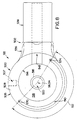
- connection hub 46 includes a main hub section 47 and two diametrically opposed bottom pivot joints 54 extending radially beyond outer surface 400 of main hub section 47.
- outer surface 400 of main hub section 47 is a cylindrical surface concentric about rotation axis 26.
- Main hub section 47 is formed to include an interior bore 404. Interior bore 404 is concentric about rotation axis 26.
- Main hub section 47 is substantially similar to a standard hub section for surgical lights with a few significant differences. Besides the obvious difference of having two diametrically opposed bottom pivot joints 54 formed integrally therewith instead of a single support arm connector, main hub section 47 includes two, instead of one, radially extending holes 402 communicating between interior bore 404 and bottom pivot joints 54. Main hub section 47 also includes a radially extending counter-bored hole 408 for receipt of a brake adjustment screw 410.
- cables 406 contain four wires, i.e., a ground wire, a wire carrying electricity at 12 volts above the potential of ground wire, a shielded cable carrying a C video signal, and a shielded cable containing a Y video signal. Different C and Y video signals can be provided to each different monitor.
- a pair of bearing assemblies 417 each includes a first tapered race 418, a second tapered race 422, and a plurality of caged rolling elements 420 positioned therebetween. Near top 412 and bottom 414 of main hub section 47, interior bore 404 is counter bored to form a shoulder 416 for receipt of first tapered race 418 on which rolling elements 420 run.
- Second tapered race 422 is formed to include a hole 424 through which a lock pin 426 is inserted to stake race 422 to shaft 430.
- Shaft 430 has this longitudinal axis of symmetry 431 on rotation axis 26 which is illustratively concentric with longitudinal axis of symmetry of hub 46.
- Rolling elements 420 of bearings run on both tapered race 422 fixed to shaft 430 and tapered race 418 held on shoulder 416 of main hub section 47 to allow main hub section 47 to rotate about rotation axis 26.
- connection hub 46 rotates about rotation axis 26 can be set by the user or assembly technician through adjustment of brake assembly 432.
- Brake assembly 432 includes a brake pad 434, metal cylindrical sleeve 436, and brake adjustment screw 410.
- brake pad 434 is in the form of a Rulon® bushing. (Rulon® is a registered trademark of Dixon Corporation).
- Brake pad 434 is press fit into metal cylindrical sleeve 436 which is formed to include a tapped hole 438.
- Shaft 430 extends through Brake pad 434.
- Brake adjustment screw 410 extends through counter bored hole 408 in main hub section 47 and is received in tapped hole 438.
- Tightening and loosening of adjustment screw 410 causes the frictional force exerted by Brake pad 434 on shaft 430 to be increased and decreased respectively.
- these frictional forces are set so that monitor arm assemblies 48 can pivot through their full range about pivot axes 56 and 58 without inducing rotation of connection hub 46 about rotational axis 26. Once monitor arms 48 have reached their limits, further rotation of monitor arm 48 will induce rotation of the entire connection hub 46 about rotational axis 26.
- Connection hub 46 is adapted to provide power and video signals to monitors 42 and 44.
- connection hub 46 includes slip ring assembly 440.
- Slip ring assembly 440 is illustrated diagrammatically, the actual internal construction being well known. Slip rings 440 are commercially available from Litton Systems, Inc., Blacksburg, Virginia, and are known in the art. Slip ring assembly 440 includes an inner plastic sleeve 442, outer plastic sleeve 444, two four-wired cables 406, and a six-wire cable 452.
- Inner plastic sleeve 442 is formed to include a keyway 443 to receive key 446 which is also received in keyway 428 formed in outer surface 429 of shaft 430 to couple inner sleeve 442 to shaft 430.
- Six-wire cable 452 runs through the interior shaft 430.
- Outer plastic sleeve 444 is formed to include a keyway 445 for receipt of a key 448 which is also received in keyway 450 formed in interior bore 404 of connection hub 46 to fix outer sleeve 444 to connection hub 46.
- slip ring assembly 440 includes seven mutually insulated sets of slip rings.
- the first set of slip rings is coupled to a ground wire in six-wire cable 452 and a ground wire in each of four-wire cables 406.
- a second set of slip rings is connected to a wire carrying electricity at 12 volts above the potential of ground in six-wire cable 452 and in both four-wire cables 406.
- the third set of slip rings is connected to a shielded wire carrying the C video signal for monitor 42 in the six-wire cable 452 and in the four-wire cable 406 running to monitor 42.
- a fourth set of slip rings is coupled a shielded wire carrying the Y video signal for monitor 42 in six-wire cable 452 and the four-wire cable 406 running to monitor 42.
- a fifth set of slip rings is coupled to a shielded cable carrying the Y video signal for monitor 44 in six-wire cable 452 and the four-wire cable 406 running to monitor 44.
- a sixth set of slip rings is coupled to the shielded wires carrying the Y video signal for monitor 44 in six-wire cable 452 and the four-wire cable 406 running to monitor 44.
- a seventh set of slip rings is coupled to the shields for all of the shielded cables in six-wire cable 452 and four-wire cable 406 to provide a shield ground for all of the video signals.
- bottom pivot joints 54 are integrally formed with main hub section 47 in connection with flange 458 to form connection hub 46.
- Each bottom pivot joint 54 includes a convex bottom wall 460, a cylindrical outer wall 462, and a flat top wall 464.
- An arcuate-shaped stop 466 extends upwardly from flat top wall 464.
- Each cylindrical outer wall 462 is concentric about a respective pivot axis 56 and 58.
- Each arcuate stop 466 extends upwardly from flat top wall 464 and radially 15° about flat top wall 464, as shown by angle 468 measured from a respective pivot axis 56 and 58 in Fig. 7.
- Bottom pivot joint 54 is also formed to include a upwardly opening interior cavity 72 defined by cylindrical inner walls 474 and cylindrical post 476.
- Each cylindrical post 476 is concentric about a respective pivot axis 56 and 58.
- a large counter bore 480 coaxial with a respective pivot axis 56 and 58, is formed in convex bottom wall 460.
- Counter bore 480 is defined by side wall 482 and wall 484.
- a radially extending slot 486 is formed in side wall 482 to receive snap legs 488 extending from convex body 490 of cap 492.
- a hexagonal bolt head-shaped hole 494 is formed in each wall 484 concentric about a respective pivot axis 56 and 58 to receive the head 496 of a hex bolt 498 to prevent hex bolt 498 from rotating with respect to bottom pivot joint 54.
- Each hex bolt 498 acts as a pivot pin and is concentric about a respective pivot axis 56 and 58.
- cylindrical post 476 extends slightly upwardly beyond flat top wall 64.
- Top pivot joint 122 is pivotally coupled to each bottom pivot joint 54.
- Top pivot joint 122 includes a housing 500 and an arm connection section 502.
- Housing 500 includes a convex top wall 504, a cylindrical side wall 506 and a flat bottom wall 508.
- An arcuate slot 510 is formed in flat bottom wall 508 and extends around flat bottom wall by an angle 512 measured from a respective pivot axis 54, 56 of approximately 195° as shown, for example, in Fig. 8. Substantially inwardly from arcuate slot 510, flat bottom wall 508 is counter bored to form an inner cylindrical wall 514 and a wall 516.
- a counter bored hole 507 extends through cylindrical side wall 506 and inner cylindrical wall 514.
- a cylindrical post 518 extends downwardly from wall 516.
- Inner cylindrical wall 514 and cylindrical post 518 are concentric about a respective pivot axis 56 and 58.
- inner cylindrical wall 514 of top pivot joint 122 has substantially the same diameter as cylindrical inner wall 574 of bottom pivot joint 54.
- An axial bore 520 coaxial with a respective pivot axis 56 and 58, extends through cylindrical post 518 and convex top wall 504.
- Convex top wall 504 is bored to form a shoulder 522 concentric about a respective pivot axis 54 and 56.
- An additional larger but shallower counter bore extends from convex top wall and is defined by step 526 and side wall 524.
- a channel 528 is formed in side wall 524 to receive snap legs 530 extending from the convex body 532 of a cap 534.
- Arm connection section 502 includes a larger diameter tapered section 536 which decreases in diameter as it extends from cylindrical side wall 506 of housing 500 and a small diameter cylindrical section 538. Arm connection section 502 extends radially from housing 500. Small diameter cylindrical section 538 is formed to include threaded holes 540 to facilitate coupling sleeve of horizontal arm 50 onto arm connection section 502. A wire bore 542 extends radially through inner cylindrical wall 514 of housing 500 and arm connection section 502.
- top pivot joint 122 During assembly of top pivot joint 122 to bottom pivot joint 54, bearings 549, formed from caged rolling elements 550 sandwiched between two thrust washers 551, are placed on shoulder 470 of bottom pivot joint 54. Hex bolt 498 is inserted through axial bore 478 until head 496 is received in hexagonal hole 494.
- a brake assembly 552 including a brake pad 554 in the form of a Rulon® bushing received in a metal cylindrical sleeve 556 and an adjustment screw 558 is attached to the shaft of hex bolt 498.
- Four-wire cable 406 is routed through hole 402, wrapped around cylindrical post 476 two times and then routed through wire bore 542 in top pivot joint 112.
- Top pivot joint 112 is then inserted over hex bolt 498 so that hex bolt 498 extends through axial bore 520.
- Adjustment screw 558 is inserted through counter bored hole 507 in cylindrical side wall 506 so that its threads are received in a threaded hole 560 in metal cylindrical sleeve 556.
- Arcuate stop 466 is received in arcuate slot 510 and flat bottom wall 508 rests on thrust washer 551 of the bearings.
- Caged needle rolling elements and two thrust washers form a thrust bearing 562 which is inserted to ride between shoulder 522 and a thrust washer 564.
- Nut 566 is attached to bolt 498.
- Cap 492 is inserted in bottom pivot joint 54 so that snap legs 488 are received in slot 486.
- Cap 534 is attached to top pivot joint 122 so that snap legs 530 are received in channel 528.
- Screws 568 are inserted through sleeve of arm and threaded, holes 540 in arm connection section 502 to couple monitor arm 48 to connection hub 46.
- Brake assembly 552 is adjusted by tightening or loosening adjustment screw 558 to increase or decrease the frictional force exerted by Brake pad 554 on hex nut 498.
- brake assembly 552 is adjusted so that top pivot joint 122 pivots more easily about pivot axis 56 and 58 than connection hub 46 rotates about rotation axis 26.
- each top pivot joint 122 pivots about a respective pivot axis 56 and 58 approximately 180° between a first limit in which first end 570 of arcuate slot 510 is contacted by first side 572 of arcuate stop 466 (shown in Fig. 10) and a second limit position wherein second end 574 of slot 510 is engaged by second side 576 of arcuate stop 466 (shown in Fig. 12).
- first limit in which first end 570 of arcuate slot 510 is contacted by first side 572 of arcuate stop 466 (shown in Fig. 10)
- second limit position wherein second end 574 of slot 510 is engaged by second side 576 of arcuate stop 466 (shown in Fig. 12).
- brake assemblies 552 and 432 are adjusted in a preferred manner, pivoting of either monitor arm 48 (not shown in Figs.
- connection hub 46 attached to arm connection section 502 between the first limit position and the second limit position will not induce rotation of connection hub 46 about rotation axis 26.
- monitor arm 48 After monitor arm 48 has been rotated in a direction until it reaches a limit position, as shown by Figs. 10 and 12, further rotation of the monitor arm 48 in the same direction will induce rotation of connection hub 46 about rotation axis 26, as shown, for example, in Figs. 11 and 13.
- Counterbalanced arms 66, 104 are pivotable arms bearing loads, shown as monitors 42 and 44 and camera 108.
- Counterbalanced arms 66, 104 like typical counterbalanced arms, include spring mechanisms which act as counterbalances to the load carried at the end of the arm opposite the pivot point.
- One problem experienced with counterbalanced arms is that after the counterbalanced arm has been pivoted so that its load is at the desired height, the weight of the load may induce the arm to pivot downwardly slightly after it is released. This unwanted travel is typically the result of the spring mechanism being improperly tensioned.
- Counterbalanced arms 66, 104 are designed to reduce this unwanted travel. Counterbalanced arm 66 will be described hereafter, it being understood that counterbalanced arm 104 is similarly constructed.
- Counterbalanced arm 66 includes a first plastic housing half 210, a second plastic housing half 212, and an arm assembly 214.
- First housing half 210 is joined to second housing half 212 to enclose arm assembly 214 to provide an easily cleanable outer surface and to prevent particulate matter and fluids from interfering with the mechanisms of arm assembly 214. It is within the scope of the disclosure to house the structural elements of the counterbalanced arm 66 within other appropriate enclosure including a cast aluminum one piece enclosure.
- Arm assembly 214 includes a load bracket 216, an upright bracket 218, a first gas cylinder 220, a second gas cylinder 222, a bottom box C-shaped link 224, a top box C-shaped link 226, a counterarm 228, a counterarm bracket 230, a slide pin 232, a counterarm bracket adjustment screw 234, and a plurality of pivot pins 236, 238, 240, 242, 244.
- Link 224 and link 226 are pivotally mounted to, and extend parallel to each other between, upright bracket 216 and load bracket 218.
- Counterarm 228 is pivotally mounted at a first end 246 to counterarm bracket 230 which is slidably mounted to load bracket 218.
- Counterarm 228 is pivotally mounted at a second end 248 to first ends 250 of gas cylinders 220 and 222 and is slidably coupled to link 224.
- the second ends 252 of gas cylinders 222 and 220 are pivotally mounted to upright bracket 216 by pivot pin 242.
- bottom link 224 includes two side walls 254 and 256 extending perpendicularly from the bottom wall 258.
- Bottom link 224 may be constructed in any of several alternative fashions, including, for example, having separate side links corresponding to side walls 254 and 256, or from a hollow rectangular tube which would include a top wall extending between side walls 254 and 256 parallel to bottom wall 258.
- Bottom link 224 has a width 278.
- Welded or otherwise mounted to side walls 254 and 256 at a first end 260 of bottom link 224 are mounting ears 262.
- Mounting ears 264 are also welded or otherwise attached to sidewalls 254 and 256 at second end 261 of bottom link 224.
- First end 260 and mounting ears 262 define a bottom opening 268 and second end and mounting ears 264 define a bottom opening 270.
- Side walls 254 and 256, of bottom link 224 are formed to include a slide slot 272 through which slide pin 232 extends to couple counterarm 228 to an intermediate portion of bottom link 224, as shown, for example, in Figs.14 and 15.
- Mounting ears 262 are formed to include mounting holes 274 through which pivot pin 238 is received to pivotally mount bottom link 224 to upright bracket 218.
- Mounting ears 264 are formed to include mounting holes 276 through which pivot pin 242 is received to pivotally mount bottom link 224 to load bracket 216. While bottom link 224 has been described as having separate mounting ears 262 and 264 welded or otherwise attached thereto, it is within the teaching of the invention for mounting ears 262 and 264 to be formed integrally with bottom link 224.
- Top link 226 includes side walls 280 and 282 and top wall 284. Side walls 280 and 282 extend upwardly from top wall 284. Top link 226 may be constructed in any of several alternative fashions, including, for example, having one or more separate L-shaped links as shown by phantom lines in Fig. 14. Top link 226 has a width 304 which is greater than width 278 of bottom link 224 facilitating assembly of bottom link 224 and top link 226 so that side walls 280 and 282 extend downwardly along the outside of side walls 254 and 256 to form an enclosure. At first end 286, offset mounting ears 288 are welded or otherwise attached to side walls 280 and 282.
- offset mounting ears 290 are welded or otherwise attached to side walls 280 and 282 of top link 226.
- Offset mounting ears 288 and first end 286 of top wall 284 define a top opening 294 at first end 286.
- offset mounting ears 290 and second end 292 of top wall 284 define a top opening 296.
- Side walls 280 and 282 are formed with the longitudinally extending recess 298 positioned to allow movement of slot pin 232 within longitudinal slide slot 272 when bottom link 224 and top link 226 are positioned adjacent each other.
- Offset mounting ear 288 is formed to include mounting holes 300 through which pivot pin 236 passes to pivotally couple first end 286 of top link 226 to upright bracket 218.
- offset mounting ear 290 is formed to include mounting hole 302 through which pivot pin 240 passes to pivotally mount second end 292 of top link 226 to load bracket 216. While top link 226 and offset mounting ears 288 and 290 are described as separate pieces welded or otherwise attached to each other, it is within the teaching of this invention to form top link 226 and offset mounting 288 and 290 as a single integral piece.
- Upright bracket 218 includes a main frame 306 and a mounting shaft 346.
- Counterbalance adjustment bracket 308 is received in main frame 306.
- Mainframe 306 includes two upwardly extending ears 310 and 312, two downwardly extending ears 314 and 316, and a cross member 318.
- Cross member 318 extends between and connects upper ears 310 and 312 and downwardly extending ears 314 and 316.
- Cross member 318 extends only partially from rear face of main frame 306 towards front face of main frame 306 to avoid interfering with pivoting action of links 224 and 226 and counterarm 228.
- Upwardly extending ears 310 and 312 are formed to include first mounting holes 322 through which pivot pin 236 passes to couple top link 226 to upright bracket 218.
- Ears 310 and 312 are also formed to include second mounting holes 324 through which pivot pin 238 passes to pivotally couple bottom link 224 to upright bracket 218.
- Mounting shaft 346 is welded or otherwise attached to rear of mainframe 306 for coupling counterbalanced arm 66 to other components of the arm assembly 48.
- Downwardly extending ears 314 and 316 are formed to include adjustment slots 326 through which pivot pin 244 extends to couple counterarm 228 to upright bracket 218.
- Counterbalance adjustment bracket 230 includes a top wall 328 and spaced apart ears 332 and 334.
- Top wall 328 is formed to include an adjustment hole 330.
- Spaced apart ears 332 and 334 extend downwardly from opposite sides of top wall 328.
- Top wall 328 and ears 332 and 334 define a channel 336 designed to receive the first end of counterarm 228.
- Counterbalance adjustment bracket 230 is received between ears 314 and 316 of main frame 306.
- Ears 332 and 334 are formed to include mounting holes 338 through which pivot pin 244 passes to pivotally mount counterarm 228 to counterbalance adjustment bracket 230 and slidably mount counterbalance adjustment bracket 230 and counterarm 228 to main frame 306.
- Cross member 318 is formed to include a threaded hole 340 within which threads of bracket adjustment screw 234 are received.
- the shaft of counter balance bracket adjustment screw 234 passes through adjustment hole 330 so that tightening of counterbalance bracket adjustment screw 234 will cause counter balance adjustment bracket 230 to move in the direction of arrow 344.
- counterbalance bracket adjustment screw 234 is loosened, the weight of the monitor and arm assembly 214 is transferred through counterarm 228 to urge counter balance adjustment bracket 230 downwardly. This movement allows a user to adjust the tension exerted by gas cylinders 220 and 222 at an optimum level to minimize unwanted travel after vertically positioning monitor or camera.
- Second end 258 of counterarm 228 is formed to include a yoke 352.
- Ears 354 of yoke 352 are formed to include mounting holes 356 through which slide pin 232 passes to slidably couple counterarm 228 to bottom link 224 and pivotally mount counterarm 228 to first end 250 of first and second gas cylinders 220 and 222.
- Load bracket 216 includes mounting shaft 358 and frame 360.
- Frame 360 is formed to include ears 362 and 364 and cross member 366.
- Mounting shaft 358 is welded or otherwise attached to frame 360 and ears 362 and 364.
- Ears 362 and 364 are formed to include mounting holes 368 through which pivot pin 242 passes to couple second end of bottom link 224 to load bracket 216, and mounting holes 370 through which pivot pin 240 passes to pivotally mount second end of top link 226 to load bracket 216.
- Second ends 252 of gas cylinders 220 and 222 are pivotally coupled by pivot pin 242 to load bracket 216.
- Plastic spacers 372 are disposed on pivot pin 242 between ear 364 and second end 252 of gas spring 224, between second end 252 of gas spring 222 and second end 252 of gas spring 220, and between second end 252 of gas spring 220 and ear 364, to maintain alignment of gas springs 220 and 222.
- Counterbalanced arm 66 can move between a lower position (shown in phantom lines in Fig. 15) in which slide pin 232 is nearest second end 374 of slot 272 and an upper position (shown in solid lines in Fig. 15) wherein slide pin 232 is nearest first end 376 of slot 272.
- Gas cylinders 220 and 222 cooperate with friction between mounting ears 262 and 288 and load bracket 218 and mounting ears 264 and 290 and upright bracket 216 to allow counterbalanced arm 66 to be stopped and held in any position between the lower limit and upper limit.
- An unillustrated alternative, or additional, device to facilitate elimination of unwanted travel in counterbalanced arm 66 is a brake mechanism similar in construction and operation to the brake mechanisms in main hub 47 and top pivot joint 122.
- the brake mechanism may be coupled to bottom link 224 and either or both pivot pins 238 and 242.
- the brake mechanism includes a brake pad in the form of a Rulon® bushing received in a metal cylindrical sleeve through which pivot pins 238 and/or 242 pass, a flange extending inwardly from either of sidewalls 254 and 256 of bottom link 224, and an adjustment screw 384.
- the inwardly extending flange is formed to include a hole through which the shaft of adjustment screw passes and metal cylindrical sleeve is formed to include a threaded hole in which the threads of shaft of adjustment screw are received.
- Fig. 4 illustrates a fixed height monitor arm assembly 180.
- Those elements referenced by the same reference numeral in Fig. 4 as was used to identify a corresponding element in Fig. 1-3 perform the same or similar function as the corresponding element in Figs. 1-3.
- Lower vertical arm section 62 and counterbalanced arm 66 are replaced by an offset or S-shaped section 182 including an upper section 184 rotatably coupled to arm section 60 about axis 64 as illustrated by double-headed arrow 186.
- a central, horizontal arm section 188 extends between upper arm section 184 and a lower arm section 190.
- a mounting assembly 192 couples the arm portion 182 to the monitor 42.
- a handle 194 is coupled to a monitor support 196.
- a shaft 198 is rotatably coupled to arm section 190 about axis 200 as illustrated by double-headed arrow 202.
- Arm 198 is also coupled to support 196 for pivotable movement about axis 204 as illustrated by double-headed arrow 206.
- OR suites in which the healthcare staff may wish to perform operations to be filmed or in which video images may be useful in facilitating the surgical operation.
- OR suites will be utilized at the same time.
- surgical procedures will be performed that will require two cameras and only a single monitor or three monitors and no camera.
- a surgical theater system 10 includes either a multi-purpose arm 648 configured to removably receive a camera 108, and/or a monitor 42 and 44 or a multi-purpose receptacle 745 configured to receive a camera arm 790 or a monitor arm 748.
- a multi-purpose arm 648 is provided configured to support either a monitor mount 649 or a camera mount 647.
- a multi-purpose receptacle 745 is provided configured to support either a monitor arm 748 or a camera arm 790.
- the multi-purpose arm 648 and the multi-purpose receptacle 745 each include a mechanical connector for mechanically coupling either a monitor mount 649 or a monitor arm 748 or a camera mount 647 or a camera arm 790 to the multi-purpose arm 648 or multipurpose receptacle 745.
- Each multi-purpose arm 648 and multi-purpose receptacle 745 also includes one or more standard video couplings located adjacent the mechanical connector for attachment to the video lead coupled to a camera 108 and/or a monitor 42 and 44.
- a health care facility upon installation of a surgical theater system in accordance with the present invention is capable of reconfiguring the surgical theater system to provide as many monitors 42 and 44, and cameras 108, or combinations of monitors 42 and 44, and cameras 108 as the apparatus has multi-purpose arms 648 or multi-purpose receptacles 745. It is within the teaching of the disclosure for multi-purpose arms 648 and multi-purpose receptacles 745 to be configured to receive other device mounts and arms, such as, for example, surgical lighthead mounts and arms, respectively.
- Figs. 16 and 17 illustrate two alternative embodiments of such a surgical theater system 10, however, additional non-illustrated embodiments providing a single or a plurality of multi-purpose arms or receptacles or multi-purpose arms or receptacles providing for disconnection at different locations are within the scope of the invention as presently perceived. It is within the scope of the invention to provide a plurality of similarly configured surgical theater systems 10 throughout a healthcare facility between which monitors 42 and 44 and/or cameras 108 may be exchanged.
- Fig. 16 illustrates a first configurable surgical light apparatus having a pair of surgical light heads 18, 20 coupled to a central hub 12, and a pair of multi-purpose arms 648 coupled to pivot joints 54 on hub 12.
- Surgical light support arms 28 include horizontally extending sections 30 and vertically extending sections 32.
- Vertically extending arm sections 32 include upper and lower sections 34 and 36 so that the vertical sections 32 are rotatable about an axis 38 (shown in Fig. 1).
- a counterbalanced arm 40 is pivotally coupled to vertical arm section 32 for supporting surgical lights 18 and 20.
- Multi-purpose hub 646 is similar to connection hub 46 and identical or similar reference numerals will be used to identify identical and similar components. It is to be understood that the description of connection hub 46 set forth above is generally applicable to multi-purpose hub 646. While multi-purpose hub 646, illustrated in cross-section in Fig. 18, is illustrated as being used only with multi-purpose arm assembly 648 and multi-purpose receptacle 745, multi-purpose hub 646 is adaptable for use with any of the illustrated surgical theater systems. Similarly, connection hub 46 is adaptable for use with any of the illustrated surgical theater system embodiments.
- Multi-purpose hub 646 includes a slip ring assembly 645 configured for attachment to the lower end of shaft.
- Cable 653 extends internally through shaft 430 and is electrically coupled to a first end of slip ring assembly 645.
- cable 653 includes twenty-eight wires which carry power, ground and video signals to or from two separate video devices.
- Two cables 607 are electrically coupled to second end of slip ring assembly 640.
- Each cable 607 includes fourteen wires which carry power, ground and video signals to or from a single video devices.
- Slip ring assembly 645 includes 28 sets of slip rings to transfer the power, ground and video signals between the wires of cable 653 and cable 607.
- slip ring assembly 645 is commercially available from AirFlite, as part number #100164-001.
- Multi-purpose hub 646 includes a pair of diametrically opposed longitudinally extending holes 603 cast or machined in the main hub section 47. Each longitudinal hole 603 intersects with a respective radially extending hole 402 to permit passage of cables 603 extending from second end of slip ring assembly 645 into lower pivot joint 54 and out of distal end of wire bore 542 of arm connection section 502 of top pivot joint 122. Each cable 607 terminates in an electrical connector 643 configured for attachment to an arm cable coupled to a video device.
- Each multi-purpose arm 648 is identical to the other and is very similar to monitor support arm assembly 48. Thus, except where otherwise noted below, the description of monitor support arm assembly 48 above accurately describes multi-purpose arm 648 and will not be repeated. Components in multi-purpose arm 648 that are similar to corresponding components in monitor support arm assembly 48 will be identified with similar reference numerals.
- a multi-purpose arm assembly 648 includes a bent arm or first segment having a horizontal arm section 650 and a vertical arm section 652.
- Horizontal arm sections 650 are coupled to bottom pivot joints 54 which extend away from a main hub section 47 of connection hub 646. Therefore, the horizontal arm sections 650 are pivotable about pivot axes 56 and 58 (shown in Fig. 1) which are spaced apart from the pivot axis 26 (shown in Fig. 1) of central hub 12.
- Vertical arm sections 652 of multi-purpose arm assemblies 648 illustratively include first and second sections 660 and 662.
- the second vertical section or extension arm 662 is rotatable relative to the first vertical section 660 about axis 64 (Shown in Fig. 1).
- Counterbalanced arms 666 are pivotally connected to second vertical section 662 by a pivot connection 668 located at the proximate end of counterbalanced arm 666.
- a second pivot connection 672 is located at the distal end of counterbalanced arm 666.
- Multi-purpose arms 648 include a coupling 651 coupled to pivot connection 672 at the distal end of a counterbalanced arm section 666 of the multi-purpose arm 648.
- a monitor 42 is shown mounted to the first multi-purpose arm 648 via a monitor mount 649.
- a camera coupled to a camera mount 647 and a second monitor 44 coupled to a monitor mount 649 are shown disconnected from the second multi-purpose arm 648.
- Camera mount 647 and both monitor mounts 649 are each provided with one half of a mechanical quick disconnect coupling 655 of a known type configured to connect to a second half of a mechanical quick disconnect coupling 651 mounted to pivot connection 672 on the distal end of counterbalanced arm section 666 of multi-purpose arm 648.
- Monitor mount 649 includes a horizontal arm 670 coupled to hub 674. Hub 674 is coupled to first half of connector 653. A vertical arm 676 is coupled to horizontal arm section 670. A monitor mounting arm 678 has a first end rotatably coupled to a hub 682 of vertical arm 676. A handle 84 is coupled to the first end of monitor mounting arm 678. Illustratively duplicate toggle switch 606 is mounted to handle 84. A second end of mounting arm 678 is coupled to a monitor support plate (not shown) mounted to monitor 42 and 44.
- the description of the movement of monitor mounting arm assembly 48 set forth above accurately describes the movement of multi-purpose arm 648 when monitor mount 649 is coupled thereto and will not be repeated.
- Cables run through monitor mount 649 to provide power and video signals to monitor 42 and 44. These cables terminate in an electrical connector (not shown) located adjacent to mechanical coupling 653 for coupling cables of monitor mount 649 to a connector (not shown) located adjacent mechanical coupling 651 of multi-purpose arm 648. Electrical connectors facilitating the coupling of video equipment are well known in the art and are therefore not described.
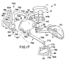
- Camera mount 647 includes a first half of a quick disconnect coupling 655 coupled to hub 714.
- Camera mount 647 includes a camera mounting arm 710 rotatably mounted to coupling 653 by hub 714.
- a pan/tilt mechanism housing 711 is coupled to mounting arm 710 and camera 108.
- Housing 711 Housed in housing 711 are motors and mechanisms permitting remote panning and tilting of camera 108.
- Camera 108 includes internal mechanisms, motors and controls to facilitate focus adjustment, zooming, iris adjustment, and white balance adjustment.
- Extending downwardly from camera hub 711 is handle 713 including on/off switch 715 electrically coupled to turn camera 108 on and off.
- handle 713 includes a longitudinal axis 717.
- Handle 713 is mounted to camera hub 711 for pivotal movement about the longitudinal axis 717. Pivotal movement of handle 713 about longitudinal axis 717 actuates an actuator coupled to the zoom mechanism of the camera 108. Preferably, handle 713 also includes an actuator (not shown) such as a button to adjust the focus of the camera 108. It is within the teaching of the present invention for handle 713 to be a sterile handle so that a surgeon or other operating room personnel can turn the camera on and off during an operation. It is understood that any suitable camera 108 may be used.
- Cables run through camera mount 647 to provide power, pan, zoom, tilt, focus, white balance, and iris signals to, and video signals from camera 108. These cables terminate in an electrical connector (not shown) located adjacent to mechanical coupling 653 for coupling cables of camera mount 647 to a connector (not shown) located adjacent mechanical coupling 651 of multi-purpose arm 648.
- Multi-purpose arm 648 is provided with radial holes to permit passage of cables containing thirty-two wires (not shown). Twenty of these thirty-two wires provide power, pan, zoom, tilt, focus, white balance, and iris signals to, and video signals from camera 108, when camera mount 647 is attached to multi-purpose arm 648. It should be understood that all cameras 108 attached to multi-purpose arm will not have mounts and mechanisms facilitating remote control of panning, zooming, tilting, white balancing, and iris adjustment. The remaining 12 wires provide power and video signals to a monitor 42 and 44 when a monitor 42 and 44 is attached to multi-purpose arm 648.
- multi-purpose arm 648 may be provided with standard brake mechanisms within counterbalanced arm section 666 to lock counterbalanced arm 666 at a location prior to removal of camera mount 647 or monitor mount 649 and replacement with another camera mount 647 or monitor mount 649.
- quick disconnect coupling 651 may be provided with mechanisms prohibiting removal of a camera mount 647 or monitor mount 649 unless counterbalanced arm 666 is placed in its uppermost raised location as shown in Fig. 16.
- Other mechanisms and methods of attachment and detachment of mounts 647 and 649 which inhibit a rapid movement of counterbalanced arm 666 to its uppermost raised location upon removal of a camera mount 647 or monitor mount 649 are within the scope of the invention as presently perceived.
- monitor mount 649 and camera mount 647 may include ballast so that the weight of camera mount 647 and monitor mount 649 can be adjusted to a selected weight for which the counterbalanced arm 666 is calibrated. It is also within the teaching of this invention as presently perceived to provide counterbalanced arm 666 with calibration mechanisms to adjust counterbalanced arm 666 for proper operation when coupled to loads of different weights.
- Fig. 17 illustrates a second configurable surgical theater system 10 having a pair of surgical light heads 18, 20 coupled to a central hub 12, and a pair of multi-purpose receptacles 745 (only one of which is visible in Fig. 17) configured to be coupled at one end to a monitor arm 748 or a camera arm 790 and at the other end to a pivot joint 54 on hub 12.
- Surgical light support arms 28 include horizontally extending sections 30 and vertically extending sections 32.
- Vertically extending arm sections 32 include upper and lower sections 34 and 36 so that the vertical sections 32 are rotatable about an axis 38 (shown in Fig. 1).
- a counterbalanced arm 40 is pivotally coupled to vertical arm section 32 for supporting surgical lights 18 and 20.
- Monitor 42 and/or camera 108 are coupled to multi-purpose hub 646 by a dedicated monitor arm 748 or a dedicated camera arm 790 respectively coupled to multi-purpose receptacle 745.
- Each multi-purpose receptacle 745 is substantially identical to the other.
- Multi-purpose receptacles 745 include a coupling 751 at their distal ends and are coupled at their proximate ends for pivotal movement about pivot joint 54.
- a monitor 42 is shown mounted to the first multi-purpose receptacle 745 via a monitor arm 748 and a camera 108 coupled to a camera arm 790 is shown disconnected from the second multi-purpose receptacle 745.
- a second monitor arm 748 could be coupled to second multi-purpose receptacle 745 to provide a surgical theater system with two monitors.
- a second camera arm could be coupled to the first multi-purpose receptacle to provide a surgical theater system with two cameras.
- Camera arm 790 and monitor arm 748 are each provided with one half of a mechanical coupling 753 configured to connect to a second half of a mechanical coupling 751 mounted to multi-purpose receptacle 745.
- the proximate end of monitor arm 648 and camera arm 790 slide over the arm connection section 502 of top pivot joint 122 and are bolted thereto to provide mechanical connection. It will be understood that it is within the teaching of the disclosure to provide arm connection section 502 of top pivot joint 122 with one half a standard mechanical quick disconnect connection and to provide the proximate ends of monitor arm 748 and camera arm 790 with the other half of a standard mechanical quick disconnect section.
- Monitor arm 748 is very similar to monitor support arm assembly 48. Thus, except where otherwise noted below, the description of monitor support arm assembly 48 above accurately describes monitor arm 748 and will not be repeated. Components in monitor arm 748 that are similar to corresponding components in monitor support arm assembly 48 will be identified with similar reference numerals.
- monitor arm 748 includes a bent arm or first segment having a horizontal arm section 750 and a vertical arm section 752.
- Horizontal arm section 750 includes a first half of a mechanical coupling at its proximate end configured for coupling to a second half of a coupling 751 at distal end of multi-purpose receptacle 745.
- multi-purpose receptacle 745 is coupled at its proximate end to bottom pivot joints 54 which extend away from a main hub section 47 of connection hub 46. Therefore, the horizontal arm sections 750 are pivotable about pivot axes 56 and 58 (shown in Fig. 1) which are spaced apart from the pivot axis 26 (shown in Fig. 1) of central hub 12.
- Vertical arm sections 752 of monitor arm 748 illustratively includes first and second sections 760 and 762.
- the second vertical section or extension arm 762 is rotatable relative to the first vertical section 760 about axis 64.
- Counterbalanced arms 766 are pivotally connected to second vertical section 762 by a pivot connection 768 located at the proximate end of counterbalanced arm 766.
- a second pivot connection 772 is located at the distal end of counterbalanced arm 766.
- a horizontal arm 770 coupled by hub 774 to second pivot connection 772 of counterbalanced arm 766.
- a vertical arm 776 is coupled to horizontal arm section 770.
- a monitor mounting arm 778 has a first end rotatably coupled to a hub 782 of vertical arm 776.
- a handle 84 is coupled to the first end of monitor mounting arm 778.
- Illustratively duplicate toggle switch 606 is mounted to handle 84.
- a second end of mounting arm 778 is coupled to a monitor support plate 786 mounted to monitor 42.
- monitor mounting arm assembly 48 The description of the movement of monitor mounting arm assembly 48 set forth above accurately describes the movement of monitor arm 748 and multi-purpose receptacle 745 when monitor arm 748 is coupled thereto and will not be repeated.
- Cables run through monitor arm 748 to provide power and video signals to monitor 42, which illustratively include cable 761, cable 763, cable 765, cable 767.
- cable 761 terminates in an electrical connector 759 located adjacent to mechanical coupling 753 for coupling to connector 643 of cable 607 located adjacent mechanical coupling 751 of multi-purpose receptacle 745.
- slip ring assembly 769 mounted frictionally mounted in lower arm 62 of vertical arm 52 adjacent to the point where lower arm is rotatably coupled to upper arm.
- slip ring assemblies 769 and 771 are available from Litton Systems, Inc., Blacksburg, Virginia, as part number AC6319. Such slip ring assemblies include 14 sets of slip rings allowing two power and twelve signals to be transferred between cables on opposite sides of rotating components.
- slip ring assembly 769 is coupled to a first end of cable 763 which runs through lower arm 762 and counter balanced arm 766.
- Second end of cable763 is coupled to a first end of slip ring assembly 771.
- Slip ring assembly 771 is frictionally mounted within hub774 adjacent to the point where hub 774 is rotatably mounted to second pivot connection 772 of counterbalanced arm 766.
- Second end of slip ring assembly 771 is electrically coupled to first end of cable 765 which extends through hub 774, horizontal arm 770, vertical arm 776 and hub 772.
- the other end of cable 765 is coupled through switch 606 to one end of cable 767. Cable 767 extends through monitor mounting arm 778 and terminates in a plurality of connectors 773 for coupling to a monitor.
- Camera arm 790 is similar to camera mounting arm assembly 90 so similar reference numerals will be used for similar components.
- the major differences between camera arm 790 and camera arm mounting assembly 90 are the cables running through the camera arm 790 and camera mounting arm assembly 90 and the fact that the camera arm 790 includes couplings for mounting to multi-purpose receptacle 745 rather than being mounted to a separate camera hub 94 like camera mounting arm assembly 90.
- Camera arm 790 also includes a mechanism housing 811 in which remotely operable pan/tilt motors and mechanisms are housed.
- Camera arm 790 includes a horizontal arm section 792 having a proximate end including a first half of a mechanical coupling 753 configured to mate with second half of mechanical coupling 751 of multi-purpose receptacle 745 mounted to pivot joint 54 of hub 646 of central hub 12.
- a vertical arm section 796 is coupled to distal end of horizontal arm section 792.
- Vertical section 796 includes a first, upper section 798 and a second, lower arm section 800 rotatably coupled to arm section 798 about axis 102 (shown in Fig. 1).
- a counterbalanced arm 804 is coupled to lower vertical section 800 by a pivot connection (not shown).
- Shaft 812 is pivotally connected to counterbalanced arm 804 by pivot connection 816.
- Camera mounting arm 810 is rotatably mounted on shaft 812 by hub 814.
- a pan/tilt mechanism housing 811 is coupled to mounting arm 810 and camera 108.
- Housing 811 Housed in housing 811 are motors and mechanisms permitting remote panning and tilting of camera 108.
- Camera 108 includes internal mechanisms, motors and controls to facilitate focus adjustment, zooming, iris adjustment, and white balance adjustment.
- Extending downwardly from camera housing 811 is handle 813 including on/off switch 815 electrically coupled to turn camera 108 on and off.
- handle 813 includes a longitudinal axis 817. Handle 813 is mounted to camera hub 811 for pivotal movement about the longitudinal axis 817.
- handle 813 Pivotal movement of handle 813 about longitudinal axis 817 actuates an actuator (not shown) coupled to the zoom mechanism of the camera 108.
- handle 813 also includes an actuator (not shown) such as a button to adjust the focus of the camera 108. It is within the teaching of the present invention for handle 813 to be a sterile handle so that a surgeon or other operating room personnel can turn the camera on and off during an operation. It is understood that any suitable camera 108 may be used.
- Cables run through camera arm 790 to provide power, pan, zoom, tilt, focus, white balance, and iris signals to, and video signals from camera 108. These cables terminate in an electrical connector (not shown) located adjacent to mechanical coupling 753 for coupling cables of camera arm 790 to a connector (not shown) located adjacent mechanical coupling 751 of multi-purpose receptacle 745. Slip rings of the type described with regard to monitor arm 748 facilitate rotation of components of camera arm 790 relative to each other.
- Multi-purpose receptacle 745 is provided with radial holes to permit passage of cables therethrough for coupling to cables within camera arm.
- such cable contains fourteen wires (not shown). These wires provide power, pan, zoom, tilt, focus, white balance, and iris signals to, and video signals from.camera 108, when camera arm 790 is attached to multi-purpose receptacle 745 and an indicator signal to indicate whether the cable is carrying signals for a monitor or camera. It should be understood that all cameras 108 attached to camera arms will not have mounts and mechanisms facilitating remote control of panning, zooming, tilting, white balancing, and iris adjustment.
- a surgical theater system is provided with a video monitor mounted to an arm extending from the hub of the surgical theater system.
- the monitor is adapted to display images received from a plurality of video inputs coupled to a plurality of video devices.
- a controller is coupled between the plurality of video inputs and the monitor to control the image that is displayed on the monitor.
- the controller may include switches mounted away from, but coupled to, the surgical theater system hub and switches mounted to the monitor arm or the monitor for selecting the video input providing the image displayed by the monitor.
- Controls facilitate selectively displaying images from a plurality of video devices 592.
- Each of the embodiments includes a selector control panel 585 and 636 having an input control panel 608 and 638 and an output panel 610.
- Each input control panel 608 and 638 includes a plurality of connectors 586, 588, 590 configured for coupling to a plurality of video devices 592 providing a video feed, selector buttons 594, 640, 642 for selecting which connector 586, 588, 590 is active, and indicator lights 596, 598, 600 indicating the active connector.
- Each output panel 610 includes a plurality of connectors 616, 618, 620 configured to be coupled to a monitor or video display device located remotely from the surgical theater system (not shown).
- Each embodiment allows a video feed from a camera 108 mounted to the surgical theater system 10 or a remote video device to be displayed on the monitors 42 and 44 of the surgical theater system or on remote monitors or video displays coupled to the output panel 610.
- a remotely mounted selector control panel 585 includes a multi-channel input panel 608, an output panel 610, and monitor input selector panel 595.
- the multi-channel input panel 608 is coupled to one or two monitors 42 and 44 coupled to the hub of the surgical theater system.
- four channels 581-584 are provided through which video signals from a plurality of video devices 592 are transmitted.
- selector device 580 includes a selector control panel 585, a power supply 622, and a switcher 632.
- Selector control panel 585 includes a multi-channel input selector panel 608 having four channels, referred to hereinafter as channels 1-4 (581, 582, 583, 584 respectively).
- Each channel 581-584 includes three different types of video connectors, i.e., a y-c connector 586 (shown as squares in Fig. 24), a composite connector 588 (shown as triangles in Fig. 24), and an RGB connector 590 (shown as circles in Fig. 24), to facilitate coupling a wide variety of video input devices 592 to each channel 581-584.
- Each channel 581-584 includes a selector switch 594 permitting the user to select between available connectors 586, 588, 590 to designate an active connector providing the video feed for that channel.
- the connector of the video device 592 is coupled to the similarly configured connector 586, 588, 590 of the channel 581-584, as shown, for example, in Fig. 24.
- the appropriate connector 586, 588, 590 is selected as the active connector corresponding to the connector 586, 588, 590 to which the video device 592 is coupled by toggling of the selector switch 594.
- Indicator lights 596, 598, 600 are provided adjacent to each connector 586, 588, 590 of each channel 581-584. When a specific connector 586, 588, 590 is selected as the active connector, the indicator light 596, 598, 600 corresponding to that connector 586, 588, 590 is lit.
- channels 581-584 each having three connectors 586, 588, 590, up to twelve video devices 592 can be coupled to the surgical theater system 10 although only one video device 592 per channel 581-584 will have its video feed available for display on a monitor 42 and 44 of the surgical theater system 10 at any time. While the illustrated embodiment, shows three inputs (each input corresponding to a connector 586, 588, 590) per channel and four channels 581-584 in the system, it is within the scope of the disclosure as currently perceived to provide a selector system with fewer or more connectors or channels.
- the illustrated selector control panel 585 may be located remotely from the surgical theater system 10. It is within the teaching of the disclosure for the selector control panel 585 to be mounted to a wall of the OR suite, to a separate boom in the OR suite, to some other location remote from the surgical theater system 10, or to the surgical theater system 10. For purposes of this description, the selector control panel 585 will be described as being mounted to a wall of the OR suite at a location remote from the surgical theater system 10. As previously described, remotely mounted controls for the surgical lights are often mounted to walls of surgical suites and it is within the teaching of this invention to mount the selector control panel 585 in the vicinity of the wall mounted light controls.
- Monitor input selector panel 595 allows a user to choose one of the four channels 581-584 to be the active channel having its video feed displayed on a first or "A" monitor 42 of the surgical theater system 10 and to choose the same channel 581-584, or another of the four channels 581-584, as the active channel to have its video feed displayed on a second or "B" monitor 44 of the surgical theater system 10.
- monitor input selector panel 595 includes an "A" monitor selector sub-panel 597 and a "B" monitor selector sub-panel 599. Each sub-panel 597 and 599 is provided with a selector button 604 and a channel selector LED array 602 including four LED's each of which is associated with one of the four channels 581-584.
- pushing selector switch 604 causes the active channel for the monitor associated with the sub-panel 597 and 599 to toggle through the available channels.
- the appropriate LED in the channel selector LED array 602 is illuminated to indicate the active channel for the sub-panel 597 and 599.
- channel 1 581 is the active channel for the "A" monitor 42 as indicated by the illumination of the LED associated with channel 1 of the LED array 602 of sub-panel 597
- channel 3 583 is the active channel for the "B" monitor 44 as indicated by the illumination of the LED associated with channel 3 of the LED array 602 of sub-panel 599.
- a duplicate selector switch 606 is located in the sterile handle 84 of each monitor 42 and 44, as shown, for example, in Figs. 24,16 and 17.
- This duplicate selector switch 606 allows a surgeon or some other operating room personnel to select which image is visible on the monitor 42 and 44 to which the handle 84 is attached without moving away from the monitor 42 and 44. Pushing the duplicate switch 606 toggles through each available channel 581-584 to alter the active channel for the associated monitor 42 and 44 and induces the associated LED for the active channel of the LED array 602 to be illuminated on the associated sub-panel 597 and 599.
- selector control panel 585 also includes an output panel 610 allowing the images on any channel 581-584 to be provided to a remote monitor, VCR, printer, computer, or other device if desired. Included in the output panel 610 are an "A" monitor output sub-panel 612 and an input 1 auxiliary output sub-panel 614. Each sub-panel 612 and 614 includes a plurality of connectors, illustrated as a y-c connector 616, a composite connector 618, and an RGB connector 620.
- the connectors 616, 618, 620 of the "A" monitor output sub-panel 612 are coupled to the video signal selected for the "A" monitor 42 allowing the same image to be displayed on a remote monitor as is being displayed on the "A" monitor 42 of the surgical theater system 10.
- the "A” monitor 42 will usually be selected by the surgeon as the main monitor so that the "A" monitor output is used for another peripheral or remote monitor or support device.
- the "A" monitor output sub-panel 612 includes three indicator lights 626, 628, 630, such as LEDs, associated with connectors 616, 618, 620 respectively to indicate the type of signal which is being transmitted and therefore the active connector. If a slave monitor is coupled to the "A" monitor output sub-panel 612, the slave is preferably coupled to all three output connectors 616, 618, 620 to guarantee that an image will always appear on the slave monitor.
- the connectors 616, 618, 620 of input 1 auxiliary output sub-panel 614 are shown to be a direct feed from the primary input 1 present on channel 1 581. Any device that is plugged into connectors 586, 588, 590 of channel 1 581 will feed a signal directly to the connectors 616, 618, 620, respectively, of auxiliary output sub-panel 614.
- the output of sub-panel 614 can be used as an emergency output since it is a direct signal from the input panel 608 and doesn't travel through the arm system to the monitor. If anything fails in the monitor 42 and 44 or arm system, a signal is still available from the auxiliary output sub-panel 614.
- power supply 622 to the surgical theater system including the first monitor 42 and second monitor 44, and the selector panel 585 is mounted in a ceiling box 624.
- Power supply 622 is a low voltage medical grade power supply producing twelve volts. Illustratively, power supply 622 is made by International Power Sources, Inc., Holliston, MA, 01746 as model # PM200-13C.
- a switcher 632 is also mounted in the ceiling box 624. Switcher 632 is electrically coupled to first monitor 42, second monitor 44, duplicate switches 606 on the handle 84 of each monitor 42 and 44, input panel 608, wall selector control panel 595, and "A" monitor output sub-panel 612. Power to switcher 632 is supplied by power supply 622.
- Video signals from the active input of each channel 581-584 are electrically coupled to switcher 632 through video bus 634.
- the channel 1 input is directly coupled to the auxiliary output sub-panel 614.
- inputs are available from four channels 581-584, each of which may be coupled to as many as three input devices 592. It is within the scope of the disclosure as presently perceived to configure each channel to receive as few as one video input or more than three video inputs.
- switcher 632 selects from the video signals received from inputs and routes video signals to the "A" monitor 42, "B” monitor 44, and output sub-panel 612.
- Output sub-panel 612 receives the same video feed as "A” monitor 42.
- "B" monitor 44 may receive the same or a different video feed as "A” monitor 42.
- Selector device 636 includes an alternative dedicated input panel 638 and an output panel 610.
- Output panel 610 of selector device 636 is substantially identical to output panel 610 of selector device 580 described above except for the connection of output sub-panel 614. Nevertheless, identical reference numerals will be used in describing output panel 610 of selector device 636 as were used in describing output panel 610 of selector device 580.
- Input panel 638 includes three differently configured connectors (a y-c connector 586, a composite connector 588, and an RGB connector 590), an "A" monitor selector button 640, a “B” monitor selector button 642 and two sets of three indicator lights 596, 598, 600 associated with connector 586, 588, 590. Actuation of "A" monitor selector button 640 selects one of the three connectors 586, 588, 590 as the active connector providing the video feed to "A" monitor 42 and "A" monitor output sub-panel 612.
- Actuation of "A" monitor selector button 640 also induces the appropriate one of the three “A” monitor indicator lights 596, 598, 600 to indicate which connector 586, 588, 590 respectively is the active connector for "A” monitor 42.
- Actuation of "B” monitor selector button 642 selects one of the three connectors 586, 588, 590 as the active connector providing the video feed to "B” monitor 44.
- Actuation of "B” monitor selector button 642 also induces the appropriate one of the three “B” monitor indicator lights 596, 598, 600 to indicate which connector 586, 588, 590 respectively is the active connector for "B” monitor 44.
- Output panel 610 of selector device 636 includes "A" monitor output sub-panel 612 and Auxiliary output sub-panel 614.
- "A" monitor output sub-panel 612 is identical to "A" monitor output sub-panel 612 of selection device 580 and receives the video feed being sent to "A" monitor 42.
- Auxiliary output sub-panel 614 of selector device 636 is similar to channel 1 auxiliary output sub-panel 614 of selector device 580 in that it is directly coupled to the input panel 638, however, auxiliary output sub-panel 614 may receive any video feed which is live.
- Auxiliary output panel sub-panel 614 includes an indicator light 644, such as an LED to indicate that the system is powered on.
- selector device 580 and selector device 636 are intended for use with a surgical theater system 10 including a first and second monitor 42 and 44.
- selector device 636 can be mounted in similar locations as selector device 580 and can be coupled to a surgical theater system 10 in a similar manner as is shown in Fig. 24.
- Selector device 636 has fewer channels than selector device 580. Because selector device 636 includes only one of each type of connector 586, 588, 590, the number and type of video devices 592 which may be coupled to a surgical theater system 10 is more limited with selector device 636 than with selector device 580. In the illustrated configuration, without an external splitter, only three remote video devices 592, each having a different type of connector may be coupled to the monitors 42 and 44 of a surgical theater system 10 when selector device 636 is used.
- Cameras are used in operating rooms as a means of networking with the rest of the world.
- the camera has now become the vehicle by which surgeons can consult with each other during live procedures.
- surgeons it is not uncommon for surgeons to consult with each other from different parts of the world during a case (commonly referred to as ' Telesurgery ').
- many cameras used in surgical suites include or are coupled to microphones and speakers permitting audio as well as video signals to be recorded and transmitted.
- clinical educators require interactive filming capabilities that can be controlled remotely from the classroom.
- Such procedures are either recorded for critique at a later date or simply observed 'real time' for teaching. Surgeons routinely record procedures and edit the content for presentation at a conference. More surgical procedures are being recorded for future reference should the outcome of the surgery be questioned.
- camera 108, camera arm 790 and camera mount 647 may include mechanisms and drives facilitating remote control of panning, zooming, tilting, white balancing, and iris adjustment.
- a camera wall control panel 820 as well as a wireless remote control 822 is provided, as shown, for example, in Figs. 27 and 28. It is also envisioned, although not illustrated, that a wired remote control be provided to facilitate control of the camera 108 from a remote conference room.
- Such a wired remote control will include a control panel having buttons similar to those illustrated in Fig. 27.
- Camera 108 and its mounting mechanism may be manually positioned enabling the doctor to point the camera at the surgical sight.
- a pan/tilt mechanism 711 and 811 allows the camera to be remotely tilted up or down and panned left or right by after initial set up.
- the degree of freedom of pan and tilt remotely controlled motion may be limited such as by plus or minus forty-five degree of the manually adjusted home position.
- Each control panel 820 and remote control 822 is provided with an on/off button 824 and 826, two pan buttons 828 and 830, two tilt buttons 832 and 834, a home position button 836, a pause button 838, two focus buttons 840 and 842, two zoom buttons 844 and 846, two iris buttons 848 and 850, and either two white balance buttons 852 and 854 or a white balance set button 856.
- an on/off button 824 and 826 two pan buttons 828 and 830, two tilt buttons 832 and 834, a home position button 836, a pause button 838, two focus buttons 840 and 842, two zoom buttons 844 and 846, two iris buttons 848 and 850, and either two white balance buttons 852 and 854 or a white balance set button 856.
- surgeon or other OR personnel may manually adjust camera mount 647 or camera arm 790 to point camera 108 at an initial position, such as the surgical sight.
- the mechanisms controlling the pan and tilt are adjusted to a central position half way between their limits of travel, such position being referred to herein as the home position, then actuation of the home button 830 causes the camera to return to pointing at the surgical sight (or any other initial position).
- Each On/Offbutton 824 and 826 is coupled to a switch that controls the supply of power to the camera 108.
- Each pan button 828 and 830 is coupled to a motor control circuit for controlling the motor which actuates panning of the camera 108.
- the pan left button 828 is actuated, the pan motor is controlled to induce the camera mount to rotate the field of view of the camera 108 to the left.
- the pan right button 830 is actuated, the pan motor is controlled to induce the camera mount to rotate the field of view of the camera 108 to the right.
- Actuation of the tilt up button 832 controls the tilt motor to induce the field of view of the camera 108 to rotate upwardly.
- Actuation of the tilt down button 834 controls the tilt motor to induce the field of view of the camera 108 to rotate downwardly.
- the two focus buttons 840 and 842 are coupled to internal motors of the camera 108 that control the position of the lens in order to adjust the focus of the camera 108. Pushing the first focus button 840 induces the camera motor to move the lens in a first direction to adjust the focus and pushing the second focus button 842 induces the camera motor to move the lens in the opposite direction to adjust the focus.
- the two zoom buttons 844 and 846 are coupled to internal motors and mechanisms of the camera 108 which adjust the relative position of the compound lenses to increase or decrease the magnification of the compound lenses.
- Pushing the zoom in button 844 induces the camera motor to move the position of the compound lenses in a first direction to increase the effective magnification of the compound lenses and pushing the zoom out button 846 induces the camera motor to move the position of the compound lenses in the opposite direction to decrease the effective magnification of the compound lenses.
- the iris buttons 848 and 850 are coupled to internal motors and mechanisms of the camera 108 which adjust the aperture diameter of the iris of the camera 108. Pushing the aperture open button 848 induces the internal motors to increase the aperture diameter of the camera 108 while pushing the iris closed button 850 induces the internal motors to decrease the aperture diameter of the iris.
- the white balance buttons 852 and 854 and white balance set button 856 are coupled to internal mechanisms of the camera 108 that increase and decrease the white balance of the video image produced by the camera 108. Actuation of the white balance increase button 852 increases the white balance of the video image while actuation of the white balance decrease button 854 decreases the white balance of the video image. Actuation of the white balance set button 856 induces internal controls to automatically set the white balance to a desired setting.
- buttons with evenly numbered reference numerals between 824-856 are referred to above as being coupled to a motor or mechanism of the camera 108 or camera mount.
- This coupling occurs through hard wire connections in the case of camera wall control panel 820 or a hard wired suite remote (not shown).
- the remote includes a transmitter that transmits appropriate signals to a receiver that is hardwired to the camera 108 and camera mount. It is envisioned that transmission may be by RF, UV, IR, optical or other types of signals commonly used to remotely transmit signals and data. Preferably such signals will be conducive to use in a health care environment to avoid interference with other healthcare equipment.
- integration of the camera 108 with the selector controls 580, 636 may occur in several ways.
- One method is to hard wire the wires carrying the video signal from the camera 108 into the monitor control panel 585 and 636 primary input of the RGB signal (coupled to connector 590).
- a blank RGB plug labeled "Camera” is permanently fastened into the RGB input connector 590 to the monitor control panel 585 and 636 to indicate that this input is always the camera 108.
- a second alternative is to couple the video output of the camera 108 to an output plate (not shown), mount the camera output plate including a video connector adjacent to the monitor control panel 585 and 636 and provide a pigtail connector to couple the video output of the camera 108 to the monitor control panel 585 and 636.
- an output plate mount the camera output plate including a video connector adjacent to the monitor control panel 585 and 636 and provide a pigtail connector to couple the video output of the camera 108 to the monitor control panel 585 and 636.
- FIG. 29 there is shown an alternative camera control panel 920.
- Camera control panel is similar to control panel 820 shown in Fig. 22 except panel 920 includes additional buttons not included in panel 820 to facilitate freezing and image and printing the frozen image and facilitating volume adjustment and muting of audio functions.
- Buttons of control panel 920 which function identically as buttons of control panels 820 and 822 will be identified with the same reference numerals and will not be further described hereafter, it being understood that the description above of those buttons with regard to control panels 820 and 822 are likewise applicable to control panel 920.
- control panel 920 includes print button 858, volume increase button 860, volume decrease button 862, and mute button 864.
- the output panels each include at least one RGB connector 620 to facilitate attaching a printer or a computer including a printer to the surgical theater system 10.
- Pressing pause button 838 causes the video image from the camera to be frozen. Subsequently pressing the print button causes a signal to be sent to the printer to cause the frozen image to be printed.
- a volume controller (not shown) to a speaker (not shown) is actuated to increase the volume of the output of the speaker.
- volume decrease button 860 When the volume decrease button 860 is actuated, a volume controller (not shown) to a speaker (not shown) is actuated to decrease the volume of the output of the speaker.
- mute button 864 When the mute button 864 is actuated, the output of the speaker is muted.
Abstract
Description
- The present invention relates to a ceiling mounted system for use in a surgical theater. More particularly, the present invention relates to an apparatus having articulating arms that support a surgical light, a video camera, and video monitors. The present invention also relates to such an apparatus wherein the articulating arms are inter-changeable between apparatus in different locations and configured to display video images selected from a plurality of video devices.
- Video monitors are used in surgical theaters for viewing images such as, for example, images produced from lapyroscopic and endoscopic cameras. These monitors display images placed in a position so that the surgeon can view them during a surgical procedure. These monitors are typically mounted on top of a rolling cart that contains the lapyroscopic or endoscopic equipment. This cart is large and bulky and takes up valuable space around the operating table. Since the monitor is on top of the cart, the monitor cannot always be placed in a position that is the most optimum for viewing by the surgeon.
- In many surgical procedures, two monitors are used because a physician's assistant is located on the opposite side of the operating table from the surgeon and cannot see the monitor that is positioned for the surgeon's viewing. In these cases, two monitors must be used at different locations around the table. The positions of the monitors varies depending on the type of surgery and the positions of the surgeon and the assistant. Having two carts with monitors on them takes up an excessive amount of floor space.
- With the development of flat screen monitors, the size of the monitors has decreased dramatically. For flat screen monitors and CRT monitors having comparable image sizes, the footprint of the flat screen monitor enclosure is much smaller than that of the comparable CRT monitor. Similarly, the weight of the flat screen monitor is only a fraction of a comparable CRT type monitor.
- Flat screen monitors are compatible with mounting on an arm that is attached to the ceiling. This allows the endoscopic cart to be separated from the video monitor. The cart can then be moved away from the table to different areas of the suite out of the way of the surgeon. The scope is plugged into a wall outlet that is hard wired through the wall and down through the support arms to the video monitors.
- Filming and recording surgical procedures is now becoming more routine. Operating rooms are typically not adequately equipped to record these surgical procedures. In fact, more often than not, a surgeon employs the services of a professional company or utilizes the in house services available to film a procedure. This requires advance scheduling and is very expensive. Previously, such filming of surgical procedures was principally done for education within the hospital. Today, however, the need to film surgical procedures has expanded considerably.
- Cameras are used in operating rooms as a means of networking with the rest of the world. The camera has now become the vehicle by which surgeons can consult with each other during live procedures. For certain surgical procedures it is not uncommon for surgeons to consult with each other from different parts of the world during a case (commonly referred to as 'Telesurgery'). In teaching hospitals, clinical educators require interactive filming capabilities that can be controlled remotely from the classroom. Such procedures are either recorded for critique at a later date or simply observed 'real time' for teaching. Surgeons routinely record procedures and edit the content for presentation at a conference. More surgical procedures are being recorded for future reference should the outcome of the surgery be questioned.
- The increased practice of endoscopic and lapyroscopic surgery has produced the need for more sophisticated camera and monitor systems that can alternate between internal and external images. The need to do this in a seamless and user friendly fashion is driving the demand for a new level of sophistication in cameras offered with surgical theater systems. Among the features demanded in these new systems is the ability for the system to be operated by the surgical staff.
- FR 2559580 discloses an arrangement in which two columns are mounted via separate arm assemblies to a ceiling support. The columns carry equipment for use in a surgical procedure.
- DE29818108U discloses a device for fastening a suspension device to a support, especially to a ceiling. The device comprises a flange which can be mounted on the support, a support tube connected with a first end to said flange, and has an arm which is connected to the second end of the support tube opposite the first end and which is provided on a swivel bearing. The device also comprises an anchoring element which, in addition to the flange and independent of said flange, can be mounted on the support, and comprises a securing element up to the arm through the support tube, is fastened to the arm at a fastening point, and is connected to the anchoring element.
- The present invention provides a surgical theater apparatus for mounting to a support in a ceiling, according to
claim 1. - Preferably, a surgical camera is movable to different vantage points around the patient, and should even be able to shoot laterally and directly downwardly over the center of the patient. To meet this unique set of needs and provide flexibility, the present invention preferably provides a surgical theater system having a camera mounted on a support arm assembly extending from the same hub which supports the surgical light.
- Typically, a surgical light hangs above the table in an OR suite for lighting the surgical site. Many health care facilities have more than one, and often several, OR suites in which surgical lights are mounted to illuminate surgical procedures. The disclosed device includes a plurality of arms mounted to the hub of a surgical theater system so that a surgical light, a camera and/or video monitors can be positioned effectively around the surgical table. In this specification, including the claims, the term "hub" is intended to refer to a member which rotates about an axis or shaft. Typically, a shaft is mounted to the ceiling in the OR to extend downwardly. The second pivot axis may be spaced apart from the first pivot axis and the rotation axis. The first device may be a monitor and the second device a camera.
- According to one embodiment, the hub may be divided into a light hub portion, a camera hub portion, and monitor hub portion each portion being rotatable independently of the other portions with the monitor hub portion including first and second pivot joints. Monitors may be attached to both pivot joints of the monitor hub. A surgical light head is coupled to the light hub portion by a light arm extending laterally away from the light hub portion and a camera is coupled to the camera hub portion by a camera arm extending laterally away from the camera hub portion.
- The apparatus may also be formed so that the hub includes a light hub portion and monitor hub portion each portion being rotatable independently of the other portion, in which case, the surgical light head is mounted to the light hub portion by a light arm mounted to and extending laterally away from the light hub portion. The monitor is coupled to the monitor hub by a monitor arm. The monitor arm includes a bent arm coupled to the monitor hub portion and extending laterally away and then downwardly from the monitor hub portion to a distal end. An extension arm is rotatably mounted at a first end to the distal end of the bent arm to rotate about a second rotation axis. A laterally extending arm is mounted at a first end to a second end of the extension arm. An upper section of a downwardly extending arm is mounted at the first end to the laterally extending arm and a second end to the upper end of a lower section of the downwardly extending arm. The lower section is rotatably mounted at the upper end to the second end of the upper section to rotate about a third rotation axis. The monitor is mounted to the lower section at the lower end.
- In yet another embodiment the device arm has a mechanical connector and an electrical connector at its distal end. The electrical connector is configured to couple to an electrical connector of a device. Each device of the group is mounted to a mechanical connector configured to attach to and detach from the mechanical connector of the arm and is coupled to an electrical connector configured to attach to and detach from the electrical connector of the arm.
- According to another embodiment, the surgical theater apparatus includes a hub assembly, including a plurality of hub segments at least one of which is pivotable about a main axis, is adapted to be coupled to the ceiling. An arm assembly couples a video device to a first hub segment for pivoting movement about a pivot axis that is spaced apart from and parallel with the main axis. The video device may be a camera or a monitor. A second arm assembly may couple a surgical light a second hub segment. The arm assembly may include an upper arm, a counterbalanced arm assembly coupled to the upper arm coupled to the first hub segment for pivoting movement about the pivot axis, and a lower arm assembly coupled to the counterbalanced arm assembly.
- According to another embodiment, the surgical theater apparatus has an arm assembly including a first arm, a first mechanical connector coupled to the first arm, and a first electrical connector adjacent the first mechanical connector. A monitor assembly adapted to be mechanically coupled to the first mechanical connector and to be electrically coupled to the first electrical connector and a camera assembly adapted to be mechanically coupled to the first mechanical connector and to be electrically coupled to the first electrical connector are also provided. The monitor assembly and the camera assembly are selectively and individually coupleable to and decoupleable from the arm assembly.
- According to yet another embodiment, the surgical theater apparatus includes a hub assembly configured to be attached to a ceiling, an arm coupled for pivotal movement about the hub assembly, a video device, having a controllable function and being selected from the group of a monitor and a camera, attached to the arm, and a video device controller electrically coupled to the video device, the video device controller controlling the controllable function.
- In one variant of the apparatus, the video device is a monitor for displaying a video feed and the video device controller is a video input controller including a first channel input having a video coupling for attachment to a first video input device providing a first video feed, a second channel input having a video coupling for attachment to a second video device providing a second video feed, and a channel controller coupled to the monitor, first channel input, and second channel input. The channel controller is configured to select a video feed to the monitor. In a further variant, the monitor may be attached to a monitor mount including a handle on which an actuator button is located. The channel controller is coupled to the actuator button to select the video feed to the monitor in response to actuation of the actuator button.
- In an alternative variant, the video device is a camera mounted on a camera mount having a handle on which an actuator is mounted. The camera has controllable functions including an on/off function, automated zoom capabilities, and automated focus capabilities. The video device controller includes the handle and the actuator. Actuation of the actuator controls the on/off function of the camera.
- Additional features and advantages of the invention will become apparent to those skilled in the art upon consideration of the following detailed description of illustrated embodiments exemplifying the best mode of carrying out the invention as presently perceived.
- The detailed description particularly refers to the accompanying figures in which:
- Fig. 1 is a perspective view illustrating a surgical theater apparatus of the present invention, including first and second surgical lights mounted to a central hub, first and second monitors coupled to support arms attached to the central hub, and a camera coupled to a support arm attached to the central hub;
- Fig. 2 is a side view illustrating positions of all the support arms attached to the central hub;
- Fig. 3 is a perspective view illustrating movement of an adjustable height monitor arm assembly and the camera arm assembly;
- Fig. 4 is a perspective view illustrating a fixed height monitor arm assembly coupled to the central hub of a surgical theater system;
- Fig. 5 is an exploded view of a monitor connection hub section of the central hub of Figs. 1 and 4, showing the monitor hub including a main hub and two radially extending lower pivot joints and two upper pivot joints, and showing the various components received in the main hub and pivot joints;
- Fig. 6 is a sectional view taken along line 6-6 of Fig. 5 of an assembled main hub and pivot joint;
- Fig. 7 is a plan view of the monitor connection hub of Fig. 5 showing an arcuate stop extending upwardly from the bottom pivot joint;
- Fig. 8 is a bottom view of the top pivot joint of Fig. 5 showing an arcuate slot sized to receive, and cooperate with, the arcuate stop of Fig. 7 to limit pivotal movement of the monitor support arms;
- Fig. 9 is a sectional view taken along line 9-9 of Fig. 1 showing the arcuate stop extending upwardly from the bottom pivot joint received in the arcuate slot of the top pivot joint (shown in section) and showing a pivot arm section of the top pivot joint extending radially from the main hub;
- Fig. 10 is a sectional view similar to Fig. 9 showing the top pivot joint pivoted 90 degrees in a first direction until the stop has engaged a first end of the arcuate slot with such movement occurring without inducing rotation of the hub about its rotational axis;
- Fig. 11 is a sectional view similar to Fig. 10 showing the hub rotated in the first direction as a result of additional force being exerted in the first direction on the top pivot joint after the arcuate stop engaged the first end of the arcuate slot;
- Fig. 12 is a sectional view similar to Fig. 9 showing the top pivot joint pivoted 90 degrees in a second direction until the arcuate stop has engaged a second end of the arcuate slot;
- Fig. 13 is a sectional view similar to Fig. 12 showing the hub rotated in the second direction as a result of additional force being exerted in the second direction on the top pivot joint after the arcuate stop engaged the second end of the arcuate slot;
- Fig. 14 is an exploded view of a counterbalanced arm in accordance with one aspect of the present invention;
- Fig. 15 is a side view of the assembled counter balance arm of Fig. 14;
- Fig. 16 is a perspective view of a surgical theater system having two lights mounted by light arm assemblies for rotation about a hub, and two multi-purpose arm assemblies mounted for pivotal movement about pivot joints mounted for rotation about the hub, one multi-purpose arm is shown with a monitor mounted thereto and a camera and monitor configured for coupling to the other multi-purpose arm are shown adjacent the other multi-purpose arm of the apparatus;
- Fig. 17 is a perspective view of a surgical theater system having two lights mounted by light arm assemblies for rotation about a hub, and two multi-purpose receptacles mounted for pivotal movement about pivot joints mounted for rotation about the hub, one of the multi-purpose receptacles includes a monitor arm mounted to its distal end, while the other multi-purpose receptacle has a camera arm disconnected from its distal end;
- Fig 18 is a sectional view of a portion of the central hub of the surgical theater system of Fig. 17 showing an upper dedicated hub to which a device, such as a surgical light, is attached and a lower multi-purpose hub, similar to the hub of Figs. 5 and 6, configured so that each upper pivot joint acts as a multi-purpose receptacle having an electrical connector extending therefrom;
- Fig. 19 is a side view with parts broken away of a monitor arm for attachment to the multi-purpose receptacles of Fig. 18;
- Fig. 20 is an auxiliary view of the portion of the monitor arm of fig. 19 enclosed in circle 20-20;
- Fig. 21 is a plan view of a remotely mounted input controller of a selector control panel electrically coupled to the monitors of the surgical theater system showing controls for four input channels each of which includes three connectors to which video devices may be coupled to provide a video image to the monitors of the surgical theater system or another monitor coupled to a remote output, each input channel controller is provided with a selector switch by which an active connector is selected and indicator lights configured to display which of the three connectors is active;
- Fig. 22 is a plan view of a remotely mounted output panel of a selector control panel showing an "A" monitor output sub-panel electrically coupled to the video feed of the primary or "A" monitor of the surgical theater system and an Auxiliary output sub-panel directly coupled to the primary inputs of
channel 1 of the input controller each output sub-panel includes three connectors to permit monitors or other video display devices to be coupled thereto; - Fig. 23 is a plan view of a remotely mounted monitor input selector panel of the selector control panel for selecting the channel to be displayed on "A" and "B" monitors of the surgical theater system, an active channel selector button is provided for each monitor allowing an active channel to be selected so that the video feed present on that channel will be displayed on the appropriate monitor, indicator lights are associated with channels to indicate the active channel of each monitor;
- Fig. 24 is a diagrammatic view of the selector control panel and surgical theater system;
- Fig. 25 is a plan view of a remotely mounted input controller of an alternative selector control panel electrically coupled to the monitors of the surgical theater system showing controls for dedicated input channels for each monitor both of which share three connectors to which video devices may be coupled to provide a video image to the monitors of the surgical theater system or another monitor coupled to a remote output, each input channel controller is provided with a selector switch by which an active connector is selected and indicator lights configured to display which of the three connectors is active;
- Fig. 26 is a plan view of a remotely mounted output panel of the alternative selector control panel showing an "A" monitor output sub-panel electrically coupled to the video feed of the primary or "A" monitor of the surgical theater system and an Auxiliary output sub-panel directly coupled to the inputs of the input controller each output sub-panel includes three connectors to permit monitors or other video display devices to be coupled thereto;
- Fig. 27 is a plan view of a remotely mounted camera control panel for controlling the camera of a surgical theater system, the control panel includes buttons coupled to the camera and camera mount for controlling the pan/tilt, focus, zoom, iris, white balance, pause, and on/off functions of the camera and camera mount;
- Fig. 28 is a plan view of a wireless camera remote control for wirelessly controlling the same camera functions as the camera control panel of Fig. 27; and
- Fig. 29 is a plan view of a remote control panel similar to the panel of Fig. 27 for coupling to a camera of a surgical theater system including a sound system, the control panel includes buttons coupled to the camera and camera mount for controlling the pan/tilt, focus, zoom, iris, white balance, pause, print audio, and on/off functions of the camera and camera mount.
- Referring to the drawings, several embodiments of a
surgical theater system 10 and controls for a surgical theater system are illustrated. Each surgical theater system embodiment illustrated includes acentral hub 12 composed of a plurality of hub portions. One hub portion, referred to as connection hub or monitorhub 46, or connection hub ormulti-purpose hub 646, of each illustrated embodiment is adapted for mounting of two arms thereto. Theconnection hub central hub 12 may include a plurality ofconnection hubs - Figs. 1-4 illustrate two embodiments of a
surgical theater system 10 having two dedicated light arms, adedicated camera arm 90, and two dedicatedmonitor arm assemblies hub 12. Both embodiments of themonitor arm assembly horizontal arm 50 and avertical arm 52 having anupper section 60 and alower section 62, a laterally extendingarm lower section 62 of the bent arm, and a lower assembly or mount 67 coupling themonitor arm arm arm lower assembly 67. Thus, the similar components of the two embodiments ofmonitor arm assembly arm assembly 48 with the understanding that the fixed heightmonitor arm assembly 180 is similarly fashioned. Any slight differences between the two embodiments will be indicated. However, each laterally extendingarm embodiment - Referring now to the drawings, Figs. 1-3 illustrate a
surgical theater system 10 according to one aspect of the present invention. Thesurgical theater system 10 includes acentral hub 12 mounted to support 11 mounted to aceiling 14 in a room such as a surgical suite. Thehub 12 is located over an operating room table 16 or other patient support device on which a surgical procedure is to be performed. First and secondsurgical lights hub sections hub 12 by light arms orsupport arm assemblies 28. Therefore, thesurgical lights axis 26 ofhub 12. - Surgical
light support arms 28 include horizontally extendingsections 30 and vertically extendingsections 32. Vertically extendingarm sections 32 include upper andlower sections vertical sections 32 are rotatable aboutaxis 38. A counterbalancedarm 40 is pivotally coupled tovertical arm section 32 for supportingsurgical lights surgical lights light support arms 28 are disclosed in U.S. Patents Nos. 6,012,821 and 6,132,062 and U. S. Applications Serial Nos. 09/050,265; 09/050,529; and 09/050,534. - In the Fig. 1-4 embodiments of the
surgical theater system 10,dedicated monitor arms monitor hub 46 forming a portion of thecentral hub 12. Each of the twomonitor arm assemblies monitor arm assembly pivot axis monitor hub 46 to which each monitorarm assembly monitor monitor arm assembly respective pivot axis monitor hub 46 aboutrotation axis 26 until the top pivot joint 122 to whicharm assembly connection hub 46. Once one arm assembly is moved in a direction until top pivot joint 122 to which it is attached hits the stop, additional movement of that arm assembly in the same direction causes the other arm assembly to rotate as well because theentire connection hub 46 rotates. - The
vertical arm 52 of the bent arm of eachmonitor arm assembly horizontal arm 50 at a location radially inwardly fromvertical sections 32 of thelight arms 28.Upper section 60 andlower section 62 ofvertical arm 52 are coupled by a swivel mechanism including a slip ring assembly permitting thelower section 62 to rotate about a rotation axis extending through theupper section 60. The laterally extending arm, coupled to themonitor upper section 60 to permit the monitor to be placed closer to or farther away from thevertical arm 52. - In the fixed height
monitor arm assembly 180, the laterally extendingarm 188 is one portion of a unitary off-set or S-shapedsection 182 also including anupper section 184 and alower arm section 190.Upper arm section 184 replaceslower section 62 ofvertical arm 52 ofarm assembly 48 so thatupper arm section 184 is pivotally mounted toupper section 60 ofvertical arm 52. Laterally extending orhorizontal arm section 188 ofarm assembly 180 is also rigidly mounted to thelower assembly 67. For uniformity in description, while physically a component of off-set or S-shapedsection 182,lower arm section 190 is functionally a component oflower assembly 67 inarm assembly 180. The laterally extending orhorizontal arm 188 of the fixed heightmonitor arm assembly 180 includes an offset of about 14 inches (35.56 cm) to allow the monitor to reach beyond the head or foot of the table and to be placed even with the side of the table. - In the adjustable height monitor
arm assembly 48, counterbalancedarm 66 is attached to thevertical arm 52 illustratively at about a 78 inches (1.98 m) height above the floor. This counterbalancedarm 66 contains a parallelogram link that keeps themonitor - Referring again to both embodiments of
monitor arm assembly lower assembly 67 extends from below the laterally extendingarm arm lower assembly 67, thelower assembly 67 includes another swivel including a slip ring that allows monitor 42 and 44 to be rotated to position the monitor at the desired viewing angle. Attached to this arm is abracket sterile handle bracket video monitor camera 108 are substantially enclosed inside the articulatingarms - As further illustrated in Fig. 1, first and
second monitors central hub 12. Illustratively, monitors 42 and 44 are Model LC150M2 monitors available from Sharp or Model SH46/H746 monitors available from Computer Dynamics Inc. It is understood that any suitable monitors may be used.Monitors hub 46 bysupport arm assemblies 48. Illustratively, a monitorsupport arm assembly 48 includes a bent arm or first segment having ahorizontal arm section 50 and avertical arm section 52 for eachmonitor Horizontal arm sections 50 are coupled to bottom pivot joints 54 which extend away from amain hub section 47 ofconnection hub 46. Therefore, thehorizontal arm sections 50 are pivotable about pivot axes 56 and 58 which are spaced apart from the pivot orrotation axis 26 ofcentral hub 12. -
Vertical arm sections 52 ofmonitor arm assemblies 48 illustratively each include first orupper section 60 and second orlower sections 62. The second vertical section orextension arm 62 is rotatable relative to the firstvertical section 60 aboutaxis 64. Inmonitor arm assembly 48, counterbalancedarm 66 is pivotally connected at its proximate end to secondvertical section 62 by apivot connection 68 having an upwardly extending mountingshaft 346.Counterbalanced arm 66 is pivotally mounted aboutpivot connection 72 at its distal end to alower assembly 67.Pivot connection 72 includes a downwardly extending mountingshaft 358. - In
monitor arm assembly 48,lower assembly 67 includeshorizontal arm 70, hub orarm 74,vertical arm 76, monitor mountingarm 78,hub 82, handle 84, and monitorsupport plate 86.Horizontal arm 70 is coupled at its distal end to downwardly extending mountingshaft 358 ofpivot connection 72. Mountingshaft 358 is rotatably mounted to a lower arm section orhub 74 of a lower mountingassembly 67.Vertical arm 76 is coupled tohorizontal arm section 70.Monitor mounting arm 78 has afirst end 80 rotatably coupled to ahub 82 ofvertical arm 76.Handle 84 is coupled to endsection 80. A second end 85 of mountingarm 78 is coupled to amonitor support plate 86. Movement of themonitor arm assemblies 48 is described in detail with reference to Fig. 3 discussed below. - As shown, in Figs. 1-4 the surgical theater system includes a dedicated camera hub to which a camera is mounted by a camera arm. The dedicated camera hub is mounted for movement about the downwardly extending shaft of the surgical theater system. The hub allows for 360° rotation so the camera is movable anywhere over the table without obstruction. This is done by using a slip ring design electrically coupling a first cable carried by the shaft to a second cable carried by an arm that couples the camera to the hub. The slip ring, first cable and second cable carry video signals between the camera and a monitor, and electrical power from a power supply to the camera.
- The camera has a sterile handle that can be grabbed to move the camera to any position around the table. With this handle, the camera can be pointed at the surgical site with feedback from the monitor. In an illustrated embodiment of controls for a surgical theater system, a remote control (wired or wireless) is used to make fine adjustments to pan, tilt, rotate and zoom. A wall remote control can also be used to control the camera. These controls can also be operated from a remote location such as in a conference room for observers.
- Accordingly, the
surgical theater system 10 further includes a camera mountingarm assembly 90 having ahorizontal arm section 92 coupled tocamera hub 94 ofcentral hub 12. Avertical arm section 96 is coupled tohorizontal arm section 92.Vertical section 96 includes a first,upper section 98 and a second,lower arm section 100 rotatably coupled toarm section 98 aboutaxis 102. Acounterbalanced arm 104 is coupled to lowervertical section 100 by apivot connection 106. Acamera 108 includes acamera mounting arm 110 rotatably mounted onshaft 112 byhub 114.Shaft 112 is pivotally connected to counterbalancedarm 104 by pivot connection 116. Illustratively,camera 108 is a Model DXC970MD available from Sony. It is understood that any suitable camera may be used. -
Camera arm assembly 90 is mounted to hub section orcamera hub 94.Hub section 94 is rotatable aboutaxis 26 as illustrated by double-headedarrow 150. Lowervertical arm section 100 is rotatable aboutaxis 102 relative to uppervertical section 98 as illustrated by double-headedarrow 152.Counterbalanced arm 104 is pivotable relative tovertical arm section 96 aboutpivot axis 154 as illustrated by double-headedarrow 156.Shaft 112 is pivotally mounted to the other end of counterbalancedarm 104 aboutpivot axis 158. In addition, mountingarm 110 is rotatably mounted toshaft 112 byhub 114 aboutaxis 160 as illustrated by double-headedarrow 162. The illustratedarm 110 includes ahorizontal arm section 164 rigidly mounted tohub 114, a vertically extendingarm section 166, and a horizontally extendingcoupling arm 168 coupled tocamera 108.Camera 108 is rotatable aboutaxis 170 as shown by double-headedarrow 172. Handle 174 is provided for moving and controlling thecamera 108. - Electrical cables are routed through
arm assemblies hub 112 to other equipment within the hospital room or connected to a remote location through an electrical communication network. In the illustrated embodiment,camera arm assembly 90 is very similar to monitorarm assembly 48, differing significantly from themonitor arm assembly 48 only in the type of hub to which it is mounted at its proximate end, the electrical cables routed therethrough, and the type of lower mounting assembly coupled to the distal end of the counterbalanced arm. - The spacing and relative position of the
arm assemblies central hub 12. Thesurgical lights camera 108 can be moved to desired locations including directly over the top of the surgical table 16 as shown in Fig. 2. - Fig. 3 illustrates movement of the
monitor arm assemblies 48 and thecamera arm assembly 90 of Fig. 1. As discussed above, thehorizontal sections 50 ofmonitor arm assemblies 48 are pivotable aboutaxes connection hub 46 as illustrated by double-headedarrow 120. Stops are provided on bottom pivot joints 54 andtop pivot joints 122 attached to eachhorizontal arm section 50. Illustratively, thehorizontal arm sections 50 pivot about 180° relative to bottom pivot joint 54. As is described further below, once a stop on top pivot joint 122 engages a stop on bottom pivot joint 54, further movement ofmonitor arm 50 causes theentire connection hub 46 to rotate. Therefore, after the first monitor arm is rotated 180°, further rotation causes the first monitor arm and the other monitor arm to rotate withconnection hub 46. - Lower
vertical section 62 ofarm assembly 48 is rotatable relative to uppervertical section 60 as illustrated by double-headedarrow 124, as shown, for example, in Fig. 3.Counterbalanced arm 66 is pivotable aboutaxis 126 as illustrated by double-headedarrow 128.Shaft 130 is pivotally mounted to pivotconnection 72 aboutaxis 132. Therefore, the operator can pivot themonitor 42 aboutaxis 132 by movinghandle 84 as shown by double-headedarrow 134.Hub 74 is rotatable onshaft 130 aboutaxis 136 as illustrated by double-headedarrow 138. Mountingarm 78 is also rotatable relative tohub 82 aboutaxis 140 as illustrated by double-headedarrow 142. - As described above, and as shown more particularly in Figs. 5-7,
connection hub 46 includes amain hub section 47 and two diametrically opposed bottom pivot joints 54 extending radially beyondouter surface 400 ofmain hub section 47. In the illustrated embodiment,outer surface 400 ofmain hub section 47 is a cylindrical surface concentric aboutrotation axis 26.Main hub section 47 is formed to include aninterior bore 404. Interior bore 404 is concentric aboutrotation axis 26. -
Main hub section 47 is substantially similar to a standard hub section for surgical lights with a few significant differences. Besides the obvious difference of having two diametrically opposed bottom pivot joints 54 formed integrally therewith instead of a single support arm connector,main hub section 47 includes two, instead of one, radially extendingholes 402 communicating betweeninterior bore 404 and bottom pivot joints 54.Main hub section 47 also includes a radially extendingcounter-bored hole 408 for receipt of abrake adjustment screw 410. - Radial holes 402 are provided to permit passage of
cables 406 containing wires for power, ground, video signals, and shield ground. In the illustrated embodiment,cables 406 contain four wires, i.e., a ground wire, a wire carrying electricity at 12 volts above the potential of ground wire, a shielded cable carrying a C video signal, and a shielded cable containing a Y video signal. Different C and Y video signals can be provided to each different monitor. - A pair of bearing
assemblies 417 each includes a firsttapered race 418, a secondtapered race 422, and a plurality of cagedrolling elements 420 positioned therebetween. Neartop 412 andbottom 414 ofmain hub section 47,interior bore 404 is counter bored to form ashoulder 416 for receipt of firsttapered race 418 on which rollingelements 420 run. Secondtapered race 422 is formed to include ahole 424 through which alock pin 426 is inserted tostake race 422 toshaft 430.Shaft 430 has this longitudinal axis ofsymmetry 431 onrotation axis 26 which is illustratively concentric with longitudinal axis of symmetry ofhub 46.Rolling elements 420 of bearings run on both taperedrace 422 fixed toshaft 430 and taperedrace 418 held onshoulder 416 ofmain hub section 47 to allowmain hub section 47 to rotate aboutrotation axis 26. - The ease with which
connection hub 46 rotates aboutrotation axis 26 can be set by the user or assembly technician through adjustment ofbrake assembly 432.Brake assembly 432 includes abrake pad 434, metalcylindrical sleeve 436, andbrake adjustment screw 410. Illustratively,brake pad 434 is in the form of a Rulon® bushing. (Rulon® is a registered trademark of Dixon Corporation).Brake pad 434 is press fit into metalcylindrical sleeve 436 which is formed to include a tappedhole 438.Shaft 430 extends throughBrake pad 434.Brake adjustment screw 410 extends through counterbored hole 408 inmain hub section 47 and is received in tappedhole 438. Tightening and loosening ofadjustment screw 410 causes the frictional force exerted byBrake pad 434 onshaft 430 to be increased and decreased respectively. Preferably, these frictional forces are set so thatmonitor arm assemblies 48 can pivot through their full range about pivot axes 56 and 58 without inducing rotation ofconnection hub 46 aboutrotational axis 26. Once monitorarms 48 have reached their limits, further rotation ofmonitor arm 48 will induce rotation of theentire connection hub 46 aboutrotational axis 26. -
Connection hub 46 is adapted to provide power and video signals tomonitors monitors connection hub 46 includesslip ring assembly 440.Slip ring assembly 440 is illustrated diagrammatically, the actual internal construction being well known. Slip rings 440 are commercially available from Litton Systems, Inc., Blacksburg, Virginia, and are known in the art.Slip ring assembly 440 includes an innerplastic sleeve 442, outerplastic sleeve 444, two four-wiredcables 406, and a six-wire cable 452. Innerplastic sleeve 442 is formed to include akeyway 443 to receive key 446 which is also received inkeyway 428 formed inouter surface 429 ofshaft 430 to coupleinner sleeve 442 toshaft 430. Six-wire cable 452 runs through theinterior shaft 430. Outerplastic sleeve 444 is formed to include akeyway 445 for receipt of a key 448 which is also received inkeyway 450 formed ininterior bore 404 ofconnection hub 46 to fixouter sleeve 444 toconnection hub 46. - Internally,
slip ring assembly 440 includes seven mutually insulated sets of slip rings. The first set of slip rings is coupled to a ground wire in six-wire cable 452 and a ground wire in each of four-wire cables 406. A second set of slip rings is connected to a wire carrying electricity at 12 volts above the potential of ground in six-wire cable 452 and in both four-wire cables 406. The third set of slip rings is connected to a shielded wire carrying the C video signal formonitor 42 in the six-wire cable 452 and in the four-wire cable 406 running to monitor 42. A fourth set of slip rings is coupled a shielded wire carrying the Y video signal formonitor 42 in six-wire cable 452 and the four-wire cable 406 running to monitor 42. A fifth set of slip rings is coupled to a shielded cable carrying the Y video signal formonitor 44 in six-wire cable 452 and the four-wire cable 406 running to monitor 44. A sixth set of slip rings is coupled to the shielded wires carrying the Y video signal formonitor 44 in six-wire cable 452 and the four-wire cable 406 running to monitor 44. A seventh set of slip rings is coupled to the shields for all of the shielded cables in six-wire cable 452 and four-wire cable 406 to provide a shield ground for all of the video signals. - In the illustrated embodiments, bottom pivot joints 54 are integrally formed with
main hub section 47 in connection withflange 458 to formconnection hub 46. Each bottom pivot joint 54 includes aconvex bottom wall 460, a cylindricalouter wall 462, and a flattop wall 464. An arcuate-shapedstop 466 extends upwardly from flattop wall 464. Each cylindricalouter wall 462 is concentric about arespective pivot axis arcuate stop 466 extends upwardly from flattop wall 464 and radially 15° about flattop wall 464, as shown byangle 468 measured from arespective pivot axis - Flat
top wall 464 is milled inwardly fromarcuate stop 466 to form ashoulder 470. Bottom pivot joint 54 is also formed to include a upwardly openinginterior cavity 72 defined by cylindricalinner walls 474 andcylindrical post 476. Eachcylindrical post 476 is concentric about arespective pivot axis axial bore 478, coaxial with arespective pivot axis cylindrical post 476 and convexbottom wall 60. - A large counter bore 480, coaxial with a
respective pivot axis bottom wall 460. Counter bore 480 is defined byside wall 482 and wall 484. A radially extendingslot 486 is formed inside wall 482 to receivesnap legs 488 extending fromconvex body 490 ofcap 492. A hexagonal bolt head-shapedhole 494 is formed in each wall 484 concentric about arespective pivot axis head 496 of ahex bolt 498 to preventhex bolt 498 from rotating with respect to bottom pivot joint 54. Eachhex bolt 498 acts as a pivot pin and is concentric about arespective pivot axis cylindrical post 476 extends slightly upwardly beyond flattop wall 64. - As shown, for example, in Figs. 5, 6, and 8-10, a top pivot joint 122 is pivotally coupled to each bottom pivot joint 54. Top pivot joint 122 includes a
housing 500 and anarm connection section 502.Housing 500 includes a convextop wall 504, acylindrical side wall 506 and aflat bottom wall 508. Anarcuate slot 510 is formed in flatbottom wall 508 and extends around flat bottom wall by anangle 512 measured from arespective pivot axis arcuate slot 510,flat bottom wall 508 is counter bored to form an innercylindrical wall 514 and awall 516. A counterbored hole 507 extends throughcylindrical side wall 506 and innercylindrical wall 514. Acylindrical post 518 extends downwardly fromwall 516. Innercylindrical wall 514 andcylindrical post 518 are concentric about arespective pivot axis cylindrical wall 514 of top pivot joint 122 has substantially the same diameter as cylindricalinner wall 574 of bottom pivot joint 54. Anaxial bore 520, coaxial with arespective pivot axis cylindrical post 518 and convextop wall 504. - Convex
top wall 504 is bored to form ashoulder 522 concentric about arespective pivot axis step 526 andside wall 524. Achannel 528 is formed inside wall 524 to receivesnap legs 530 extending from theconvex body 532 of acap 534. -
Arm connection section 502 includes a larger diameter taperedsection 536 which decreases in diameter as it extends fromcylindrical side wall 506 ofhousing 500 and a small diametercylindrical section 538.Arm connection section 502 extends radially fromhousing 500. Small diametercylindrical section 538 is formed to include threadedholes 540 to facilitate coupling sleeve ofhorizontal arm 50 ontoarm connection section 502. A wire bore 542 extends radially through innercylindrical wall 514 ofhousing 500 andarm connection section 502. - During assembly of top pivot joint 122 to bottom pivot joint 54,
bearings 549, formed from caged rollingelements 550 sandwiched between two thrustwashers 551, are placed onshoulder 470 of bottom pivot joint 54.Hex bolt 498 is inserted throughaxial bore 478 untilhead 496 is received inhexagonal hole 494. Abrake assembly 552 including abrake pad 554 in the form of a Rulon® bushing received in a metalcylindrical sleeve 556 and anadjustment screw 558 is attached to the shaft ofhex bolt 498. Four-wire cable 406 is routed throughhole 402, wrapped aroundcylindrical post 476 two times and then routed through wire bore 542 in top pivot joint 112. Top pivot joint 112 is then inserted overhex bolt 498 so thathex bolt 498 extends throughaxial bore 520.Adjustment screw 558 is inserted through counterbored hole 507 incylindrical side wall 506 so that its threads are received in a threadedhole 560 in metalcylindrical sleeve 556.Arcuate stop 466 is received inarcuate slot 510 and flatbottom wall 508 rests onthrust washer 551 of the bearings. Caged needle rolling elements and two thrust washers form athrust bearing 562 which is inserted to ride betweenshoulder 522 and athrust washer 564.Nut 566 is attached to bolt 498. -
Cap 492 is inserted in bottom pivot joint 54 so thatsnap legs 488 are received inslot 486.Cap 534 is attached to top pivot joint 122 so thatsnap legs 530 are received inchannel 528.Screws 568 are inserted through sleeve of arm and threaded, holes 540 inarm connection section 502 to couplemonitor arm 48 toconnection hub 46.Brake assembly 552 is adjusted by tightening or looseningadjustment screw 558 to increase or decrease the frictional force exerted byBrake pad 554 onhex nut 498. Preferably,brake assembly 552 is adjusted so that top pivot joint 122 pivots more easily aboutpivot axis connection hub 46 rotates aboutrotation axis 26. - As shown, for example, in Figs. 9-13, in the illustrated embodiment, each top pivot joint 122 pivots about a
respective pivot axis first end 570 ofarcuate slot 510 is contacted byfirst side 572 of arcuate stop 466 (shown in Fig. 10) and a second limit position whereinsecond end 574 ofslot 510 is engaged bysecond side 576 of arcuate stop 466 (shown in Fig. 12). As shown, for example, in Figs. 9, 10, and 12, ifbrake assemblies arm connection section 502 between the first limit position and the second limit position will not induce rotation ofconnection hub 46 aboutrotation axis 26. Aftermonitor arm 48 has been rotated in a direction until it reaches a limit position, as shown by Figs. 10 and 12, further rotation of themonitor arm 48 in the same direction will induce rotation ofconnection hub 46 aboutrotation axis 26, as shown, for example, in Figs. 11 and 13. -
Counterbalanced arms monitors camera 108.Counterbalanced arms Counterbalanced arms Counterbalanced arm 66 will be described hereafter, it being understood thatcounterbalanced arm 104 is similarly constructed. -
Counterbalanced arm 66 includes a firstplastic housing half 210, a second plastic housing half 212, and anarm assembly 214.First housing half 210 is joined to second housing half 212 to enclosearm assembly 214 to provide an easily cleanable outer surface and to prevent particulate matter and fluids from interfering with the mechanisms ofarm assembly 214. It is within the scope of the disclosure to house the structural elements of the counterbalancedarm 66 within other appropriate enclosure including a cast aluminum one piece enclosure. -
Arm assembly 214 includes aload bracket 216, anupright bracket 218, afirst gas cylinder 220, asecond gas cylinder 222, a bottom box C-shapedlink 224, a top box C-shapedlink 226, acounterarm 228, acounterarm bracket 230, aslide pin 232, a counterarmbracket adjustment screw 234, and a plurality of pivot pins 236, 238, 240, 242, 244.Link 224 and link 226 are pivotally mounted to, and extend parallel to each other between,upright bracket 216 andload bracket 218.Counterarm 228 is pivotally mounted at afirst end 246 tocounterarm bracket 230 which is slidably mounted to loadbracket 218.Counterarm 228 is pivotally mounted at asecond end 248 tofirst ends 250 ofgas cylinders gas cylinders upright bracket 216 bypivot pin 242. - In the illustrated embodiment,
bottom link 224 includes twoside walls bottom wall 258.Bottom link 224 may be constructed in any of several alternative fashions, including, for example, having separate side links corresponding toside walls side walls bottom wall 258.Bottom link 224 has awidth 278. Welded or otherwise mounted toside walls first end 260 ofbottom link 224 are mountingears 262. Mounting ears 264 are also welded or otherwise attached to sidewalls 254 and 256 atsecond end 261 ofbottom link 224.First end 260 and mountingears 262 define abottom opening 268 and second end and mounting ears 264 define a bottom opening 270.Side walls bottom link 224 are formed to include aslide slot 272 through whichslide pin 232 extends to couple counterarm 228 to an intermediate portion ofbottom link 224, as shown, for example, in Figs.14 and 15. - Mounting
ears 262 are formed to include mountingholes 274 through whichpivot pin 238 is received to pivotally mountbottom link 224 toupright bracket 218. Mounting ears 264 are formed to include mountingholes 276 through whichpivot pin 242 is received to pivotally mountbottom link 224 to loadbracket 216. Whilebottom link 224 has been described as having separate mountingears 262 and 264 welded or otherwise attached thereto, it is within the teaching of the invention for mountingears 262 and 264 to be formed integrally withbottom link 224. -
Top link 226 includesside walls 280 and 282 andtop wall 284.Side walls 280 and 282 extend upwardly fromtop wall 284.Top link 226 may be constructed in any of several alternative fashions, including, for example, having one or more separate L-shaped links as shown by phantom lines in Fig. 14.Top link 226 has a width 304 which is greater thanwidth 278 ofbottom link 224 facilitating assembly ofbottom link 224 andtop link 226 so thatside walls 280 and 282 extend downwardly along the outside ofside walls first end 286, offset mountingears 288 are welded or otherwise attached toside walls 280 and 282. Likewise, atsecond end 292, similarly shaped offset mountingears 290 are welded or otherwise attached toside walls 280 and 282 oftop link 226. Offset mountingears 288 andfirst end 286 oftop wall 284 define a top opening 294 atfirst end 286. At second end, offset mountingears 290 andsecond end 292 oftop wall 284 define atop opening 296.Side walls 280 and 282 are formed with thelongitudinally extending recess 298 positioned to allow movement ofslot pin 232 withinlongitudinal slide slot 272 whenbottom link 224 andtop link 226 are positioned adjacent each other. - Offset mounting
ear 288 is formed to include mounting holes 300 through whichpivot pin 236 passes to pivotally couplefirst end 286 oftop link 226 toupright bracket 218. Likewise, offset mountingear 290 is formed to include mountinghole 302 through whichpivot pin 240 passes to pivotally mountsecond end 292 oftop link 226 to loadbracket 216. Whiletop link 226 and offset mountingears top link 226 and offset mounting 288 and 290 as a single integral piece. -
Bottom opening 268 and top opening 294 at first ends 260 and 286 ofbottom link 224 andtop link 226, respectively, facilitate pivoting ofarm assembly 214 aboutupright bracket 218. Bottom opening 270 andtop opening 296 atsecond end 266 and 292 ofbottom link 224 andtop link 226, respectively, facilitate the pivoting ofarm assembly 214 aboutload bracket 216. -
Upright bracket 218 includes amain frame 306 and a mountingshaft 346.Counterbalance adjustment bracket 308 is received inmain frame 306.Mainframe 306 includes two upwardly extendingears ears 314 and 316, and a cross member 318. Cross member 318 extends between and connectsupper ears ears 314 and 316. Cross member 318 extends only partially from rear face ofmain frame 306 towards front face ofmain frame 306 to avoid interfering with pivoting action oflinks counterarm 228. Upwardly extendingears holes 322 through whichpivot pin 236 passes to coupletop link 226 toupright bracket 218.Ears holes 324 through whichpivot pin 238 passes to pivotally couplebottom link 224 toupright bracket 218. Mountingshaft 346 is welded or otherwise attached to rear ofmainframe 306 for coupling counterbalancedarm 66 to other components of thearm assembly 48. Downwardly extendingears 314 and 316 are formed to includeadjustment slots 326 through whichpivot pin 244 extends to couple counterarm 228 toupright bracket 218. -
Counterbalance adjustment bracket 230 includes a top wall 328 and spaced apartears 332 and 334. Top wall 328 is formed to include anadjustment hole 330. Spaced apartears 332 and 334 extend downwardly from opposite sides of top wall 328. Top wall 328 andears 332 and 334 define achannel 336 designed to receive the first end ofcounterarm 228.Counterbalance adjustment bracket 230 is received betweenears 314 and 316 ofmain frame 306.Ears 332 and 334 are formed to include mountingholes 338 through whichpivot pin 244 passes to pivotally mountcounterarm 228 to counterbalanceadjustment bracket 230 and slidably mountcounterbalance adjustment bracket 230 andcounterarm 228 tomain frame 306. - Cross member 318 is formed to include a threaded
hole 340 within which threads ofbracket adjustment screw 234 are received. The shaft of counter balancebracket adjustment screw 234 passes throughadjustment hole 330 so that tightening of counterbalancebracket adjustment screw 234 will cause counterbalance adjustment bracket 230 to move in the direction of arrow 344. When counterbalancebracket adjustment screw 234 is loosened, the weight of the monitor andarm assembly 214 is transferred throughcounterarm 228 to urge counterbalance adjustment bracket 230 downwardly. This movement allows a user to adjust the tension exerted bygas cylinders -
Second end 258 ofcounterarm 228 is formed to include ayoke 352.Ears 354 ofyoke 352 are formed to include mountingholes 356 through whichslide pin 232 passes to slidably couple counterarm 228 tobottom link 224 and pivotally mountcounterarm 228 tofirst end 250 of first andsecond gas cylinders -
Load bracket 216 includes mountingshaft 358 andframe 360.Frame 360 is formed to includeears cross member 366. Mountingshaft 358 is welded or otherwise attached to frame 360 andears Ears holes 368 through whichpivot pin 242 passes to couple second end ofbottom link 224 to loadbracket 216, and mountingholes 370 through whichpivot pin 240 passes to pivotally mount second end oftop link 226 to loadbracket 216. Second ends 252 ofgas cylinders pivot pin 242 to loadbracket 216.Plastic spacers 372 are disposed onpivot pin 242 betweenear 364 andsecond end 252 ofgas spring 224, betweensecond end 252 ofgas spring 222 andsecond end 252 ofgas spring 220, and betweensecond end 252 ofgas spring 220 andear 364, to maintain alignment of gas springs 220 and 222. -
Counterbalanced arm 66 can move between a lower position (shown in phantom lines in Fig. 15) in which slidepin 232 is nearestsecond end 374 ofslot 272 and an upper position (shown in solid lines in Fig. 15) whereinslide pin 232 is nearest first end 376 ofslot 272.Gas cylinders ears load bracket 218 and mountingears 264 and 290 andupright bracket 216 to allow counterbalancedarm 66 to be stopped and held in any position between the lower limit and upper limit. - An unillustrated alternative, or additional, device to facilitate elimination of unwanted travel in counterbalanced
arm 66, is a brake mechanism similar in construction and operation to the brake mechanisms inmain hub 47 and top pivot joint 122. The brake mechanism may be coupled tobottom link 224 and either or both pivot pins 238 and 242. The brake mechanism includes a brake pad in the form of a Rulon® bushing received in a metal cylindrical sleeve through which pivot pins 238 and/or 242 pass, a flange extending inwardly from either ofsidewalls bottom link 224, and an adjustment screw 384. The inwardly extending flange is formed to include a hole through which the shaft of adjustment screw passes and metal cylindrical sleeve is formed to include a threaded hole in which the threads of shaft of adjustment screw are received. As adjustment screw is tightened and loosened, brake pad exerts altering frictional forces onpivot pins - Fig. 4 illustrates a fixed height
monitor arm assembly 180. Those elements referenced by the same reference numeral in Fig. 4 as was used to identify a corresponding element in Fig. 1-3 perform the same or similar function as the corresponding element in Figs. 1-3. Lowervertical arm section 62 and counterbalancedarm 66 are replaced by an offset or S-shapedsection 182 including anupper section 184 rotatably coupled toarm section 60 aboutaxis 64 as illustrated by double-headedarrow 186. A central,horizontal arm section 188 extends betweenupper arm section 184 and alower arm section 190. A mounting assembly 192 couples thearm portion 182 to themonitor 42. Ahandle 194 is coupled to amonitor support 196. Ashaft 198 is rotatably coupled toarm section 190 aboutaxis 200 as illustrated by double-headedarrow 202.Arm 198 is also coupled to support 196 for pivotable movement aboutaxis 204 as illustrated by double-headedarrow 206. - Many health care facilities include multiple OR suites in which the healthcare staff may wish to perform operations to be filmed or in which video images may be useful in facilitating the surgical operation. Often less than all of the OR suites will be utilized at the same time. Even if all OR suites are in use at the same time, often not all of the operations being simultaneously performed will need to be filmed or will require monitors providing images for the surgeon. Occasionally, surgical procedures will be performed that will require two cameras and only a single monitor or three monitors and no camera. Therefore, in accordance with another aspect of the present invention, a
surgical theater system 10 includes either amulti-purpose arm 648 configured to removably receive acamera 108, and/or amonitor multi-purpose receptacle 745 configured to receive acamera arm 790 or amonitor arm 748. - As shown for example, in Figs. 16 and 17, embodiments of the
surgical theater system 10 are provided to facilitate reconfiguration of thesurgical theater system 10 by adding or removingcameras 108 or monitors 42 and 44 from the assembly. In one of these embodiments, amulti-purpose arm 648 is provided configured to support either amonitor mount 649 or acamera mount 647. In a second embodiment, amulti-purpose receptacle 745 is provided configured to support either amonitor arm 748 or acamera arm 790. Themulti-purpose arm 648 and themulti-purpose receptacle 745 each include a mechanical connector for mechanically coupling either amonitor mount 649 or amonitor arm 748 or acamera mount 647 or acamera arm 790 to themulti-purpose arm 648 ormultipurpose receptacle 745. Eachmulti-purpose arm 648 andmulti-purpose receptacle 745 also includes one or more standard video couplings located adjacent the mechanical connector for attachment to the video lead coupled to acamera 108 and/or amonitor - Thus, a health care facility upon installation of a surgical theater system in accordance with the present invention is capable of reconfiguring the surgical theater system to provide as
many monitors cameras 108, or combinations ofmonitors cameras 108 as the apparatus hasmulti-purpose arms 648 ormulti-purpose receptacles 745. It is within the teaching of the disclosure formulti-purpose arms 648 andmulti-purpose receptacles 745 to be configured to receive other device mounts and arms, such as, for example, surgical lighthead mounts and arms, respectively. - Figs. 16 and 17 illustrate two alternative embodiments of such a
surgical theater system 10, however, additional non-illustrated embodiments providing a single or a plurality of multi-purpose arms or receptacles or multi-purpose arms or receptacles providing for disconnection at different locations are within the scope of the invention as presently perceived. It is within the scope of the invention to provide a plurality of similarly configuredsurgical theater systems 10 throughout a healthcare facility between which monitors 42 and 44 and/orcameras 108 may be exchanged. - Fig. 16 illustrates a first configurable surgical light apparatus having a pair of surgical light heads 18, 20 coupled to a
central hub 12, and a pair ofmulti-purpose arms 648 coupled to pivotjoints 54 onhub 12. Surgicallight support arms 28 include horizontally extendingsections 30 and vertically extendingsections 32. Vertically extendingarm sections 32 include upper andlower sections vertical sections 32 are rotatable about an axis 38 (shown in Fig. 1). A counterbalancedarm 40 is pivotally coupled tovertical arm section 32 for supportingsurgical lights -
Monitors multi-purpose hub 646 bymulti-purpose arm assemblies 648.Multi-purpose hub 646 is similar toconnection hub 46 and identical or similar reference numerals will be used to identify identical and similar components. It is to be understood that the description ofconnection hub 46 set forth above is generally applicable tomulti-purpose hub 646. Whilemulti-purpose hub 646, illustrated in cross-section in Fig. 18, is illustrated as being used only withmulti-purpose arm assembly 648 andmulti-purpose receptacle 745,multi-purpose hub 646 is adaptable for use with any of the illustrated surgical theater systems. Similarly,connection hub 46 is adaptable for use with any of the illustrated surgical theater system embodiments. -
Multi-purpose hub 646 includes aslip ring assembly 645 configured for attachment to the lower end of shaft.Cable 653 extends internally throughshaft 430 and is electrically coupled to a first end ofslip ring assembly 645. Illustratively,cable 653 includes twenty-eight wires which carry power, ground and video signals to or from two separate video devices. Twocables 607 are electrically coupled to second end ofslip ring assembly 640. Eachcable 607 includes fourteen wires which carry power, ground and video signals to or from a single video devices.Slip ring assembly 645 includes 28 sets of slip rings to transfer the power, ground and video signals between the wires ofcable 653 andcable 607. Illustratively,slip ring assembly 645 is commercially available from AirFlite, as part number #100164-001. -
Multi-purpose hub 646 includes a pair of diametrically opposed longitudinally extendingholes 603 cast or machined in themain hub section 47. Eachlongitudinal hole 603 intersects with a respectiveradially extending hole 402 to permit passage ofcables 603 extending from second end ofslip ring assembly 645 into lower pivot joint 54 and out of distal end of wire bore 542 ofarm connection section 502 of top pivot joint 122. Eachcable 607 terminates in anelectrical connector 643 configured for attachment to an arm cable coupled to a video device. - Each
multi-purpose arm 648 is identical to the other and is very similar to monitorsupport arm assembly 48. Thus, except where otherwise noted below, the description of monitorsupport arm assembly 48 above accurately describesmulti-purpose arm 648 and will not be repeated. Components inmulti-purpose arm 648 that are similar to corresponding components in monitorsupport arm assembly 48 will be identified with similar reference numerals. - Illustratively, a
multi-purpose arm assembly 648 includes a bent arm or first segment having ahorizontal arm section 650 and avertical arm section 652.Horizontal arm sections 650 are coupled to bottom pivot joints 54 which extend away from amain hub section 47 ofconnection hub 646. Therefore, thehorizontal arm sections 650 are pivotable about pivot axes 56 and 58 (shown in Fig. 1) which are spaced apart from the pivot axis 26 (shown in Fig. 1) ofcentral hub 12. -
Vertical arm sections 652 ofmulti-purpose arm assemblies 648 illustratively include first andsecond sections extension arm 662 is rotatable relative to the firstvertical section 660 about axis 64 (Shown in Fig. 1).Counterbalanced arms 666 are pivotally connected to secondvertical section 662 by apivot connection 668 located at the proximate end of counterbalancedarm 666. Asecond pivot connection 672 is located at the distal end of counterbalancedarm 666. -
Multi-purpose arms 648 include acoupling 651 coupled topivot connection 672 at the distal end of acounterbalanced arm section 666 of themulti-purpose arm 648. Amonitor 42 is shown mounted to the firstmulti-purpose arm 648 via amonitor mount 649. A camera coupled to acamera mount 647 and asecond monitor 44 coupled to amonitor mount 649 are shown disconnected from the secondmulti-purpose arm 648.Camera mount 647 and both monitor mounts 649 are each provided with one half of a mechanicalquick disconnect coupling 655 of a known type configured to connect to a second half of a mechanicalquick disconnect coupling 651 mounted to pivotconnection 672 on the distal end of counterbalancedarm section 666 ofmulti-purpose arm 648. -
Monitor mount 649 includes ahorizontal arm 670 coupled tohub 674.Hub 674 is coupled to first half ofconnector 653. Avertical arm 676 is coupled tohorizontal arm section 670. Amonitor mounting arm 678 has a first end rotatably coupled to ahub 682 ofvertical arm 676. Ahandle 84 is coupled to the first end ofmonitor mounting arm 678. Illustrativelyduplicate toggle switch 606 is mounted to handle 84. A second end of mountingarm 678 is coupled to a monitor support plate (not shown) mounted to monitor 42 and 44. The description of the movement of monitor mountingarm assembly 48 set forth above accurately describes the movement ofmulti-purpose arm 648 whenmonitor mount 649 is coupled thereto and will not be repeated. Cables (not shown) run throughmonitor mount 649 to provide power and video signals to monitor 42 and 44. These cables terminate in an electrical connector (not shown) located adjacent tomechanical coupling 653 for coupling cables ofmonitor mount 649 to a connector (not shown) located adjacentmechanical coupling 651 ofmulti-purpose arm 648. Electrical connectors facilitating the coupling of video equipment are well known in the art and are therefore not described. -
Camera mount 647 includes a first half of aquick disconnect coupling 655 coupled tohub 714.Camera mount 647 includes a camera mounting arm 710 rotatably mounted tocoupling 653 byhub 714. A pan/tilt mechanism housing 711 is coupled to mounting arm 710 andcamera 108. Housed inhousing 711 are motors and mechanisms permitting remote panning and tilting ofcamera 108.Camera 108 includes internal mechanisms, motors and controls to facilitate focus adjustment, zooming, iris adjustment, and white balance adjustment. Extending downwardly fromcamera hub 711 is handle 713 including on/offswitch 715 electrically coupled to turncamera 108 on and off. In one preferred embodiment, handle 713 includes alongitudinal axis 717. Handle 713 is mounted tocamera hub 711 for pivotal movement about thelongitudinal axis 717. Pivotal movement ofhandle 713 aboutlongitudinal axis 717 actuates an actuator coupled to the zoom mechanism of thecamera 108. Preferably, handle 713 also includes an actuator (not shown) such as a button to adjust the focus of thecamera 108. It is within the teaching of the present invention forhandle 713 to be a sterile handle so that a surgeon or other operating room personnel can turn the camera on and off during an operation. It is understood that anysuitable camera 108 may be used. - Cables (not shown) run through
camera mount 647 to provide power, pan, zoom, tilt, focus, white balance, and iris signals to, and video signals fromcamera 108. These cables terminate in an electrical connector (not shown) located adjacent tomechanical coupling 653 for coupling cables ofcamera mount 647 to a connector (not shown) located adjacentmechanical coupling 651 ofmulti-purpose arm 648. -
Multi-purpose arm 648 is provided with radial holes to permit passage of cables containing thirty-two wires (not shown). Twenty of these thirty-two wires provide power, pan, zoom, tilt, focus, white balance, and iris signals to, and video signals fromcamera 108, whencamera mount 647 is attached tomulti-purpose arm 648. It should be understood that allcameras 108 attached to multi-purpose arm will not have mounts and mechanisms facilitating remote control of panning, zooming, tilting, white balancing, and iris adjustment. The remaining 12 wires provide power and video signals to amonitor monitor multi-purpose arm 648. - It should be understood that
multi-purpose arm 648 may be provided with standard brake mechanisms within counterbalancedarm section 666 to lock counterbalancedarm 666 at a location prior to removal ofcamera mount 647 or monitormount 649 and replacement with anothercamera mount 647 or monitormount 649. Alternatively,quick disconnect coupling 651 may be provided with mechanisms prohibiting removal of acamera mount 647 or monitormount 649 unless counterbalancedarm 666 is placed in its uppermost raised location as shown in Fig. 16. Other mechanisms and methods of attachment and detachment ofmounts arm 666 to its uppermost raised location upon removal of acamera mount 647 or monitormount 649 are within the scope of the invention as presently perceived. - It should be understood that
monitor mount 649 andcamera mount 647 may include ballast so that the weight ofcamera mount 647 and monitormount 649 can be adjusted to a selected weight for which the counterbalancedarm 666 is calibrated. It is also within the teaching of this invention as presently perceived to provide counterbalancedarm 666 with calibration mechanisms to adjust counterbalancedarm 666 for proper operation when coupled to loads of different weights. - Fig. 17 illustrates a second configurable
surgical theater system 10 having a pair of surgical light heads 18, 20 coupled to acentral hub 12, and a pair of multi-purpose receptacles 745 (only one of which is visible in Fig. 17) configured to be coupled at one end to amonitor arm 748 or acamera arm 790 and at the other end to a pivot joint 54 onhub 12. Surgicallight support arms 28 include horizontally extendingsections 30 and vertically extendingsections 32. Vertically extendingarm sections 32 include upper andlower sections vertical sections 32 are rotatable about an axis 38 (shown in Fig. 1). A counterbalancedarm 40 is pivotally coupled tovertical arm section 32 for supportingsurgical lights -
Monitor 42 and/orcamera 108 are coupled tomulti-purpose hub 646 by adedicated monitor arm 748 or adedicated camera arm 790 respectively coupled tomulti-purpose receptacle 745. Eachmulti-purpose receptacle 745 is substantially identical to the other.Multi-purpose receptacles 745 include acoupling 751 at their distal ends and are coupled at their proximate ends for pivotal movement about pivot joint 54. - A
monitor 42 is shown mounted to the firstmulti-purpose receptacle 745 via amonitor arm 748 and acamera 108 coupled to acamera arm 790 is shown disconnected from the secondmulti-purpose receptacle 745. It should be understood that asecond monitor arm 748 could be coupled to secondmulti-purpose receptacle 745 to provide a surgical theater system with two monitors. Similarly, a second camera arm could be coupled to the first multi-purpose receptacle to provide a surgical theater system with two cameras.Camera arm 790 and monitorarm 748 are each provided with one half of amechanical coupling 753 configured to connect to a second half of amechanical coupling 751 mounted tomulti-purpose receptacle 745. In the illustrated embodiment, the proximate end ofmonitor arm 648 andcamera arm 790 slide over thearm connection section 502 of top pivot joint 122 and are bolted thereto to provide mechanical connection. It will be understood that it is within the teaching of the disclosure to providearm connection section 502 of top pivot joint 122 with one half a standard mechanical quick disconnect connection and to provide the proximate ends ofmonitor arm 748 andcamera arm 790 with the other half of a standard mechanical quick disconnect section. -
Monitor arm 748 is very similar to monitorsupport arm assembly 48. Thus, except where otherwise noted below, the description of monitorsupport arm assembly 48 above accurately describesmonitor arm 748 and will not be repeated. Components inmonitor arm 748 that are similar to corresponding components in monitorsupport arm assembly 48 will be identified with similar reference numerals. - Referring to Figs. 17, 19, and 20, a
monitor arm 748 is illustrated. Illustratively, monitorarm 748 includes a bent arm or first segment having ahorizontal arm section 750 and avertical arm section 752.Horizontal arm section 750 includes a first half of a mechanical coupling at its proximate end configured for coupling to a second half of acoupling 751 at distal end ofmulti-purpose receptacle 745. As mentioned above,multi-purpose receptacle 745 is coupled at its proximate end to bottom pivot joints 54 which extend away from amain hub section 47 ofconnection hub 46. Therefore, thehorizontal arm sections 750 are pivotable about pivot axes 56 and 58 (shown in Fig. 1) which are spaced apart from the pivot axis 26 (shown in Fig. 1) ofcentral hub 12. -
Vertical arm sections 752 ofmonitor arm 748 illustratively includes first andsecond sections extension arm 762 is rotatable relative to the firstvertical section 760 aboutaxis 64.Counterbalanced arms 766 are pivotally connected to secondvertical section 762 by apivot connection 768 located at the proximate end of counterbalancedarm 766. Asecond pivot connection 772 is located at the distal end of counterbalancedarm 766. - A
horizontal arm 770 coupled byhub 774 tosecond pivot connection 772 of counterbalancedarm 766. Avertical arm 776 is coupled tohorizontal arm section 770. Amonitor mounting arm 778 has a first end rotatably coupled to ahub 782 ofvertical arm 776. Ahandle 84 is coupled to the first end ofmonitor mounting arm 778. Illustrativelyduplicate toggle switch 606 is mounted to handle 84. A second end of mountingarm 778 is coupled to amonitor support plate 786 mounted to monitor 42. - The description of the movement of monitor mounting
arm assembly 48 set forth above accurately describes the movement ofmonitor arm 748 andmulti-purpose receptacle 745 whenmonitor arm 748 is coupled thereto and will not be repeated. Cables run throughmonitor arm 748 to provide power and video signals to monitor 42, which illustratively includecable 761,cable 763,cable 765,cable 767. Illustratively,cable 761 terminates in anelectrical connector 759 located adjacent tomechanical coupling 753 for coupling toconnector 643 ofcable 607 located adjacentmechanical coupling 751 ofmulti-purpose receptacle 745. The other end ofcable 761 is coupled to a first end ofslip ring assembly 769 mounted frictionally mounted inlower arm 62 ofvertical arm 52 adjacent to the point where lower arm is rotatably coupled to upper arm. Illustratively,slip ring assemblies - The second end of
slip ring assembly 769 is coupled to a first end ofcable 763 which runs throughlower arm 762 and counterbalanced arm 766. Second end of cable763 is coupled to a first end ofslip ring assembly 771.Slip ring assembly 771 is frictionally mounted within hub774 adjacent to the point wherehub 774 is rotatably mounted tosecond pivot connection 772 of counterbalancedarm 766. Second end ofslip ring assembly 771 is electrically coupled to first end ofcable 765 which extends throughhub 774,horizontal arm 770,vertical arm 776 andhub 772. The other end ofcable 765 is coupled throughswitch 606 to one end ofcable 767.Cable 767 extends throughmonitor mounting arm 778 and terminates in a plurality ofconnectors 773 for coupling to a monitor. -
Camera arm 790 is similar to camera mountingarm assembly 90 so similar reference numerals will be used for similar components. The major differences betweencamera arm 790 and cameraarm mounting assembly 90 are the cables running through thecamera arm 790 and camera mountingarm assembly 90 and the fact that thecamera arm 790 includes couplings for mounting tomulti-purpose receptacle 745 rather than being mounted to aseparate camera hub 94 like camera mountingarm assembly 90.Camera arm 790 also includes a mechanism housing 811 in which remotely operable pan/tilt motors and mechanisms are housed. -
Camera arm 790 includes ahorizontal arm section 792 having a proximate end including a first half of amechanical coupling 753 configured to mate with second half ofmechanical coupling 751 ofmulti-purpose receptacle 745 mounted to pivot joint 54 ofhub 646 ofcentral hub 12. Avertical arm section 796 is coupled to distal end ofhorizontal arm section 792.Vertical section 796 includes a first,upper section 798 and a second,lower arm section 800 rotatably coupled toarm section 798 about axis 102 (shown in Fig. 1). Acounterbalanced arm 804 is coupled to lowervertical section 800 by a pivot connection (not shown).Shaft 812 is pivotally connected to counterbalancedarm 804 bypivot connection 816. -
Camera mounting arm 810 is rotatably mounted onshaft 812 byhub 814. A pan/tilt mechanism housing 811 is coupled to mountingarm 810 andcamera 108. Housed in housing 811 are motors and mechanisms permitting remote panning and tilting ofcamera 108.Camera 108 includes internal mechanisms, motors and controls to facilitate focus adjustment, zooming, iris adjustment, and white balance adjustment. Extending downwardly from camera housing 811 is handle 813 including on/offswitch 815 electrically coupled to turncamera 108 on and off. In one preferred embodiment, handle 813 includes alongitudinal axis 817. Handle 813 is mounted to camera hub 811 for pivotal movement about thelongitudinal axis 817. Pivotal movement ofhandle 813 aboutlongitudinal axis 817 actuates an actuator (not shown) coupled to the zoom mechanism of thecamera 108. Preferably, handle 813 also includes an actuator (not shown) such as a button to adjust the focus of thecamera 108. It is within the teaching of the present invention forhandle 813 to be a sterile handle so that a surgeon or other operating room personnel can turn the camera on and off during an operation. It is understood that anysuitable camera 108 may be used. - Cables (not shown) run through
camera arm 790 to provide power, pan, zoom, tilt, focus, white balance, and iris signals to, and video signals fromcamera 108. These cables terminate in an electrical connector (not shown) located adjacent tomechanical coupling 753 for coupling cables ofcamera arm 790 to a connector (not shown) located adjacentmechanical coupling 751 ofmulti-purpose receptacle 745. Slip rings of the type described with regard to monitorarm 748 facilitate rotation of components ofcamera arm 790 relative to each other. -
Multi-purpose receptacle 745 is provided with radial holes to permit passage of cables therethrough for coupling to cables within camera arm. When thecamera 108 and camera mount 811 may be remotely controlled, such cable contains fourteen wires (not shown). These wires provide power, pan, zoom, tilt, focus, white balance, and iris signals to, and videosignals from.camera 108, whencamera arm 790 is attached tomulti-purpose receptacle 745 and an indicator signal to indicate whether the cable is carrying signals for a monitor or camera. It should be understood that allcameras 108 attached to camera arms will not have mounts and mechanisms facilitating remote control of panning, zooming, tilting, white balancing, and iris adjustment. - Referring to Figs. 21-26, two embodiments of controls for a surgical theater system are shown. As will be explained in detail hereafter, a surgical theater system is provided with a video monitor mounted to an arm extending from the hub of the surgical theater system. The monitor is adapted to display images received from a plurality of video inputs coupled to a plurality of video devices. A controller is coupled between the plurality of video inputs and the monitor to control the image that is displayed on the monitor. The controller may include switches mounted away from, but coupled to, the surgical theater system hub and switches mounted to the monitor arm or the monitor for selecting the video input providing the image displayed by the monitor.
- Controls facilitate selectively displaying images from a plurality of
video devices 592. Each of the embodiments includes aselector control panel input control panel output panel 610. Eachinput control panel connectors video devices 592 providing a video feed,selector buttons connector indicator lights output panel 610 includes a plurality ofconnectors camera 108 mounted to thesurgical theater system 10 or a remote video device to be displayed on themonitors output panel 610. - In the preferred embodiment, shown, for example, in Figs. 21-24, a remotely mounted
selector control panel 585 includes amulti-channel input panel 608, anoutput panel 610, and monitorinput selector panel 595. Themulti-channel input panel 608 is coupled to one or twomonitors video devices 592 are transmitted. - As shown for example in Figs. 21-24,
selector device 580 includes aselector control panel 585, apower supply 622, and aswitcher 632.Selector control panel 585 includes a multi-channelinput selector panel 608 having four channels, referred to hereinafter as channels 1-4 (581, 582, 583, 584 respectively). Each channel 581-584 includes three different types of video connectors, i.e., a y-c connector 586 (shown as squares in Fig. 24), a composite connector 588 (shown as triangles in Fig. 24), and an RGB connector 590 (shown as circles in Fig. 24), to facilitate coupling a wide variety ofvideo input devices 592 to each channel 581-584. Each channel 581-584 includes aselector switch 594 permitting the user to select betweenavailable connectors - When a
video device 592 is plugged into one of the channels 581-584, the connector of thevideo device 592 is coupled to the similarly configuredconnector appropriate connector connector video device 592 is coupled by toggling of theselector switch 594. Indicator lights 596, 598, 600, such as LEDs, are provided adjacent to eachconnector specific connector indicator light connector - Because there are four channels 581-584 each having three
connectors video devices 592 can be coupled to thesurgical theater system 10 although only onevideo device 592 per channel 581-584 will have its video feed available for display on amonitor surgical theater system 10 at any time. While the illustrated embodiment, shows three inputs (each input corresponding to aconnector - The illustrated
selector control panel 585 may be located remotely from thesurgical theater system 10. It is within the teaching of the disclosure for theselector control panel 585 to be mounted to a wall of the OR suite, to a separate boom in the OR suite, to some other location remote from thesurgical theater system 10, or to thesurgical theater system 10. For purposes of this description, theselector control panel 585 will be described as being mounted to a wall of the OR suite at a location remote from thesurgical theater system 10. As previously described, remotely mounted controls for the surgical lights are often mounted to walls of surgical suites and it is within the teaching of this invention to mount theselector control panel 585 in the vicinity of the wall mounted light controls. - Monitor
input selector panel 595 allows a user to choose one of the four channels 581-584 to be the active channel having its video feed displayed on a first or "A"monitor 42 of thesurgical theater system 10 and to choose the same channel 581-584, or another of the four channels 581-584, as the active channel to have its video feed displayed on a second or "B" monitor 44 of thesurgical theater system 10. In the illustrated embodiment, monitorinput selector panel 595 includes an "A"monitor selector sub-panel 597 and a "B"monitor selector sub-panel 599. Each sub-panel 597 and 599 is provided with aselector button 604 and a channelselector LED array 602 including four LED's each of which is associated with one of the four channels 581-584. - In the illustrated embodiment, pushing
selector switch 604 causes the active channel for the monitor associated with the sub-panel 597 and 599 to toggle through the available channels. The appropriate LED in the channelselector LED array 602 is illuminated to indicate the active channel for the sub-panel 597 and 599. In the illustrated embodiment,channel 1 581 is the active channel for the "A"monitor 42 as indicated by the illumination of the LED associated withchannel 1 of theLED array 602 ofsub-panel 597 andchannel 3 583 is the active channel for the "B" monitor 44 as indicated by the illumination of the LED associated withchannel 3 of theLED array 602 ofsub-panel 599. Thus, similar or different images can be selected for viewing on each of themonitors surgical theater system 10. - In an embodiment of
surgical theater system 10, aduplicate selector switch 606 is located in thesterile handle 84 of each monitor 42 and 44, as shown, for example, in Figs. 24,16 and 17. Thisduplicate selector switch 606 allows a surgeon or some other operating room personnel to select which image is visible on themonitor handle 84 is attached without moving away from themonitor duplicate switch 606 toggles through each available channel 581-584 to alter the active channel for the associatedmonitor LED array 602 to be illuminated on the associatedsub-panel - As shown for example in Figs. 23 and 24,
selector control panel 585 also includes anoutput panel 610 allowing the images on any channel 581-584 to be provided to a remote monitor, VCR, printer, computer, or other device if desired. Included in theoutput panel 610 are an "A"monitor output sub-panel 612 and aninput 1auxiliary output sub-panel 614. Each sub-panel 612 and 614 includes a plurality of connectors, illustrated as ay-c connector 616, acomposite connector 618, and anRGB connector 620. - The
connectors monitor output sub-panel 612 are coupled to the video signal selected for the "A"monitor 42 allowing the same image to be displayed on a remote monitor as is being displayed on the "A"monitor 42 of thesurgical theater system 10. The "A"monitor 42 will usually be selected by the surgeon as the main monitor so that the "A" monitor output is used for another peripheral or remote monitor or support device. In the illustrated embodiment, the "A"monitor output sub-panel 612 includes threeindicator lights connectors monitor output sub-panel 612, the slave is preferably coupled to all threeoutput connectors - Referring to Fig. 24, the
connectors input 1auxiliary output sub-panel 614 are shown to be a direct feed from theprimary input 1 present onchannel 1 581. Any device that is plugged intoconnectors channel 1 581 will feed a signal directly to theconnectors auxiliary output sub-panel 614. The output ofsub-panel 614 can be used as an emergency output since it is a direct signal from theinput panel 608 and doesn't travel through the arm system to the monitor. If anything fails in themonitor auxiliary output sub-panel 614. - As shown in Fig. 24,
power supply 622 to the surgical theater system, including thefirst monitor 42 andsecond monitor 44, and theselector panel 585 is mounted in aceiling box 624.Power supply 622 is a low voltage medical grade power supply producing twelve volts. Illustratively,power supply 622 is made by International Power Sources, Inc., Holliston, MA, 01746 as model # PM200-13C. Aswitcher 632 is also mounted in theceiling box 624.Switcher 632 is electrically coupled tofirst monitor 42,second monitor 44, duplicate switches 606 on thehandle 84 of each monitor 42 and 44,input panel 608, wallselector control panel 595, and "A"monitor output sub-panel 612. Power toswitcher 632 is supplied bypower supply 622. Video signals from the active input of each channel 581-584 are electrically coupled toswitcher 632 throughvideo bus 634. As previously mentioned, thechannel 1 input is directly coupled to theauxiliary output sub-panel 614. Illustratively, inputs are available from four channels 581-584, each of which may be coupled to as many as threeinput devices 592. It is within the scope of the disclosure as presently perceived to configure each channel to receive as few as one video input or more than three video inputs. - In response to signals received from the wall
selector control panel 595 and thetoggle 606 on thehandle 84 of each monitor 42 and 44,switcher 632 selects from the video signals received from inputs and routes video signals to the "A"monitor 42, "B"monitor 44, andoutput sub-panel 612.Output sub-panel 612 receives the same video feed as "A"monitor 42. "B" monitor 44 may receive the same or a different video feed as "A"monitor 42. - Portions of an
alternative selector device 636 are shown in Figs. 25 and 26.Selector device 636 includes an alternativededicated input panel 638 and anoutput panel 610.Output panel 610 ofselector device 636 is substantially identical tooutput panel 610 ofselector device 580 described above except for the connection ofoutput sub-panel 614. Nevertheless, identical reference numerals will be used in describingoutput panel 610 ofselector device 636 as were used in describingoutput panel 610 ofselector device 580. -
Input panel 638 includes three differently configured connectors (ay-c connector 586, acomposite connector 588, and an RGB connector 590), an "A"monitor selector button 640, a "B"monitor selector button 642 and two sets of threeindicator lights connector monitor selector button 640 selects one of the threeconnectors monitor 42 and "A"monitor output sub-panel 612. Actuation of "A"monitor selector button 640 also induces the appropriate one of the three "A"monitor indicator lights connector monitor 42. Actuation of "B"monitor selector button 642 selects one of the threeconnectors monitor 44. Actuation of "B"monitor selector button 642 also induces the appropriate one of the three "B" monitorindicator lights connector monitor 44. -
Output panel 610 ofselector device 636 includes "A"monitor output sub-panel 612 andAuxiliary output sub-panel 614. "A"monitor output sub-panel 612 is identical to "A"monitor output sub-panel 612 ofselection device 580 and receives the video feed being sent to "A"monitor 42.Auxiliary output sub-panel 614 ofselector device 636 is similar tochannel 1auxiliary output sub-panel 614 ofselector device 580 in that it is directly coupled to theinput panel 638, however,auxiliary output sub-panel 614 may receive any video feed which is live. Auxiliaryoutput panel sub-panel 614 includes anindicator light 644, such as an LED to indicate that the system is powered on. - Both
selector device 580 andselector device 636 are intended for use with asurgical theater system 10 including a first andsecond monitor selector device 636 can be mounted in similar locations asselector device 580 and can be coupled to asurgical theater system 10 in a similar manner as is shown in Fig. 24.Selector device 636 has fewer channels thanselector device 580. Becauseselector device 636 includes only one of each type ofconnector video devices 592 which may be coupled to asurgical theater system 10 is more limited withselector device 636 than withselector device 580. In the illustrated configuration, without an external splitter, only threeremote video devices 592, each having a different type of connector may be coupled to themonitors surgical theater system 10 whenselector device 636 is used. - Cameras are used in operating rooms as a means of networking with the rest of the world. The camera has now become the vehicle by which surgeons can consult with each other during live procedures. For certain surgical procedures it is not uncommon for surgeons to consult with each other from different parts of the world during a case (commonly referred to as 'Telesurgery'). Thus although not specifically illustrated, many cameras used in surgical suites include or are coupled to microphones and speakers permitting audio as well as video signals to be recorded and transmitted. In teaching hospitals, clinical educators require interactive filming capabilities that can be controlled remotely from the classroom. Such procedures are either recorded for critique at a later date or simply observed 'real time' for teaching. Surgeons routinely record procedures and edit the content for presentation at a conference. More surgical procedures are being recorded for future reference should the outcome of the surgery be questioned.
- As was explained above,
camera 108,camera arm 790 andcamera mount 647 may include mechanisms and drives facilitating remote control of panning, zooming, tilting, white balancing, and iris adjustment. To facilitate remote operation of such acamera 108 andcamera mount 647 attached to amulti-purpose arm 648,camera arm 790 attached to amulti-purpose receptacle 745, or any other properly wired arm attached to a surgical light apparatus, a camerawall control panel 820 as well as a wirelessremote control 822 is provided, as shown, for example, in Figs. 27 and 28. It is also envisioned, although not illustrated, that a wired remote control be provided to facilitate control of thecamera 108 from a remote conference room. It will be understood that such a wired remote control will include a control panel having buttons similar to those illustrated in Fig. 27.Camera 108 and its mounting mechanism may be manually positioned enabling the doctor to point the camera at the surgical sight. A pan/tilt mechanism 711 and 811 allows the camera to be remotely tilted up or down and panned left or right by after initial set up. To simplify the mounting mechanism and to take advantage of commonly available camera pan and tilt drives, it is envisioned that the degree of freedom of pan and tilt remotely controlled motion may be limited such as by plus or minus forty-five degree of the manually adjusted home position. - Each
control panel 820 andremote control 822 is provided with an on/offbutton pan buttons tilt buttons home position button 836, apause button 838, two focusbuttons zoom buttons iris buttons white balance buttons 852 and 854 or a whitebalance set button 856. As previously mentioned the surgeon or other OR personnel may manually adjustcamera mount 647 orcamera arm 790 to pointcamera 108 at an initial position, such as the surgical sight. If prior to manual adjustment, the mechanisms controlling the pan and tilt are adjusted to a central position half way between their limits of travel, such position being referred to herein as the home position, then actuation of thehome button 830 causes the camera to return to pointing at the surgical sight (or any other initial position). - Each On/
Offbutton camera 108. Eachpan button camera 108. When the pan leftbutton 828 is actuated, the pan motor is controlled to induce the camera mount to rotate the field of view of thecamera 108 to the left. When the panright button 830 is actuated, the pan motor is controlled to induce the camera mount to rotate the field of view of thecamera 108 to the right. Actuation of the tilt upbutton 832 controls the tilt motor to induce the field of view of thecamera 108 to rotate upwardly. Actuation of the tilt downbutton 834 controls the tilt motor to induce the field of view of thecamera 108 to rotate downwardly. - The two
focus buttons camera 108 that control the position of the lens in order to adjust the focus of thecamera 108. Pushing thefirst focus button 840 induces the camera motor to move the lens in a first direction to adjust the focus and pushing thesecond focus button 842 induces the camera motor to move the lens in the opposite direction to adjust the focus. - Similarly, the two
zoom buttons camera 108 which adjust the relative position of the compound lenses to increase or decrease the magnification of the compound lenses. Pushing the zoom inbutton 844 induces the camera motor to move the position of the compound lenses in a first direction to increase the effective magnification of the compound lenses and pushing the zoom outbutton 846 induces the camera motor to move the position of the compound lenses in the opposite direction to decrease the effective magnification of the compound lenses. - The
iris buttons camera 108 which adjust the aperture diameter of the iris of thecamera 108. Pushing the apertureopen button 848 induces the internal motors to increase the aperture diameter of thecamera 108 while pushing the iris closedbutton 850 induces the internal motors to decrease the aperture diameter of the iris. - The
white balance buttons 852 and 854 and whitebalance set button 856 are coupled to internal mechanisms of thecamera 108 that increase and decrease the white balance of the video image produced by thecamera 108. Actuation of the white balance increase button 852 increases the white balance of the video image while actuation of the whitebalance decrease button 854 decreases the white balance of the video image. Actuation of the whitebalance set button 856 induces internal controls to automatically set the white balance to a desired setting. - Each of the buttons with evenly numbered reference numerals between 824-856 are referred to above as being coupled to a motor or mechanism of the
camera 108 or camera mount. This coupling occurs through hard wire connections in the case of camerawall control panel 820 or a hard wired suite remote (not shown). In the case of a wirelessremote control 822, the remote includes a transmitter that transmits appropriate signals to a receiver that is hardwired to thecamera 108 and camera mount. It is envisioned that transmission may be by RF, UV, IR, optical or other types of signals commonly used to remotely transmit signals and data. Preferably such signals will be conducive to use in a health care environment to avoid interference with other healthcare equipment. - When a
camera 108 is mounted by acamera mount 647 to amulti-purpose arm 648, by acamera arm 790 to amulti-purpose receptacle 745, or by a camera mountingarm assembly 90, integration of thecamera 108 with the selector controls 580, 636 may occur in several ways. One method is to hard wire the wires carrying the video signal from thecamera 108 into themonitor control panel RGB input connector 590 to themonitor control panel camera 108. A second alternative is to couple the video output of thecamera 108 to an output plate (not shown), mount the camera output plate including a video connector adjacent to themonitor control panel camera 108 to themonitor control panel - Referring to Fig. 29 there is shown an alternative
camera control panel 920. Camera control panel is similar tocontrol panel 820 shown in Fig. 22 exceptpanel 920 includes additional buttons not included inpanel 820 to facilitate freezing and image and printing the frozen image and facilitating volume adjustment and muting of audio functions. Buttons ofcontrol panel 920 which function identically as buttons ofcontrol panels panels panel 920. - In addition to the buttons described above with regard to
remote controls control panel 920 includesprint button 858,volume increase button 860,volume decrease button 862, andmute button 864. The output panels each include at least oneRGB connector 620 to facilitate attaching a printer or a computer including a printer to thesurgical theater system 10. Pressingpause button 838 causes the video image from the camera to be frozen. Subsequently pressing the print button causes a signal to be sent to the printer to cause the frozen image to be printed. When thevolume increase button 860 is actuated, a volume controller (not shown) to a speaker (not shown) is actuated to increase the volume of the output of the speaker. When thevolume decrease button 860 is actuated, a volume controller (not shown) to a speaker (not shown) is actuated to decrease the volume of the output of the speaker. When themute button 864 is actuated, the output of the speaker is muted.
Claims (21)
- A surgical theater apparatus (10) for mounting to a support in a ceiling, the surgical theater apparatus comprising a base (12) mountable to the ceiling, the base having at least two pivot axes (56, 58), a first device (18, 20, 42, 44, 108), a second device (18, 20, 42, 44, 108), a first device arm (28, 48, 90, 180, 648) coupled at a first end to the first device and mounted at a second end to the base for movement about a first one of the at least two pivot axes (56, 58), a second device arm (28, 48, 90, 180, 648) coupled at a first end to the second device and mounted at a second end to the base for movement about a second one of the at least two pivot axes wherein the first and second devices (18, 20, 42, 44, 108) are each selected from the group of a surgical light, a camera, and a monitor, characterised in that the base is a hub (12) mountable to rotate about a rotation axis (26); in that the first and second device arms (28, 48, 68, 90, 188, 648) are mounted to the hub (12) for movement also about the rotation axis (26), and in that the pivot axes (56, 58) are spaced apart from the rotation axis (26) and the pivot axes (56, 58) and the rotation axis (26) are parallel, and in that the apparatus further comprises a hub brake (432) selectively adjustable to control movement of the hub (12) about the rotation axis (26).
- The apparatus of claim 1 wherein the second pivot axis (58) is spaced apart laterally from the first pivot axis (56) and the rotation axis (26).
- The apparatus of either claim 1 or claim 2, wherein the first and second pivot axes (56, 58) and the rotation axis (26) are coplanar.
- The apparatus of any preceding claim, wherein the hub includes a laterally outwardly spaced pivot joint (54) defining the first pivot axis, said pivot joint comprising a pivot brake (552) controlling the pivotal movement of the first device arm (68, 188, 648) relative to the hub.
- The apparatus of claim 4, in which the hub brake (432) and pivot brake (552) are selectively adjustable such that the first device arm can pivot relative to the hub without pivoting the hub (12) relative to the rotation axis (26).
- The apparatus of claim 5, in which the pivot joint includes stops (466) limiting pivotal movement of the first device arm relative to the hub, the hub brake (432) being adjustable such that the hub will not move relative to the rotation axis (26) until the first device arm moves against the limiting stops.
- The apparatus of any one of claims 1 to 3 wherein the hub (12) includes first and second pivot joints (54) pivoting about the first pivot axis (56) and the second pivot axis (58) respectively, each pivot joint including a selectively adjustable pivot joint brake (552) controlling movement of its associated first and second device arms (48, 180, 648) on the hub, the hub brake (432) and pivot joint brakes (552) being adjustable such that the device arms can move about their respective pivot joints without moving the hub about the rotation axis.
- The apparatus of any one of claims 1 to 3, wherein the hub carries generally oppositely disposed pivot joints (54) defining the first and second pivot axes (56, 58), each of the hub and the pivot joints including selectively adjustable brakes (432, 552) controlling the torque required for movement about its axis, each pivot joint (552) including stops (466) limiting movement of its associated device arm about its pivot axis, whereby the device arms can be moved about their pivot axes within their respective stop limits without moving the hub about the rotation axis.
- The apparatus of either claim 7 or claim 8, wherein the first and second pivot axes (56, 58) extend through the hub (12).
- The apparatus of any preceding claim, wherein the first device arm (48, 180, 648) includes a first segment (66) and a second segment (74) pivotally mounted to the first segment about a third pivot axis (74) which is perpendicular to the first pivot axis.
- The apparatus of any preceding claim wherein the first device is a monitor (42), the second device is a camera (108), the first device arm is a monitor arm (48, 180, 648), and the second device arm is a camera arm (90).
- The apparatus of any preceding claim, further comprising a third device (18, 20, 42, 44, 48) selected from the group of a surgical light, a camera, and a monitor and a third device arm (28, 48, 90, 180, 648) coupled at a first end to the third device and mounted at a second end to the hub for movement about the rotation axis.
- The apparatus of claim 12 as dependent on claim 11 wherein the third device is a monitor (42, 44).
- The apparatus of any one of claims 1 to 11, and further comprising a surgical light (18, 20) attached to a light arm (28) and mounted to the hub to rotate about the rotation axis.
- The apparatus of any one of claims 1 to 10 wherein the hub includes a light hub portion (22), a camera hub portion (94), and monitor hub portion (46, 646) each portion being rotatable independently of the other portions, the monitor hub portion being formed to include first and second pivot joints (54) pivoting about the first pivot axis (56) and the second pivot axis (58) respectively, the first device is a first monitor (42), the second device is a second monitor (44), the first device arm is a first monitor arm (48, 180, 648) coupled to the first pivot joint, the second device arm is a second monitor arm (48, 180, 648) coupled to the second pivot joint and wherein the apparatus further comprises a surgical light head (18) coupled to the light hub portion (22) by a light arm (28) extending laterally away from the light hub portion, and a camera (108) coupled to the camera hub portion (94) by a camera arm (90) extending laterally away from the camera hub portion.
- The apparatus of claim 15, and further comprising a second surgical light head (20) and a second light hub portion (24) mounted to rotate about the rotation axis, the second surgical light head being coupled to the second light hub by a second light arm (28) extending laterally away from the second light hub portion.
- The apparatus of claim 16, wherein the first and second monitor arms (48, 180, 648) pivot at least 180 degrees about the first and second pivot axes respectively.
- The apparatus of any one of claims 1 to 10 wherein the first and second devices are monitors (42, 48).
- The apparatus of any one of claims 15 to 18, and further comprising a slip ring (440) assembly mounted to the hub, a first cable extending through the hub and the first monitor arm to carry power, a C1 video signal, and a Y1 video signal from the slip ring to the first monitor, a second cable extending through the hub and the second monitor arm to carry power, a C2 video signal, and a Y2 video signal from the slip ring to the second monitor, and a third cable carrying the power, the C1, Y1, C2, and Y2 video signals to the slip ring assembly.
- The apparatus of claim 19, wherein the C1, Y1, C2, and Y2 video signals are carried by shielded wire having a shield coupled to a shield ground.
- The apparatus of claim 20, wherein the slip ring assembly includes seven slip rings for distributing a ground potential, a voltage above ground potential, the C1 video signal, the Y1 video signal, the C2 video signal, the Y2 video signal, and a shield ground potential.
Applications Claiming Priority (7)
| Application Number | Priority Date | Filing Date | Title |
|---|---|---|---|
| US17302799P | 1999-12-23 | 1999-12-23 | |
| US173027P | 1999-12-23 | ||
| US19389200P | 2000-03-31 | 2000-03-31 | |
| US193892P | 2000-03-31 | ||
| US24087000P | 2000-10-13 | 2000-10-13 | |
| US240870P | 2000-10-13 | ||
| PCT/US2000/035247 WO2001045627A1 (en) | 1999-12-23 | 2000-12-22 | Surgical theater system |
Publications (2)
| Publication Number | Publication Date |
|---|---|
| EP1239805A1 EP1239805A1 (en) | 2002-09-18 |
| EP1239805B1 true EP1239805B1 (en) | 2006-06-14 |
Family
ID=27390220
Family Applications (1)
| Application Number | Title | Priority Date | Filing Date |
|---|---|---|---|
| EP00989475A Expired - Lifetime EP1239805B1 (en) | 1999-12-23 | 2000-12-22 | Surgical theater system |
Country Status (9)
| Country | Link |
|---|---|
| US (3) | US6471363B2 (en) |
| EP (1) | EP1239805B1 (en) |
| JP (1) | JP4353668B2 (en) |
| AT (1) | ATE329561T1 (en) |
| AU (1) | AU2597501A (en) |
| BR (1) | BR0016653A (en) |
| CA (1) | CA2395377C (en) |
| DE (1) | DE60028815T2 (en) |
| WO (1) | WO2001045627A1 (en) |
Cited By (3)
| Publication number | Priority date | Publication date | Assignee | Title |
|---|---|---|---|---|
| CN102813553B (en) * | 2005-01-24 | 2015-01-21 | 直观外科手术操作公司 | Modular manipulator support for robotic surgery |
| US9291793B2 (en) | 2005-01-24 | 2016-03-22 | Intuitive Surgical Operations, Inc. | Apparatus for compact counter balance arms |
| CN108474513A (en) * | 2016-01-19 | 2018-08-31 | 马凯股份有限公司 | Medical suspension device with bias arm |
Families Citing this family (189)
| Publication number | Priority date | Publication date | Assignee | Title |
|---|---|---|---|---|
| BR0016653A (en) * | 1999-12-23 | 2002-09-10 | Hill Rom Services Inc | Operating room equipment |
| NO311280B1 (en) * | 2000-03-14 | 2001-11-05 | Medinova Sf | Lighting system for use in preferably operating rooms |
| GB2360894B (en) * | 2000-03-30 | 2004-11-10 | Peter Thomas Bosson | Display device support system |
| KR20020069792A (en) * | 2001-02-28 | 2002-09-05 | 장한 | Video camera system hanged on axis of shadowless lights for photographing the scene of operation |
| DE10119215A1 (en) * | 2001-04-19 | 2002-10-24 | Berchtold Holding Gmbh | surgical light |
| JP3565268B2 (en) * | 2001-06-22 | 2004-09-15 | 株式会社東芝 | Magnetoresistive element, magnetic head, and magnetic reproducing device |
| US7097145B2 (en) * | 2001-09-14 | 2006-08-29 | Hill-Rom Services, Inc. | Support arm for a surgical theater system |
| US20030066936A1 (en) * | 2001-09-24 | 2003-04-10 | Herman Miller, Inc. | Cable management system |
| ATE315280T1 (en) * | 2001-10-03 | 2006-02-15 | Steris Inc | VIDEO AND DATA QUICK RELEASE SYSTEM FOR SUSPENSION ARM |
| DE10156736A1 (en) * | 2001-11-19 | 2003-06-05 | World Of Medicine Lemke Gmbh | Device for the manual, contactless actuation of an electrical device |
| DE60311963T2 (en) * | 2002-01-15 | 2007-11-08 | Steris Inc., Temecula | OPERATIONAL LIGHT CONTROL WITH VIDEO SYSTEM |
| DE10205869B4 (en) * | 2002-02-13 | 2010-04-15 | Mavig Gmbh | Carrier for carrying at least one display device |
| US6866410B2 (en) * | 2002-02-25 | 2005-03-15 | Steris, Inc. | Ambient lighting system for surgical lights |
| CA2476529C (en) * | 2002-02-25 | 2007-05-22 | Steris Inc. | Ergonomic controls in a surgical lighting system |
| CN100402922C (en) * | 2002-02-25 | 2008-07-16 | 斯特里斯公司 | Adjustable progressive joint-brake system |
| US7369672B2 (en) * | 2002-06-24 | 2008-05-06 | Hirschhorn Bruce D | Personal audio visual system |
| GB2390800B (en) * | 2002-07-16 | 2005-10-26 | Colebrook Bosson Saunders Prod | Support for electrical display device |
| US20040162637A1 (en) * | 2002-07-25 | 2004-08-19 | Yulun Wang | Medical tele-robotic system with a master remote station with an arbitrator |
| US6925357B2 (en) | 2002-07-25 | 2005-08-02 | Intouch Health, Inc. | Medical tele-robotic system |
| US20040068185A1 (en) * | 2002-10-08 | 2004-04-08 | Marshall Elizabeth A. | Ultrasonic diagnostic imaging system with articulating display handle |
| US6634804B1 (en) * | 2002-11-15 | 2003-10-21 | Pelco | Camera enclosure wall mount |
| US8328793B2 (en) * | 2002-12-13 | 2012-12-11 | Brainlab Ag | Device, system and method for integrating different medically applicable apparatuses |
| US20040155167A1 (en) * | 2003-02-07 | 2004-08-12 | Ergodontics | System and method of mounting a display screen via a pendulum type mount |
| US7410138B2 (en) * | 2003-03-14 | 2008-08-12 | Tgr Intellectual Properties, Llc | Display adjustably positionable about swivel and pivot axes |
| DE602004032428D1 (en) * | 2003-03-18 | 2011-06-09 | Hill Rom Services Inc | Radiales armsystem für patientenintensivpflege |
| US6966679B2 (en) * | 2003-05-21 | 2005-11-22 | Fresno Valves And Castings, Inc. | Adjustable light fixture mounting assembly |
| US20040251390A1 (en) * | 2003-06-12 | 2004-12-16 | Mjm Industries, Inc. | Viewing system |
| US7608039B1 (en) * | 2003-10-01 | 2009-10-27 | Stryker Corporation | Hand-held surgical instrument with illuminated keypad |
| JP2005121820A (en) * | 2003-10-15 | 2005-05-12 | Olympus Corp | Image observing device |
| US7813836B2 (en) | 2003-12-09 | 2010-10-12 | Intouch Technologies, Inc. | Protocol for a remotely controlled videoconferencing robot |
| US20050204438A1 (en) * | 2004-02-26 | 2005-09-15 | Yulun Wang | Graphical interface for a remote presence system |
| JP2005292320A (en) * | 2004-03-31 | 2005-10-20 | Olympus Corp | Image microscopic device |
| US7771319B1 (en) | 2004-05-10 | 2010-08-10 | Michael G. Lannon | Exercising apparatus |
| US20180008865A9 (en) * | 2004-05-10 | 2018-01-11 | Koko Fitness, Inc. | Exercising apparatus |
| KR100586983B1 (en) * | 2004-05-21 | 2006-06-08 | 삼성전자주식회사 | Monitor apparatus |
| ATE446471T1 (en) * | 2004-06-10 | 2009-11-15 | Humanscale Corp | MECHANISM FOR ADJUSTING THE POSITION OF AN ATTACHED DEVICE |
| US8077963B2 (en) | 2004-07-13 | 2011-12-13 | Yulun Wang | Mobile robot with a head-based movement mapping scheme |
| US20060052676A1 (en) * | 2004-09-07 | 2006-03-09 | Yulun Wang | Tele-presence system that allows for remote monitoring/observation and review of a patient and their medical records |
| US20060065795A1 (en) * | 2004-09-30 | 2006-03-30 | Compx International | Support for flat monitors |
| FR2876175A1 (en) * | 2004-10-01 | 2006-04-07 | Alm Sa | Distribution support for surgical lighting system, has secondary arms whose sections are articulated to central post by secondary hinges that are at same axial height and situated between axial fixing end of post and primary hinge |
| KR100681233B1 (en) * | 2004-10-28 | 2007-02-09 | 김재황 | Monitering apparatus for laparoscopice surgery and disply method thereof |
| FR2878019B1 (en) * | 2004-11-17 | 2007-05-18 | Alm Sa | CENTRAL DISTRIBUTION POST, CORRESPONDING SUPPORT AND MANUFACTURING METHOD. |
| US7434967B2 (en) * | 2005-02-25 | 2008-10-14 | Genlyte Thomas Group, Llc | Worm gear drive aiming and locking mechanism |
| WO2006119445A2 (en) * | 2005-05-03 | 2006-11-09 | Donahoo Randall W | Camera system |
| US7706683B2 (en) * | 2005-05-31 | 2010-04-27 | Brainlab Ag | Self adjusting operation lamp system |
| DE102005027359A1 (en) * | 2005-06-13 | 2006-11-02 | Siemens Ag | Indicator with mounting plate for several display elements e.g. monitors used in Roentgen diagnostics system, has hinges to individually support display elements as such that these are adjustable with respect to each other |
| US8295909B2 (en) * | 2005-06-16 | 2012-10-23 | Brainlab Ag | Medical tracking system with infrared data transfer |
| US9198728B2 (en) * | 2005-09-30 | 2015-12-01 | Intouch Technologies, Inc. | Multi-camera mobile teleconferencing platform |
| US7091416B1 (en) | 2005-12-30 | 2006-08-15 | Steris Inc. | Cover assembly for video monitor |
| US20070276250A1 (en) * | 2006-05-03 | 2007-11-29 | General Electric Company | Medical device mounting system |
| WO2007143366A2 (en) * | 2006-05-19 | 2007-12-13 | Lifespan Healthcare, Llc | Component-based utility supply apparatus |
| US7857354B2 (en) * | 2006-05-19 | 2010-12-28 | Lifespan Healthcare, Llc, A Florida Limited Liability Company | Component-based utility supply apparatus |
| US8849679B2 (en) * | 2006-06-15 | 2014-09-30 | Intouch Technologies, Inc. | Remote controlled robot system that provides medical images |
| CN101427299B (en) | 2006-06-28 | 2012-05-30 | 爱尔康公司 | Control display positioning system |
| GB2439920A (en) * | 2006-07-10 | 2008-01-16 | Hoolin Res Co Ltd | Monitor support structure |
| CA2664385C (en) * | 2006-09-28 | 2014-12-16 | Stryker Corporation | Medical equipment transfer arrangement |
| JP4228010B2 (en) * | 2006-09-29 | 2009-02-25 | Necエンジニアリング株式会社 | Video conferencing equipment |
| US20080086059A1 (en) * | 2006-10-04 | 2008-04-10 | Cynthia Keppel | Method and apparatus for lesion localization using a dual modality x-ray/gamma biopsy system |
| WO2008066722A2 (en) * | 2006-11-22 | 2008-06-05 | B/E Aerospace, Inc. | Galley controller panel unit |
| US7502174B2 (en) * | 2006-11-23 | 2009-03-10 | General Electric Company | System and method for imaging |
| DE102006055581A1 (en) | 2006-11-24 | 2008-05-29 | Schaeffler Kg | roller bearing |
| EP1929976A1 (en) * | 2006-12-07 | 2008-06-11 | Swiss Medical Technology GmbH | Support system and method for viewer-dependent positioning and alignment of a display unit |
| DE102007003970A1 (en) | 2007-01-26 | 2008-07-31 | Schaeffler Kg | roller bearing |
| CA2678163C (en) * | 2007-03-12 | 2011-09-20 | American Sterilizer Company | Internal cable management system for movable support arm |
| US8265793B2 (en) | 2007-03-20 | 2012-09-11 | Irobot Corporation | Mobile robot for telecommunication |
| JP4800248B2 (en) * | 2007-03-23 | 2011-10-26 | 三鷹光器株式会社 | Surgical microscope system |
| US9160783B2 (en) * | 2007-05-09 | 2015-10-13 | Intouch Technologies, Inc. | Robot system that operates through a network firewall |
| DE102007045456A1 (en) * | 2007-09-24 | 2009-04-09 | Trumpf Kreuzer Medizin Systeme Gmbh + Co. Kg | Lighting device for a medical supply unit |
| US7878471B2 (en) * | 2007-10-04 | 2011-02-01 | Dental Equipment, Llc | Support for assembly with flat panel video monitors, coupler for attachment of the support to an extension arm, and assembly methods |
| WO2009049654A1 (en) * | 2007-10-19 | 2009-04-23 | Force Dimension S.A.R.L. | Device for movement between an input member and an output member |
| EP2060844B1 (en) * | 2007-11-15 | 2010-04-28 | Ingolf Diez, Medizintechnik | Device for supporting medical instruments |
| US20090173846A1 (en) * | 2008-01-09 | 2009-07-09 | Allan Katz | Medical boom |
| DE102008011129A1 (en) * | 2008-02-26 | 2009-08-27 | Berchtold Holding Gmbh | suspension |
| US7896568B2 (en) * | 2008-03-05 | 2011-03-01 | Richard Warren Atkinson | Articulite |
| US10875182B2 (en) | 2008-03-20 | 2020-12-29 | Teladoc Health, Inc. | Remote presence system mounted to operating room hardware |
| US8179418B2 (en) | 2008-04-14 | 2012-05-15 | Intouch Technologies, Inc. | Robotic based health care system |
| US8170241B2 (en) | 2008-04-17 | 2012-05-01 | Intouch Technologies, Inc. | Mobile tele-presence system with a microphone system |
| PL2136126T3 (en) * | 2008-06-20 | 2011-02-28 | Trumpf Medizin Systeme Gmbh & Co Kg | Operating light |
| EP2136125B1 (en) * | 2008-06-20 | 2010-08-11 | TRUMPF Medizin Systeme GmbH + Co. KG | Operation light with attachment device |
| US9193065B2 (en) | 2008-07-10 | 2015-11-24 | Intouch Technologies, Inc. | Docking system for a tele-presence robot |
| US9842192B2 (en) * | 2008-07-11 | 2017-12-12 | Intouch Technologies, Inc. | Tele-presence robot system with multi-cast features |
| US8916134B2 (en) * | 2008-07-11 | 2014-12-23 | Industry-Academic Cooperation Foundation, Yonsei University | Metal nanocomposite, preparation method and use thereof |
| WO2010014792A2 (en) | 2008-07-30 | 2010-02-04 | Sterling Lc | Method and device for incremental wavelength variation to analyze tissue |
| US8340819B2 (en) * | 2008-09-18 | 2012-12-25 | Intouch Technologies, Inc. | Mobile videoconferencing robot system with network adaptive driving |
| US8996165B2 (en) * | 2008-10-21 | 2015-03-31 | Intouch Technologies, Inc. | Telepresence robot with a camera boom |
| US8197154B2 (en) * | 2008-10-31 | 2012-06-12 | Midmark Corporation | Articulating joint for dental or medical lights |
| US9138891B2 (en) | 2008-11-25 | 2015-09-22 | Intouch Technologies, Inc. | Server connectivity control for tele-presence robot |
| US8463435B2 (en) | 2008-11-25 | 2013-06-11 | Intouch Technologies, Inc. | Server connectivity control for tele-presence robot |
| US9195117B2 (en) * | 2009-01-29 | 2015-11-24 | William Connor Delzell | Modified system and method for obtaining photographic and/or videographic images |
| US8849680B2 (en) | 2009-01-29 | 2014-09-30 | Intouch Technologies, Inc. | Documentation through a remote presence robot |
| US8398042B2 (en) * | 2009-03-27 | 2013-03-19 | American Sterilizer Company | Ceiling-mounted docking device |
| US8897920B2 (en) | 2009-04-17 | 2014-11-25 | Intouch Technologies, Inc. | Tele-presence robot system with software modularity, projector and laser pointer |
| JP2011024820A (en) * | 2009-07-27 | 2011-02-10 | Mitaka Koki Co Ltd | Observation system for dental treatment |
| US8384755B2 (en) | 2009-08-26 | 2013-02-26 | Intouch Technologies, Inc. | Portable remote presence robot |
| US11399153B2 (en) | 2009-08-26 | 2022-07-26 | Teladoc Health, Inc. | Portable telepresence apparatus |
| EP2290280A3 (en) * | 2009-09-01 | 2011-11-16 | Sylvan R. Shemitz Designs, Inc. | Luminaire mounting apparatus and system |
| DE102009047971B4 (en) * | 2009-10-01 | 2011-12-01 | Dräger Medical GmbH | Suspension device and method for its assembly |
| EP2325541B1 (en) * | 2009-11-18 | 2013-05-22 | Ondal Medical Systems GmbH | Adjustable stop mechanism for rotatable connection |
| US20110147546A1 (en) * | 2009-12-23 | 2011-06-23 | Humanscale Corporation | Adjustable Display Arm |
| US20110149510A1 (en) * | 2009-12-23 | 2011-06-23 | Humanscale Corporation | Adjustable Laptop Holder |
| US8733028B2 (en) * | 2010-01-08 | 2014-05-27 | Mechdyne Corporation | Display transformation assembly for a visualization system |
| US11154981B2 (en) | 2010-02-04 | 2021-10-26 | Teladoc Health, Inc. | Robot user interface for telepresence robot system |
| US20110187875A1 (en) * | 2010-02-04 | 2011-08-04 | Intouch Technologies, Inc. | Robot face used in a sterile environment |
| US8670017B2 (en) * | 2010-03-04 | 2014-03-11 | Intouch Technologies, Inc. | Remote presence system including a cart that supports a robot face and an overhead camera |
| DE202010004747U1 (en) * | 2010-04-09 | 2011-09-02 | Jan Bernotat | Mounting device for stereoscopic Aufnahmigigs |
| US8935005B2 (en) | 2010-05-20 | 2015-01-13 | Irobot Corporation | Operating a mobile robot |
| US9014848B2 (en) | 2010-05-20 | 2015-04-21 | Irobot Corporation | Mobile robot system |
| US8918213B2 (en) | 2010-05-20 | 2014-12-23 | Irobot Corporation | Mobile human interface robot |
| US10343283B2 (en) | 2010-05-24 | 2019-07-09 | Intouch Technologies, Inc. | Telepresence robot system that can be accessed by a cellular phone |
| US10808882B2 (en) | 2010-05-26 | 2020-10-20 | Intouch Technologies, Inc. | Tele-robotic system with a robot face placed on a chair |
| US9149350B2 (en) * | 2010-12-01 | 2015-10-06 | David J. Ahearn | Track lighting system |
| US9264664B2 (en) | 2010-12-03 | 2016-02-16 | Intouch Technologies, Inc. | Systems and methods for dynamic bandwidth allocation |
| US8930019B2 (en) | 2010-12-30 | 2015-01-06 | Irobot Corporation | Mobile human interface robot |
| CN103180664B (en) * | 2011-01-14 | 2016-07-27 | 欧力达控股有限责任公司 | Illuminator |
| CA2825238A1 (en) * | 2011-01-28 | 2012-08-02 | Pierre DE BOUCHERVILLE | Monitoring system for controlling the pan/tilt of a camera used in a surgery room |
| WO2012103525A2 (en) | 2011-01-28 | 2012-08-02 | Intouch Technologies, Inc. | Interfacing with a mobile telepresence robot |
| US9323250B2 (en) | 2011-01-28 | 2016-04-26 | Intouch Technologies, Inc. | Time-dependent navigation of telepresence robots |
| FR2974473B1 (en) * | 2011-04-19 | 2013-11-08 | Maquet S A | MONITORING DEVICE, USE OF SUCH A MONITORING DEVICE AND OPERATION INSTALLATION COMPRISING SUCH A MONITORING DEVICE |
| US10769739B2 (en) | 2011-04-25 | 2020-09-08 | Intouch Technologies, Inc. | Systems and methods for management of information among medical providers and facilities |
| US9098611B2 (en) | 2012-11-26 | 2015-08-04 | Intouch Technologies, Inc. | Enhanced video interaction for a user interface of a telepresence network |
| US20140139616A1 (en) | 2012-01-27 | 2014-05-22 | Intouch Technologies, Inc. | Enhanced Diagnostics for a Telepresence Robot |
| EP2747590A1 (en) * | 2011-10-21 | 2014-07-02 | Koninklijke Philips N.V. | Body surface feedback for medical interventions |
| US9480539B2 (en) | 2011-11-03 | 2016-11-01 | James Ortlieb | Viewing system and viewing method for assisting user in carrying out surgery by identifying a target image |
| US8976236B2 (en) * | 2011-11-08 | 2015-03-10 | Mary Maitland DeLAND | Surgical light and video control system and method of use |
| US8836751B2 (en) | 2011-11-08 | 2014-09-16 | Intouch Technologies, Inc. | Tele-presence system with a user interface that displays different communication links |
| US9251313B2 (en) | 2012-04-11 | 2016-02-02 | Intouch Technologies, Inc. | Systems and methods for visualizing and managing telepresence devices in healthcare networks |
| US8902278B2 (en) | 2012-04-11 | 2014-12-02 | Intouch Technologies, Inc. | Systems and methods for visualizing and managing telepresence devices in healthcare networks |
| US9280037B2 (en) | 2012-05-03 | 2016-03-08 | Serview, Inc. | Machine vision camera mount with rotational adjustment |
| WO2013176762A1 (en) | 2012-05-22 | 2013-11-28 | Intouch Technologies, Inc. | Social behavior rules for a medical telepresence robot |
| US9361021B2 (en) | 2012-05-22 | 2016-06-07 | Irobot Corporation | Graphical user interfaces including touchpad driving interfaces for telemedicine devices |
| US8831415B2 (en) | 2012-07-12 | 2014-09-09 | Nitroworks Corporation | Rotating camera mount with counterweight |
| CA2880821C (en) * | 2012-11-12 | 2016-12-20 | Oasys Healthcare Corporation | Cabling for central axis pendant system |
| US8967573B2 (en) | 2013-03-14 | 2015-03-03 | Dental Equipment, Llc | Modular, bypass track and carriage system for overhead-mounted lights and other devices |
| US9657889B1 (en) | 2013-03-15 | 2017-05-23 | Humanscale Corporation | Adjustable support arm |
| DE102013005982A1 (en) * | 2013-04-08 | 2014-10-09 | Kuka Laboratories Gmbh | medical robots |
| CN104214721B (en) * | 2013-05-31 | 2019-05-17 | 北京谊安医疗系统股份有限公司 | Link shadowless lamp component and the medical lighting device with it |
| US9310096B2 (en) * | 2013-08-22 | 2016-04-12 | Nortek Air Solutions, LLC. | Overhead support system having adjustable lighting elements |
| US9945498B2 (en) | 2013-12-27 | 2018-04-17 | Stryker Corporation | Multi-stage rotary overtravel stop |
| US20170016572A1 (en) * | 2014-03-04 | 2017-01-19 | GFP Gesellschaft für Produktentwicklung und Produktivitätsplanung mbH | Multifunctional apparatus |
| CN111281311B (en) | 2014-03-17 | 2022-09-02 | 直观外科手术操作公司 | Surgical system including non-white light bulk illuminator |
| KR102397402B1 (en) * | 2014-03-17 | 2022-05-13 | 인튜어티브 서지컬 오퍼레이션즈 인코포레이티드 | System and method for maintaining a tool pose |
| WO2015146850A1 (en) | 2014-03-28 | 2015-10-01 | ソニー株式会社 | Robot arm device, and method and program for controlling robot arm device |
| EP2937619B1 (en) | 2014-04-24 | 2017-03-15 | Ondal Medical Systems GmbH | Rotatable connection with limitation of the rotational angle |
| EP2937618B1 (en) | 2014-04-24 | 2017-09-06 | Ondal Medical Systems GmbH | Rotatable connection with limitation of the rotational angle |
| EP2940367B1 (en) | 2014-04-24 | 2019-07-10 | Ondal Medical Systems GmbH | Rotatable connection with limitation of the rotational angle |
| EP2937617B1 (en) * | 2014-04-24 | 2017-03-01 | Ondal Medical Systems GmbH | Rotatable connection with limitation of the rotational angle |
| US10082261B2 (en) | 2014-10-08 | 2018-09-25 | Milyon, LLC | Pivotable light fixture |
| EP3206653B1 (en) * | 2014-10-17 | 2019-06-26 | Ondal Medical Systems GmbH | Assembly device with rotation coupling for a stand device |
| WO2016058706A1 (en) | 2014-10-17 | 2016-04-21 | Ondal Medical Systems Gmbh | Mounting device for a stand device, and mounting system with the mounting device |
| EP3009728B1 (en) * | 2014-10-17 | 2019-04-24 | Ondal Medical Systems GmbH | Retaining element for stand device and correspondingly formed components |
| JPWO2016152987A1 (en) * | 2015-03-25 | 2018-01-18 | ソニー・オリンパスメディカルソリューションズ株式会社 | Medical observation apparatus, surgical observation apparatus, and medical observation system |
| FR3036458B1 (en) * | 2015-05-21 | 2018-06-29 | Euromedis Groupe | VIDEO SYSTEM COMPRISING ARTICULATED ARMATURE |
| DE102015113339A1 (en) * | 2015-08-13 | 2017-02-16 | Karl Leibinger Medizintechnik Gmbh & Co. Kg | Operating light with brightness control |
| EP3352788A2 (en) * | 2015-09-23 | 2018-08-01 | Engen Bio, LLC | Influenza vaccine and therapy |
| WO2017049381A1 (en) * | 2015-09-24 | 2017-03-30 | Synaptive Medical (Barbados) Inc. | Motorized full field adaptive microscope |
| EP3167838B1 (en) | 2015-11-13 | 2021-02-17 | Ondal Medical Systems GmbH | Rotable connection having a brake mechanism |
| US10030423B2 (en) * | 2015-12-30 | 2018-07-24 | Robert Bosch Gmbh | Movable joint |
| US9717401B1 (en) * | 2016-02-01 | 2017-08-01 | Jay S. Orringer, M.D., A Professional Corporation | Wireless surgical headlight |
| US10767811B2 (en) * | 2016-02-24 | 2020-09-08 | Stryker Corporation | Brake control system for suspensions |
| US10119663B2 (en) * | 2016-04-07 | 2018-11-06 | Bayco Products, Inc. | Dual-light flashlight with pivoting beam housing |
| US10907812B1 (en) * | 2016-04-08 | 2021-02-02 | Boss Ltg, Inc. | Rotating light tower assembly |
| US20170316705A1 (en) | 2016-04-27 | 2017-11-02 | David Paul Schultz | System, Apparatus and Methods for Telesurgical Mentoring Platform |
| US10603132B2 (en) * | 2016-11-01 | 2020-03-31 | American Sterilizer Company | Lighthead identification system for lighthead control |
| EP3333816B1 (en) * | 2016-12-09 | 2018-10-03 | Axis AB | Camera arrangement with illuminator |
| US11862302B2 (en) | 2017-04-24 | 2024-01-02 | Teladoc Health, Inc. | Automated transcription and documentation of tele-health encounters |
| US10483007B2 (en) | 2017-07-25 | 2019-11-19 | Intouch Technologies, Inc. | Modular telehealth cart with thermal imaging and touch screen user interface |
| US11636944B2 (en) | 2017-08-25 | 2023-04-25 | Teladoc Health, Inc. | Connectivity infrastructure for a telehealth platform |
| US10591006B2 (en) * | 2017-11-10 | 2020-03-17 | American Sterilizer Company | Automatically actuated split-collar active mechanical brake for surgical lighting systems |
| KR20200130257A (en) * | 2018-02-09 | 2020-11-18 | 젠텍스 코포레이션 | Adaptive lighting array with image-based control |
| CN111886933A (en) | 2018-02-09 | 2020-11-03 | 金泰克斯公司 | System and method for detecting and illuminating a region of interest |
| US10799201B2 (en) * | 2018-02-12 | 2020-10-13 | General Electric Company | C-arm imaging system having coaxial independent rotation of monitors |
| US10851938B2 (en) | 2018-04-02 | 2020-12-01 | Humanscale Corporation | Adjustable support arm |
| US10617299B2 (en) | 2018-04-27 | 2020-04-14 | Intouch Technologies, Inc. | Telehealth cart that supports a removable tablet with seamless audio/video switching |
| US11123249B2 (en) * | 2018-05-02 | 2021-09-21 | Stryker Corporation | Vertically adjustable boom head and cable management therefor |
| EP3826568A1 (en) | 2018-07-25 | 2021-06-02 | American Sterilizer Company | Brake assembly for medical device support system |
| US11009180B2 (en) | 2018-10-05 | 2021-05-18 | Joergen Geerds | Camera mount |
| JP2020069276A (en) * | 2018-11-02 | 2020-05-07 | アリスビジョン株式会社 | Observation system for dental treatment |
| KR102191882B1 (en) * | 2018-11-13 | 2020-12-17 | 한국과학기술원 | Hollow eye surgery apparatus |
| US20200246109A1 (en) * | 2019-01-31 | 2020-08-06 | American Sterilizer Company | Support arm for medical device support system |
| WO2020198609A1 (en) | 2019-03-28 | 2020-10-01 | American Sterilizer Company | Medical device suspension system having cable management assembly |
| KR20220022475A (en) | 2019-06-20 | 2022-02-25 | 젠텍스 코포레이션 | Lighting systems and methods for tracking objects |
| US11131903B2 (en) * | 2019-06-20 | 2021-09-28 | Gentex Corporation | System and method for automated modular illumination and deployment |
| US11268651B2 (en) | 2019-09-19 | 2022-03-08 | Anduril Industries, Inc. | Pan tilt unit |
| US11248774B2 (en) | 2019-10-15 | 2022-02-15 | Gentex Corporation | Flat panel light module with dynamic beam |
| EP4125699B1 (en) * | 2020-03-27 | 2024-01-31 | American Sterilizer Company | 360 degrees plus rotation camera module for surgical light head handle |
| GB202020742D0 (en) * | 2020-12-30 | 2021-02-10 | Cardioprecision Ltd | Apparatus and Method of Use for Endoscopic Conduit Harvesting |
| AU2021416514A1 (en) | 2021-01-06 | 2023-08-03 | American Sterilizer Company | Medical device support system including rotational control mechanism |
| EP4071406A1 (en) | 2021-04-09 | 2022-10-12 | TRUMPF Medizin Systeme GmbH + Co. KG | Yoke for a suspension system for a medical lamp, suspension system and system of a medical lamp body and a suspension system |
| CN113357576B (en) * | 2021-07-09 | 2023-03-24 | 胡珠 | Remote control adjustment operation shadowless lamp |
Family Cites Families (47)
| Publication number | Priority date | Publication date | Assignee | Title |
|---|---|---|---|---|
| DE1193897B (en) * | 1961-12-04 | 1965-06-03 | Quarzlampen Gmbh | Operating light with swivel arm |
| BE790373A (en) | 1971-10-21 | 1973-02-15 | Fuji Photo Film Co Ltd | PRESSURE SENSITIVE RECORDING SHEET CONTAINING MICRO-CAPSULES WITH POLYURIDE WALLS |
| US4416293A (en) | 1981-03-19 | 1983-11-22 | Anderson Blair V | Method and apparatus for recording gait analysis in podiatric diagnosis and treatment |
| US4625938A (en) | 1983-10-24 | 1986-12-02 | Brown Garrett W | Suspension system for supporting and conveying equipment, such as a camera |
| DE3390346C2 (en) | 1982-12-01 | 1994-06-23 | Garrett W Brown | Suspension for a television camera |
| DE3312137A1 (en) | 1983-04-02 | 1984-10-11 | Wella Ag, 6100 Darmstadt | Ceiling stand, especially as a support for medical-technical apparatuses and the like |
| US4494177A (en) * | 1983-04-20 | 1985-01-15 | Plan Hold Corp. | Articulated task lamp |
| US4503854A (en) | 1983-06-16 | 1985-03-12 | Jako Geza J | Laser surgery |
| US4598311A (en) | 1984-04-11 | 1986-07-01 | Bellina Joseph H | Laser surgical operating method and apparatus |
| DE3627517A1 (en) * | 1986-08-13 | 1988-04-21 | Friedhelm Kreuzer | CEILING TRIPOD |
| US5053493A (en) | 1987-04-02 | 1991-10-01 | Centocor Cardiovascular Imaging Partners, L.P. | Method for labeling antibodies with a metal ion |
| US4844252B1 (en) | 1988-07-27 | 1993-03-16 | Multi-part disposable handle for hospital surgery room light fixture | |
| US5026593A (en) | 1988-08-25 | 1991-06-25 | Elk River Enterprises, Inc. | Reinforced laminated beam |
| DE3910986A1 (en) | 1989-04-05 | 1990-10-11 | Focke & Co | METHOD AND DEVICE FOR PRODUCING (CIGARETTE) PACKS |
| US4963903A (en) | 1989-10-25 | 1990-10-16 | Cane Richard M | Camera positioning system |
| DE8913757U1 (en) | 1989-11-21 | 1991-03-28 | Heraeus Instruments Gmbh, 6450 Hanau, De | |
| FR2657947B1 (en) * | 1990-02-06 | 1994-04-29 | Alm | PROJECTOR FOR MEDICAL USE, PARTICULARLY SURGICAL. |
| JP3024162B2 (en) * | 1990-03-30 | 2000-03-21 | 株式会社島津製作所 | Surgical head-up display |
| US5961456A (en) | 1993-05-12 | 1999-10-05 | Gildenberg; Philip L. | System and method for displaying concurrent video and reconstructed surgical views |
| US5543832A (en) | 1994-03-29 | 1996-08-06 | Laser Surge, Inc. | Video display system for projecting an image on to a tilted screen adjacent a surgical field |
| US6023289A (en) | 1994-03-29 | 2000-02-08 | Laser Surge, Inc. | Video display system for locating a projected image adjacent a surgical field |
| JPH0866354A (en) * | 1994-08-29 | 1996-03-12 | Shimadzu Corp | Monitor device |
| EP0736725B1 (en) * | 1995-04-07 | 1999-09-01 | Heraeus Med GmbH | Process for transmitting videosignals and image transmission system in an operating lamp |
| JPH08280709A (en) * | 1995-04-18 | 1996-10-29 | Olympus Optical Co Ltd | Display device for operation |
| JP3568280B2 (en) | 1995-07-12 | 2004-09-22 | 富士写真フイルム株式会社 | Surgical operation support system |
| US6231527B1 (en) | 1995-09-29 | 2001-05-15 | Nicholas Sol | Method and apparatus for biomechanical correction of gait and posture |
| US5713545A (en) | 1995-12-13 | 1998-02-03 | Mitaka Kohki Co. Ltd. | Stand apparatus for medical optical equipments |
| US5867210A (en) | 1996-02-09 | 1999-02-02 | Rod; Samuel R. | Stereoscopic on-screen surgical microscope systems |
| DE19625407C2 (en) | 1996-06-25 | 2000-03-23 | Siemens Ag | X-ray examination facility |
| JP3851687B2 (en) * | 1996-07-04 | 2006-11-29 | オリンパス株式会社 | Surgical microscope |
| FR2759580A1 (en) * | 1997-02-20 | 1998-08-21 | Alm | Ceiling mounted accessory support for hospital operating theatre |
| JPH10262987A (en) * | 1997-03-24 | 1998-10-06 | Olympus Optical Co Ltd | Surgical operation tool holder |
| US6088612A (en) | 1997-04-04 | 2000-07-11 | Medtech Research Corporation | Method and apparatus for reflective glare removal in digital photography useful in cervical cancer detection |
| ATE245397T1 (en) * | 1997-11-07 | 2003-08-15 | Hill Rom Co Inc | THERMAL CONTROL SYSTEM FOR PATIENTS |
| DE19803494A1 (en) | 1998-01-29 | 1999-08-05 | Berchtold Gmbh & Co Geb | Procedure for manipulating an operating light |
| JPH11239583A (en) * | 1998-02-25 | 1999-09-07 | Olympus Optical Co Ltd | Medical system |
| US6402351B1 (en) * | 1998-03-27 | 2002-06-11 | Hill-Rom Services, Inc., | Controls for a surgical light apparatus |
| US6443596B1 (en) * | 1998-03-27 | 2002-09-03 | Hill-Rom Services, Inc. | Surgical light apparatus with improved cooling |
| US6012821A (en) | 1998-03-30 | 2000-01-11 | Hill-Rom, Inc. | Support arm for surgical light apparatus |
| US6132062A (en) | 1998-03-27 | 2000-10-17 | Hill-Rom, Inc. | Task light for a surgical light apparatus |
| US6328458B1 (en) * | 1998-03-30 | 2001-12-11 | Hill-Rom Services, Inc. | Support arm for surgical light apparatus |
| JP3053042U (en) * | 1998-04-08 | 1998-10-13 | 株式会社大協器械製作所 | Camera mounting arm for surgery |
| JP2968513B1 (en) * | 1998-04-08 | 1999-10-25 | 三鷹光器株式会社 | Stand device with monitor |
| DE29818108U1 (en) * | 1998-10-09 | 1999-01-21 | Walter Haenel Gmbh F | Device for fastening a suspension device to a support, in particular a ceiling |
| EP1137896B1 (en) * | 1998-12-09 | 2003-07-23 | Steris Inc. | Fiber optic ceiling supported surgical task light system with optical commutator and manual zoom lens |
| US6633328B1 (en) * | 1999-01-05 | 2003-10-14 | Steris Corporation | Surgical lighting system with integrated digital video camera |
| BR0016653A (en) * | 1999-12-23 | 2002-09-10 | Hill Rom Services Inc | Operating room equipment |
-
2000
- 2000-12-22 BR BR0016653-7A patent/BR0016653A/en not_active Application Discontinuation
- 2000-12-22 CA CA002395377A patent/CA2395377C/en not_active Expired - Fee Related
- 2000-12-22 AU AU25975/01A patent/AU2597501A/en not_active Abandoned
- 2000-12-22 DE DE60028815T patent/DE60028815T2/en not_active Expired - Lifetime
- 2000-12-22 EP EP00989475A patent/EP1239805B1/en not_active Expired - Lifetime
- 2000-12-22 US US09/747,581 patent/US6471363B2/en not_active Expired - Fee Related
- 2000-12-22 JP JP2001546369A patent/JP4353668B2/en not_active Expired - Fee Related
- 2000-12-22 WO PCT/US2000/035247 patent/WO2001045627A1/en active IP Right Grant
- 2000-12-22 US US09/747,605 patent/US6639623B2/en not_active Expired - Lifetime
- 2000-12-22 AT AT00989475T patent/ATE329561T1/en not_active IP Right Cessation
-
2002
- 2002-09-13 US US10/243,812 patent/US6899442B2/en not_active Expired - Fee Related
Cited By (10)
| Publication number | Priority date | Publication date | Assignee | Title |
|---|---|---|---|---|
| CN102813553B (en) * | 2005-01-24 | 2015-01-21 | 直观外科手术操作公司 | Modular manipulator support for robotic surgery |
| US9023060B2 (en) | 2005-01-24 | 2015-05-05 | Intuitive Surgical Operations, Inc. | Modular manipulator support for robotic surgery |
| US9291793B2 (en) | 2005-01-24 | 2016-03-22 | Intuitive Surgical Operations, Inc. | Apparatus for compact counter balance arms |
| CN104042347B (en) * | 2005-01-24 | 2017-04-12 | 直观外科手术操作公司 | Modular manipulator support for robotic surgery |
| US9877792B2 (en) | 2005-01-24 | 2018-01-30 | Intuitive Surgical Operations, Inc. | Compact counter balanced arms |
| US9968405B2 (en) | 2005-01-24 | 2018-05-15 | Intuitive Surgical Operations, Inc. | Modular manipulator support for robotic surgery |
| US10786318B2 (en) | 2005-01-24 | 2020-09-29 | Intuitive Surgical Operations, Inc. | Compact counter balanced arm |
| US10898281B2 (en) | 2005-01-24 | 2021-01-26 | Intuitive Surgical Operations, Inc. | Modular manipulator support for robotic surgery |
| CN108474513A (en) * | 2016-01-19 | 2018-08-31 | 马凯股份有限公司 | Medical suspension device with bias arm |
| CN108474513B (en) * | 2016-01-19 | 2020-02-11 | 迈柯唯简易股份公司 | Medical suspension device with biasing arm |
Also Published As
| Publication number | Publication date |
|---|---|
| ATE329561T1 (en) | 2006-07-15 |
| US20030021107A1 (en) | 2003-01-30 |
| CA2395377C (en) | 2008-02-19 |
| US20020015296A1 (en) | 2002-02-07 |
| EP1239805A1 (en) | 2002-09-18 |
| US6899442B2 (en) | 2005-05-31 |
| DE60028815T2 (en) | 2006-10-05 |
| US6471363B2 (en) | 2002-10-29 |
| BR0016653A (en) | 2002-09-10 |
| CA2395377A1 (en) | 2001-06-28 |
| DE60028815D1 (en) | 2006-07-27 |
| AU2597501A (en) | 2001-07-03 |
| WO2001045627A1 (en) | 2001-06-28 |
| JP2003517883A (en) | 2003-06-03 |
| JP4353668B2 (en) | 2009-10-28 |
| WO2001045627A9 (en) | 2001-12-20 |
| US20010030683A1 (en) | 2001-10-18 |
| US6639623B2 (en) | 2003-10-28 |
Similar Documents
| Publication | Publication Date | Title |
|---|---|---|
| EP1239805B1 (en) | Surgical theater system | |
| US6633328B1 (en) | Surgical lighting system with integrated digital video camera | |
| US8411131B2 (en) | Portable pan-tilt camera and lighting unit for videoimaging, videoconferencing, production and recording | |
| EP1582167B1 (en) | Imaging and displaying system with imaging unit and display unit which are supported by movable arm | |
| US7410138B2 (en) | Display adjustably positionable about swivel and pivot axes | |
| US7467871B2 (en) | Ophthalmological instrument stand | |
| US6639789B2 (en) | Instrument and service unit for a surgical operating area | |
| WO2012117922A1 (en) | Medical holding device | |
| US20040251390A1 (en) | Viewing system | |
| EP1433225B1 (en) | Video/data quick connect system for monitor suspension arms | |
| US20100208130A1 (en) | Pan and tilt control system with inductive power supply | |
| AU2002330227A1 (en) | Video/data quick connect system for monitor suspension arms | |
| Sabnis et al. | Organizing the endourological operating room | |
| Sabnis et al. | Organizing the Operating Room for Percutaneous and Ureteroscopic Procedures and Laparoscopy |
Legal Events
| Date | Code | Title | Description |
|---|---|---|---|
| PUAI | Public reference made under article 153(3) epc to a published international application that has entered the european phase |
Free format text: ORIGINAL CODE: 0009012 |
|
| 17P | Request for examination filed |
Effective date: 20020703 |
|
| AK | Designated contracting states |
Kind code of ref document: A1 Designated state(s): AT BE CH CY DE DK ES FI FR GB GR IE IT LI LU MC NL PT SE TR |
|
| AX | Request for extension of the european patent |
Free format text: AL;LT;LV;MK;RO;SI |
|
| RIN1 | Information on inventor provided before grant (corrected) |
Inventor name: REED, HOWARD Inventor name: MANLOVE, SCOTT D. Inventor name: TURNER, JONATHAN D. Inventor name: GRAY, GARY A. Inventor name: HOWELL, CHARLESA. Inventor name: HEIMBROCK, RICHARD H. |
|
| 17Q | First examination report despatched |
Effective date: 20040322 |
|
| GRAP | Despatch of communication of intention to grant a patent |
Free format text: ORIGINAL CODE: EPIDOSNIGR1 |
|
| GRAS | Grant fee paid |
Free format text: ORIGINAL CODE: EPIDOSNIGR3 |
|
| GRAA | (expected) grant |
Free format text: ORIGINAL CODE: 0009210 |
|
| AK | Designated contracting states |
Kind code of ref document: B1 Designated state(s): AT BE CH CY DE DK ES FI FR GB GR IE IT LI LU MC NL PT SE TR |
|
| PG25 | Lapsed in a contracting state [announced via postgrant information from national office to epo] |
Ref country code: LI Free format text: LAPSE BECAUSE OF FAILURE TO SUBMIT A TRANSLATION OF THE DESCRIPTION OR TO PAY THE FEE WITHIN THE PRESCRIBED TIME-LIMIT Effective date: 20060614 Ref country code: IT Free format text: LAPSE BECAUSE OF FAILURE TO SUBMIT A TRANSLATION OF THE DESCRIPTION OR TO PAY THE FEE WITHIN THE PRESCRIBED TIME-LIMIT;WARNING: LAPSES OF ITALIAN PATENTS WITH EFFECTIVE DATE BEFORE 2007 MAY HAVE OCCURRED AT ANY TIME BEFORE 2007. THE CORRECT EFFECTIVE DATE MAY BE DIFFERENT FROM THE ONE RECORDED. Effective date: 20060614 Ref country code: BE Free format text: LAPSE BECAUSE OF FAILURE TO SUBMIT A TRANSLATION OF THE DESCRIPTION OR TO PAY THE FEE WITHIN THE PRESCRIBED TIME-LIMIT Effective date: 20060614 Ref country code: NL Free format text: LAPSE BECAUSE OF FAILURE TO SUBMIT A TRANSLATION OF THE DESCRIPTION OR TO PAY THE FEE WITHIN THE PRESCRIBED TIME-LIMIT Effective date: 20060614 Ref country code: FI Free format text: LAPSE BECAUSE OF FAILURE TO SUBMIT A TRANSLATION OF THE DESCRIPTION OR TO PAY THE FEE WITHIN THE PRESCRIBED TIME-LIMIT Effective date: 20060614 Ref country code: CH Free format text: LAPSE BECAUSE OF FAILURE TO SUBMIT A TRANSLATION OF THE DESCRIPTION OR TO PAY THE FEE WITHIN THE PRESCRIBED TIME-LIMIT Effective date: 20060614 Ref country code: AT Free format text: LAPSE BECAUSE OF FAILURE TO SUBMIT A TRANSLATION OF THE DESCRIPTION OR TO PAY THE FEE WITHIN THE PRESCRIBED TIME-LIMIT Effective date: 20060614 |
|
| REG | Reference to a national code |
Ref country code: GB Ref legal event code: FG4D |
|
| REG | Reference to a national code |
Ref country code: CH Ref legal event code: EP |
|
| REG | Reference to a national code |
Ref country code: IE Ref legal event code: FG4D |
|
| REF | Corresponds to: |
Ref document number: 60028815 Country of ref document: DE Date of ref document: 20060727 Kind code of ref document: P |
|
| PG25 | Lapsed in a contracting state [announced via postgrant information from national office to epo] |
Ref country code: SE Free format text: LAPSE BECAUSE OF FAILURE TO SUBMIT A TRANSLATION OF THE DESCRIPTION OR TO PAY THE FEE WITHIN THE PRESCRIBED TIME-LIMIT Effective date: 20060914 Ref country code: DK Free format text: LAPSE BECAUSE OF FAILURE TO SUBMIT A TRANSLATION OF THE DESCRIPTION OR TO PAY THE FEE WITHIN THE PRESCRIBED TIME-LIMIT Effective date: 20060914 |
|
| PG25 | Lapsed in a contracting state [announced via postgrant information from national office to epo] |
Ref country code: ES Free format text: LAPSE BECAUSE OF FAILURE TO SUBMIT A TRANSLATION OF THE DESCRIPTION OR TO PAY THE FEE WITHIN THE PRESCRIBED TIME-LIMIT Effective date: 20060925 |
|
| PG25 | Lapsed in a contracting state [announced via postgrant information from national office to epo] |
Ref country code: PT Free format text: LAPSE BECAUSE OF FAILURE TO SUBMIT A TRANSLATION OF THE DESCRIPTION OR TO PAY THE FEE WITHIN THE PRESCRIBED TIME-LIMIT Effective date: 20061114 |
|
| NLV1 | Nl: lapsed or annulled due to failure to fulfill the requirements of art. 29p and 29m of the patents act | ||
| PG25 | Lapsed in a contracting state [announced via postgrant information from national office to epo] |
Ref country code: IE Free format text: LAPSE BECAUSE OF NON-PAYMENT OF DUE FEES Effective date: 20061222 |
|
| REG | Reference to a national code |
Ref country code: CH Ref legal event code: PL |
|
| PG25 | Lapsed in a contracting state [announced via postgrant information from national office to epo] |
Ref country code: MC Free format text: LAPSE BECAUSE OF NON-PAYMENT OF DUE FEES Effective date: 20061231 |
|
| ET | Fr: translation filed | ||
| PLBE | No opposition filed within time limit |
Free format text: ORIGINAL CODE: 0009261 |
|
| STAA | Information on the status of an ep patent application or granted ep patent |
Free format text: STATUS: NO OPPOSITION FILED WITHIN TIME LIMIT |
|
| 26N | No opposition filed |
Effective date: 20070315 |
|
| PG25 | Lapsed in a contracting state [announced via postgrant information from national office to epo] |
Ref country code: GR Free format text: LAPSE BECAUSE OF FAILURE TO SUBMIT A TRANSLATION OF THE DESCRIPTION OR TO PAY THE FEE WITHIN THE PRESCRIBED TIME-LIMIT Effective date: 20060915 |
|
| PG25 | Lapsed in a contracting state [announced via postgrant information from national office to epo] |
Ref country code: TR Free format text: LAPSE BECAUSE OF FAILURE TO SUBMIT A TRANSLATION OF THE DESCRIPTION OR TO PAY THE FEE WITHIN THE PRESCRIBED TIME-LIMIT Effective date: 20060614 Ref country code: LU Free format text: LAPSE BECAUSE OF NON-PAYMENT OF DUE FEES Effective date: 20061222 |
|
| PG25 | Lapsed in a contracting state [announced via postgrant information from national office to epo] |
Ref country code: CY Free format text: LAPSE BECAUSE OF FAILURE TO SUBMIT A TRANSLATION OF THE DESCRIPTION OR TO PAY THE FEE WITHIN THE PRESCRIBED TIME-LIMIT Effective date: 20060614 |
|
| PGFP | Annual fee paid to national office [announced via postgrant information from national office to epo] |
Ref country code: GB Payment date: 20101222 Year of fee payment: 11 |
|
| PGFP | Annual fee paid to national office [announced via postgrant information from national office to epo] |
Ref country code: DE Payment date: 20101215 Year of fee payment: 11 |
|
| PGFP | Annual fee paid to national office [announced via postgrant information from national office to epo] |
Ref country code: FR Payment date: 20111219 Year of fee payment: 12 |
|
| GBPC | Gb: european patent ceased through non-payment of renewal fee |
Effective date: 20121222 |
|
| REG | Reference to a national code |
Ref country code: FR Ref legal event code: ST Effective date: 20130830 |
|
| PG25 | Lapsed in a contracting state [announced via postgrant information from national office to epo] |
Ref country code: DE Free format text: LAPSE BECAUSE OF NON-PAYMENT OF DUE FEES Effective date: 20130702 |
|
| REG | Reference to a national code |
Ref country code: DE Ref legal event code: R119 Ref document number: 60028815 Country of ref document: DE Effective date: 20130702 |
|
| PG25 | Lapsed in a contracting state [announced via postgrant information from national office to epo] |
Ref country code: FR Free format text: LAPSE BECAUSE OF NON-PAYMENT OF DUE FEES Effective date: 20130102 Ref country code: GB Free format text: LAPSE BECAUSE OF NON-PAYMENT OF DUE FEES Effective date: 20121222 |