EP1240875A1 - Spinal anchor with locking collar - Google Patents
Spinal anchor with locking collar Download PDFInfo
- Publication number
- EP1240875A1 EP1240875A1 EP02290631A EP02290631A EP1240875A1 EP 1240875 A1 EP1240875 A1 EP 1240875A1 EP 02290631 A EP02290631 A EP 02290631A EP 02290631 A EP02290631 A EP 02290631A EP 1240875 A1 EP1240875 A1 EP 1240875A1
- Authority
- EP
- European Patent Office
- Prior art keywords
- ring
- assembly according
- connector
- anchoring means
- connecting member
- Prior art date
- Legal status (The legal status is an assumption and is not a legal conclusion. Google has not performed a legal analysis and makes no representation as to the accuracy of the status listed.)
- Granted
Links
Images


Classifications
-
- A—HUMAN NECESSITIES
- A61—MEDICAL OR VETERINARY SCIENCE; HYGIENE
- A61B—DIAGNOSIS; SURGERY; IDENTIFICATION
- A61B17/00—Surgical instruments, devices or methods, e.g. tourniquets
- A61B17/56—Surgical instruments or methods for treatment of bones or joints; Devices specially adapted therefor
-
- A—HUMAN NECESSITIES
- A61—MEDICAL OR VETERINARY SCIENCE; HYGIENE
- A61B—DIAGNOSIS; SURGERY; IDENTIFICATION
- A61B17/00—Surgical instruments, devices or methods, e.g. tourniquets
- A61B17/56—Surgical instruments or methods for treatment of bones or joints; Devices specially adapted therefor
- A61B17/58—Surgical instruments or methods for treatment of bones or joints; Devices specially adapted therefor for osteosynthesis, e.g. bone plates, screws, setting implements or the like
- A61B17/68—Internal fixation devices, including fasteners and spinal fixators, even if a part thereof projects from the skin
- A61B17/70—Spinal positioners or stabilisers ; Bone stabilisers comprising fluid filler in an implant
- A61B17/7001—Screws or hooks combined with longitudinal elements which do not contact vertebrae
- A61B17/7002—Longitudinal elements, e.g. rods
-
- A—HUMAN NECESSITIES
- A61—MEDICAL OR VETERINARY SCIENCE; HYGIENE
- A61B—DIAGNOSIS; SURGERY; IDENTIFICATION
- A61B17/00—Surgical instruments, devices or methods, e.g. tourniquets
- A61B17/56—Surgical instruments or methods for treatment of bones or joints; Devices specially adapted therefor
- A61B17/58—Surgical instruments or methods for treatment of bones or joints; Devices specially adapted therefor for osteosynthesis, e.g. bone plates, screws, setting implements or the like
- A61B17/68—Internal fixation devices, including fasteners and spinal fixators, even if a part thereof projects from the skin
- A61B17/70—Spinal positioners or stabilisers ; Bone stabilisers comprising fluid filler in an implant
- A61B17/7001—Screws or hooks combined with longitudinal elements which do not contact vertebrae
- A61B17/7035—Screws or hooks, wherein a rod-clamping part and a bone-anchoring part can pivot relative to each other
- A61B17/7037—Screws or hooks, wherein a rod-clamping part and a bone-anchoring part can pivot relative to each other wherein pivoting is blocked when the rod is clamped
-
- A—HUMAN NECESSITIES
- A61—MEDICAL OR VETERINARY SCIENCE; HYGIENE
- A61B—DIAGNOSIS; SURGERY; IDENTIFICATION
- A61B17/00—Surgical instruments, devices or methods, e.g. tourniquets
- A61B17/56—Surgical instruments or methods for treatment of bones or joints; Devices specially adapted therefor
- A61B17/58—Surgical instruments or methods for treatment of bones or joints; Devices specially adapted therefor for osteosynthesis, e.g. bone plates, screws, setting implements or the like
- A61B17/68—Internal fixation devices, including fasteners and spinal fixators, even if a part thereof projects from the skin
- A61B17/70—Spinal positioners or stabilisers ; Bone stabilisers comprising fluid filler in an implant
- A61B17/7001—Screws or hooks combined with longitudinal elements which do not contact vertebrae
- A61B17/7032—Screws or hooks with U-shaped head or back through which longitudinal rods pass
Definitions
- the invention relates to osteosynthesis systems, especially for spine surgery.
- WO 98/12 976 presents a system spinal osteosynthesis comprising an anchoring member polyaxial screw type whose locking in position is carried out by pressing the connecting rod on a crown whose rounded bottom surface comes in additional support on the spherical head of the bone screw housed in the bottom of a fitted accommodation in a connector.
- Such a system requires effort very important support of the stem on the crown to that the surface pressure between the crown and the head of screws is sufficient to avoid any movement of one in relation to the other, a movement which would have consequence of creating a harmful instability to the osteosynthesis sought.
- An object of the invention is to provide a device blocking in safer position, for the same effort of Tightening.
- a spinal osteosynthesis assembly comprising a connector, bone anchoring means capable of being received in the connector, a connecting member capable of being received in the connector, and a ring. able to come into contact with the head, the connecting member being able to come to bear simultaneously on the ring and the head when the ring and the anchoring means are mounted in the connector.
- the ring has at least one conical face.
- the ring has a face capable of come into contact with the anchoring means.
- the ring has a face capable of come into contact with a wall of the connector.
- the faces are coaxial.
- the ring has an edge upper plane, perpendicular to an axis of the ring and able to come into contact with the connecting member.
- the ring has an edge lower plane, perpendicular to an axis of the ring.
- the ring is able to extend between the wall and the anchoring means when the member of connection carries out said support.
- the ring is deformed when the liaison body performs said support, with reference to a shape of the ring before mounting.
- the ring has a wall thickness which varies according to a height.
- the ring has a wedge-shaped section which, when the system is locked, will simply get stuck between the wall of the connector and the anchoring means, which, in a simple way, will further reinforce the locking in position.
- the ring includes a slot.
- the slot is arranged so that the ring forms an unclosed ring.
- the ring comprises a plurality of slots evenly distributed over a circumference of the ring.
- the anchoring means comprise a head having a substantially spherical face.
- the head has first and second spherical faces with the same center and diameters significantly different.
- the anchoring means form a polyaxial screw.
- the assembly includes a suitable lock to come to bear on the connecting member.
- osteosynthesis comprising a set presenting at minus one of the above characteristics.
- the assembly for osteosynthesis of the spine 1 here comprises a connector 2, a connecting member 6 and anchoring means 4.
- the connecting member 6 is an osteosynthesis rod and the anchoring means 4 are formed by a screw pedicular.
- the assembly 1 further comprises a ring 8 as well as a lock 10 capable of locking the assembly 1 in position.
- Connector 2 has an opening called “U” 21 forming the upper part of connector 2.
- This “U” opening 21 is delimited by two branches 25 and 26 which extend substantially parallel to each other.
- the faces internal branches 25 and 26 which extend opposite one of the other have a thread 24.
- connector 2 in its lower part, comprises an internal housing 22 having a wall 23.
- the upper part of the internal housing 22 opens in the bottom of the “U” opening 21, and its part bottom opens in opposite way on one side lower 27 of connector 2.
- the wall 23 has a conical section arranged in such a way that the opening at the level of the underside 27 is smaller than the opening at level of the bottom of the U-shaped opening 21.
- the latch 10 comprises means of implementation 11 which appear here in the form of an orifice crossing 11 having a hexagonal imprint. This hexagonal footprint is suitable for receiving a tip hexagonal adapted from a screwdriver for its implementation.
- the latch 10 comprises on its wall lateral external thread 12 complementary to the thread 24 of connector 2 between branches 25 and 26 from which he is fit to be received.
- the anchoring means 4 are presented here under the shape of a pedicle screw comprising a part anchor 41 having a bone thread, surmounted a head 42 which is here substantially spherical.
- the head 42 has a first spherical surface 43 and, forming the apex, a second spherical surface 44 of which the diameter is less than the diameter of the surface spherical 43 but with the same center as this one.
- the ring 8 is of annular shape and has a first face 82 delimiting the internal wall of the ring, a second face 81 delimiting the external wall of the ring as well as the upper edges 83 and lower 84 perpendicular to the axis of revolution geometric A of the ring 8.
- the faces 81 and 82 are coaxial and preferably conical. Their respective generators are not parallel between they. Thus, the faces are arranged one with respect to the other so that the thickness of the ring 2 at the upper edge 83 is greater than the thickness of the ring 8 at the lower edge 84.
- the section of the ring thus presents a form of corner, giving a beveled shape of the ring 8.
- one of the generators of faces 81 and 82 can be substantially parallel to the axis of revolution AT.
- the connector 2 Before use by a surgeon, the connector 2, the anchoring means 4 and the ring 8 are mounted together.
- the head 42 of the anchoring means is inserted within the internal housing 22 of connector 2.
- the ring 8 is itself inserted within the internal housing 22 of the connector 2.
- the head 42 anchoring means 4 is held captive at within the internal housing 22 against its exit from above, due to the presence within the accommodation internal 22 of ring 8, itself held captive as we will see later.
- Head 42 is retained at against its exit from the bottom, due to the presence of the conical section of the wall 23 of the internal housing 22, which has an opening at the level of the lower face 27 of the connector 2, the dimensions are less than the diameter of the surface 43 of the head 42.
- the ring 8 is retained prisoner by means of restraint 28 present at the within the internal housing 22.
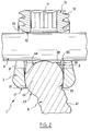
- the retaining means 28 come from the difference in dimension between the internal housing 22 and the U-shaped opening 21, difference forming a rim on which abuts from below the upper edge 83 of the ring 8. This assembly is illustrated in Figures 4 and 5.
- the surgeon places an assembly in the pedicle as described above. Then he sets up the connecting member 6 by inserting it into the “U” opening 21 of the connector 2. Then he sets up the latch 10 between the arms 25 and 26, engaging the thread 12 of the latch 10 with the complementary thread 24 of the connector 2. It implements, by the hexagonal imprint 11, the latch 10, so that the lower face 13 of the latch 10 comes into contact with the connecting member 6 . By continuing to screw the lock 10 between the arms 25 and 26, the surgeon will exert a force by the lock 10 on the connecting member 6, which will push the connecting member 6 until the latter comes to bear on the upper edge 83 of the ring 8.
- the ring 8 then slides along the wall 23 of the internal housing 22 until the face 82 of the ring 8 comes into contact with the surface 43 of the head 42 of the anchoring means 4.
- the surface 43 is itself in contact with the conical section of the wall 23 of the internal housing 22 of the connector 2.
- the clamping force imposed by the surgeon via the lock 10 will allow the ring 8 to slide on the head 42.
- the face 82 will slide on the surface 43, forcing the ring 8 to open by deformation until the face 81 of the ring 8 comes into contact over all or part of its surface with the wall 23 of the internal housing 22 of the connector 2.
- the connecting member 6 comes to bear at a point on the spherical surface 44.
- the head 42 is locked in position, on the one hand by the ring 8 and on the other hand, by the connecting member 6 directly.
- the ring 8 may include at least one slot.
- the slot can be arranged so that the ring forms an unclosed ring.
- the bevel shape due to the wedge shape of the section of the ring may consist of a plurality of sectors separated by slots to form a structure called "umbrella" .
- These various modifications allow easier deformation of the ring 8. This has the consequence of facilitating the introduction of the ring 8 within the internal housing 22 of the connector 2, on the one hand, and, on the other hand, the locking final during use during surgery.
Abstract
Description
L'invention concerne les système d'ostéosynthèse, notamment pour la chirurgie de la colonne vertébrale.The invention relates to osteosynthesis systems, especially for spine surgery.
Le document WO 98/12 976 présente un système d'ostéosynthèse rachidien comprenant un organe d'ancrage de type vis polyaxiale dont le blocage en position s'effectue par appui de la tige de liaison sur une couronne dont la surface inférieure arrondie vient en appui de manière complémentaire sur la tête sphérique de la vis osseuse logée dans le fond d'un logement aménagé dans un connecteur. Un tel système nécessite un effort très important d'appui de la tige sur la couronne pour que la pression surfacique entre la couronne et la tête de vis soit suffisante pour éviter tout mouvement de l'un par rapport à l'autre, mouvement qui aurait pour conséquence de créer une instabilité néfaste à l'ostéosynthèse recherchée.WO 98/12 976 presents a system spinal osteosynthesis comprising an anchoring member polyaxial screw type whose locking in position is carried out by pressing the connecting rod on a crown whose rounded bottom surface comes in additional support on the spherical head of the bone screw housed in the bottom of a fitted accommodation in a connector. Such a system requires effort very important support of the stem on the crown to that the surface pressure between the crown and the head of screws is sufficient to avoid any movement of one in relation to the other, a movement which would have consequence of creating a harmful instability to the osteosynthesis sought.
Un but de l'invention est de fournir un dispositif de blocage en position plus sûr, pour un même effort de serrage.An object of the invention is to provide a device blocking in safer position, for the same effort of Tightening.
Pour cela, on prévoit, selon l'invention, un
ensemble d'ostéosynthèse rachidienne comprenant un
connecteur, des moyens d'ancrage osseux aptes à être
reçus dans le connecteur, un organe de liaison apte à
être reçu dans le connecteur, et une bague apte à venir
en contact avec la tête, l'organe de liaison étant apte
à venir en appui simultanément sur la bague et la tête
lorsque la bague et les moyens d'ancrage sont montés
dans le connecteur.
Ainsi, lors du verrouillage du système
d'ostéosynthèse, l'appui de l'organe de liaison sur la
bague oblige cette dernière à venir appuyer sur les
moyens d'ancrage pour bloquer les moyens d'ancrage en
position au sein du connecteur, et l'appui simultané de
l'organe de liaison sur les moyens d'ancrage vient
renforcer le blocage précédent, ce qui le sécurise tout
en conservant le même effort de serrage pour le
verrouillage.For this, provision is made, according to the invention, for a spinal osteosynthesis assembly comprising a connector, bone anchoring means capable of being received in the connector, a connecting member capable of being received in the connector, and a ring. able to come into contact with the head, the connecting member being able to come to bear simultaneously on the ring and the head when the ring and the anchoring means are mounted in the connector.
Thus, when the osteosynthesis system is locked, pressing the connecting member on the ring forces the latter to come to press on the anchoring means to block the anchoring means in position within the connector, and the simultaneous support of the connecting member on the anchoring means reinforces the previous blocking, which secures it while retaining the same clamping force for locking.
Avantageusement, la bague présente au moins une face conique.Advantageously, the ring has at least one conical face.
Avantageusement, la bague présente une face apte à venir en contact avec les moyens d'ancrage.Advantageously, the ring has a face capable of come into contact with the anchoring means.
Avantageusement, la bague présente une face apte à venir en contact avec une paroi du connecteur.Advantageously, the ring has a face capable of come into contact with a wall of the connector.
Avantageusement, les faces sont coaxiales.Advantageously, the faces are coaxial.
Avantageusement, la bague présente un bord supérieur plan, perpendiculaire à un axe de la bague et apte à venir en contact avec l'organe de liaison.Advantageously, the ring has an edge upper plane, perpendicular to an axis of the ring and able to come into contact with the connecting member.
Avantageusement, la bague présente un bord inférieur plan, perpendiculaire à un axe de la bague.Advantageously, the ring has an edge lower plane, perpendicular to an axis of the ring.
Avantageusement, la bague est apte à s'étendre entre la paroi et les moyens d'ancrage lorsque l'organe de liaison réalise ledit appui.Advantageously, the ring is able to extend between the wall and the anchoring means when the member of connection carries out said support.
Avantageusement, la bague est déformée lorsque l'organe de liaison réalise ledit appui, par référence à une forme de la bague avant montage. Advantageously, the ring is deformed when the liaison body performs said support, with reference to a shape of the ring before mounting.
Avantageusement, la bague présente une épaisseur de
paroi qui varie suivant une hauteur.
Ainsi, la bague présente une section en forme de
coin qui, lors du verrouillage du système, viendra se
coincer simplement entre la paroi du connecteur et les
moyens d'ancrage, ce qui, de manière simple, renforcera
encore plus le blocage en position.Advantageously, the ring has a wall thickness which varies according to a height.
Thus, the ring has a wedge-shaped section which, when the system is locked, will simply get stuck between the wall of the connector and the anchoring means, which, in a simple way, will further reinforce the locking in position.
Avantageusement, la bague comprend une fente.Advantageously, the ring includes a slot.
Avantageusement, la fente est agencée de sorte que la bague forme un anneau non fermé.Advantageously, the slot is arranged so that the ring forms an unclosed ring.
Avantageusement, la bague comprend une pluralité de fentes uniformément réparties sur une circonférence de la bague.Advantageously, the ring comprises a plurality of slots evenly distributed over a circumference of the ring.
Avantageusement, les moyens d'ancrage comprennent une tête présentant une face sensiblement sphérique.Advantageously, the anchoring means comprise a head having a substantially spherical face.
Avantageusement, la tête présente des première et seconde faces sphériques de même centre et de diamètres sensiblement différents.Advantageously, the head has first and second spherical faces with the same center and diameters significantly different.
Avantageusement, les moyens d'ancrage forment une vis polyaxiale.Advantageously, the anchoring means form a polyaxial screw.
Avantageusement, l'ensemble comporte un verrou apte à venir en appui sur l'organe de liaison. Advantageously, the assembly includes a suitable lock to come to bear on the connecting member.
On prévoit aussi, selon l'invention, un système d'ostéosynthèse comprenant un ensemble présentant au moins l'une des caractéristiques précitées.According to the invention, a system is also provided. osteosynthesis comprising a set presenting at minus one of the above characteristics.
D'autres caractéristiques et avantages de l'invention apparaítront lors de la description suivante d'un mode préféré de réalisation. Aux dessins annexés :
- la figure 1 est une vue en perspective du mode préféré de réalisation de l'invention ;
- la figure 2 est une vue en coupe selon le plan II-II du mode de réalisation de la figure 1 ;
- la figure 3 est une vue en perspective de la bague du mode de réalisation préféré ;
- la figure 4 est une vue en perspective du mode de réalisation de la figure 1 avant la mise en place de l'organe de liaison ; et
- la figure 5 est une vue en coupe selon le plan V-V du mode de réalisation de la figure 4.
- Figure 1 is a perspective view of the preferred embodiment of the invention;
- Figure 2 is a sectional view along the plane II-II of the embodiment of Figure 1;
- Figure 3 is a perspective view of the ring of the preferred embodiment;
- Figure 4 is a perspective view of the embodiment of Figure 1 before the establishment of the connecting member; and
- FIG. 5 is a sectional view along the plane VV of the embodiment of FIG. 4.
En référence aux différentes figures 1 à 5, un mode
préféré va être décrit. L'ensemble pour ostéosynthèse de
la colonne vertébrale 1 comprend, ici, un connecteur 2,
un organe de liaison 6 et des moyens d'ancrage 4. Ici,
l'organe de liaison 6 est une tige d'ostéosynthèse et
les moyens d'ancrage 4 sont formés par une vis
pédiculaire. L'ensemble 1 comprend en outre une bague 8
ainsi qu'un verrou 10 apte à verrouiller l'ensemble 1 en
position.With reference to the different figures 1 to 5, a mode
preferred will be described. The assembly for osteosynthesis of
the
Le connecteur 2 comporte une ouverture dite en
« U » 21 formant la partie supérieure du connecteur 2.
Cette ouverture en « U » 21 est délimitée par deux
branches 25 et 26 qui s'étendent de manière sensiblement
parallèle l'une par rapport à l'autre. Les faces
internes des branches 25 et 26 qui s'étendent en regard
l'une de l'autre comportent un filetage 24. D'autre
part, le connecteur 2, dans sa partie inférieure,
comprend un logement interne 22 présentant une paroi 23.
La partie supérieure du logement interne 22 débouche
dans le fond de l'ouverture en « U » 21, et sa partie
inférieure débouche de manière opposée sur une face
inférieure 27 du connecteur 2. Du coté de la face
inférieure 27, la paroi 23 présente une section conique
agencée de manière à ce que l'ouverture au niveau de la
face inférieure 27 soit plus petite que l'ouverture au
niveau du fond de l'ouverture en « U » 21.
Le verrou 10 comprend des moyens de mise en oeuvre
11 qui se présentent ici sous la forme d'un orifice
traversant 11 présentant une empreinte hexagonale. Cette
empreinte hexagonale est apte à recevoir un embout
hexagonal adapté d'un tournevis pour sa mise en oeuvre.
D'autre part, le verrou 10 comprend sur sa paroi
latérale extérieure un filetage 12 complémentaire du
filetage 24 du connecteur 2 entre les branches 25 et 26
duquel il est apte à être reçu.The
Les moyens d'ancrage 4 se présentent ici sous la
forme d'une vis pédiculaire comportant une partie
d'ancrage 41 présentant un filetage osseux, surmontée
d'une tête 42 qui est ici sensiblement sphérique. La
tête 42 présente une première surface sphérique 43 et,
formant le sommet, une seconde surface sphérique 44 dont
le diamètre est inférieur au diamètre de la surface
sphérique 43 mais de même centre que celle-ci. The
On pourra trouver des systèmes d'ostéosynthèse similaires dans le document EP-0 613 664.We can find osteosynthesis systems similar in document EP-0 613 664.
La bague 8 est de forme annulaire et présente une
première face 82 délimitant la paroi interne de la
bague, une seconde face 81 délimitant la paroi externe
de la bague ainsi que des bords supérieur 83 et
inférieur 84 perpendiculaires à l'axe de révolution
géométrique A de la bague 8. Les faces 81 et 82 sont
coaxiales et préférentiellement de forme conique. Leurs
génératrices respectives ne sont pas parallèles entre
elles. Ainsi, les faces sont agencées l'une par rapport
à l'autre de manière à ce que l'épaisseur de la bague 2
au niveau du bord supérieur 83 est supérieure à
l'épaisseur de la bague 8 au niveau du bord inférieur
84. La section de la bague présente ainsi une forme de
coin, donnant une forme en biseau de la bague 8.
Cependant, l'une des génératrices des faces 81 et 82
peut être sensiblement parallèle à l'axe de révolution
A.The
Avant utilisation par un chirurgien, le connecteur
2, les moyens d'ancrage 4 ainsi que la bague 8 sont
montés ensemble. La tête 42 des moyens d'ancrage est
insérée au sein du logement interne 22 du connecteur 2.
Puis, la bague 8 est elle-même insérée au sein du
logement interne 22 du connecteur 2. Ainsi, la tête 42
des moyens d'ancrage 4 se trouve retenue prisonnière au
sein du logement interne 22 à l'encontre de sa sortie
par le haut, du fait de la présence au sein du logement
interne 22 de la bague 8, elle-même retenue prisonnière
comme on le verra plus loin. La tête 42 est retenue à
l'encontre de sa sortie par le bas, du fait de la
présence de la section conique de la paroi 23 du
logement interne 22, qui présente une ouverture au
niveau de la face inférieure 27 du connecteur 2 dont les
dimensions sont inférieures au diamètre de la surface 43
de la tête 42. De plus, la bague 8 est retenue
prisonnière par des moyens de retenue 28 présents au
sein du logement interne 22. Ici, les moyens de retenue
28 viennent de la différence de dimension entre le
logement interne 22 et l'ouverture en U 21, différence
formant un rebord sur lequel vient en butée par le bas
le bord supérieur 83 de la bague 8. Cet assemblage est
illustré aux figures 4 et 5.Before use by a surgeon, the
Lors de l'utilisation au cours d'une opération
chirurgicale, le chirurgien met en place dans le
pédicule un assemblage tel que décrit précédemment. Puis
il met en place l'organe de liaison 6 en l'insérant dans
l'ouverture en « U » 21 du connecteur 2. Puis il met en
place le verrou 10 entre les branches 25 et 26, en
mettant en prise le filetage 12 du verrou 10 avec le
filetage complémentaire 24 du connecteur 2. Il met en
oeuvre, par l'empreinte hexagonale 11, le verrou 10, de
manière à ce que la face inférieure 13 du verrou 10
vienne en contact avec l'organe de liaison 6.
En continuant de visser le verrou 10 entre les
branches 25 et 26, le chirurgien va faire exercer un
effort par le verrou 10 sur l'organe de liaison 6, ce
qui va pousser l'organe de liaison 6 jusqu'à ce que ce
dernier vienne en appui sur le bord supérieure 83 de la
bague 8.
Le verrouillage se poursuivant, la bague 8 glisse
alors le long de la paroi 23 du logement interne 22
jusqu'à ce que la face 82 de la bague 8 vienne en
contact avec la surface 43 de la tête 42 des moyens
d'ancrage 4. La surface 43 est elle-même en contact avec
la section conique de la paroi 23 du logement interne 22
du connecteur 2. Le système se trouve de ce fait dans
une situation telle qu'illustrée à la figure 2.
Lors du verrouillage final qui va permettre le
blocage en position de l'ensemble, l'effort de serrage
imposé par le chirurgien par l'intermédiaire du verrou
10 va permettre de faire glisser la bague 8 sur la tête
42. Pour cela, la face 82 va glisser sur la surface 43,
obligeant la bague 8 à s'ouvrir par déformation jusqu'à
ce que la face 81 de la bague 8 vienne en contact sur
toute ou partie de sa surface avec la paroi 23 du
logement interne 22 du connecteur 2. A ce moment,
l'organe de liaison 6 vient appuyer en un point de la
surface sphérique 44. Ainsi, la tête 42 est bloquée en
position, d'une part par la bague 8 et d'autre part, par
l'organe de liaison 6 directement. On a ainsi un appui
dit trois points, deux points diamétralement opposés au
contact du bord 83 de la bague 8 avec l'organe de
liaison 6 et un point supplémentaire au niveau du
contact de l'organe de liaison 6 avec la surface 44 de
la tête 42 des moyens d'ancrage 4.During use during a surgical operation, the surgeon places an assembly in the pedicle as described above. Then he sets up the connecting
By continuing to screw the
As locking continues, the
During the final locking which will allow the blocking in position of the assembly, the clamping force imposed by the surgeon via the
Bien entendu, on pourra apporter à l'invention de
nombreuses modifications sans sortir du cadre de celle-ci.
Par exemple, la bague 8 pourra comporter au moins
une fente.
La fente pourra être agencée de sorte que la bague
forme un anneau non fermé. Of course, many modifications can be made to the invention without departing from the scope thereof.
For example, the
The slot can be arranged so that the ring forms an unclosed ring.
La forme en biseau due à la forme en coin de la
section de la bague, au lieu d'être continue sur toute
sa circonférence, pourra être constituée d'une pluralité
de secteurs séparés par des fentes pour former une
structure dite « en parapluie ».
Ces différentes modifications permettent une
déformation plus facile de la bague 8. Ceci a pour
conséquence de faciliter l'introduction de la bague 8 au
sein du logement interne 22 du connecteur 2, d'une part,
et, d'autre part, le verrouillage final lors de
l'utilisation en cours d'opération chirurgicale.The bevel shape due to the wedge shape of the section of the ring, instead of being continuous over its entire circumference, may consist of a plurality of sectors separated by slots to form a structure called "umbrella" .
These various modifications allow easier deformation of the
Claims (18)
Applications Claiming Priority (2)
| Application Number | Priority Date | Filing Date | Title |
|---|---|---|---|
| FR0103515A FR2822053B1 (en) | 2001-03-15 | 2001-03-15 | ANCHORING MEMBER WITH SAFETY RING FOR SPINAL OSTEOSYNTHESIS SYSTEM |
| FR0103515 | 2001-03-15 |
Publications (2)
| Publication Number | Publication Date |
|---|---|
| EP1240875A1 true EP1240875A1 (en) | 2002-09-18 |
| EP1240875B1 EP1240875B1 (en) | 2005-10-05 |
Family
ID=8861153
Family Applications (1)
| Application Number | Title | Priority Date | Filing Date |
|---|---|---|---|
| EP02290631A Expired - Lifetime EP1240875B1 (en) | 2001-03-15 | 2002-03-13 | Spinal anchor with locking collar |
Country Status (9)
| Country | Link |
|---|---|
| US (4) | US7686834B2 (en) |
| EP (1) | EP1240875B1 (en) |
| JP (1) | JP4277131B2 (en) |
| KR (1) | KR20020073439A (en) |
| AU (1) | AU782507B2 (en) |
| CA (1) | CA2377028A1 (en) |
| DE (1) | DE60206434T2 (en) |
| ES (1) | ES2246377T3 (en) |
| FR (1) | FR2822053B1 (en) |
Cited By (6)
| Publication number | Priority date | Publication date | Assignee | Title |
|---|---|---|---|---|
| EP1972289A2 (en) | 2007-03-23 | 2008-09-24 | coLigne AG | Elongated stabilization member and bone anchor useful in bone and especially spinal repair processes |
| EP2353428A1 (en) | 2010-02-04 | 2011-08-10 | Promotion Spa | System for attaching a bracelet to a watch case |
| EP2366349A3 (en) * | 2002-10-30 | 2011-10-19 | Zimmer Spine, Inc. | Spinal stabilization system insertion and methods |
| WO2015136203A1 (en) * | 2014-03-12 | 2015-09-17 | Safe Orthopaedics | Osteosynthesis system comprising means for straightening a bone anchoring element relative to a screw head and anchoring screw implemented in such a system |
| US9539012B2 (en) | 2002-10-30 | 2017-01-10 | Zimmer Spine, Inc. | Spinal stabilization systems with quick-connect sleeve assemblies for use in surgical procedures |
| EP2854674B1 (en) | 2012-05-28 | 2017-11-15 | Safe Orthopeadics | Instrument system for carrying out a surgical procedure on the vertebrae comprising temporary immobilization means |
Families Citing this family (132)
| Publication number | Priority date | Publication date | Assignee | Title |
|---|---|---|---|---|
| US7833250B2 (en) | 2004-11-10 | 2010-11-16 | Jackson Roger P | Polyaxial bone screw with helically wound capture connection |
| US6726689B2 (en) | 2002-09-06 | 2004-04-27 | Roger P. Jackson | Helical interlocking mating guide and advancement structure |
| US8377100B2 (en) | 2000-12-08 | 2013-02-19 | Roger P. Jackson | Closure for open-headed medical implant |
| FR2822053B1 (en) * | 2001-03-15 | 2003-06-20 | Stryker Spine Sa | ANCHORING MEMBER WITH SAFETY RING FOR SPINAL OSTEOSYNTHESIS SYSTEM |
| US7862587B2 (en) | 2004-02-27 | 2011-01-04 | Jackson Roger P | Dynamic stabilization assemblies, tool set and method |
| US11224464B2 (en) | 2002-05-09 | 2022-01-18 | Roger P. Jackson | Threaded closure with inwardly-facing tool engaging concave radiused structures and axial through-aperture |
| US8257402B2 (en) | 2002-09-06 | 2012-09-04 | Jackson Roger P | Closure for rod receiving orthopedic implant having left handed thread removal |
| US8876868B2 (en) | 2002-09-06 | 2014-11-04 | Roger P. Jackson | Helical guide and advancement flange with radially loaded lip |
| US8282673B2 (en) | 2002-09-06 | 2012-10-09 | Jackson Roger P | Anti-splay medical implant closure with multi-surface removal aperture |
| US7141051B2 (en) * | 2003-02-05 | 2006-11-28 | Pioneer Laboratories, Inc. | Low profile spinal fixation system |
| US6716214B1 (en) | 2003-06-18 | 2004-04-06 | Roger P. Jackson | Polyaxial bone screw with spline capture connection |
| US8540753B2 (en) | 2003-04-09 | 2013-09-24 | Roger P. Jackson | Polyaxial bone screw with uploaded threaded shank and method of assembly and use |
| US7621918B2 (en) * | 2004-11-23 | 2009-11-24 | Jackson Roger P | Spinal fixation tool set and method |
| US20070016200A1 (en) * | 2003-04-09 | 2007-01-18 | Jackson Roger P | Dynamic stabilization medical implant assemblies and methods |
| US7377923B2 (en) * | 2003-05-22 | 2008-05-27 | Alphatec Spine, Inc. | Variable angle spinal screw assembly |
| US7766915B2 (en) | 2004-02-27 | 2010-08-03 | Jackson Roger P | Dynamic fixation assemblies with inner core and outer coil-like member |
| US8137386B2 (en) | 2003-08-28 | 2012-03-20 | Jackson Roger P | Polyaxial bone screw apparatus |
| US7776067B2 (en) | 2005-05-27 | 2010-08-17 | Jackson Roger P | Polyaxial bone screw with shank articulation pressure insert and method |
| US8366753B2 (en) * | 2003-06-18 | 2013-02-05 | Jackson Roger P | Polyaxial bone screw assembly with fixed retaining structure |
| US8926670B2 (en) | 2003-06-18 | 2015-01-06 | Roger P. Jackson | Polyaxial bone screw assembly |
| US7967850B2 (en) | 2003-06-18 | 2011-06-28 | Jackson Roger P | Polyaxial bone anchor with helical capture connection, insert and dual locking assembly |
| US8814911B2 (en) | 2003-06-18 | 2014-08-26 | Roger P. Jackson | Polyaxial bone screw with cam connection and lock and release insert |
| US8398682B2 (en) | 2003-06-18 | 2013-03-19 | Roger P. Jackson | Polyaxial bone screw assembly |
| FR2856271B1 (en) * | 2003-06-23 | 2005-12-30 | Charles Khalife | SPINAL OSTEOSYNTHESIS PLATE WITH ADAPTABLE HEAD |
| US7087057B2 (en) | 2003-06-27 | 2006-08-08 | Depuy Acromed, Inc. | Polyaxial bone screw |
| FR2859376B1 (en) | 2003-09-04 | 2006-05-19 | Spine Next Sa | SPINAL IMPLANT |
| US7527638B2 (en) | 2003-12-16 | 2009-05-05 | Depuy Spine, Inc. | Methods and devices for minimally invasive spinal fixation element placement |
| US11419642B2 (en) | 2003-12-16 | 2022-08-23 | Medos International Sarl | Percutaneous access devices and bone anchor assemblies |
| US7179261B2 (en) | 2003-12-16 | 2007-02-20 | Depuy Spine, Inc. | Percutaneous access devices and bone anchor assemblies |
| US7160300B2 (en) | 2004-02-27 | 2007-01-09 | Jackson Roger P | Orthopedic implant rod reduction tool set and method |
| US8152810B2 (en) | 2004-11-23 | 2012-04-10 | Jackson Roger P | Spinal fixation tool set and method |
| EP1720468A4 (en) | 2004-02-27 | 2010-01-27 | Roger P Jackson | Orthopedic implant rod reduction tool set and method |
| EP1570794A1 (en) * | 2004-03-04 | 2005-09-07 | U & I Corporation | Bone fixation apparatus, method and tool for assembling the same |
| US7503924B2 (en) | 2004-04-08 | 2009-03-17 | Globus Medical, Inc. | Polyaxial screw |
| US8475495B2 (en) | 2004-04-08 | 2013-07-02 | Globus Medical | Polyaxial screw |
| US7857834B2 (en) * | 2004-06-14 | 2010-12-28 | Zimmer Spine, Inc. | Spinal implant fixation assembly |
| KR100612621B1 (en) * | 2004-07-07 | 2006-08-14 | 주식회사 지에스메디칼 | Pedicle Screw Assembly and Transconnector for Coupling Rods Therein |
| US20060058788A1 (en) | 2004-08-27 | 2006-03-16 | Hammer Michael A | Multi-axial connection system |
| US7651502B2 (en) * | 2004-09-24 | 2010-01-26 | Jackson Roger P | Spinal fixation tool set and method for rod reduction and fastener insertion |
| US8366747B2 (en) * | 2004-10-20 | 2013-02-05 | Zimmer Spine, Inc. | Apparatus for connecting a longitudinal member to a bone portion |
| US8226690B2 (en) | 2005-07-22 | 2012-07-24 | The Board Of Trustees Of The Leland Stanford Junior University | Systems and methods for stabilization of bone structures |
| US8267969B2 (en) | 2004-10-20 | 2012-09-18 | Exactech, Inc. | Screw systems and methods for use in stabilization of bone structures |
| US7604655B2 (en) * | 2004-10-25 | 2009-10-20 | X-Spine Systems, Inc. | Bone fixation system and method for using the same |
| CA2585447A1 (en) | 2004-10-25 | 2006-05-04 | Alphaspine, Inc. | Pedicle screw systems and methods |
| JP2008519656A (en) | 2004-11-10 | 2008-06-12 | ロジャー・ピー・ジャクソン | Helical guide and forward flange with break extension |
| US8926672B2 (en) | 2004-11-10 | 2015-01-06 | Roger P. Jackson | Splay control closure for open bone anchor |
| US9918745B2 (en) | 2009-06-15 | 2018-03-20 | Roger P. Jackson | Polyaxial bone anchor with pop-on shank and winged insert with friction fit compressive collet |
| US8444681B2 (en) | 2009-06-15 | 2013-05-21 | Roger P. Jackson | Polyaxial bone anchor with pop-on shank, friction fit retainer and winged insert |
| WO2006057837A1 (en) * | 2004-11-23 | 2006-06-01 | Jackson Roger P | Spinal fixation tool attachment structure |
| US9168069B2 (en) | 2009-06-15 | 2015-10-27 | Roger P. Jackson | Polyaxial bone anchor with pop-on shank and winged insert with lower skirt for engaging a friction fit retainer |
| US9980753B2 (en) | 2009-06-15 | 2018-05-29 | Roger P Jackson | pivotal anchor with snap-in-place insert having rotation blocking extensions |
| US8308782B2 (en) | 2004-11-23 | 2012-11-13 | Jackson Roger P | Bone anchors with longitudinal connecting member engaging inserts and closures for fixation and optional angulation |
| WO2006058221A2 (en) | 2004-11-24 | 2006-06-01 | Abdou Samy M | Devices and methods for inter-vertebral orthopedic device placement |
| US10076361B2 (en) | 2005-02-22 | 2018-09-18 | Roger P. Jackson | Polyaxial bone screw with spherical capture, compression and alignment and retention structures |
| US8403962B2 (en) | 2005-02-22 | 2013-03-26 | Roger P. Jackson | Polyaxial bone screw assembly |
| US7901437B2 (en) | 2007-01-26 | 2011-03-08 | Jackson Roger P | Dynamic stabilization member with molded connection |
| BRPI0608131A2 (en) * | 2005-03-25 | 2011-05-24 | Blackstone Medical Inc | multi-axial connection system |
| EP2085040B1 (en) | 2005-05-27 | 2012-05-23 | Biedermann Technologies GmbH & Co. KG | Tool for holding or guiding a receiving part for connecting a shank of a bone anchoring element to a rod |
| US8523865B2 (en) * | 2005-07-22 | 2013-09-03 | Exactech, Inc. | Tissue splitter |
| US7717943B2 (en) | 2005-07-29 | 2010-05-18 | X-Spine Systems, Inc. | Capless multiaxial screw and spinal fixation assembly and method |
| WO2007041702A2 (en) | 2005-10-04 | 2007-04-12 | Alphaspine, Inc. | Pedicle screw system with provisional locking aspects |
| US8097025B2 (en) | 2005-10-25 | 2012-01-17 | X-Spine Systems, Inc. | Pedicle screw system configured to receive a straight or curved rod |
| US8100946B2 (en) | 2005-11-21 | 2012-01-24 | Synthes Usa, Llc | Polyaxial bone anchors with increased angulation |
| WO2008008511A2 (en) * | 2006-07-14 | 2008-01-17 | Laszlo Garamszegi | Pedicle screw assembly with inclined surface seat |
| WO2008022268A2 (en) | 2006-08-16 | 2008-02-21 | Pioneer Surgical Technology, Inc. | Spinal rod anchor device and method |
| US8876874B2 (en) * | 2006-08-21 | 2014-11-04 | M. Samy Abdou | Bone screw systems and methods of use |
| US7918857B2 (en) | 2006-09-26 | 2011-04-05 | Depuy Spine, Inc. | Minimally invasive bone anchor extensions |
| US8096996B2 (en) * | 2007-03-20 | 2012-01-17 | Exactech, Inc. | Rod reducer |
| US20090082775A1 (en) * | 2006-10-25 | 2009-03-26 | Moti Altarac | Spondylolisthesis reduction system and method |
| CA2670988C (en) | 2006-12-08 | 2014-03-25 | Roger P. Jackson | Tool system for dynamic spinal implants |
| US7922725B2 (en) | 2007-04-19 | 2011-04-12 | Zimmer Spine, Inc. | Method and associated instrumentation for installation of spinal dynamic stabilization system |
| US8979904B2 (en) | 2007-05-01 | 2015-03-17 | Roger P Jackson | Connecting member with tensioned cord, low profile rigid sleeve and spacer with torsion control |
| US8016832B2 (en) * | 2007-05-02 | 2011-09-13 | Zimmer Spine, Inc. | Installation systems for spinal stabilization system and related methods |
| US8197517B1 (en) | 2007-05-08 | 2012-06-12 | Theken Spine, Llc | Frictional polyaxial screw assembly |
| US20090005815A1 (en) * | 2007-06-28 | 2009-01-01 | Scott Ely | Dynamic stabilization system |
| US9439681B2 (en) * | 2007-07-20 | 2016-09-13 | DePuy Synthes Products, Inc. | Polyaxial bone fixation element |
| US20090069852A1 (en) * | 2007-09-06 | 2009-03-12 | Warsaw Orthopedic, Inc. | Multi-Axial Bone Anchor Assembly |
| US8414588B2 (en) | 2007-10-04 | 2013-04-09 | Depuy Spine, Inc. | Methods and devices for minimally invasive spinal connection element delivery |
| US20090125032A1 (en) * | 2007-11-14 | 2009-05-14 | Gutierrez Robert C | Rod removal instrument |
| US9277940B2 (en) * | 2008-02-05 | 2016-03-08 | Zimmer Spine, Inc. | System and method for insertion of flexible spinal stabilization element |
| EP2442739A1 (en) | 2008-08-01 | 2012-04-25 | Jackson, Roger P. | Longitudinal connecting member with sleeved tensioned cords |
| EP2484300B1 (en) * | 2008-09-05 | 2015-05-20 | Biedermann Technologies GmbH & Co. KG | Stabilization device for bones, in particular for the spinal column |
| PL2337512T3 (en) | 2008-09-12 | 2012-09-28 | Synthes Gmbh | Spinal stabilizing and guiding fixation system |
| US20100087873A1 (en) * | 2008-10-06 | 2010-04-08 | Warsaw Orthopedics, Inc. | Surgical Connectors for Attaching an Elongated Member to a Bone |
| CN102202589A (en) | 2008-11-03 | 2011-09-28 | 斯恩蒂斯有限公司 | Uni-planar bone fixation assembly |
| US11229457B2 (en) | 2009-06-15 | 2022-01-25 | Roger P. Jackson | Pivotal bone anchor assembly with insert tool deployment |
| US9668771B2 (en) | 2009-06-15 | 2017-06-06 | Roger P Jackson | Soft stabilization assemblies with off-set connector |
| US8998959B2 (en) | 2009-06-15 | 2015-04-07 | Roger P Jackson | Polyaxial bone anchors with pop-on shank, fully constrained friction fit retainer and lock and release insert |
| KR20120039622A (en) * | 2009-06-17 | 2012-04-25 | 신세스 게엠바하 | Revision connector for spinal constructs |
| USD746461S1 (en) * | 2009-06-19 | 2015-12-29 | Life Spine, Inc. | Spinal rod connector |
| WO2011017712A2 (en) * | 2009-08-07 | 2011-02-10 | Exatech, Inc. | Systems and methods for stabilization of bone structures, including thorocolumbar stabilization systems and methods |
| AU2010303934B2 (en) | 2009-10-05 | 2014-03-27 | Roger P. Jackson | Polyaxial bone anchor with non-pivotable retainer and pop-on shank, some with friction fit |
| US8764806B2 (en) | 2009-12-07 | 2014-07-01 | Samy Abdou | Devices and methods for minimally invasive spinal stabilization and instrumentation |
| ES2430349T3 (en) * | 2010-03-29 | 2013-11-20 | Biedermann Technologies Gmbh & Co. Kg | Bone anchoring device |
| US9084634B1 (en) | 2010-07-09 | 2015-07-21 | Theken Spine, Llc | Uniplanar screw |
| US10603083B1 (en) | 2010-07-09 | 2020-03-31 | Theken Spine, Llc | Apparatus and method for limiting a range of angular positions of a screw |
| JP2013545527A (en) | 2010-11-02 | 2013-12-26 | ロジャー・ピー・ジャクソン | Multi-axis bone anchor with pop-on shank and pivotable retainer |
| WO2012128825A1 (en) | 2011-03-24 | 2012-09-27 | Jackson Roger P | Polyaxial bone anchor with compound articulation and pop-on shank |
| US8888827B2 (en) | 2011-07-15 | 2014-11-18 | Globus Medical, Inc. | Orthopedic fixation devices and methods of installation thereof |
| US9993269B2 (en) | 2011-07-15 | 2018-06-12 | Globus Medical, Inc. | Orthopedic fixation devices and methods of installation thereof |
| US9186187B2 (en) | 2011-07-15 | 2015-11-17 | Globus Medical, Inc. | Orthopedic fixation devices and methods of installation thereof |
| US9198694B2 (en) | 2011-07-15 | 2015-12-01 | Globus Medical, Inc. | Orthopedic fixation devices and methods of installation thereof |
| US9358047B2 (en) | 2011-07-15 | 2016-06-07 | Globus Medical, Inc. | Orthopedic fixation devices and methods of installation thereof |
| US8845728B1 (en) | 2011-09-23 | 2014-09-30 | Samy Abdou | Spinal fixation devices and methods of use |
| WO2013052626A1 (en) | 2011-10-05 | 2013-04-11 | The Unversity Of Akron | Reduced shock breakaway set screw for use with a surgical construct |
| JP2014533136A (en) | 2011-10-05 | 2014-12-11 | マーク・エイ・ドッドソン | Module retractor and related methods |
| EP2606841B1 (en) | 2011-12-23 | 2016-03-09 | Biedermann Technologies GmbH & Co. KG | Polyaxial bone anchoring device |
| US8911479B2 (en) | 2012-01-10 | 2014-12-16 | Roger P. Jackson | Multi-start closures for open implants |
| US20130226240A1 (en) | 2012-02-22 | 2013-08-29 | Samy Abdou | Spinous process fixation devices and methods of use |
| US9198767B2 (en) | 2012-08-28 | 2015-12-01 | Samy Abdou | Devices and methods for spinal stabilization and instrumentation |
| US9101426B2 (en) | 2012-10-11 | 2015-08-11 | Stryker Trauma Sa | Cable plug |
| US9320617B2 (en) | 2012-10-22 | 2016-04-26 | Cogent Spine, LLC | Devices and methods for spinal stabilization and instrumentation |
| US8911478B2 (en) | 2012-11-21 | 2014-12-16 | Roger P. Jackson | Splay control closure for open bone anchor |
| US10058354B2 (en) | 2013-01-28 | 2018-08-28 | Roger P. Jackson | Pivotal bone anchor assembly with frictional shank head seating surfaces |
| US8852239B2 (en) | 2013-02-15 | 2014-10-07 | Roger P Jackson | Sagittal angle screw with integral shank and receiver |
| US9566092B2 (en) | 2013-10-29 | 2017-02-14 | Roger P. Jackson | Cervical bone anchor with collet retainer and outer locking sleeve |
| US9717533B2 (en) | 2013-12-12 | 2017-08-01 | Roger P. Jackson | Bone anchor closure pivot-splay control flange form guide and advancement structure |
| US9451993B2 (en) | 2014-01-09 | 2016-09-27 | Roger P. Jackson | Bi-radial pop-on cervical bone anchor |
| US9597119B2 (en) | 2014-06-04 | 2017-03-21 | Roger P. Jackson | Polyaxial bone anchor with polymer sleeve |
| US10064658B2 (en) | 2014-06-04 | 2018-09-04 | Roger P. Jackson | Polyaxial bone anchor with insert guides |
| US10499968B2 (en) | 2014-08-08 | 2019-12-10 | Stryker European Holdings I, Llc | Cable plugs for bone plates |
| US11219471B2 (en) | 2014-10-21 | 2022-01-11 | Roger P. Jackson | Pivotal bone anchor receiver having an insert with post-placement tool deployment |
| US10857003B1 (en) | 2015-10-14 | 2020-12-08 | Samy Abdou | Devices and methods for vertebral stabilization |
| US10744000B1 (en) | 2016-10-25 | 2020-08-18 | Samy Abdou | Devices and methods for vertebral bone realignment |
| US10973648B1 (en) | 2016-10-25 | 2021-04-13 | Samy Abdou | Devices and methods for vertebral bone realignment |
| US9763700B1 (en) | 2016-12-14 | 2017-09-19 | Spine Wave, Inc. | Polyaxial bone screw |
| US10610265B1 (en) | 2017-07-31 | 2020-04-07 | K2M, Inc. | Polyaxial bone screw with increased angulation |
| US10507043B1 (en) | 2017-10-11 | 2019-12-17 | Seaspine Orthopedics Corporation | Collet for a polyaxial screw assembly |
| EP3593745A3 (en) | 2018-02-02 | 2020-04-01 | Stryker European Holdings I, LLC | Orthopedic screw and porous structures thereof |
| US11179248B2 (en) | 2018-10-02 | 2021-11-23 | Samy Abdou | Devices and methods for spinal implantation |
| US11439437B1 (en) | 2021-06-09 | 2022-09-13 | Medos International Sarl | Bottom loading bone anchor assemblies with drag retaining ring and related methods |
| US11751915B2 (en) | 2021-07-09 | 2023-09-12 | Roger P. Jackson | Modular spinal fixation system with bottom-loaded universal shank heads |
Citations (6)
| Publication number | Priority date | Publication date | Assignee | Title |
|---|---|---|---|---|
| EP0613664A2 (en) | 1993-02-25 | 1994-09-07 | Howmedica GmbH | A device for setting a spline |
| US5466237A (en) * | 1993-11-19 | 1995-11-14 | Cross Medical Products, Inc. | Variable locking stabilizer anchor seat and screw |
| WO1998012976A1 (en) | 1996-09-24 | 1998-04-02 | Sdgi Holdings, Inc. | Multi-axial bone screw assembly |
| DE29903342U1 (en) * | 1999-02-24 | 1999-06-02 | Grzibek Egbert | Fixing element for holding elements of spinal implants |
| US6053917A (en) * | 1996-09-24 | 2000-04-25 | Sdgi Holdings, Inc. | Multi-axial bone screw assembly |
| WO2001015612A1 (en) * | 1999-09-01 | 2001-03-08 | Sdgi Holdings, Inc. | Multi-axial bone screw assembly |
Family Cites Families (23)
| Publication number | Priority date | Publication date | Assignee | Title |
|---|---|---|---|---|
| US4413512A (en) * | 1982-01-04 | 1983-11-08 | Mobil Oil Corporation | Method of locating potential low water cut hydrocarbon reservoirs |
| US4719423A (en) * | 1985-08-13 | 1988-01-12 | Shell Oil Company | NMR imaging of materials for transport properties |
| US5212447A (en) * | 1990-12-03 | 1993-05-18 | Numar Corporation | Apparatus and technique for nmr diffusion measurement |
| DE4307576C1 (en) | 1993-03-10 | 1994-04-21 | Biedermann Motech Gmbh | Bone screw esp. for spinal column correction - has U=shaped holder section for receiving straight or bent rod |
| MY114398A (en) | 1994-10-20 | 2002-10-31 | Shell Int Research | Nmr logging of natural gas in reservoirs |
| DE19509332C1 (en) | 1995-03-15 | 1996-08-14 | Harms Juergen | Anchoring element |
| US5669911A (en) * | 1995-04-13 | 1997-09-23 | Fastenetix, L.L.C. | Polyaxial pedicle screw |
| US5885286A (en) * | 1996-09-24 | 1999-03-23 | Sdgi Holdings, Inc. | Multi-axial bone screw assembly |
| US5782833A (en) | 1996-12-20 | 1998-07-21 | Haider; Thomas T. | Pedicle screw system for osteosynthesis |
| DE19720782B4 (en) | 1997-05-17 | 2004-12-09 | Synthes Ag Chur, Chur | Device for connecting a side member to a pedicle screw |
| DE29710484U1 (en) * | 1997-06-16 | 1998-10-15 | Howmedica Gmbh | Receiving part for a holding component of a spinal implant |
| US5891145A (en) * | 1997-07-14 | 1999-04-06 | Sdgi Holdings, Inc. | Multi-axial screw |
| US6010503A (en) | 1998-04-03 | 2000-01-04 | Spinal Innovations, Llc | Locking mechanism |
| US6090111A (en) | 1998-06-17 | 2000-07-18 | Surgical Dynamics, Inc. | Device for securing spinal rods |
| US6565565B1 (en) * | 1998-06-17 | 2003-05-20 | Howmedica Osteonics Corp. | Device for securing spinal rods |
| DE19936286C2 (en) * | 1999-08-02 | 2002-01-17 | Lutz Biedermann | bone screw |
| US6331179B1 (en) * | 2000-01-06 | 2001-12-18 | Spinal Concepts, Inc. | System and method for stabilizing the human spine with a bone plate |
| DE10005385A1 (en) * | 2000-02-07 | 2001-08-09 | Ulrich Gmbh & Co Kg | Pedicle screw |
| US6488681B2 (en) * | 2001-01-05 | 2002-12-03 | Stryker Spine S.A. | Pedicle screw assembly |
| CA2434455A1 (en) * | 2001-01-12 | 2002-07-18 | Depuy Acromed, Inc. | Polyaxial screw with improved locking |
| FR2822053B1 (en) * | 2001-03-15 | 2003-06-20 | Stryker Spine Sa | ANCHORING MEMBER WITH SAFETY RING FOR SPINAL OSTEOSYNTHESIS SYSTEM |
| KR100379194B1 (en) * | 2001-10-31 | 2003-04-08 | U & I Co Ltd | Apparatus for fixing bone |
| EP2276007A1 (en) | 2009-07-17 | 2011-01-19 | Nederlandse Organisatie voor toegepast -natuurwetenschappelijk onderzoek TNO | Method and system for remotely guarding an area by means of cameras and microphones. |
-
2001
- 2001-03-15 FR FR0103515A patent/FR2822053B1/en not_active Expired - Lifetime
-
2002
- 2002-03-13 ES ES02290631T patent/ES2246377T3/en not_active Expired - Lifetime
- 2002-03-13 EP EP02290631A patent/EP1240875B1/en not_active Expired - Lifetime
- 2002-03-13 US US10/096,991 patent/US7686834B2/en active Active
- 2002-03-13 DE DE60206434T patent/DE60206434T2/en not_active Expired - Lifetime
- 2002-03-14 AU AU26120/02A patent/AU782507B2/en not_active Ceased
- 2002-03-14 CA CA002377028A patent/CA2377028A1/en not_active Abandoned
- 2002-03-15 KR KR1020020014089A patent/KR20020073439A/en not_active Application Discontinuation
- 2002-03-15 JP JP2002071654A patent/JP4277131B2/en not_active Expired - Lifetime
-
2010
- 2010-02-16 US US12/658,838 patent/US8167916B2/en not_active Expired - Lifetime
-
2012
- 2012-03-26 US US13/429,916 patent/US8845695B2/en not_active Expired - Lifetime
-
2014
- 2014-09-25 US US14/496,640 patent/US9532807B2/en not_active Expired - Lifetime
Patent Citations (6)
| Publication number | Priority date | Publication date | Assignee | Title |
|---|---|---|---|---|
| EP0613664A2 (en) | 1993-02-25 | 1994-09-07 | Howmedica GmbH | A device for setting a spline |
| US5466237A (en) * | 1993-11-19 | 1995-11-14 | Cross Medical Products, Inc. | Variable locking stabilizer anchor seat and screw |
| WO1998012976A1 (en) | 1996-09-24 | 1998-04-02 | Sdgi Holdings, Inc. | Multi-axial bone screw assembly |
| US6053917A (en) * | 1996-09-24 | 2000-04-25 | Sdgi Holdings, Inc. | Multi-axial bone screw assembly |
| DE29903342U1 (en) * | 1999-02-24 | 1999-06-02 | Grzibek Egbert | Fixing element for holding elements of spinal implants |
| WO2001015612A1 (en) * | 1999-09-01 | 2001-03-08 | Sdgi Holdings, Inc. | Multi-axial bone screw assembly |
Cited By (13)
| Publication number | Priority date | Publication date | Assignee | Title |
|---|---|---|---|---|
| EP2366349A3 (en) * | 2002-10-30 | 2011-10-19 | Zimmer Spine, Inc. | Spinal stabilization system insertion and methods |
| US9539012B2 (en) | 2002-10-30 | 2017-01-10 | Zimmer Spine, Inc. | Spinal stabilization systems with quick-connect sleeve assemblies for use in surgical procedures |
| US9603631B2 (en) | 2002-10-30 | 2017-03-28 | Zimmer Spine, Inc. | Spinal stabilization systems and methods |
| US10052137B2 (en) | 2002-10-30 | 2018-08-21 | Zimmer Spine, Inc. | Spinal stabilization systems and methods |
| US10130394B2 (en) | 2002-10-30 | 2018-11-20 | Zimmer Spine, Inc. | Spinal stabilization systems and methods |
| EP1972289A2 (en) | 2007-03-23 | 2008-09-24 | coLigne AG | Elongated stabilization member and bone anchor useful in bone and especially spinal repair processes |
| US10945772B2 (en) | 2007-07-18 | 2021-03-16 | Zimmer Spine, Inc. | Spinal stabilization systems with quick-connect sleeve assemblies for use in surgical procedures |
| US11737794B2 (en) | 2007-07-18 | 2023-08-29 | Zimmer Spine, Inc. | Spinal stabilization systems with quick-connect sleeve assemblies for use in surgical procedures |
| EP2353428A1 (en) | 2010-02-04 | 2011-08-10 | Promotion Spa | System for attaching a bracelet to a watch case |
| EP2854674B1 (en) | 2012-05-28 | 2017-11-15 | Safe Orthopeadics | Instrument system for carrying out a surgical procedure on the vertebrae comprising temporary immobilization means |
| WO2015136203A1 (en) * | 2014-03-12 | 2015-09-17 | Safe Orthopaedics | Osteosynthesis system comprising means for straightening a bone anchoring element relative to a screw head and anchoring screw implemented in such a system |
| US10357286B2 (en) | 2014-03-12 | 2019-07-23 | Safe Orthopaedics | Osteosynthesis system comprising means for straightening a bone anchoring element relative to a screw head and anchoring screw implemented in such a system |
| RU2673964C2 (en) * | 2014-03-12 | 2018-12-03 | Сэйф Ортопаэдикс | Osteosynthesis system comprising means for straightening bone anchoring element relative to screw head and anchoring screw implemented in such system |
Also Published As
| Publication number | Publication date |
|---|---|
| US7686834B2 (en) | 2010-03-30 |
| US8845695B2 (en) | 2014-09-30 |
| US8167916B2 (en) | 2012-05-01 |
| US20150012046A1 (en) | 2015-01-08 |
| US20100152778A1 (en) | 2010-06-17 |
| KR20020073439A (en) | 2002-09-26 |
| US20020133154A1 (en) | 2002-09-19 |
| US9532807B2 (en) | 2017-01-03 |
| AU2612002A (en) | 2002-09-19 |
| AU782507B2 (en) | 2005-08-04 |
| ES2246377T3 (en) | 2006-02-16 |
| JP4277131B2 (en) | 2009-06-10 |
| EP1240875B1 (en) | 2005-10-05 |
| FR2822053A1 (en) | 2002-09-20 |
| DE60206434D1 (en) | 2005-11-10 |
| US20120179206A1 (en) | 2012-07-12 |
| DE60206434T2 (en) | 2006-06-29 |
| FR2822053B1 (en) | 2003-06-20 |
| CA2377028A1 (en) | 2002-09-15 |
| JP2002315756A (en) | 2002-10-29 |
Similar Documents
| Publication | Publication Date | Title |
|---|---|---|
| EP1240875B1 (en) | Spinal anchor with locking collar | |
| EP1339337B1 (en) | Device for fixing a rod and a spherical symmetry screw head | |
| EP0932368B1 (en) | Osteosynthesis system for vertebra arthrodesis | |
| EP1467666B1 (en) | Connector for vertebral anchoring system | |
| CA2393150C (en) | Connecting assembly for spinal osteosynthesis | |
| EP1011504B1 (en) | Apparatus for osteosynthesis comprising a connector of the spinal pin and the anchoring elements | |
| EP1185209B1 (en) | Implant for osteosynthesis device in particular of the backbone | |
| EP1478292A1 (en) | Device for the connection between a shaft and a screw head with spherical symmetry | |
| WO2001006940A1 (en) | Multiaxial connection for osteosynthesis | |
| WO1994023660A1 (en) | Implant for an osteosynthesis device, in particular for the spine | |
| FR2859095A1 (en) | BONE ANCHORING IMPLANT WITH A POLYAXIAL HEAD AND METHOD OF IMPLANTING THE SAME | |
| WO2003024343A1 (en) | Spinal osteosynthesis system comprising a support pad | |
| CA2330802A1 (en) | Backbone osteosynthesis system with clamping means in particular for anterior fixing | |
| FR2925288A1 (en) | Pivotal connecting device for connecting backbone osteosynthesis screw to bone body of vertebra of spinal section to instrument vertebral column, has nut cooperating with element to allow locking of rod in position at interior of screw | |
| WO1999044527A1 (en) | Backbone osteosynthesis system with ligament | |
| FR2845269A1 (en) | Spinal fixation device for immobilizing at least two adjacent vertebrae includes fixing piece in the form of a ring having a central passage through which connecting bar is inserted, and opening through which bone screw element is inserted | |
| FR2747910A1 (en) | ANCHORING ELEMENT FOR ANCHORING INTO A BONE | |
| WO2004047657A2 (en) | Vertebral anchoring device and device for locking same onto a polyaxial screw | |
| EP0814716A1 (en) | Spinal instruments, particularly for a rod | |
| EP0392927A2 (en) | Vertebral implant for osteosynthesis device | |
| FR2732887A1 (en) | Connector for lengthwise and transverse spinal support rods | |
| FR2756334A1 (en) | Fastening device e.g. for hook of vehicle sun visor | |
| EP2008599B1 (en) | Osteosynthesis system using bone plates and screws | |
| FR2787010A1 (en) | Screw fastener for dental implant has cylindrical head of screw fitting inside cylindrical bore of slightly greater diameter than bore surrounding cylindrical top portion | |
| FR2958531A1 (en) | Device for angular indexing of fixation connector of spinal osteosynthesis equipment with respect to spherical head of pedicular screw in bone body of vertebra, has blind housing to completely limit angular displacements of connector |
Legal Events
| Date | Code | Title | Description |
|---|---|---|---|
| PUAI | Public reference made under article 153(3) epc to a published international application that has entered the european phase |
Free format text: ORIGINAL CODE: 0009012 |
|
| AK | Designated contracting states |
Kind code of ref document: A1 Designated state(s): AT BE CH CY DE DK ES FI FR GB GR IE IT LI LU MC NL PT SE TR |
|
| AX | Request for extension of the european patent |
Free format text: AL;LT;LV;MK;RO;SI |
|
| 17P | Request for examination filed |
Effective date: 20030303 |
|
| AKX | Designation fees paid |
Designated state(s): DE ES FR GB IT |
|
| RBV | Designated contracting states (corrected) |
Designated state(s): CH DE ES FR GB IT LI |
|
| 17Q | First examination report despatched |
Effective date: 20030723 |
|
| GRAP | Despatch of communication of intention to grant a patent |
Free format text: ORIGINAL CODE: EPIDOSNIGR1 |
|
| GRAS | Grant fee paid |
Free format text: ORIGINAL CODE: EPIDOSNIGR3 |
|
| GRAA | (expected) grant |
Free format text: ORIGINAL CODE: 0009210 |
|
| AK | Designated contracting states |
Kind code of ref document: B1 Designated state(s): CH DE ES FR GB IT LI |
|
| REG | Reference to a national code |
Ref country code: GB Ref legal event code: FG4D Free format text: NOT ENGLISH |
|
| REG | Reference to a national code |
Ref country code: CH Ref legal event code: EP |
|
| REG | Reference to a national code |
Ref country code: CH Ref legal event code: NV Representative=s name: MICHELI & CIE INGENIEURS-CONSEILS |
|
| REF | Corresponds to: |
Ref document number: 60206434 Country of ref document: DE Date of ref document: 20051110 Kind code of ref document: P |
|
| GBT | Gb: translation of ep patent filed (gb section 77(6)(a)/1977) |
Effective date: 20060119 |
|
| REG | Reference to a national code |
Ref country code: ES Ref legal event code: FG2A Ref document number: 2246377 Country of ref document: ES Kind code of ref document: T3 |
|
| PLBE | No opposition filed within time limit |
Free format text: ORIGINAL CODE: 0009261 |
|
| STAA | Information on the status of an ep patent application or granted ep patent |
Free format text: STATUS: NO OPPOSITION FILED WITHIN TIME LIMIT |
|
| 26N | No opposition filed |
Effective date: 20060706 |
|
| PGFP | Annual fee paid to national office [announced via postgrant information from national office to epo] |
Ref country code: CH Payment date: 20070110 Year of fee payment: 6 |
|
| PGFP | Annual fee paid to national office [announced via postgrant information from national office to epo] |
Ref country code: ES Payment date: 20070326 Year of fee payment: 6 |
|
| PGFP | Annual fee paid to national office [announced via postgrant information from national office to epo] |
Ref country code: IT Payment date: 20070612 Year of fee payment: 6 |
|
| REG | Reference to a national code |
Ref country code: CH Ref legal event code: PL |
|
| PG25 | Lapsed in a contracting state [announced via postgrant information from national office to epo] |
Ref country code: LI Free format text: LAPSE BECAUSE OF NON-PAYMENT OF DUE FEES Effective date: 20080331 Ref country code: CH Free format text: LAPSE BECAUSE OF NON-PAYMENT OF DUE FEES Effective date: 20080331 |
|
| REG | Reference to a national code |
Ref country code: ES Ref legal event code: FD2A Effective date: 20080314 |
|
| PG25 | Lapsed in a contracting state [announced via postgrant information from national office to epo] |
Ref country code: ES Free format text: LAPSE BECAUSE OF NON-PAYMENT OF DUE FEES Effective date: 20080314 |
|
| PG25 | Lapsed in a contracting state [announced via postgrant information from national office to epo] |
Ref country code: IT Free format text: LAPSE BECAUSE OF NON-PAYMENT OF DUE FEES Effective date: 20080313 |
|
| REG | Reference to a national code |
Ref country code: FR Ref legal event code: PLFP Year of fee payment: 15 |
|
| REG | Reference to a national code |
Ref country code: DE Ref legal event code: R081 Ref document number: 60206434 Country of ref document: DE Owner name: STRYKER EUROPEAN OPERATIONS HOLDINGS LLC, KALA, US Free format text: FORMER OWNER: STRYKER EUROPEAN HOLDINGS VI, LLC (N.D. GES. D. STAATES DELAWARE), KALAMAZOO, MICH., US Ref country code: DE Ref legal event code: R081 Ref document number: 60206434 Country of ref document: DE Owner name: STRYKER EUROPEAN OPERATIONS HOLDINGS LLC, KALA, US Free format text: FORMER OWNER: STRYKER SPINE, CESTAS, FR Ref country code: DE Ref legal event code: R082 Ref document number: 60206434 Country of ref document: DE Representative=s name: SAMSON & PARTNER PATENTANWAELTE MBB, DE Ref country code: DE Ref legal event code: R081 Ref document number: 60206434 Country of ref document: DE Owner name: STRYKER EUROPEAN HOLDINGS I, LLC (N.D. GES. D., US Free format text: FORMER OWNER: STRYKER SPINE, CESTAS, FR Ref country code: DE Ref legal event code: R081 Ref document number: 60206434 Country of ref document: DE Owner name: STRYKER EUROPEAN HOLDINGS I, LLC (N.D. GES. D., US Free format text: FORMER OWNER: STRYKER EUROPEAN HOLDINGS VI, LLC (N.D. GES. D. STAATES DELAWARE), KALAMAZOO, MICH., US |
|
| REG | Reference to a national code |
Ref country code: GB Ref legal event code: 732E Free format text: REGISTERED BETWEEN 20161006 AND 20161012 |
|
| REG | Reference to a national code |
Ref country code: GB Ref legal event code: 732E Free format text: REGISTERED BETWEEN 20161013 AND 20161019 |
|
| REG | Reference to a national code |
Ref country code: FR Ref legal event code: TP Owner name: STRYKER EUROPEAN HOLDINGS I, LLC, US Effective date: 20161108 |
|
| REG | Reference to a national code |
Ref country code: FR Ref legal event code: PLFP Year of fee payment: 16 |
|
| REG | Reference to a national code |
Ref country code: FR Ref legal event code: PLFP Year of fee payment: 17 |
|
| REG | Reference to a national code |
Ref country code: DE Ref legal event code: R082 Ref document number: 60206434 Country of ref document: DE Representative=s name: SAMSON & PARTNER PATENTANWAELTE MBB, DE Ref country code: DE Ref legal event code: R081 Ref document number: 60206434 Country of ref document: DE Owner name: STRYKER EUROPEAN OPERATIONS HOLDINGS LLC, KALA, US Free format text: FORMER OWNER: STRYKER EUROPEAN HOLDINGS I, LLC (N.D. GES. D. STAATES DELAWARE), KALAMAZOO, MICH., US |
|
| PGFP | Annual fee paid to national office [announced via postgrant information from national office to epo] |
Ref country code: FR Payment date: 20210210 Year of fee payment: 20 |
|
| REG | Reference to a national code |
Ref country code: GB Ref legal event code: 732E Free format text: REGISTERED BETWEEN 20210408 AND 20210414 |
|
| PGFP | Annual fee paid to national office [announced via postgrant information from national office to epo] |
Ref country code: GB Payment date: 20210308 Year of fee payment: 20 Ref country code: DE Payment date: 20210302 Year of fee payment: 20 |
|
| REG | Reference to a national code |
Ref country code: DE Ref legal event code: R071 Ref document number: 60206434 Country of ref document: DE |
|
| REG | Reference to a national code |
Ref country code: GB Ref legal event code: PE20 Expiry date: 20220312 |
|
| PG25 | Lapsed in a contracting state [announced via postgrant information from national office to epo] |
Ref country code: GB Free format text: LAPSE BECAUSE OF EXPIRATION OF PROTECTION Effective date: 20220312 |