EP1240977A2 - Polishing apparatus - Google Patents
Polishing apparatus Download PDFInfo
- Publication number
- EP1240977A2 EP1240977A2 EP02005388A EP02005388A EP1240977A2 EP 1240977 A2 EP1240977 A2 EP 1240977A2 EP 02005388 A EP02005388 A EP 02005388A EP 02005388 A EP02005388 A EP 02005388A EP 1240977 A2 EP1240977 A2 EP 1240977A2
- Authority
- EP
- European Patent Office
- Prior art keywords
- polishing
- hermetically sealed
- sealed chamber
- substrate
- dresser
- Prior art date
- Legal status (The legal status is an assumption and is not a legal conclusion. Google has not performed a legal analysis and makes no representation as to the accuracy of the status listed.)
- Granted
Links
Images


Classifications
-
- H—ELECTRICITY
- H01—ELECTRIC ELEMENTS
- H01L—SEMICONDUCTOR DEVICES NOT COVERED BY CLASS H10
- H01L21/00—Processes or apparatus adapted for the manufacture or treatment of semiconductor or solid state devices or of parts thereof
- H01L21/02—Manufacture or treatment of semiconductor devices or of parts thereof
- H01L21/04—Manufacture or treatment of semiconductor devices or of parts thereof the devices having at least one potential-jump barrier or surface barrier, e.g. PN junction, depletion layer or carrier concentration layer
- H01L21/18—Manufacture or treatment of semiconductor devices or of parts thereof the devices having at least one potential-jump barrier or surface barrier, e.g. PN junction, depletion layer or carrier concentration layer the devices having semiconductor bodies comprising elements of Group IV of the Periodic System or AIIIBV compounds with or without impurities, e.g. doping materials
- H01L21/30—Treatment of semiconductor bodies using processes or apparatus not provided for in groups H01L21/20 - H01L21/26
- H01L21/302—Treatment of semiconductor bodies using processes or apparatus not provided for in groups H01L21/20 - H01L21/26 to change their surface-physical characteristics or shape, e.g. etching, polishing, cutting
- H01L21/304—Mechanical treatment, e.g. grinding, polishing, cutting
-
- B—PERFORMING OPERATIONS; TRANSPORTING
- B24—GRINDING; POLISHING
- B24B—MACHINES, DEVICES, OR PROCESSES FOR GRINDING OR POLISHING; DRESSING OR CONDITIONING OF ABRADING SURFACES; FEEDING OF GRINDING, POLISHING, OR LAPPING AGENTS
- B24B37/00—Lapping machines or devices; Accessories
- B24B37/27—Work carriers
- B24B37/30—Work carriers for single side lapping of plane surfaces
-
- B—PERFORMING OPERATIONS; TRANSPORTING
- B24—GRINDING; POLISHING
- B24B—MACHINES, DEVICES, OR PROCESSES FOR GRINDING OR POLISHING; DRESSING OR CONDITIONING OF ABRADING SURFACES; FEEDING OF GRINDING, POLISHING, OR LAPPING AGENTS
- B24B47/00—Drives or gearings; Equipment therefor
- B24B47/02—Drives or gearings; Equipment therefor for performing a reciprocating movement of carriages or work- tables
- B24B47/06—Drives or gearings; Equipment therefor for performing a reciprocating movement of carriages or work- tables by liquid or gas pressure only
-
- B—PERFORMING OPERATIONS; TRANSPORTING
- B24—GRINDING; POLISHING
- B24B—MACHINES, DEVICES, OR PROCESSES FOR GRINDING OR POLISHING; DRESSING OR CONDITIONING OF ABRADING SURFACES; FEEDING OF GRINDING, POLISHING, OR LAPPING AGENTS
- B24B49/00—Measuring or gauging equipment for controlling the feed movement of the grinding tool or work; Arrangements of indicating or measuring equipment, e.g. for indicating the start of the grinding operation
- B24B49/16—Measuring or gauging equipment for controlling the feed movement of the grinding tool or work; Arrangements of indicating or measuring equipment, e.g. for indicating the start of the grinding operation taking regard of the load
-
- B—PERFORMING OPERATIONS; TRANSPORTING
- B24—GRINDING; POLISHING
- B24B—MACHINES, DEVICES, OR PROCESSES FOR GRINDING OR POLISHING; DRESSING OR CONDITIONING OF ABRADING SURFACES; FEEDING OF GRINDING, POLISHING, OR LAPPING AGENTS
- B24B53/00—Devices or means for dressing or conditioning abrasive surfaces
- B24B53/017—Devices or means for dressing, cleaning or otherwise conditioning lapping tools
Landscapes
- Engineering & Computer Science (AREA)
- Mechanical Engineering (AREA)
- Physics & Mathematics (AREA)
- Condensed Matter Physics & Semiconductors (AREA)
- General Physics & Mathematics (AREA)
- Manufacturing & Machinery (AREA)
- Computer Hardware Design (AREA)
- Microelectronics & Electronic Packaging (AREA)
- Power Engineering (AREA)
- Finish Polishing, Edge Sharpening, And Grinding By Specific Grinding Devices (AREA)
- Mechanical Treatment Of Semiconductor (AREA)
- Grinding-Machine Dressing And Accessory Apparatuses (AREA)
Abstract
Description
- The present invention relates to a substrate holding apparatus for holding a substrate to be polished and pressing the substrate against a polishing surface, and more particularly to a substrate holding apparatus for holding a substrate such as a semiconductor wafer in a polishing apparatus for polishing the substrate. The present invention also relates to a dressing apparatus for dressing a polishing surface by bringing a dressing member in sliding contact with the polishing surface, and more particularly to a dressing apparatus in the above polishing apparatus.
- In a manufacturing process of a semiconductor device, a thin film is formed on a semiconductor device, and then micromachining processes, such as patterning or forming holes, are performed. Thereafter, the above processes are repeated to form thin films on the semiconductor device. Recently, semiconductor devices have become more integrated, and structure of semiconductor elements has become more complicated. In addition, the number of layers in multilayer interconnections used for a logical system has been increased. Therefore, irregularities on the surface of the semiconductor device are increased, so that the step height on the surface of the semiconductor device becomes larger.
- When the irregularities of the surface of the semiconductor device are increased, the following problems arise. The thickness of a film formed in a portion having a step is relatively small. An open circuit is caused by disconnection of interconnections, or a short circuit is caused by insufficient insulation between the layers. As a result, good products cannot be obtained, and the yield is reduced. Further, even if a semiconductor device initially works normally, reliability of the semiconductor device is lowered after a long-term use. At the time of exposure in a lithography process, if the irradiation surface has irregularities, then a lens unit in an exposure system is locally unfocused. Therefore, if the irregularities of the surface of the semiconductor device are increased, then it is difficult to form a fine pattern on the semiconductor device.
- Thus, in the manufacturing process of a semiconductor device, it is increasingly important to planarize the surface of the semiconductor device. The most important one of the planarizing technologies is chemical mechanical polishing (CMP). In the chemical mechanical polishing using a polishing apparatus, while a polishing liquid containing abrasive particles such as silica (SiO2) therein is supplied onto a polishing surface such as a polishing pad, a substrate such as a semiconductor wafer is brought into sliding contact with the polishing surface, so that the substrate is polished.
- This type of polishing apparatus comprises a polishing table having a polishing surface constituted by a polishing pad (or a fixed abrasive), and a substrate holding apparatus, such as a top ring or a carrier head, for holding a semiconductor wafer. When a semiconductor wafer is polished with this type of polishing apparatus, the semiconductor wafer is held by the substrate holding apparatus and pressed against the polishing table under a predetermined pressure. At this time, the polishing table and the substrate holding apparatus are moved relatively to each other to bring the semiconductor wafer into sliding contact with the polishing surface, so that the surface of the semiconductor wafer is polished to a flat mirror finish.
- When the semiconductor wafer is polished with such a polishing apparatus, a polishing liquid or ground-off particles of the semiconductor material are attached to the polishing surface (polishing pad), resulting in a change in properties of the polishing pad and deterioration in polishing performance. Therefore, if an identical polishing pad is repeatedly used for polishing semiconductor wafers, problems such as lowered polishing rate and uneven polishing are caused. Therefore, a dressing apparatus (dresser) is provided adjacent to the polishing apparatus to regenerate the surface of the polishing pad which has deteriorated due to polishing. In the dressing process, while a dressing member attached to the lower surface of the dresser is pressed against the polishing pad (polishing surface) on the polishing table, the polishing table and the dresser are independently rotated to remove the polishing liquid and the ground-off particles of the semiconductor material which are attached to the polishing surface and to flatten and dress the polishing surface. The dressing member generally comprises a dressing surface on which diamond particles are electrodeposited, and the dressing surface is brought into contact with the polishing surface. This dressing process is also referred to as a conditioning process.
- In the above polishing apparatus, if the relative pressure between the semiconductor wafer which is being polished and the polishing surface of the polishing pad is not uniform over the entire surface of the semiconductor wafer, then the semiconductor wafer may be insufficiently polished or may be excessively polished depending on the pressure applied to the semiconductor wafer. Therefore, it has been attempted to define a hermetically sealed chamber within a substrate holding apparatus with an elastic membrane, and supply a fluid under a predetermined pressure to the hermetically sealed chamber for thereby controlling the pressure imposed on a semiconductor wafer by the substrate holding apparatus.
- In the process of dressing the polishing surface on the polishing table with the dresser, since the polishing surface is scraped by the dressing action, if a dressing load under which the dressing member is pressed against the polishing surface is large, then the service life of the polishing pad (or fixed abrasive) is shortened, and the cost of the polishing apparatus is increased. Therefore, it has also been attempted to define a hermetically sealed chamber within the dresser with an elastic membrane, and supply a fluid under a predetermined pressure to the hermetically sealed chamber for thereby controlling the dressing load.
- However, in the case of the substrate holding apparatus for polishing the semiconductor wafer while controlling the pressure applied to the semiconductor wafer, if a leakage occurs from the hermetically sealed chamber due to a crack or a break in the elastic membrane, then the pressure in the hermetically sealed chamber may not be kept at a preset level, and the semiconductor wafer being polished may be broken.
- Similarly, in the case of the dresser for dressing the polishing surface while controlling the dressing load, if a leakage occurs from the hermetically sealed chamber and the pressure in the hermetically sealed chamber is not kept at a preset level, then the polishing surface may be damaged and the dresser itself may be broken due to an uneven dressing load.
- The present invention has been made in view of the above drawbacks in the conventional technology. It is therefore an object of the present invention to provide a substrate holding apparatus which can safely and accurately control a pressure applied to a substrate, and a dressing apparatus which can safely and accurately control a dressing load applied to a polishing surface.
- Another object of the present invention is to provide a polishing apparatus which has such a substrate holding apparatus or a dressing apparatus.
- In order to achieve the above object, according to a first aspect of the present invention, there is provided a substrate holding apparatus for holding a substrate to be polished and pressing the substrate against a polishing surface, the substrate holding apparatus comprising: a vertically movable top ring body for holding a substrate; a hermetically sealed chamber defined in the top ring body; a fluid supply source for supplying a fluid under a positive pressure or a negative pressure to the hermetically sealed chamber to control the pressure under which the substrate is pressed against the polishing surface; a fluid passage interconnecting the hermetically sealed chamber and the fluid supply source; and a measuring device disposed in the fluid passage for measuring a flow rate in the fluid passage.
- According to a second aspect of the present invention, there is provided a polishing method of polishing a substrate, comprising: pressing a substrate against a polishing surface provided on a polishing table with a top ring; supplying a fluid under a positive pressure or a negative pressure to a hermetically sealed chamber which is defined in the top ring to control the pressure under which the substrate is pressed against the polishing surface; measuring a flow rate of the fluid in a fluid passage through which the fluid flows; and detecting a leakage from the hermetically sealed chamber based on the measured flow rate. In this method, a process of polishing the substrate is preferably stopped when the leakage from the hermetically sealed chamber is detected or the substrate is slipped out of the top ring.
- According to the present invention, by measuring the flow of the pressurized fluid, it is possible to detect a leakage from the hermetically sealed chamber for thereby detecting a break of an elastic membrane which defines the hermetically sealed chamber or an assembling failure of the top ring. Since the pressure in the hermetically sealed chamber can be kept at a preset level, the possibility of the damage to the substrate can be reduced. The measuring device can detect not only a leakage from the hermetically sealed chamber, but also a dislodgment of the substrate from the lower surface of the top ring in the polishing process. Therefore, the possibility of the damage to the substrate can further be reduced.
- According to a third aspect of the present invention, there is provided a dressing apparatus for dressing a polishing surface of a polishing table for polishing a surface of a substrate, the dressing apparatus comprising: a vertically movable dresser body; a dresser plate disposed vertically movably with respect to the dresser body; a dressing member supported by the dresser plate; a hermetically sealed chamber provided between the dresser body and the dresser plate, at least part of the hermetically sealed chamber being defined by an elastic membrane; a fluid supply source for supplying a fluid under a positive pressure or a negative pressure to the hermetically sealed chamber to control a dressing load; a fluid passage interconnecting the hermetically sealed chamber and the fluid supply source; and a measuring device disposed in the fluid passage for measuring a flow rate in the fluid passage.
- According to a fourth aspect of the present invention, there is provided a method of dressing a polishing surface of a polishing table for polishing a surface of a substrate with a dresser, comprising: supplying a fluid under a positive pressure or a negative pressure to a hermetically sealed chamber which is defined in the dresser to control a dressing load; measuring a flow rate of the fluid in a fluid passage through which the fluid flows; and detecting a leakage from the hermetically sealed chamber based on the measured flow rate, In this method, a process of dressing the polishing surface is preferably stopped when the leakage from the hermetically sealed chamber is detected.
- According to the present invention, by measuring the flow of the pressurized fluid, it is possible to detect a leakage from the hermetically sealed chamber for thereby detecting a break of an elastic membrane which defines the hermetically sealed chamber or an assembling failure of the dresser. Since the pressure in the hermetically sealed chamber can be kept at a preset level, the polishing surface is prevented from being damaged by an unbalanced dressing load, and the dresser itself is prevented from being broken.
- According to a preferred aspect of the present invention, the substrate holding apparatus further comprises at least one hermetically sealed chamber defined in the top ring body. Furthermore, the dressing apparatus further comprises at least one hermetically sealed chamber, and at least part of the hermetically sealed chamber is defined by an elastic membrane. In these cases, the substrate holding apparatus or the dressing apparatus further comprises at least one fluid passage so as to correspond to the at least one hermetically sealed chamber, and at least one measuring device disposed in the at least one fluid passage. With this arrangement, it is possible to immediately judge which one of the hermetically sealed chambers in the top ring or the dresser has caused the leakage, and hence the operator can work on only necessary members quickly.
- At least part of the hermetically sealed chamber may be constructed of the substrate. When at least part of the hermetically sealed chamber in the top ring is constructed of the substrate, not only a leakage from the hermetically sealed chamber, but also a dislodgment of the substrate from the top ring can be detected based on the flow rate measured by the measuring device.
- According to a fifth aspect of the present invention, there is provided a polishing apparatus for polishing a substrate, comprising: a polishing table having a polishing surface; and the above substrate holding apparatus. According to a sixth aspect of the present invention, there is provided a polishing apparatus for polishing a substrate, the polishing apparatus comprising: a polishing table having a polishing surface; a substrate holding apparatus for holding a substrate to be polished and pressing the substrate against the polishing surface; and the above dressing apparatus.
- The above and other objects, features, and advantages of the present invention will be apparent from the following description when taken in conjunction with the accompanying drawings which illustrates preferred embodiments of the present invention by way of example.
-
- FIG. 1 is a cross-sectional view showing a whole structure of a polishing apparatus according to a first embodiment of the present invention;
- FIG. 2 is a vertical cross-sectional view showing a top ring in the polishing apparatus shown in FIG. 1;
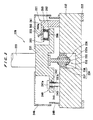
- FIG. 3 is a vertical cross-sectional view showing a dresser in the polishing apparatus shown in FIG. 1, the view showing the state in which the dresser is lifted from a polishing table;
- FIG. 4 is a vertical cross-sectional view of the dresser shown in FIG. 3, the view showing the state in which the dresser is in a dressing operation of a polishing surface;
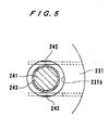
- FIG. 5 is an enlarged cross-sectional view taken along a line V - V of FIG. 4 as turned horizontally at 180°;
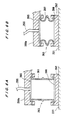
- FIG. 6A is a cross-sectional view of an air bag shown in FIGS. 3 and 4, the view showing the state in which the air bag is inflated; and
- FIG. 6B is a cross-sectional view of the air bag shown in FIGS. 3 and 4, the view showing the state in which the air bag is deflated, i.e., no pressure is applied to the air bag.
-
- A polishing apparatus according to an embodiment of the present invention will be described below with reference to FIGS. 1 through 6B.
- As shown in FIG. 1, the polishing apparatus in the present embodiment comprises a polishing table 100 having a
polishing pad 101 attached thereon, atop ring 1 for holding a substrate to be polished, such as a semiconductor wafer W, and pressing the substrate against thepolishing pad 101, and adresser 220 for dressing the upper surface of thepolishing pad 101. Further, a polishingliquid supply nozzle 102 is disposed above the polishing table 100 for supplying a polishing liquid onto thepolishing pad 101 on the polishing table 100. - Various kinds of polishing pads are available on the market. For example, some of these are SUBA800, IC-1000, and IC-1000/SUBA400 (two-layer cloth) manufactured by Rodel Inc., and Surfin xxx-5 and Surfin 000 manufactured by Fujimi Inc. SUBA800, Surfin xxx-5, and Surfin 000 are nonwoven fabrics bonded by urethane resin, and IC-1000 is made of rigid foam polyurethane (single-layer). Foam polyurethane is porous and has a large number of fine recesses or holes formed in its surface. Non-woven fabrics, such as foam polyurethane or fabrics bonded by urethane resin, are formed in a circular form to constitute a polishing pad.
- Although the polishing surface is constituted by the polishing pad in the present embodiment, the polishing surface is not limited to this polishing pad. For example, the polishing surface may be constituted by a fixed abrasive. The fixed abrasive is formed into a flat plate comprising abrasive particles fixed by a binder. With the fixed abrasive, the polishing process is performed by the abrasive particles which are being self-generated from the fixed abrasive. The fixed abrasive comprises abrasive particles, a binder, and pores. For example, the abrasive particles of CeO2, SiO2, or Al2O3 having an average particle diameter of 0.5 µ m or less are used, and the binder comprising a thermosetting resin such as epoxy resin or phenolic resin, or a thermoplastic resin such as MBS resin or ABS resin is used. Such a fixed abrasive forms a harder polishing surface. The fixed abrasive includes a fixed abrasive pad having a two-layer structure comprising a thin layer of a fixed abrasive and an elastic polishing pad attached to the lower surface of the layer of the fixed abrasive. The above IC-1000 may be used for another hard polishing surface.
- As shown in FIG. 2, the
top ring 1 is connected to a topring drive shaft 11 by auniversal joint 10. As shown in FIG. 1, the topring drive shaft 11 is coupled to a topring air cylinder 111 fixed to atop ring head 110. The topring air cylinder 111 operates to vertically move the topring drive shaft 11 to thus lift and lower thetop ring 1 as a whole. The topring air cylinder 111 also operates to press aretainer ring 3 fixed to the peripheral lower end of atop ring body 2 against thepolishing pad 101 on the polishing table 100. The topring air cylinder 111 is connected to a compressed air source (fluid supply source) 120 via a regulator R1. The regulator R1 regulates the pressure of air supplied to the topring air cylinder 111 for thereby adjusting a pressing force for pressing thepolishing pad 101 with theretainer ring 3. - The top
ring drive shaft 11 is connected to arotary sleeve 112 by a key (not shown). Therotary sleeve 112 has a timingpulley 113 fixedly disposed therearound. Atop ring motor 114 having a drive shaft is fixed to the upper surface of thetop ring head 110. The timingpulley 113 is operatively coupled to a timingpulley 116 mounted on the drive shaft of thetop ring motor 114 by atiming belt 115. When thetop ring motor 114 is energized, the timingpulley 116, thetiming belt 115, and the timingpulley 113 are rotated to rotate therotary sleeve 112 and the topring drive shaft 11 in unison with each other, thus rotating thetop ring 1. - The
top ring head 110 is supported on a topring head shaft 117 which can be positioned. When the topring head shaft 117 is rotated by amotor 118, thetop ring 1 is angularly moved to a pusher (not shown) which serves as a transfer device for transferring a semiconductor wafer W between the polishing table 100 and thetop ring 1. - For polishing the semiconductor wafer W, the semiconductor wafer W is held on the lower surface of the
top ring 1, and pressed against thepolishing pad 101 on the polishing table 100 by thetop ring 1. The polishing table 100 and thetop ring 1 are rotated to move thepolishing pad 101 and the semiconductor wafer W relatively to each other, thus polishing the semiconductor wafer W. At this time, the polishing liquid is supplied from the polishingliquid supply nozzle 102 onto the polishing surface of thepolishing pad 101. For example, a suspension of fine polishing particles of silica (SiO2) or the like in an alkali solution is used as the polishing liquid. Thus, the semiconductor wafer W is polished to a flat mirror finish by the combined effect of a chemical polishing effect attained by the alkali and a mechanical polishing effect attained by the polishing particles. - The
dresser 220 comprises adresser body 221 and a dressingmember 222 fixed to the lower end of thedresser body 221. Thedresser 220 is suspended from adresser head 224 by adresser drive shaft 223, and thedresser drive shaft 223 is coupled to a dresser air cylinder (not shown) fixedly mounted on thedresser head 224. The dresser air cylinder vertically moves thedresser drive shaft 223 to lift or lower thedresser 220 in its entirety and also to move thedresser 220 to a given height from thepolishing pad 101 on the polishing table 100. - The
dresser drive shaft 223 has a rotating mechanism (not shown) which is the same as the rotating mechanism of the topring drive shaft 11 described above. When thedresser drive shaft 223 is rotated, thedresser 220 is rotated in unison therewith. Thedresser head 224 is supported by adresser head shaft 225 which can be positioned. When thedresser head shaft 225 is rotated by amotor 226, thedresser 220 is angularly moved between the polishing table 100 and a standby position. - When the polishing surface of the
polishing pad 101 is clogged with particles in the polishing liquid and ground-off particles of the semiconductor material, a stable polishing performance of thepolishing pad 101 cannot be obtained. Therefore, while the semiconductor wafer W is being polished or between polishing cycles, the dressingmember 222 is pressed against the polishing surface while thedresser body 221 of thedresser 220 is rotated. At this time, a dressing liquid such as pure water is supplied from a dressing liquid supply nozzle (not shown) onto thepolishing pad 101 on the rotating polishing table 100. The polishing surface is thus slightly scraped at a removal rate ranging from 0.01 to 0.3 mm/h, thus preventing the polishing surface from being clogged with particles in the polishing liquid and ground-off particles of the semiconductor material. Thus, the polishing surface is regenerated to keep the polishing surface in a steady state at all times. - The
top ring 1 of the substrate holding apparatus according to the present embodiment of the present invention will be described below. Thetop ring 1 constitutes a substrate holding apparatus according to the present invention. The substrate holding apparatus serves to hold a substrate to be polished, such as a semiconductor wafer, and to press the substrate against a polishing surface on a polishing table. - As shown in FIG. 2, the
top ring 1 comprises thetop ring body 2 in the form of a cylindrical housing with a storage space defined therein, and theretainer ring 3 fixed to the lower end of thetop ring body 2. Thetop ring body 2 is made of a material having high strength and rigidity, such as metal or ceramics. Theretainer ring 3 is made of highly rigid synthetic resin, ceramics, or the like. - The
top ring body 2 comprises acylindrical housing 2a, an annularpressurizing sheet support 2b fitted in thecylindrical housing 2a, and anannular seal 2c fitted over an outer circumferential edge of an upper surface of thecylindrical housing 2a. Theretainer ring 3 is fixed to the lower end of thecylindrical housing 2a and has a lower portion projecting radially inwardly. Theretainer ring 3 may be formed integrally with thetop ring body 2. - The top
ring drive shaft 11 is disposed above the central portion of thecylindrical housing 2a. Thetop ring body 2 is coupled to the topring drive shaft 11 by theuniversal joint 10. Theuniversal joint 10 has a spherical bearing mechanism by which thetop ring body 2 and the topring drive shaft 11 are tiltable with respect to each other, and a rotation transmitting mechanism for transmitting the rotation of the topring drive shaft 11 to thetop ring body 2. The spherical bearing mechanism and the rotation transmitting mechanism transmit a pressing force and a rotating force from the topring drive shaft 11 to thetop ring body 2 while allowing thetop ring body 2 and the topring drive shaft 11 to be tilted with respect to each other. - The spherical bearing mechanism comprises a hemispherical concave recess 11a defined centrally in the lower surface of the top
ring drive shaft 11, a hemisphericalconcave recess 2d defined centrally in the upper surface of thehousing 2a, and a bearingball 12 made of a highly hard material such as ceramics and interposed between the hemisphericalconcave recesses 11a and 2d. The rotation transmitting mechanism comprises drive pins (not shown) fixed to the topring drive shaft 11, and driven pins (not shown) fixed to thehousing 2a. Each of the drive pins is held in engagement with each of the driven pins in such a state that the drive pin and the driven pin are vertically movable relatively to each other. The rotation of the topring drive shaft 11 is transmitted to thetop ring body 2 through the drive and driven pins. Even when thetop ring body 2 is tilted with respect to the topring drive shaft 11, the drive and driven pins remain in engagement with each other while a contact point is displaced, so that the torque of the topring drive shaft 11 can reliably be transmitted to thetop ring body 2. - The
top ring body 2 and theretainer ring 3 secured to thetop ring body 2 jointly have a space defined therein, and within such a space, there are provided aseal ring 42 having a lower end surface which is brought into contact with the peripheral upper surface of the semiconductor wafer W, anannular holder ring 5, and a substantially disk-shapedchucking plate 6 for supporting theseal ring 42. Theseal ring 42 has a radially outer edge clamped between theholder ring 5 and thechucking plate 6 secured to the lower end of theholder ring 5. Theseal ring 42 extends radially inwardly so as to cover the lower surface of thechucking plate 6 near its outer circumferential edge. Theseal ring 42 comprising an elastic membrane is made of a highly strong and durable rubber material such as ethylene propylene rubber (ethylene-propylene terpolymer (EPDM)), polyurethane rubber, or silicone rubber. The semiconductor wafer W has a recess defined in an outer edge thereof, which is referred to as a notch or orientation flat, for recognizing or identifying the orientation of the semiconductor wafer. Therefore, theseal ring 42 should preferably extend radially inwardly from the innermost position of the recess such as a notch or orientation flat. - The chucking
plate 6 may be made of metal. However, when the thickness of a thin film formed on a surface of a semiconductor wafer is measured by a method using eddy current in such a state that the semiconductor wafer to be polished is held by the top ring, the chuckingplate 6 should preferably be made of a non-magnetic material, e.g., an insulating material such as fluororesin or ceramics. - A pressurizing
sheet 7 comprising an elastic membrane extends between theholder ring 5 and thetop ring body 2. The pressurizingsheet 7 has a radially outer edge clamped between thehousing 2a and the pressurizingsheet support 2b, and a radially inner edge clamped between anupper portion 5a and astopper 5b of theholder ring 5. The pressurizingsheet 7 is made of a highly strong and durable rubber material such as ethylene propylene rubber (ethylene-propylene terpolymer (EPDM)), polyurethane rubber, or silicone rubber. - The
top ring body 2, the chuckingplate 6, theholder ring 5, and the pressurizingsheet 7 jointly define a hermetically sealedchamber 21 in thetop ring body 2. As shown in FIG. 2, afluid passage 31 comprising tubes and connectors communicates with the hermetically sealedchamber 21, and thus the hermetically sealedchamber 21 is connected to thecompressed air source 120 via a regulator R2 connected to thefluid passage 31. - In the case where a pressurizing
sheet 7 is made of an elastic material such as rubber, if the pressurizingsheet 7 is clamped between theretainer ring 3 and thetop ring body 2, then the pressurizingsheet 7 is elastically deformed as an elastic material, and a desired horizontal surface cannot be maintained on the lower surface of theretainer ring 3. In order to maintain the desired horizontal surface on the lower surface of theretainer ring 3, the pressurizingsheet 7 is clamped between thehousing 2a of thetop ring body 2 and the pressurizingsheet support 2b provided as a separate member in the present embodiment. Theretainer ring 3 may vertically be movable with respect to thetop ring body 2, or theretainer ring 3 may have a structure capable of pressing the polishing surface independently of thetop ring body 2, as disclosed in Japanese laid-open Patent Publication No. 9-168964 and Japanese Patent Application No. 11-294503 (corresponding to United States Patent Application Serial No. 09/652,148). In such cases, the pressurizingsheet 7 is not necessarily fixed in the aforementioned manner. - Since there is a small gap G between the outer circumferential surface of the
seal ring 42 and the inner circumferential surface of theretainer ring 3, theholder ring 5, the chuckingplate 6, and theseal ring 42 attached to thechucking plate 6 can vertically be moved with respect to thetop ring body 2 and theretainer ring 3, and hence are of a floating structure with respect to thetop ring body 2 and theretainer ring 3. Thestopper 5b of theholder ring 5 has a plurality ofteeth 5c projecting radially outwardly from the outer circumferential edge thereof. When theteeth 5c engage the upper surface of the radially inwardly projecting portion of theretainer ring 3 upon downward movement of theholder ring 5, theholder ring 5 is prevented from causing any further downward movement. - A cleaning
liquid passage 51 in the form of an annular groove is defined in the upper surface of thehousing 2a near its outer circumferential edge over which theseal 2c is fitted. The cleaningliquid passage 51 communicates with afluid passage 32 via a through-hole 52 formed in theseal 2c, and is supplied with a cleaning liquid (pure water) via thefluid passage 32. A plurality of communication holes 53 are defined in thehousing 2a and the pressurizingsheet support 2b in communication with the cleaningliquid passage 51. The communication holes 53 communicate with the small gap G defined between the outer circumferential surface of theseal ring 42 and the inner circumferential surface of theretainer ring 3. Thefluid passage 32 is connected to a cleaning liquid source (not shown) through a rotary joint (not shown). - A
central bag 8 and aring tube 9 which are brought into contact with the semiconductor wafer W are mounted on the lower surface of thechucking plate 6. In the present embodiment, as shown in FIG. 2, thecentral bag 8 having a circular contact surface is disposed centrally on the lower surface of thechucking plate 6, and thering tube 9 having an annular contact surface is disposed radially outwardly of thecentral bag 8 in surrounding relation thereto. Specifically, thecentral bag 8 and thering tube 9 are spaced at predetermined intervals. - The
central bag 8 comprises anelastic membrane 81 which is brought into contact with the upper surface of the semiconductor wafer W, and acentral bag holder 82 for detachably holding theelastic membrane 81 in position. Thecentral bag holder 82 has threadedholes 82a defined therein, and is detachably fastened to the center of the lower surface of thechucking plate 6 byscrews 55 screwed into the threadedholes 82a. Thecentral bag 8 has a hermetically sealedchamber 24 defined therein by theelastic membrane 81 and thecentral bag holder 82. - Similarly, the
ring tube 9 comprises anelastic membrane 91 which is brought into contact with the upper surface of the semiconductor wafer W, and aring tube holder 92 for detachably holding theelastic membrane 91 in position. Thering tube holder 92 has threadedholes 92a defined therein, and is detachably fastened to the lower surface of thechucking plate 6 byscrews 56 screwed into the threadedholes 92a. Thering tube 9 has a hermetically sealedchamber 25 defined therein by theelastic membrane 91 and thering tube holder 92 Theelastic membrane 81 of thecentral bag 8 and theelastic membrane 91 of thering tube 9 are made of a highly strong and durable rubber material such as ethylene propylene rubber (ethylene-propylene terpolymer (EPDM)), polyurethane rubber, or silicone rubber, as with the pressurizingsheet 7. - The semiconductor wafer W to be polished is held by the
top ring 1 in such a state that the semiconductor wafer W is brought into contact with theseal ring 42, theelastic membrane 81 of thecentral bag 8, and theelastic membrane 91 of thering tube 9. Therefore, the semiconductor wafer W, the chuckingplate 6, and theseal ring 42 jointly define a space therebetween. This space is divided into a plurality of spaces by thecentral bag 8 and thering tube 9. Specifically, a hermetically sealedchamber 22 is defined between thecentral bag 8 and thering tube 9, and a hermetically sealedchamber 23 is defined radially outwardly of thering tube 9. -
Fluid passages 33 to 36 comprising tubes and connectors communicate with the hermetically sealedchambers 22 to 25, respectively. The hermetically sealedchambers 22 to 25 are connected to thecompressed air source 120 via respective regulators R3 to R6 connected respectively to thefluid passages 33 to 36. The regulators R3 to R6 connected to thefluid passages 33 to 36 can respectively regulate the pressures of the pressurized fluids supplied to the hermetically sealedchambers 22 to 25. Alternatively, the hermetically sealedchambers 22 to 25 may be connected to a vacuum source. Thus, it is possible to independently control the pressures in the hermetically sealedchambers 22 to 25 or independently introduce atmospheric air or vacuum into the hermetically sealedchambers 22 to 25. Thefluid passages top ring head 110. - As shown in FIG. 1, the
fluid passages chambers 21 to 25 have respective flow meters (measuring device) F1 to F5 connected thereto for measuring the flow rates of the fluid supplied through the fluid passages to the hermetically sealedchambers 21 to 25. If there is a leakage from the hermetically sealedchambers 21 to 25, then a pressurized fluid flows in thefluid passages chambers 21 to 25 have been supplied with the fluids under predetermined pressures. Therefore, by measuring a flow of the pressurized fluid which is caused by a leakage, it is possible to detect the leakage from the hermetically sealed chambers for thereby detecting a break of theelastic membranes top ring 1. Specifically, the flow meters F1 to F5 detect a leakage from the hermetically sealedchambers 21 to 25 based on the measured flow rates, respectively, and perform predetermined processes according to the leakage. Typically, the flow meters F1 to F5 can be arranged to perform a two-stage process. In the first stage, the flow meters F1 to F5 detect a small leakage caused by a small crack in theelastic membrane 81 of thecentral bag 8, theelastic membrane 91 of thering tube 9, or the like and output an alarm signal. In the second stage, the flow meters F1 to F5 detect a greater leakage and output a fault signal. - Operation of the above
top ring 1 will be described in detail below. - When the semiconductor wafer W is to be delivered to the polishing apparatus, the
top ring 1 is moved to a position to which the semiconductor wafer W is transferred. Then, thecentral bag 8 and thering tube 9 are supplied with a fluid under a predetermined pressure to bring the lower end surfaces thereof into intimate contact with the semiconductor wafer W. Thereafter, the hermetically sealedchambers fluid passages chambers chambers top ring 1 is moved to a position above the polishing table 100 having the polishing surface (polishing pad 101) thereon in such a state that the semiconductor wafer W is attracted to thetop ring 1. Theretainer ring 3 holds the outer circumferential edge of the semiconductor wafer W so that the semiconductor wafer W is not removed from thetop ring 1. - For polishing the semiconductor wafer W, the semiconductor wafer W is thus held on the lower surface of the
top ring 1, and the topring air cylinder 111 connected to the topring drive shaft 11 is actuated to press theretainer ring 3 fixed to the lower end of thetop ring 1 against the polishing surface on the polishing table 100 under a predetermined pressure. Then, the pressurized fluids are respectively supplied to the hermetically sealedchambers 22 to 25 under respective pressures, thereby pressing the semiconductor wafer W against the polishing surface on the polishing table 100. The polishingliquid supply nozzle 102 then supplies the polishing liquid onto thepolishing pad 101. Thus, the semiconductor wafer W is polished by thepolishing pad 101 with the polishing liquid being present between the lower surface, being polished, of the semiconductor wafer W and thepolishing pad 101. - The local areas of the semiconductor wafer W that are positioned beneath the hermetically sealed
chambers polishing pad 101 under the respective pressures of the pressurized fluids supplied to the hermetically sealedchambers chamber 24 is pressed through theelastic membrane 81 of thecentral bag 8 against thepolishing pad 101 under the pressure of the pressurized fluid supplied to the hermetically sealedchamber 24. The local area of the semiconductor wafer W that is positioned beneath the hermetically sealedchamber 25 is pressed through theelastic membrane 91 of thering tube 9 against thepolishing pad 101 under the pressure of the pressurized fluid supplied to the hermetically sealedchamber 25. - Therefore, the polishing pressures acting on the respective local areas of the semiconductor wafer W can be adjusted independently by controlling the respective pressures of the pressurized fluids supplied to the hermetically sealed
chambers 22 to 25. The polishing rates depend on the pressing forces applied to areas being polished. The pressing force is a pressure per unit area for pressing the substrate against the polishing surface. Since the pressures applied to the respective areas of the semiconductor wafer W can be controlled, the polishing rates of the respective areas of the semiconductor wafer w can be controlled independently of each other. Therefore, even if the thickness of the thin film to be polished on the surface of the semiconductor wafer W has a radial distribution, the entire surface of the semiconductor wafer W is prevented from being insufficiently polished or excessively polished. - Specifically, even if the thickness of the thin film to be polished on the surface of the semiconductor wafer W differs depending on the radial positions on the semiconductor wafer W, the pressure in a hermetically sealed chamber positioned over a thicker area of the thin film is made higher than the pressure in a hermetically sealed chamber positioned over a thinner area of the thin film, or the pressure in a hermetically sealed chamber positioned over a thinner area of the thin film is made lower than the pressure in a hermetically sealed chamber positioned over a thicker area of the thin film. In this manner, the pressing force applied to the thicker area of the thin film is made higher than the pressing force applied to the thinner area of the thin film, thereby selectively increasing the polishing rate of the thicker area of the thin film. Consequently, the entire surface of the semiconductor wafer W can be polished exactly to a desired level irrespective of the film thickness distribution obtained at the time when the thin film is formed.
- When the semiconductor wafer W is polished, the
seal ring 42 is brought into close contact with the upper surface (reverse side) of the semiconductor wafer W, so that the pressurized fluid supplied to the hermetically sealedchamber 23 is prevented from flowing out to the exterior. For the same reason, even if theelastic membrane 81 of thecentral bag 8 and theelastic membrane 91 of thering tube 9 have through-holes defined in their lower surfaces, pressurized fluids in the hermetically sealedchambers - When the polishing of the semiconductor wafer W is finished, the semiconductor wafer W is attracted under vacuum to the lower surface of the
top ring 1 in the same manner as described above. At this time, the hermetically sealedchamber 21 is vented to the atmosphere or evacuated to develop a negative pressure therein. Then, the entiretop ring 1 is moved to a position to which the semiconductor wafer W is to be transferred, Thereafter, a fluid such as compressed air or a mixture of nitrogen and pure water is ejected to the semiconductor wafer W via thefluid passages top ring 1. If theelastic membrane 81 of thecentral bag 8 and theelastic membrane 91 of thering tube 9 have through-holes defined in their lower surfaces, then downward forces are applied to the semiconductor wafer W by the fluid flowing through these through-holes. Therefore, the semiconductor wafer W can be smoothly released from thetop ring 1. After the semiconductor wafer W is released from thetop ring 1, most of the lower surface of thetop ring 1 is exposed. Therefore, the lower surface of thetop ring 1 can be cleaned relatively easily after the semiconductor wafer W is polished and released. - The polishing liquid used to polish the semiconductor wafer W tends to flow through the gap G between the outer circumferential surface of the
seal ring 42 and the inner circumferential surface of theretainer ring 3. If the polishing liquid is firmly deposited in the gap G, then theholder ring 5, the chuckingplate 6, and theseal ring 42 are prevented from smoothly moving vertically with respect to thetop ring body 2 and theretainer ring 3. To avoid such a drawback, a cleaning liquid (pure water) is supplied through thefluid passage 32 to the cleaningliquid passage 51. Accordingly, the pure water is supplied via the communication holes 53 to a region above the gap G, thus cleaning the members defining the gap G to remove deposits of the polishing liquid. The pure water should preferably be supplied after the polished semiconductor wafer W is released and before a next semiconductor wafer to be polished is attracted to thetop ring 1. It is also preferable to form a plurality of through-holes 3a in theretainer ring 3 so that all the supplied pure water is discharged therethrough out of thetop ring 1 before the next semiconductor wafer is polished, as shown in FIG. 2. Furthermore, if a pressure buildup is developed in aspace 26 defined between theretainer ring 3, theholder ring 5, and the pressurizingsheet 7, then it acts to prevent thechucking plate 6 from being elevated in thetop ring body 2. Therefore, in order to allow thechucking plate 6 to be elevated smoothly in thetop ring body 2, the through-holes 3a should preferably be provided for equalizing the pressure in thespace 26 with the atmospheric pressure. - While the semiconductor wafer W is being polished, the flow meters F1 to F5 measure the flow rates of the fluids supplied via the
fluid passages chambers 21 to 25 to detect a leakage from the hermetically sealedchambers 21 to 25. In the present embodiment, the flow meters F1 to F5 are arranged to perform a two-stage process when a leakage occurs, as described above. - In the two-stage process, an alarm signal is outputted when a small leakage occurs. Since the pressures in the hermetically sealed chambers can be maintained at preset levels regardless of the small leakage, the polishing process is continued even when the small leakage occurs. If a fault signal is outputted, then the polishing process with the
top ring 1 is immediately stopped. Specifically, when a large leakage occurs, the pressures in the hermetically sealed chambers cannot be maintained at preset levels, and also there is a strong possibility of the damage to the semiconductor wafer W. Therefore, the polishing process should be instantaneously stopped. More specifically, the rotation of thetop ring 1 is stopped, thetop ring 1 is elevated, and the rotation of the polishing table 100 is also stopped. In the case where the polishing process is performed at the same time that a dressing process, described later on, is performed, the rotation of thedresser 220 is also stopped, and thedresser 220 is elevated. The polishing process may immediately be stopped in response to the issuance of the alarm signal. - When the polishing process is stopped due to a leakage from one of the hermetically sealed chambers, the elastic membrane which has caused the leakage is replaced or the
top ring 1 is assembled again. In this case, the flow meters F1 to F5 are disposed in the respective fluid passages so as to immediately judge which one of the hermetically sealed chambers in the top ring has caused the leakage, and hence the operator can work on only necessary members quickly. - The hermetically sealed chambers defined in the
top ring 1 include the hermetically sealedchambers elastic membranes fluid passages chambers elastic membranes top ring 1. If the semiconductor wafer W is dislodged from the lower surface of thetop ring 1, then the polishing process should immediately be stopped because there is a strong possibility of the damage to the semiconductor wafer W. In such a case, since the flow meters F2, F3 detect a large leakage, the flow meters F2, F3 issue a fault signal, and hence the polishing apparatus is immediately stopped. - The hermetically sealed
chambers 21 to 25 include the hermetically sealedchambers elastic membranes chambers elastic membranes - The
dresser 220 according to the present embodiment of the present invention will be described below. FIGS. 3 and 4 are vertical cross-sectional views showing thedresser 220 according to the present embodiment of the present invention. FIG. 3 shows a state in which thedresser 220 is lifted from the polishing surface, and FIG. 4 shows a state in which thedresser 220 performs dressing of the polishing surface. - As shown in FIGS. 3 and 4, the
dresser 220 comprises adresser body 221 connected to adresser drive shaft 223, and a dressingmember 222 fixed to thedresser body 221. The dressingmember 222 may comprise a dressing member having diamond particles electrodeposited on its lower surface, a dressing member composed of ceramics such as SiC, or a dressing member composed of another material. The dressingmember 222 may be of an annular shape or a disk shape. - The
dresser body 221 comprises adresser base 231 coupled to thedresser drive shaft 223, a disk-shapeddresser plate 232 which holds the dressingmember 222, agimbal mechanism 233 interconnecting thedresser base 231 and thedresser plate 232 so that thedresser plate 232 is tiltable with respect to thedresser base 231, and arotation transmitting mechanism 240 for transmitting the rotation of thedresser drive shaft 223 to thedresser plate 232. Thedresser base 231 may be coupled to thedresser drive shaft 223 via a separate member. - The
gimbal mechanism 233 is disposed in an upwardlyopen recess 232a defined centrally in an upper portion of thedresser plate 232. Thegimbal mechanism 233 comprises aspherical slide bearing 234, a centeringshaft 235 fixed to thedresser base 231, and alinear bearing 236 inserted between thespherical bearing 234 and the centeringshaft 235. Thespherical bearing 234 comprises a fixedmember 237 fixed to thedresser plate 232 and having a hemispherical concave surface, and a substantially sphericalmovable member 238 slidably fitted in the hemispherical concave surface of the fixedmember 237. Thelinear bearing 236 is inserted and fixedly positioned in the substantially sphericalmovable member 238. The centeringshaft 235 fixed to thedresser base 231 is fitted in thelinear bearing 236. - The centering
shaft 235 is vertically movable with respect to thelinear bearing 236, and the fixedmember 237 are rotatable with respect to thelinear bearing 236 and themovable member 238. Therefore, thespherical bearing 234 allows thedresser plate 232 to be tilted, and thelinear bearing 236 allows thedresser plate 232 to be moved vertically, without causing thedresser plate 232 to be brought out of coaxial alignment with thedresser base 231. - The
rotation transmitting mechanism 240 has a plurality of torque transmitting pins 241 mounted on and fixed to thedresser plate 232 at angularly spaced intervals along a circumferential direction. The torque transmitting pins 241 extend vertically through respective through-holes 231b formed in an outer circumferential flange of thedresser base 231, FIG. 5 is an enlarged cross-sectional view of thedresser 220 shown in FIG. 4, which is a view as viewed from an arrow taken along a line V - V of FIG. 4 and as turned horizontally at 180°. As shown in FIG. 5, two spacedpins 242 are horizontally disposed in thedresser base 231 one on each side of each of thetorque transmitting pin 241 and extend partly through each of the through-hole 231b. Adamper sleeve 243 made of rubber or the like is fitted over thetorque transmitting pin 241. Thetorque transmitting pin 241 and thepins 242 are brought into engagement with each other through thedamper sleeve 243. - When the
dresser drive shaft 223 is rotated about its own axis, thedresser base 231 rotates in unison with thedresser drive shaft 223. The rotation of thedresser base 231 is transmitted to thedresser plate 232 through the engagement between thetorque transmitting pin 241 and thepins 242. During dressing of the polishing surface of the polishing table 100, thedresser plate 232 is tilted so as to follow the inclination of the polishing surface. When thedresser plate 232 is tilted, since thetorque transmitting pin 241 on thedresser plate 232 and thepins 242 on thedresser base 231 are brought into engagement with each other through point contact, thetorque transmitting pin 241 and thepins 242 are held in reliable engagement with each other while varying points of contact, thus allowing the rotational forces of thedresser drive shaft 223 to be transmitted reliably to thedresser plate 232. - The torque transmitting pins 241 have
respective stoppers 241a, mounted on their upper ends, which are larger in size than the inner diameters of the through-holes 231b. When thedresser body 221 is lifted, thestoppers 241a are brought into engagement with the upper surface of thedresser base 231, thus preventing thedresser plate 232 from being dislodged from thedresser base 231. Thedresser base 231 and thedresser plate 232 havecovers dresser body 221, respectively. - The
dresser plate 232 has an L-shapedarm 260 fixedly mounted thereon, and the L-shapedarm 260 has an upper portion projecting upwardly of thedresser base 231. The L-shapedarm 260 has a radiallyinward projection 260a supporting a tubular bellows-shapedresilient membrane 261 on its lower surface and a disk-shapedpressure plate 262 mounted on the lower end of the tubular bellows-shapedresilient membrane 261. Theresilient membrane 261 and thepressure plate 262 jointly constitute an air bag (hermetically sealed chamber) 263. Theair bag 263 and the L-shapedarm 260 should preferably be provided in a plurality of sets spaced at angularly equally spaced intervals along a circumferential direction on thedresser plate 232. In the present embodiment, theair bag 263 and the L-shapedarm 260 are provided in three sets at angularly equally spaced intervals of 120°. The tubular bellows-shapedresilient membrane 261 of theair bag 263 is made of a highly strong and durable rubber material such as ethylene propylene rubber (ethylene-propylene terpolymer (EPDM)), polyurethane rubber, silicone rubber, or the like. Thepressure plate 262 is not fixed to the upper surface of thedresser base 231, but is held in slidable engagement therewith. - A
fluid passage 255 comprising tubes and connectors or the like communicates with theair bag 263. Theair bag 263 is connected to thecompressed air source 120 via a regulator R7 connected to thefluid passage 255. Therefore, the regulator R7 connected to thefluid passage 255 can regulate the pressure of the pressurized fluid supplied to theair bag 263. Alternatively, theair bag 263 may be connected to a vacuum source. Thus, it is possible to control the pressure in theair bag 263 or to introduce atmospheric air or vacuum into theair bag 263. Thefluid passage 255 is connected to the regulator R7 through a rotary joint (not shown) mounted on the upper end of thedresser head 224. - The pressure in the
air bag 263 can be adjusted to any desired pressure ranging from a positive pressure to a negative pressure. When a pressurized fluid such as compressed air is supplied through thefluid passage 255 to theair bag 263, theair bag 263 is inflated, thus applying upward forces to thedresser plate 232. The pressure of the pressurized fluid can be regulated by the regulator R7 to control the dressing load based on a balance between the pressure of the pressurized fluid and the weight of the movable dresser assembly (i.e., thedresser plate 232, the dressingmember 222, the torque transmitting pins 241, thespherical slide bearing 234, thelinear bearing 236, the L-shapedarm 260, and the cover 249). - Specifically, the movable dresser assembly has a total weight of about 12 kg. The dressing load can be controlled in a range of from about 0 N to about 120 N by a balance between the weight of the movable dresser assembly and the positive pressure in the
air bag 263. Because positive pressures can generally be controlled in a wider range and with greater ease than negative pressures, it is preferable to equalize the weight of the movable dresser assembly with a maximum dressing load that is required, and control the dressing load based on the positive pressure in theair bag 263. - As shown in FIG. 1, the
fluid passage 255 connected to theair bag 263 has a flow meter (measuring device) F6 connected thereto for measuring the flow rates of the fluid supplied through the fluid passage to theair bag 263. The flow meter F6 can detect a leakage from theair bag 263 based on the measured flow rate, and perform predetermined processes according to the leakage, as with the flow meters F1 to F5. In the present embodiment, the flow meter F6 is arranged to perform a two-stage process. - FIGS. 6A and 6B show the manner in which the
air bag 263 shown in FIGS. 3 and 4 operates. FIG. 6A shows a state in which theair bag 263 is inflated, and FIG. 6B shows a state in which theair bag 263 is deflated, i.e., no pressure is applied to theair bag 263. In FIG. 6A, the pressurized fluid is introduced into theair bag 263 to inflate theair bag 263, thus expanding theresilient membrane 261 to cause thepressure plate 262 to press thedresser base 231. Accordingly, an upward force is applied to thedresser plate 232. As a result, the dressing load applied to press the polishing surface by the movable dresser assembly is reduced. In FIG. 6B, no pressure is applied to theair bag 263 to deflate theair bag 263, thus contracting theresilient membrane 261. Therefore, thepressure plate 262 does not press thedresser base 231, and no upward force is applied to thedresser plate 232. - In order to accurately control the upward force applied to the
dresser plate 232 with the pressure supplied to theair bag 263, recesses 265 and 266 may be formed respectively in a lower surface of theprojection 260a of the L-shapedarm 260 and an upper surface of thepressure plate 262 for keeping the areas of upper and lower surfaces in theair bag 263 constant even when theresilient membrane 261 is somewhat flexed. - Operation of the
dresser 220 described above will be described in detail below. - A dresser air cylinder (not shown) housed in the
dresser head 224 is actuated to lower thedresser drive shaft 223 together with thedresser body 221 from the position shown in FIG. 3. At this time, thestoppers 241a are held in engagement with the upper surface of thedresser base 231. Thedresser drive shaft 223 is lowered by a predetermined distance to bring the dressingmember 222 into contact with the polishing surface of the polishing table 100. After the dressingmember 222 contacts the polishing surface of the polishing table 100, only thedresser drive shaft 223 and thedresser base 231 are lowered, with the result that thestoppers 241a are disengaged from thedresser base 231. Further, the centeringshaft 235 slides in thelinear bearing 236, and thedresser 220 becomes in such a state shown in FIG. 4. Because thedresser drive shaft 223 is lowered until any flexing of theresilient membrane 261 is removed, the areas of the upper and lower surfaces in theair bag 263 are kept constant by therecesses - With the state as shown in FIG. 4, the
dresser drive shaft 223 is rotated about its own axis, and the dressingmember 222 is brought in sliding contact with the polishing surface, thereby dressing the polishing surface. At this time, the dressing load applied to the polishing surface by the dressingmember 222 is imposed only by thedresser plate 232 and the parts fixed to thedresser plate 232, and hence such dressing load is relatively small. Specifically, in the present embodiment, the dressing load is imposed by thedresser plate 232, the dressingmember 222, the torque transmitting pins 241, thespherical bearing 234, thelinear bearing 236, the L-shapedmember 260, and thecover 249, i.e., the weight of the movable dresser assembly, and hence such dressing load is small. Since the dressing load is small, an amount of material removed from the polishing surface when the polishing surface is dressed can be minimized. - If it is necessary to further reduce the dressing load, then the
air bag 263 is connected to thecompressed air source 120 and the fluid pressure in theair bag 263 is regulated by the regulator R7 to provide a balance between the weight of the movable dresser assembly and the fluid pressure in theair bag 263 for thereby achieving a desired light dressing load. - If the above process is performed in order to apply a dressing load smaller than the weight of the movable dresser assembly, then a dressing load equal to the weight of the movable dresser assembly is temporarily applied to the polishing surface when the dressing
member 222 is brought into contact with the polishing surface. In order to avoid this drawback, thedresser 220 should preferably be operated as follows: - With the state as shown in FIG. 3, the
air bag 263 is connected to the fluid supply source and inflated to bring thedresser plate 232 to its uppermost position. Then, the dresser air cylinder housed in thedresser head 224 is actuated to lower thedresser drive shaft 223 and thedresser body 221 by a predetermined distance. At this time, a slight clearance is present between the lower surface of the dressingmember 222 and the polishing surface. Thereafter, the fluid pressure in theair bag 263 is adjusted to a certain pressure by the regulator R7 to further lower thedresser plate 232 until the lower surface of the dressingmember 222 contacts the polishing surface, as shown in FIG. 4. Thus, the dressing load applied to the polishing surface is of a desired level. Since the lowering distance of the movable dresser assembly is small, theresilient membrane 261 is almost free from any flexing, and the pressure-bearing areas of the upper and lower surfaces in theair bag 263 are kept constant by therecesses air bag 263 before thedresser drive shaft 223 is lowered may be of such a level as to achieve a desired dressing load. - While the polishing surface is being dressed, the flow meter F6 measures the flow rate of the fluid supplied via the
fluid passage 255 to theair bag 263 to detect a leakage from theair bag 263. In the present embodiment, the flow meter F6 is arranged to perform a two-stage process when a leakage occurs, as described above. An alarm signal is outputted when a small leakage occurs, as in the case of the flow meters F1 to F5. The dressing process is continued even when the small leakage occurs. If a fault signal is outputted, then the dressing process with thedresser 220 is immediately stopped. Thedresser 220 has a plurality ofair bags 263, and FIGS. 3 and 4 show one of theair bags 263. If the pressure in any one of theair bags 263 is not maintained at preset levels, then a dressing load is not balanced to damage the polishing surface. In the worst case, thedresser 220 itself may be broken. Specifically, the rotation of thedresser 220 is stopped, thedresser 220 is elevated, and the rotation of the polishing table 100 is also stopped. If the dressing process is performed at the same time that a polishing process is performed, then the rotation of thetop ring 1 is also stopped, and thetop ring 1 is elevated. The dressing process may immediately be stopped in response to the issuance of an alarm signal. - When the dressing process is stopped due to a leakage from one of the
air bags 263, theelastic membrane 261 which has caused the leakage is replaced or thedresser 220 is assembled again. In this case, the flow meters are disposed in the respective fluid passages connected to a plurality ofair bags 263 so as to immediately judge which one of theair bags 263 in thedresser 220 has caused the leakage, and hence the operator can work on only necessary members quickly. In FIG. 1, only one fluid passage connected to one of theair bags 263 is shown, and the other passages and flow meters are not shown. - A leakage from the hermetically sealed
chambers 21 to 25 in thetop ring 1 and a leakage from theair bags 263 in thedresser 220 may be detected by not only the flow meters but also pressure gages. Since the pressures in the hermetically sealedchambers 21 to 25 and theair bags 263 are maintained at constant levels by the regulators R2 to R7, flow meters should preferably be used to detect a small leakage or detect a leakage instantaneously. - For example, the layout and structure of the hermetically sealed chambers in the
top ring 1 and the layout and structure of the air bag in thedresser 220 are not limited to the illustrated details, but may be modified as needed. While the polishing apparatus having a plurality of hermetically sealed chambers in thetop ring 1 and a plurality of air bags in thedresser 220 has been described above, the polishing apparatus may have at least one hermetically sealed chamber and at least one air bag. The present invention is applicable to a top ring for holding the entire surface of a semiconductor wafer with one elastic membrane to polish the semiconductor wafer. In this case, if at least part of the hermetically sealed chamber is constructed of the semiconductor wafer, then it is possible to detect when the semiconductor wafer is slipped out of the top ring. For example, if at least one hole is defined in a surface of the elastic membrane which is brought into contact with the semiconductor wafer, it is possible to detect when the semiconductor wafer is slipped out of the top ring. - In the above embodiment, the flow meters detect a leakage in the two-stage process. However, the flow meters may detect a leakage in a single stage or three or more stages. A signal representative of such a detected leakage may be used as an alarm signal or a fault signal for the operation of the polishing apparatus.
- Although certain preferred embodiments of the present invention have been shown and described in detail, it should be understood that various changes and modifications may be made therein without departing from the scope of the appended claims.
- According to its broadest aspect, the invention relates to a substrate holding apparatus comprising:
- a ring for holding a substrate;
- a hermetically sealed chamber;
- a fluid source; and
- a fluid passage interconnecting said hermetically sealed chamber and said fluid supply source.
-
- It should be noted that objects and advantages of the invention may be attained by means of compatible combination(s) particularly pointed out in the items of the following summary of the invention.
-
- 1. A substrate holding apparatus for holding a
substrate to be polished and pressing said substrate against
a polishing surface, said substrate holding apparatus
comprising:
- a top ring body for holding a substrate;
- a hermetically sealed chamber defined in said top ring body;
- a fluid supply source for supplying a fluid under a positive pressure or a negative pressure to said hermetically sealed chamber to control the pressure under which said substrate is pressed against said polishing surface;
- a fluid passage interconnecting said hermetically sealed chamber and said fluid supply source; and
- a measuring device disposed in said fluid passage for measuring a flow rate in said fluid passage.
- 2. A substrate holding apparatus
, further comprising at least one hermetically sealed chamber in said top ring body. - 3. A substrate holding apparatus
, further comprising at least one fluid passage so as to correspond to said at least one hermetically sealed chamber, and at least one measuring device disposed in said at least one fluid passage. - 4. A substrate holding apparatus
wherein at least part of said hermetically sealed chamber is constructed of said substrate. - 5. A polishing apparatus for polishing a
substrate, comprising:
- a polishing table having a polishing surface; and
- a substrate holding apparatus for holding a
substrate to be polished and pressing said substrate against
said polishing surface, said substrate holding apparatus
comprising:
- a top ring body for holding a substrate;
- a hermetically sealed chamber defined in said top ring body;
- a fluid supply source for supplying a fluid under a positive pressure or a negative pressure to said hermetically sealed chamber to control the pressure under which said substrate is pressed against said polishing surface;
- a fluid passage interconnecting said hermetically sealed chamber and said fluid supply source; and
- a measuring device disposed in said fluid passage for measuring a flow rate in said fluid passage.
- 6. A polishing apparatus
further comprising at least one hermetically sealed chamber in said top ring body. - 7. A polishing apparatus
further comprising at least one fluid passage so as to correspond to said at least one hermetically sealed chamber, and at least one measuring device disposed in said at least one fluid passage. - 8. A polishing apparatus
wherein at least part of said hermetically sealed chamber is constructed of said substrate. - 9. A polishing method of polishing a substrate,
comprising:
- pressing a substrate against a polishing surface provided on a polishing table with a top ring;
- supplying a fluid under a positive pressure or a negative pressure to a hermetically sealed chamber which is defined in said top ring to control the pressure under which said substrate is pressed against said polishing surface; and
- measuring a flow rate of said fluid in a fluid passage through which said fluid flows.
- 10. A polishing method
further comprising detecting a leakage from said hermetically sealed chamber based on the measured flow rate. - 11. A polishing method
wherein a process of polishing said substrate is stopped when the leakage from said hermetically sealed chamber is detected. - 12. A polishing method
wherein a dislodgment of the substrate from said top ring is detected based on the measured flow rate. - 13. A dressing apparatus for dressing a polishing
surface of a polishing table for polishing a surface of a
substrate, said dressing apparatus comprising:
- a dresser body;
- a dresser plate disposed vertically movably with respect to said dresser body;
- a dressing member supported by said dresser plate;
- a hermetically sealed chamber provided between said dresser body and said dresser plate, at least part of said hermetically sealed chamber being defined by an elastic membrane;
- a fluid supply source for supplying a fluid under a positive pressure or a negative pressure to said hermetically sealed chamber to control a dressing load;
- a fluid passage interconnecting said hermetically sealed chamber and said fluid supply source; and
- a measuring device disposed in said fluid passage for measuring a flow rate in said fluid passage.
- 14. A dressing apparatus
further comprising at least one hermetically sealed chamber, at least part of said hermetically sealed chamber being defined by an elastic membrane. - 15. A dressing apparatus
further comprising at least one fluid passage so as to correspond to said at least one hermetically sealed chamber, and at least one measuring device disposed in said at least one fluid passage. - 16. A polishing apparatus for polishing a
substrate, said polishing apparatus comprising:
- a polishing table having a polishing surface;
- a substrate holding apparatus for holding a substrate to be polished and pressing said substrate against said polishing surface; and
- a dressing apparatus for dressing said polishing
surface, said dressing apparatus comprising:
- a dresser body;
- a dresser plate disposed vertically movably with respect to said dresser body;
- a dressing member supported by said dresser plate;
- a hermetically sealed chamber provided between said dresser body and said dresser plate, at least part of said hermetically sealed chamber being defined by an elastic membrane;
- a fluid supply source for supplying a fluid under a positive pressure or a negative pressure to said hermetically sealed chamber to control a dressing load;
- a fluid passage interconnecting said hermetically sealed chamber and said fluid supply source; and
- a measuring device disposed in said fluid passage for measuring a flow rate in said fluid passage.
- 17. A polishing apparatus
further comprising at least one hermetically sealed chamber, at least part of said hermetically sealed chamber being defined by an elastic membrane. - 18. A polishing apparatus
further comprising at least one fluid passage so as to correspond to said at least one hermetically sealed chamber, and at least one measuring device disposed in said at least one fluid passage. - 19. A method of dressing a polishing surface of a
polishing table for polishing a surface of a substrate with
a dresser, comprising:
- supplying a fluid under a positive pressure or a negative pressure to a hermetically sealed chamber which is defined in said dresser to control a dressing load; and
- measuring a flow rate of said fluid in a fluid passage through which said fluid flows.
- 20. A method further comprising detecting a leakage from said hermetically sealed Chamber based on the measured flow rate.
- 21. A method wherein a process of dressing said polishing surface is stopped when the leakage from said hermetically sealed chamber is detected.
-
Claims (17)
- A substrate holding apparatus for holding a substrate to be polished and pressing said substrate against a polishing surface, said substrate holding apparatus comprising:a top ring body for holding a substrate;a hermetically sealed chamber defined in said top ring body;a fluid supply source for supplying a fluid under a positive pressure or a negative pressure to said hermetically sealed chamber to control the pressure under which said substrate is pressed against said polishing surface;a fluid passage interconnecting said hermetically sealed chamber and said fluid supply source; anda measuring device disposed in said fluid passage for measuring a flow rate in said fluid passage.
- A polishing apparatus for polishing a substrate, comprising:a polishing table having a polishing surface; anda substrate holding apparatus for holding a substrate to be polished and pressing said substrate against said polishing surface, said substrate holding apparatus comprising:a top ring body for holding a substrate;a hermetically sealed chamber defined in said top ring body;a fluid supply source for supplying a fluid under a positive pressure or a negative pressure to said hermetically sealed chamber to control the pressure under which said substrate is pressed against said polishing surface;a fluid passage interconnecting said hermetically sealed chamber and said fluid supply source; anda measuring device disposed in said fluid passage for measuring a flow rate in said fluid passage.
- An apparatus according to claim 1 or 2, further comprising at least one hermetically sealed chamber in said top ring body.
- An apparatus according to claim 3 further comprising at least one fluid passage so as to correspond to said at least one hermetically sealed chamber, and at least one measuring device disposed in said at least one fluid passage.
- A polishing apparatus according to claim 4 wherein at least part of said hermetically sealed chamber is constructed of said substrate.
- A polishing method of polishing a substrate, comprising:pressing a substrate against a polishing surface provided on a polishing table with a top ring;supplying a fluid under a positive pressure or a negative pressure to a hermetically sealed chamber which is defined in said top ring to control the pressure under which said substrate is pressed against said polishing surface; andmeasuring a flow rate of said fluid in a fluid passage through which said fluid flows.
- A polishing method according to claim 6 further comprising detecting a leakage from said hermetically sealed chamber based on the measured flow rate.
- A polishing method according to claim 7 wherein a process of polishing said substrate is stopped when the leakage from said hermetically sealed chamber is detected.
- A polishing method according to claim 6 , wherein a dislodgment of the substrate from said top ring is detected based on the measured flow rate.
- A dressing apparatus for dressing a polishing surface of a polishing table for polishing a surface of a substrate, said dressing apparatus comprising:a dresser body;a dresser plate disposed vertically movably with respect to said dresser body;a dressing member supported by said dresser plate;a hermetically sealed chamber provided between said dresser body and said dresser plate, at least part of said hermetically sealed chamber being defined by an elastic membrane;a fluid supply source for supplying a fluid under a positive pressure or a negative pressure to said hermetically sealed chamber to control a dressing load;a fluid passage interconnecting said hermetically sealed chamber and said fluid supply source; anda measuring device disposed in said fluid passage for measuring a flow rate in said fluid passage.
- A polishing apparatus for polishing a substrate, said polishing apparatus comprising:a polishing table having a polishing surface;a substrate holding apparatus for holding a substrate to be polished and pressing said substrate against said polishing surface; anda dressing apparatus for dressing said polishing surface, said dressing apparatus comprising:a dresser body;a dresser plate disposed vertically movably with respect to said dresser body;a dressing member supported by said dresser plate;a hermetically sealed chamber provided between said dresser body and said dresser plate, at least part of said hermetically sealed chamber being defined by an elastic membrane;a fluid supply source for supplying a fluid under a positive pressure or a negative pressure to said hermetically sealed chamber to control a dressing load;a fluid passage interconnecting said hermetically sealed chamber and said fluid supply source; anda measuring device disposed in said fluid passage for measuring a flow rate in said fluid passage.
- A polishing method according to claim 10 or 11 further comprising at least one hermetically sealed chamber, at least part of said hermetically sealed chamber being defined by an elastic membrane.
- A polishing apparatus according to claim 12, further comprising at least one fluid passage so as to correspond to said at least one hermetically sealed chamber, and at least one measuring device disposed in said at least one fluid passage.
- A method of dressing a polishing surface of a polishing table for polishing a surface of a substrate with a dresser, comprising:supplying a fluid under a positive pressure or a negative pressure to a hermetically sealed chamber which is defined in said dresser to control a dressing load; andmeasuring a flow rate of said fluid in a fluid passage through which said fluid flows.
- A method according to claim 14, further comprising detecting a leakage from said hermetically sealed chamber based on the measured flow rate.
- A method according to claim 15, wherein a process of dressing said polishing surface is stopped when the leakage from said hermetically sealed chamber is detected.
- A substrate holding apparatus comprising:a ring for holding a substrate;a hermetically sealed chamber;a fluid source; anda fluid passage interconnecting said hermetically sealed chamber and said fluid supply source.
Applications Claiming Priority (2)
| Application Number | Priority Date | Filing Date | Title |
|---|---|---|---|
| JP2001077133A JP3922887B2 (en) | 2001-03-16 | 2001-03-16 | Dresser and polishing device |
| JP2001077133 | 2001-03-16 |
Publications (3)
| Publication Number | Publication Date |
|---|---|
| EP1240977A2 true EP1240977A2 (en) | 2002-09-18 |
| EP1240977A3 EP1240977A3 (en) | 2003-11-12 |
| EP1240977B1 EP1240977B1 (en) | 2010-09-01 |
Family
ID=18933937
Family Applications (1)
| Application Number | Title | Priority Date | Filing Date |
|---|---|---|---|
| EP02005388A Expired - Lifetime EP1240977B1 (en) | 2001-03-16 | 2002-03-15 | Polishing apparatus |
Country Status (5)
| Country | Link |
|---|---|
| US (3) | US6957998B2 (en) |
| EP (1) | EP1240977B1 (en) |
| JP (1) | JP3922887B2 (en) |
| KR (1) | KR100870941B1 (en) |
| DE (1) | DE60237485D1 (en) |
Cited By (4)
| Publication number | Priority date | Publication date | Assignee | Title |
|---|---|---|---|---|
| WO2004105112A1 (en) | 2003-05-20 | 2004-12-02 | Ebara Corporation | Substrate holding apparatus and polishing apparatus |
| WO2005046935A1 (en) * | 2003-11-12 | 2005-05-26 | Dow Global Technologies Inc. | Materials and methods for low pressure chemical-mechanical planarization |
| EP1568074A1 (en) * | 2001-06-07 | 2005-08-31 | Doosan DND Co., Ltd. | Carrier head for chemical mechanical polishing apparatus |
| EP3932615A1 (en) * | 2020-06-29 | 2022-01-05 | Ebara Corporation | Substrate processing apparatus, substrate processing method, and storage medium that stores program to cause computer in substrate processing apparatus to execute substrate processing method |
Families Citing this family (43)
| Publication number | Priority date | Publication date | Assignee | Title |
|---|---|---|---|---|
| US7101799B2 (en) | 2001-06-19 | 2006-09-05 | Applied Materials, Inc. | Feedforward and feedback control for conditioning of chemical mechanical polishing pad |
| KR100688712B1 (en) * | 2002-09-17 | 2007-02-28 | 동부일렉트로닉스 주식회사 | Apparatus for confirming part of gas leakage of a polishing housing |
| JP4448297B2 (en) * | 2002-12-27 | 2010-04-07 | 株式会社荏原製作所 | Substrate polishing apparatus and substrate polishing method |
| US6945845B2 (en) * | 2003-03-04 | 2005-09-20 | Applied Materials, Inc. | Chemical mechanical polishing apparatus with non-conductive elements |
| JP2004342751A (en) * | 2003-05-14 | 2004-12-02 | Toshiba Corp | Cmp slurry, polishing method, and method of manufacturing semiconductor device |
| JP2005034959A (en) * | 2003-07-16 | 2005-02-10 | Ebara Corp | Polishing device and retainer ring |
| US7445697B2 (en) * | 2003-10-22 | 2008-11-04 | Nexx Systems, Inc. | Method and apparatus for fluid processing a workpiece |
| US7727366B2 (en) | 2003-10-22 | 2010-06-01 | Nexx Systems, Inc. | Balancing pressure to improve a fluid seal |
| US20050283993A1 (en) * | 2004-06-18 | 2005-12-29 | Qunwei Wu | Method and apparatus for fluid processing and drying a workpiece |
| JP2006090453A (en) * | 2004-09-24 | 2006-04-06 | Tokiko Techno Kk | Gas supply device |
| JP4453019B2 (en) * | 2005-03-25 | 2010-04-21 | 富士フイルム株式会社 | Rubbing method, optical film manufacturing method and apparatus |
| JP4814677B2 (en) * | 2006-03-31 | 2011-11-16 | 株式会社荏原製作所 | Substrate holding device and polishing device |
| EP2024136A2 (en) * | 2006-05-02 | 2009-02-18 | Nxp B.V. | Wafer de-chucking |
| US7402098B2 (en) * | 2006-10-27 | 2008-07-22 | Novellus Systems, Inc. | Carrier head for workpiece planarization/polishing |
| US7335092B1 (en) * | 2006-10-27 | 2008-02-26 | Novellus Systems, Inc. | Carrier head for workpiece planarization/polishing |
| TWI367524B (en) * | 2007-08-01 | 2012-07-01 | Univ Nat Taiwan Science Tech | Chemical mechanical polishing apparatus and chemical mechanical polishing method thereof |
| JP5144191B2 (en) * | 2007-09-21 | 2013-02-13 | 株式会社ディスコ | Chuck table mechanism of grinding equipment |
| JP4658182B2 (en) * | 2007-11-28 | 2011-03-23 | 株式会社荏原製作所 | Polishing pad profile measurement method |
| JP2010036284A (en) * | 2008-08-01 | 2010-02-18 | Tokyo Seimitsu Co Ltd | Polishing head having no contamination of metal |
| KR101057228B1 (en) * | 2008-10-21 | 2011-08-16 | 주식회사 엘지실트론 | Pressurized head of mirror polishing device |
| DE102008061267A1 (en) * | 2008-12-10 | 2010-06-24 | Schneider Gmbh & Co. Kg | Polishing device with rotary feedthrough |
| JP5236515B2 (en) * | 2009-01-28 | 2013-07-17 | 株式会社荏原製作所 | Dressing apparatus, chemical mechanical polishing apparatus and method |
| KR101022277B1 (en) * | 2009-02-25 | 2011-03-21 | 그린스펙(주) | Carrier head structure for polishing apparatus of silicon bare wafers |
| CN102205522B (en) * | 2011-05-24 | 2013-01-30 | 清华大学 | Gas path positive pressure system used for chemico-mechanical polishing and chemico-mechanical polishing equipment |
| WO2013134075A1 (en) | 2012-03-08 | 2013-09-12 | Applied Materials, Inc. | Detecting membrane breakage in a carrier head |
| JP5789634B2 (en) | 2012-05-14 | 2015-10-07 | 株式会社荏原製作所 | Polishing pad for polishing a workpiece, chemical mechanical polishing apparatus, and method for polishing a workpiece using the chemical mechanical polishing apparatus |
| KR101579591B1 (en) * | 2014-06-19 | 2015-12-23 | 주식회사 알앤비 | Specimen pressure cylinder for polishing head |
| KR102173323B1 (en) | 2014-06-23 | 2020-11-04 | 삼성전자주식회사 | Carrier head, chemical mechanical polishing apparatus and wafer polishing method |
| JP6535529B2 (en) * | 2015-07-08 | 2019-06-26 | 不二越機械工業株式会社 | Dressing apparatus and dressing method for polishing cloth of double-side polishing apparatus |
| JP6353418B2 (en) * | 2015-08-18 | 2018-07-04 | 株式会社荏原製作所 | Substrate adsorption method, top ring and substrate polishing apparatus |
| SG10201606197XA (en) | 2015-08-18 | 2017-03-30 | Ebara Corp | Substrate adsorption method, substrate holding apparatus, substrate polishing apparatus, elastic film, substrate adsorption determination method for substrate holding apparatus, and pressure control method for substrate holding apparatus |
| JP6721967B2 (en) * | 2015-11-17 | 2020-07-15 | 株式会社荏原製作所 | Buff processing device and substrate processing device |
| JP6713377B2 (en) * | 2016-08-10 | 2020-06-24 | エイブリック株式会社 | Polishing head, CMP polishing apparatus having polishing head, and method for manufacturing semiconductor integrated circuit device using the same |
| CN106425861B (en) * | 2016-12-06 | 2018-08-31 | 重庆市江津区前进焊接材料厂 | A kind of control system of the hand-held polishing machine of pressure stability |
| JP6927560B2 (en) * | 2017-01-10 | 2021-09-01 | 不二越機械工業株式会社 | Work polishing head |
| JP6757696B2 (en) * | 2017-04-21 | 2020-09-23 | 株式会社荏原製作所 | A computer-readable recording medium that records a leak inspection method and a program for executing this leak inspection method. |
| KR102652046B1 (en) * | 2018-10-01 | 2024-03-29 | 주식회사 케이씨텍 | Conditioner of chemical mechanical polishing apparatus |
| JP7058209B2 (en) * | 2018-11-21 | 2022-04-21 | 株式会社荏原製作所 | How to hold the board in the board holder |
| CN109664188B (en) * | 2018-12-14 | 2020-05-22 | 北京半导体专用设备研究所(中国电子科技集团公司第四十五研究所) | Wafer loading and unloading device |
| KR20200127328A (en) | 2019-05-02 | 2020-11-11 | 삼성전자주식회사 | Conditioner, chemical mechanical polishing apparatus including the same and method of manufacturing a semiconductor device using the apparatus |
| US11325223B2 (en) * | 2019-08-23 | 2022-05-10 | Applied Materials, Inc. | Carrier head with segmented substrate chuck |
| JP7436684B2 (en) * | 2020-06-26 | 2024-02-22 | アプライド マテリアルズ インコーポレイテッド | deformable substrate chuck |
| KR20220026624A (en) * | 2020-08-25 | 2022-03-07 | 주식회사 제우스 | Wafer processing apparatus and controlling method thereof |
Citations (4)
| Publication number | Priority date | Publication date | Assignee | Title |
|---|---|---|---|---|
| JPH10230450A (en) * | 1997-02-19 | 1998-09-02 | Ebara Corp | Polishing device and method |
| US5913714A (en) * | 1997-04-04 | 1999-06-22 | Ontrak Systems, Inc. | Method for dressing a polishing pad during polishing of a semiconductor wafer |
| US6019670A (en) * | 1997-03-10 | 2000-02-01 | Applied Materials, Inc. | Method and apparatus for conditioning a polishing pad in a chemical mechanical polishing system |
| US6135858A (en) * | 1997-07-03 | 2000-10-24 | Canon Kabushiki Kaisha | Substrate holding device and polishing method and polishing apparatus using the same |
Family Cites Families (6)
| Publication number | Priority date | Publication date | Assignee | Title |
|---|---|---|---|---|
| US5762539A (en) * | 1996-02-27 | 1998-06-09 | Ebara Corporation | Apparatus for and method for polishing workpiece |
| US5851140A (en) * | 1997-02-13 | 1998-12-22 | Integrated Process Equipment Corp. | Semiconductor wafer polishing apparatus with a flexible carrier plate |
| US5957751A (en) * | 1997-05-23 | 1999-09-28 | Applied Materials, Inc. | Carrier head with a substrate detection mechanism for a chemical mechanical polishing system |
| US6217429B1 (en) * | 1999-07-09 | 2001-04-17 | Applied Materials, Inc. | Polishing pad conditioner |
| JP2002144218A (en) * | 2000-11-09 | 2002-05-21 | Ebara Corp | Polishing device |
| JP4072810B2 (en) * | 2001-01-19 | 2008-04-09 | 株式会社荏原製作所 | Dressing apparatus and polishing apparatus provided with the dressing apparatus |
-
2001
- 2001-03-16 JP JP2001077133A patent/JP3922887B2/en not_active Expired - Fee Related
-
2002
- 2002-03-15 EP EP02005388A patent/EP1240977B1/en not_active Expired - Lifetime
- 2002-03-15 US US10/097,568 patent/US6957998B2/en not_active Expired - Lifetime
- 2002-03-15 DE DE60237485T patent/DE60237485D1/en not_active Expired - Lifetime
- 2002-03-15 KR KR1020020014104A patent/KR100870941B1/en active IP Right Grant
-
2005
- 2005-07-29 US US11/191,962 patent/US7108581B2/en not_active Expired - Lifetime
-
2006
- 2006-08-07 US US11/499,784 patent/US7458879B2/en not_active Expired - Fee Related
Patent Citations (4)
| Publication number | Priority date | Publication date | Assignee | Title |
|---|---|---|---|---|
| JPH10230450A (en) * | 1997-02-19 | 1998-09-02 | Ebara Corp | Polishing device and method |
| US6019670A (en) * | 1997-03-10 | 2000-02-01 | Applied Materials, Inc. | Method and apparatus for conditioning a polishing pad in a chemical mechanical polishing system |
| US5913714A (en) * | 1997-04-04 | 1999-06-22 | Ontrak Systems, Inc. | Method for dressing a polishing pad during polishing of a semiconductor wafer |
| US6135858A (en) * | 1997-07-03 | 2000-10-24 | Canon Kabushiki Kaisha | Substrate holding device and polishing method and polishing apparatus using the same |
Non-Patent Citations (1)
| Title |
|---|
| PATENT ABSTRACTS OF JAPAN vol. 1998, no. 14, 31 December 1998 (1998-12-31) & JP 10 230450 A (EBARA CORP), 2 September 1998 (1998-09-02) * |
Cited By (10)
| Publication number | Priority date | Publication date | Assignee | Title |
|---|---|---|---|---|
| EP1568074A1 (en) * | 2001-06-07 | 2005-08-31 | Doosan DND Co., Ltd. | Carrier head for chemical mechanical polishing apparatus |
| EP1568074A4 (en) * | 2001-06-07 | 2007-01-03 | Doosan Dnd Co Ltd | Carrier head for chemical mechanical polishing apparatus |
| WO2004105112A1 (en) | 2003-05-20 | 2004-12-02 | Ebara Corporation | Substrate holding apparatus and polishing apparatus |
| EP1625613A1 (en) * | 2003-05-20 | 2006-02-15 | Ebara Corporation | Substrate holding apparatus and polishing apparatus |
| CN100377311C (en) * | 2003-05-20 | 2008-03-26 | 株式会社荏原制作所 | Substrate holding apparatus and polishing apparatus |
| EP1625613A4 (en) * | 2003-05-20 | 2008-07-16 | Ebara Corp | Substrate holding apparatus and polishing apparatus |
| US7465214B2 (en) | 2003-05-20 | 2008-12-16 | Ebara Corporation | Substrate holding apparatus and polishing apparatus |
| WO2005046935A1 (en) * | 2003-11-12 | 2005-05-26 | Dow Global Technologies Inc. | Materials and methods for low pressure chemical-mechanical planarization |
| EP3932615A1 (en) * | 2020-06-29 | 2022-01-05 | Ebara Corporation | Substrate processing apparatus, substrate processing method, and storage medium that stores program to cause computer in substrate processing apparatus to execute substrate processing method |
| US11911868B2 (en) | 2020-06-29 | 2024-02-27 | Ebara Corporation | Substrate processing apparatus, substrate processing method, and storage medium that stores program to cause computer in substrate processing apparatus to execute substrate processing method |
Also Published As
| Publication number | Publication date |
|---|---|
| EP1240977B1 (en) | 2010-09-01 |
| DE60237485D1 (en) | 2010-10-14 |
| JP2002280337A (en) | 2002-09-27 |
| JP3922887B2 (en) | 2007-05-30 |
| US6957998B2 (en) | 2005-10-25 |
| KR100870941B1 (en) | 2008-12-01 |
| US7458879B2 (en) | 2008-12-02 |
| KR20020073440A (en) | 2002-09-26 |
| US20060270323A1 (en) | 2006-11-30 |
| US20020132559A1 (en) | 2002-09-19 |
| US7108581B2 (en) | 2006-09-19 |
| US20050260925A1 (en) | 2005-11-24 |
| EP1240977A3 (en) | 2003-11-12 |
Similar Documents
| Publication | Publication Date | Title |
|---|---|---|
| EP1240977B1 (en) | Polishing apparatus | |
| US7357699B2 (en) | Substrate holding apparatus and polishing apparatus | |
| US7850509B2 (en) | Substrate holding apparatus | |
| US7632173B2 (en) | Substrate holding apparatus and polishing apparatus | |
| US6926585B2 (en) | Pressure control system and polishing apparatus | |
| US7465214B2 (en) | Substrate holding apparatus and polishing apparatus | |
| US7108592B2 (en) | Substrate holding apparatus and polishing apparatus | |
| US6899604B2 (en) | Dressing apparatus and polishing apparatus | |
| US20060128286A1 (en) | Polishing apparatus | |
| US20050054272A1 (en) | Polishing method |
Legal Events
| Date | Code | Title | Description |
|---|---|---|---|
| PUAI | Public reference made under article 153(3) epc to a published international application that has entered the european phase |
Free format text: ORIGINAL CODE: 0009012 |
|
| AK | Designated contracting states |
Kind code of ref document: A2 Designated state(s): AT BE CH CY DE DK ES FI FR GB GR IE IT LI LU MC NL PT SE TR |
|
| AX | Request for extension of the european patent |
Free format text: AL;LT;LV;MK;RO;SI |
|
| PUAL | Search report despatched |
Free format text: ORIGINAL CODE: 0009013 |
|
| AK | Designated contracting states |
Kind code of ref document: A3 Designated state(s): AT BE CH CY DE DK ES FI FR GB GR IE IT LI LU MC NL PT SE TR |
|
| AX | Request for extension of the european patent |
Extension state: AL LT LV MK RO SI |
|
| RIC1 | Information provided on ipc code assigned before grant |
Ipc: 7B 24B 49/16 B Ipc: 7B 24B 53/007 B Ipc: 7B 24B 37/04 A |
|
| 17P | Request for examination filed |
Effective date: 20040428 |
|
| AKX | Designation fees paid |
Designated state(s): DE FR |
|
| 17Q | First examination report despatched |
Effective date: 20040628 |
|
| 17Q | First examination report despatched |
Effective date: 20040628 |
|
| GRAP | Despatch of communication of intention to grant a patent |
Free format text: ORIGINAL CODE: EPIDOSNIGR1 |
|
| GRAS | Grant fee paid |
Free format text: ORIGINAL CODE: EPIDOSNIGR3 |
|
| GRAA | (expected) grant |
Free format text: ORIGINAL CODE: 0009210 |
|
| AK | Designated contracting states |
Kind code of ref document: B1 Designated state(s): DE FR |
|
| REF | Corresponds to: |
Ref document number: 60237485 Country of ref document: DE Date of ref document: 20101014 Kind code of ref document: P |
|
| PLBE | No opposition filed within time limit |
Free format text: ORIGINAL CODE: 0009261 |
|
| STAA | Information on the status of an ep patent application or granted ep patent |
Free format text: STATUS: NO OPPOSITION FILED WITHIN TIME LIMIT |
|
| 26N | No opposition filed |
Effective date: 20110606 |
|
| REG | Reference to a national code |
Ref country code: DE Ref legal event code: R097 Ref document number: 60237485 Country of ref document: DE Effective date: 20110606 |
|
| REG | Reference to a national code |
Ref country code: FR Ref legal event code: ST Effective date: 20111130 |
|
| PG25 | Lapsed in a contracting state [announced via postgrant information from national office to epo] |
Ref country code: FR Free format text: LAPSE BECAUSE OF NON-PAYMENT OF DUE FEES Effective date: 20110331 |
|
| PGFP | Annual fee paid to national office [announced via postgrant information from national office to epo] |
Ref country code: DE Payment date: 20190305 Year of fee payment: 18 |
|
| REG | Reference to a national code |
Ref country code: DE Ref legal event code: R119 Ref document number: 60237485 Country of ref document: DE |
|
| PG25 | Lapsed in a contracting state [announced via postgrant information from national office to epo] |
Ref country code: DE Free format text: LAPSE BECAUSE OF NON-PAYMENT OF DUE FEES Effective date: 20201001 |