This invention relates to an entrance management
apparatus and entrance management method which manage
entrance (or entry) into a room or important facility
in which much importance is given to the security, for
example.
Conventionally, a system which controls the
open/closed state of a door or the fastened/unfastened
state of a lock mounted on a door based on
authentication of a subject person by using information
of a living body such as a face inherent to a person is
provided. For example, in Jpn. Pat. Appln. KOKAI
Publication No. 7-175929, an automatic door
opening/closing management system which manages
entrance (or entry) into a room or important facility
in which much importance is given to the security is
proposed. In Jpn. Pat. Appln. KOKAI Publication
No. 7-175929, the feature of a body (face) of a person
is identified according to image data and the
locked/unlocked state of the door is controlled based
on the result of identification.
However, the automatic door opening/closing
management system disclosed in Jpn. Pat. Appln. KOKAI
Publication No. 7-175929 has the following problems.
There is no description about the management of
entrance of a visitor who is not previously registered
or the management of entrance of a plurality of
visitors. For example, in the authentication process
based on a face image, the precision of the
authentication process is lowered and the degree of
security is lowered as the number of registered persons
to be authenticated increases.
Further, there is no description about a change of
the physical feature of a registered person with time
or the management of entrance of a temporary user.
In addition, there is no description about
a process for confirming or monitoring the result of
authentication based on the physical feature in order
to enhance the security.
Accordingly, an object of this invention is to
provide an entrance management apparatus and entrance
management method which can attain a high degree of
security and permit a visitor to easily enter.
An entrance management apparatus according to one
embodiment of this invention which manages entrance
through a first gate and entrance through a second gate
provided inside the first gate comprises a first living
body information input section which acquires living
body information of the visitor at the first gate, a
feature amount extracting section which extracts a
feature amount of the living body information of the
visitor based on the living body information acquired
by the first living body information input section, a
registration section which registers the feature amount
of the living body information extracted by the feature
amount extracting section in correspondence to entrance
permission time information which defines time during
which the visitor whose living body information is
acquired by the first living body information input
section is permitted to enter through the second gate,
a second living body information input section which
acquires living body information of the visitor at the
second gate, a collating section which extracts a
feature amount of the living body information of
the visitor based on the living body information
acquired by the second living body information input
section and collates the extracted feature amount with
the feature amount registered in the registration
section, and an entrance control section which controls
the entrance of the visitor whose living body
information is acquired by the second living body
information input section through the second gate based
on the result of collation by the collating section and
the entrance permission time information registered in
the registration section and corresponding to the
result of collation.
An entrance management apparatus according to
another embodiment of this invention which manages
entrance through a gate comprises an image input
section which acquires a face image of a visitor at the
gate, a face detecting section which detects a feature
amount of the face based on the face image acquired by
the image input section, an image recording section
which records the face image acquired by the image
input section in the case where the feature amount of
the face is detected by the face detecting section, and
an access control section which permits access through
the gate only in the case where the feature amount of
the face is detected by the face detecting section.
An entrance management method according to still
another embodiment of this invention which is a method
for managing entrance through a first gate and entrance
through a second gate provided inside the first gate
comprises acquiring living body information of
a visitor at the first gate, extracting a feature
amount of the living body information of the visitor
based on the living body information acquired at the
first gate, registering the extracted feature amount of
the living body information in correspondence to
entrance permission time information which defines time
during which the visitor is permitted to enter through
the second gate into a registration section, acquiring
living body information of the visitor at the second
gate, extracting a feature amount of the living body
information of the visitor based on the living body
information acquired at the second gate and collating
the extracted feature amount with the feature amount
registered in the registration section, and controlling
the entrance of the visitor whose living body
information is acquired at the second gate through
the second gate based on the result of collation and
the entrance permission time information registered in
the registration section and corresponding to the
result of collation.
An entrance management apparatus according to a
further embodiment of this invention which manages
entrance through a first gate and entrance through a
plurality of second gates provided inside the first
gate comprises a registration section in which a
feature amount of living body information of at least
one person who has authorization of entrance through
the first gate is registered in correspondence to the
presence or absence of authorization of entrance
through at least one of the second gates, a destination
input section by use of which a destination is input by
a visitor at the first gate, a first living body
information input section which acquires living body
information of the visitor at the first gate, a first
feature amount extracting section which extracts a
feature amount of living body information based on the
living body information acquired by the first living
body information input section, a first collating
section which collates the feature amount extracted by
the first feature amount extracting section with the
feature amount registered in the registration section,
a first entrance control section which permits entrance
of the visitor in the case where the feature amount is
successfully collated with the feature amount
registered in the registration section by the first
collating section and controls entrance of the visitor
based on a specification of a person who exists in the
destination input by the destination input section in
the case where the feature amount is not successfully
collated with the feature amount registered in the
registration section by the first collating section, a
storage section which stores a feature amount of living
body information of a visitor who obtains permission of
entrance based on the specification of the person
existing in the destination in correspondence to one of
the second gates which corresponds to the destination,
a second living body information input section which
acquires living body information of the visitor at the
second gate, a second feature amount extracting section
which extracts a feature amount of living body
information based on the living body information
acquired by the second living body information input
section, a second collating section which collates the
feature amount extracted by the second feature amount
extracting section with the feature amount registered
in the registration section and the feature amount
stored in the storage section, a second entrance
control section which permits entrance through the
second gate in the case where the feature amount is
successfully collated with the face feature amount
corresponding to a person who has authorization to
enter through the second gate and registered in the
registration section by the second collating section
and controls entrance of the visitor through the second
gate based on a specification of a person who exists
inside the second gate in the case where the feature
amount is successfully collated with the feature amount
of living body information corresponding to a person
who has no authorization to enter through the second
gate and registered in the registration section by the
second collating section or in the case where
the feature amount is successfully collated with the
feature amount of living body information of a person
related to the second gate which is the destination
stored in the storage section, and an access inhibiting
section which inhibits access through any one of the
second gates by the visitor in the case where the
feature amount is not successfully collated with the
feature amount registered in the registration section
by the second collating section or in the case where
the feature amount is not successfully collated with
the feature amount of living body information of a
person related to the second gate which is the
destination stored in the storage section.
An entrance management method according to another
embodiment of this invention which is a method for
managing entrance through a first gate and entrance
through a plurality of second gates provided inside the
first gate comprises registering a feature amount of
living body information of at least one person who has
authorization of entrance through the first gate in
correspondence to the presence or absence of
authorization of entrance through at least one of the
second gates into a registration section, inputting a
destination by a visitor at the first gate, acquiring
living body information of a visitor at the first gate,
extracting a feature amount of living body information
based on the acquired living body information,
collating the extracted feature amount with the feature
amount registered in the registration section,
permitting entrance of the visitor in the case where
the feature amount is successfully collated with the
feature amount registered in the registration section
and controlling entrance of the visitor based on
a specification of a person who exists in the
destination in the case where the feature amount is not
successfully collated with the feature amount
registered in the registration section, storing
a feature amount of living body information of the
visitor who obtains permission of entrance based on the
specification of a person existing in the destination
in correspondence to one of the second gates which
corresponds to the destination into a storage section,
acquiring living body information of the visitor at the
second gate, extracting a feature amount of living body
information based on the acquired living body
information, collating the extracted feature amount
with the feature amount registered in the registration
section and the feature amount stored in the storage
section, permitting entrance through the second gate in
the case where the feature amount is successfully
collated with the feature amount of a face of a person
who has authorization to enter through the second gate
registered in the registration section by collation at
the second gate, controlling entrance of the visitor
through the second gate based on a specification of
a person who exists inside the second gate in the case
where the feature amount is successfully collated with
the feature amount of living body information
corresponding to a person who has no authorization to
enter through the second gate and registered in the
registration section by collation at the second gate or
in the case where the feature amount is successfully
collated with the feature amount of living body
information of a person associated with the second gate
which is the destination stored in the storage section,
and inhibiting access through any one of the second
gates by the visitor in the case where the feature
amount is not successfully collated with the feature
amount registered in the registration section by
collation at the second gate or in the case where the
feature amount is not successfully collated with the
feature amount of living body information of a person
associated with the second gate which is the
destination stored in the storage section.
An entrance management apparatus according to an
embodiment of this invention which manages entrance
through a gate comprises a first image input section
which acquires living body information of a user in the
case where the user exits or leaves an area inside the
gate, a first feature amount extracting section which
extracts a feature amount of living body information of
the user based on the living body information acquired
by the first image input section, a registration
section which registers the feature amount of the
living body information extracted by the first feature
amount extracting section, an exit control section
which permits the user to exit through the gate in the
case where registration of the feature amount of
the living body information by the registration section
is completed, a second living body information input
section which acquires living body information of the
user in the case where the user enters the area inside
the gate, a second feature amount extracting section
which extracts a feature amount of living body
information of the user based on the living body
information acquired by the second image input section,
a collating section which collates the feature amount
of the living body information extracted by the second
feature amount extracting section with the feature
amount of the living body information registered in the
registration section, and an entrance control section
which controls entrance of the user at the gate based
on the result of collation by the collating section.
An entrance management apparatus according to an
embodiment of this invention which manages entrance
through a gate comprises a storage section in which
feature amounts of faces of existing users are
previously stored, an image input section which
acquires a face image of a visitor at the gate, a face
feature amount extracting section which extracts a
feature amount of the face of the visitor based on
the face image acquired by the image input section,
a collating section which collates the feature amount
of the face extracted by the face feature amount
extracting section with the face feature amounts stored
in the storage section, a registration section which
registers the face feature amount of the visitor
extracted by the face feature amount extracting section
as information of a visitor who has visited for the
first time in the case where the feature amount cannot
be satisfactorily collated with any one of the feature
amounts stored in the storage section by the collating
section, and an entrance control section which controls
entrance of the visitor to a destination in the case
where the feature amount is satisfactorily collated
with one of the feature amounts stored in the storage
section by the collating section or in the case where
registration of the face feature amount by the
registration section is completed.
This summary of the invention does not necessarily
describe all necessary features so that the invention
may also be a sub-combination of these described
features.
The invention can be more fully understood from
the following detailed description when taken in
conjunction with the accompanying drawings, in which:
There will now be described embodiments of this
invention with reference to the accompanying drawings.
First, a first embodiment of this invention is
explained.
FIG. 1 schematically shows the configuration of an
entrance management apparatus according to the first
embodiment. The entrance management apparatus includes
a reception device 1 disposed in position near a door
of a doorway commonly used for all of gates of a
facility, a plurality of terminal devices 2a, 2b, ...
disposed in positions corresponding rooms in the
facility and a LAN 3 to which the reception device 1
and terminal devices 2a, 2b, ... are connected.
The reception device 1 includes an ID reading
section 11 used as identification information acquiring
means, an image input section 12 used as image input
means, a face feature amount extracting section 13 used
as face image extracting means, face data registration
section 14, door 15, a door control section 16 used as
entrance control means, a dictionary management section
17 used as entrance permission time information forming
means and the like.
Each of the terminal devices 2a (2b, ...) includes
an image input section 21 (31) used as image input
means, a door control section 23 (33) used as entrance
control means, door 24 (34), face recognition section
22 (32) and the like.
The LAN 3 is a network to which the reception
device 1 and terminal devices 2a, 2b, ... are connected.
The LAN 3 may be configured by a network using a
communication line or a network using radio.
The ID reading section 11 acquires ID information
(identification information) of a visitor. Each of the
image input sections 12, 21, 31 acquires a face image
of a visitor. The face feature amount extracting
section 13 extracts a feature amount of a face of a
visitor. Each of the door control sections 16, 23, 33
controls entrance of a visitor. The dictionary
management section 17 forms entrance permission time
information. Each of the face recognition sections 22,
32 recognizes a face image of a visitor. The door 15
is a door disposed at a common doorway for all of the
gates of the facility. The door 24 (34) is a door
disposed for a corresponding one of the rooms in
the facility. The door control sections 16, 23, 33
control the fastening/unfastening states of the locks
mounted on the respective doors 15, 24, 34. Further,
the door control sections 16, 23, 33 may control the
opening/closing operations of the respective doors 15,
24, 34.
Next, each of the above sections is explained in
detail below.
The ID reading section 11 is operated by the
visitor or the operator of the reception device 1 to
input detail information (such as ID information)
associated with a visitor in a place (for example, at
the entrance of the visiting destination) where the
reception device 1 is disposed. In the ID reading
section 11, ID information given to each of the
registrants is input. The ID information is
information such as a character string, barcode or
2-dimensional code which is given to each registrant.
Further, the ID information is stored in a storage
medium such as a magnetic card, IC card or the like.
The ID information may be input to the ID reading
section 11 by the user using buttons or the like.
Further, it is possible for the operator of the
reception device 1 to adequately issue an ID number to
a temporary visitor (unregistered person) and input the
ID number to the ID reading section 11 for the visitor.
The image input section 12 photographs a face
image of a visitor and inputs the photographed image at
the reception desk of the visiting destination. The
image input section 12 is mainly configured by a video
camera, for example. As shown in FIG. 2, for example,
the image input section 12 outputs a light and shade
image photographed by use of the video camera as
digital data (image data) configured by 512 pixels in
the horizontal direction and 512 pixels in the vertical
direction.
The face feature amount extracting section 13
performs an image searching process to detect a face
pattern based on image data having a form as shown in
FIG. 2 and output from the image input section 12 and
an image extracting process to extract a detected
image. The process by the face feature amount
extracting section 13 is performed by the processing
procedure as shown in the flowchart of FIG. 3,
for example.
Next, the processing procedure shown in FIG. 3 is
explained. First, as the image searching process, the
face feature amount extracting section 13 defines the
size, y coordinate and x coordinate as s, y, x and
initializes respective variables (steps S1 to S3).
Then, the face feature amount extracting section 13
calculates correlations Ms(x, y) with a local region in
an input image f(x, y) by use of a plurality of
previously prepared standard face patterns gs(i, j)
having different sizes according to the following
equation (1) (step 34).
Ms(x,y)= Σf(x+i,y+i)·gs(i,j)/{Σf(x+i,y+i)·Σgs(i,j)}
The standard face patterns gs(i, j) having
different sizes are formed by averaging previously
collected face patterns having predetermined sizes.
Next, the face feature amount extracting section
13 determines that a face pattern is detected if the
derived correlation Ms(x, y) is equal to or larger than
a constant threshold value THR ("YES" in the step S5).
If it is determined that a face pattern is detected,
the face feature amount extracting section 13 outputs
the detected face pattern (step S6).
The face feature amount extracting section 13
repeatedly performs a process such as the steps S4 to
S6 while shifting the coordinates (x, y) (steps S7 to
S10). Further, as typically shown in FIGS. 4, 5, 6, a
process such as the steps S1 to S10 is repeatedly
performed while changing the size s of the standard
face pattern gs(i, j) (steps S11, S12). For example,
FIG. 4 shows a case wherein s = 1, FIG. 5 shows a case
wherein s = 2 and FIG. 6 shows a case wherein s = 10.
The face feature amount extracting section 13
outputs a face pattern rc(i, j) which is normalized to
have a constant image size with respect to the image
pattern with the size s by performing the above image
searching process. In this case, the subscript "c" is
an identifier for given ID information. The face
pattern rc(i, j) is used as reference data (reference
feature amount) in the face recognition process. In
FIGS. 4, 5, 6, reference numerals 41, 43, 45 each
indicate the whole portion of an input image and
reference numerals 42, 44, 46 indicate respective
standard face patterns gs(i, j).
The face data registration section 14 stores
(registers) each face pattern rc(i, j) which is
the face feature amount output from the face feature
amount extracting section 13 together with and in
relation to ID information input from the ID reading
section 11. At the time of completion of the above
storing operation, the door control section 16 unlocks
the door 15 to permit the visitor to enter the place.
The dictionary management section 17 stores ID
information and information (entrance permission time
information) defining a period (time) during which the
face pattern is effective in relation to the face
pattern stored in the face data registration
section 14. For example, as shown in FIG. 7, in
the dictionary data management section 17, each
face pattern is stored in relation to a corresponding
one of the entrance permission time information items
having the ID information attached thereto. The
entrance permission time information (effective period
information) is set by the face data registration
section 14 based on a preset effective period of time
with the entrance permission time used as a reference.
For example, the face data registration section 14
creates entrance permission time information which
keeps the face pattern effective only for preset time
of t minutes while time at which information of "open
the door" is output to the door control section 16 is
set as a reference. The entrance permission time
information is output to the dictionary data management
section 17. The dictionary data management section 17
stores the entrance permission time information in
relation to the face pattern. The entrance permission
time information is transmitted together with the face
pattern of the visitor to the face recognition sections
22, 32 as dictionary data by the dictionary data
management section 17.
The entrance permission time information can be
created by setting a time point at which ID information
is input from the ID reading section 11 or a time point
at which the face feature amount is extracted by
the face feature amount extracting section 13 as
a reference.
Further, the entrance permission time information
can be created based on an effective time period which
is adequately set by the operator of the reception
device 1 or based on an effective time period
previously set for each room of the visiting
destination.
The image input section 21 is disposed in position
near the door 24 at the entrance of a "room A".
The image input section 21 photographs a face image of
a visitor who comes near the entrance of the "room A".
For example, the image input section 21 is mainly
configured by a video camera. For example, as shown in
FIG. 2, the image input section 21 outputs
a photographed image as digital light and shade image
data of 512 pixels in the horizontal direction and 512
pixels in the vertical direction to the face
recognition section 22.
The image input section 31 is disposed in position
near the door 34 at the entrance of a "room B".
The image input section 31 photographs a face image of
a visitor who comes near the entrance of the "room B".
For example, the image input section 31 is mainly
configured by a video camera. For example, as shown in
FIG. 2, the image input section 31 outputs
a photographed image as digital light and shade image
data of 512 pixels in the horizontal direction and 512
pixels in the vertical direction to the face
recognition section 32.
The door 24 is provided at the entrance of the
"room A". The locking/unlocking state of the door 24
is controlled by the door control section 23. The door
34 is provided at the entrance of the "room B".
The locking/unlocking state of the door 34 is
controlled by the door control section 33.
A visitor who obtains permission of entrance at
the reception device 1 passes the reception desk and
visits a to-be-visited place. For example, a visitor
who obtains permission of entrance at the reception
desk comes near the door 24 at the entrance of the
"room A", the image input section 21 photographs a face
image of the visitor and outputs the photographed face
image to the face recognition section 22.
The face recognition section 22 extracts a feature
amount from the face image of the visitor input from
the image input section 21. After extracting the
feature amount, the face recognition section 22
performs a collation process for collating the
extracted feature amount with dictionary data (face
patterns) transmitted from the dictionary data
management section 17 via the LAN 3. If it is
determined by the collation process that the visitor is
the subject person, the face recognition section 22
determines whether entrance of the visitor is permitted
or not based on the entrance permission time
information. If it is determined in the above
determination process that the entrance is permitted,
the face recognition section 22 causes the door control
section 23 to unlock the door 24. As a result, the
visitor is permitted to enter the "room A".
That is, like the face feature amount extracting
section 13, the face recognition section 22 performs a
face pattern extracting process based on the face image
of the visitor input from the image input section 21.
The face recognition section 22 performs a collation
process for collating the face pattern extracted by the
extraction process with the face pattern (dictionary
pattern) transmitted from the dictionary data
management section 17. If a plurality of face patterns
are transmitted from the dictionary data management
section 17, the most similar face pattern (the face
pattern having the maximum similarity) is used as the
result of collation. The above process (face collating
process) is performed according to the processing
procedure shown in the flowchart of FIG. 8, for
example.
The processing procedure shown in FIG. 8 is
explained below.
First, the face recognition section 22 detects a
range of a face image with respect to image data input
from the image input section 21. When the range of the
face image is detected, the face recognition section 22
normalizes the size of an image having preset numbers
of pixels in the horizontal and vertical directions
with respect to the detected range of the face image to
create a face pattern h(x, y) (step S21).
Next, the face recognition section 22 initializes
a category c (step S22). After initializing the
category c, the face recognition section 22 calculates
similarity Simc(x, y) between face patterns (dictionary
patterns) rc(i, j) of the category c in the dictionary
data management section 17 and the normalized face
pattern h(x, y) (step S23). The similarity Simc(x, y)
is calculated by deriving the correlation according to
the following equation.
Simc(x,y) = Σh(x+i,y+i)·rc(i,j)/{Σh(x+i,y+i)·Σrc(i,j)}
The face recognition section 22 performs the
calculation process of the similarity Simc(x, y) for
all of the face patterns (dictionary patterns) rc(i, j)
of the category c. The face recognition section 22
outputs the maximum similarity Simc(x, y) as the result
of collation (steps S24 to S28). Thus, the face
recognition section 22 determines a person
corresponding to the maximum similarity Simc(x, y)
among the similarities between the face pattern h(x, y)
and the dictionary patterns rc(i, j) of the category c.
As described above, when the maximum similarity
Simc(x, y) is obtained, the face recognition section 22
supplies information of "open the door" to the door
control section 23 to unlock the door 24 if the maximum
similarity Simc(x, y) is larger than a preset threshold
value and effective period information corresponding to
the ID information attached thereto indicates an
appropriate time period.
As a result, even in a case where a plurality of
visitors are present and a collation process of 1 : N
is to be performed, an individual collation process
approximately equal to a collation process of 1 : 1 can
be performed by limiting data.
Since the image input section 31, face recognition
section 32, door control section 33 and door 34
provided for the "room B" perform the same operations
as those of the image input section 21, face
recognition section 22, door control section 23 and
door 24 provided for the "room A", the explanation
thereof is omitted.
As described above, according to the first
embodiment, it is possible to provide an entrance
management apparatus which permits a visitor to pass
through within a specified time by recognizing the face
of the visitor so as to ensure high security and
permits the visitor to easily enter the place without
requiring the visitor to perform a special operation.
Next, a second embodiment of this invention is
explained.
FIG. 9 schematically shows the configuration of an
entrance management apparatus according to the second
embodiment. As shown in FIG. 9, the second embodiment
is obtained by additionally providing a destination
input section 51 used as visiting place information
acquiring means in the reception device 1 of the first
embodiment. The destination input section 51 is used
to acquire visiting place information indicating a
visiting place which a visitor is to visit. Further,
in the second embodiment, the operations of a
dictionary data management section 17 and face
recognition sections 110, 111 are different from those
of the first embodiment by additionally providing the
destination input section 51. The second embodiment is
similar to the first embodiment except that the
destination input section 51 is additionally provided.
Therefore, only a portion of the second embodiment
which is different from that of the first embodiment is
explained.
The destination input section 51 is used to input
visiting place information indicating a visiting place
(destination) which the visitor is to visit. The
destination input section 51 is configured by a
keyboard, for example. The visiting place information
is input by the operator of the reception device 1 by
using the destination input section 51. It is also
possible for the visitor to input visiting place
information by use of the destination input section 51.
As shown in FIG. 10, the dictionary data
management section 17 attaches each entrance permission
time information created by a face data registration
section 14 and each visiting place information input by
the destination input section 51 to a corresponding one
of face patterns stored in the face data registration
section 14. As explained in the first embodiment, the
entrance permission time information is information
(entrance permission time information) defining a
period (time) during which the face pattern is kept
effective with the entrance permission time set as
a reference.
For example, the face data registration section 14
creates entrance permission time information which
keeps the face pattern effective only for a preset
period of t minutes while time at which information of
"open the door" is output to the door control section
16 is set as a reference. If the face data
registration section 14 creates the entrance permission
time information, the dictionary data management
section 17 attaches the entrance permission time
information to the said face pattern and attaches the
visiting place information input by the destination
input section 51 thereto. The dictionary data
management section 17 supplies the face pattern having
the entrance permission time information and visiting
place information attached thereto to the face
recognition section 22 or 32 as dictionary data of the
visitor. The dictionary data management section 17 may
be configured to select one of the face recognition
sections to which the dictionary data is supplied based
on the visiting place information.
The dictionary data management section 17 stores
each ID information, entrance permission time
information and visiting place information in
connection with a corresponding one of the face
patterns stored in the face dictionary registration
section 14. For example, as shown in FIG. 10, in the
dictionary data management section 17, the respective
face patterns are stored in relation to corresponding
entrance permission time information items (effective
period information items) each having ID information
attached thereto and corresponding visiting place
information items (entrance permission place
information items) each having ID information attached
thereto. The entrance permission time information is
set by the face dictionary registration section 14
based on a preset effective time period with the
entrance permission time set as a reference.
For example, the face dictionary registration
section 14 creates entrance permission time information
which makes and keeps the face pattern effective only
for a preset period of t minutes while a time point at
which information of "open the door" is output to the
door control section 16 is set as a reference. The
entrance permission time information is output together
with visiting place information input by the
destination input section 51 and the face pattern of
the visitor to the dictionary data management
section 17. The dictionary data management section 17
stores the entrance permission time information and
visiting place information in connection with the face
pattern. The entrance permission time information and
visiting place information are supplied together with
the face pattern of the visitor to the face recognition
section 22 or 32 as dictionary data by the dictionary
data management section 17.
When a visitor who obtains permission of entrance
at the reception device 1 arrives at the entrance
(second gate) of the visiting place, the image input
section of the terminal device disposed at the entrance
of the visiting place photographs a face image of the
visitor. For example, if the visitor appears in front
of the "room A", the image input section 21 of the
terminal device 2a photographs a face image of the
visitor. The face image photographed by the image
input section 21 is output to the face recognition
section 22.
The face recognition section 22 (32) extracts a
feature amount from the face image of the visitor
output from the image input section 21 (31) and
performs a collation process for collating the
extracted feature amount with dictionary data (face
patterns) transmitted from the dictionary data
management section 17. If it is determined by the
collation process that the visitor is the subject
person, the face recognition section 22 (32) determines
whether entrance of the visitor is permitted or not
based on the entrance permission time information and
visiting place information. If it is determined in the
above determination process that permission of entrance
is given, the face recognition section 22 (32) causes
the door control section 23 (33) to unlock the door 24
(34) and permit the visitor to enter the "room A".
That is, like the face feature amount extracting
section 13, the face recognition section 22 performs
a face pattern extracting process and then performs
a collation process for collating the extracted face
pattern with the face patterns transmitted from the
dictionary data management section 17. Like the first
embodiment, the above process is performed according to
the processing procedure shown in the flowchart of
FIG. 6 and the maximum similarity Simc(x, y) is
determined as an answer.
When the maximum similarity Simc(x, y) is
obtained, the face recognition section 22 outputs
information of "open the door" to the door control
section 23 to unlock the door 24 if the maximum
similarity Simc(x, y) is larger than a preset threshold
value, effective period information corresponding to
the ID information attached thereto indicates an
appropriate time period and the visiting place is a
place corresponding to visiting place information which
corresponds to the said ID information.
The terminal device 2b provided for the "room B"
performs the same operation as that of the terminal
device 2a provided for the "room A". Therefore, the
explanation for the terminal device 2b provided for the
"room B" is omitted.
As described above, according to the second
embodiment, it is possible to provide an entrance
management apparatus which permits a visitor to enter
a specified place within a specified time by
recognizing the face of the visitor so as to ensure
high security and permits the visitor to easily enter
the place without requiring the visitor to perform
a special operation.
Next, a third embodiment of this invention is
explained.
FIG. 11 schematically shows the configuration of
an entrance management apparatus according to the third
embodiment. For example, the third embodiment is
applied to the reception device 1 explained in the
first embodiment or applied to each of the terminal
devices 2a, 2b, ....
In the following description of the third
embodiment, an entrance management apparatus which
mainly controls entrance at one entrance is explained.
As shown in FIG. 11, the entrance management
apparatus includes a key receiving section 61 used as
key medium receiving means, an image input section 62
used as image input means, a face detecting section 63
used as face detecting means, a face image recording
section 64 used as image recording means, a door
control section 65 used as lock control means, door 66,
a call button 67 used as call signal input means, call
sound control section 68 and a call sound generating
section 69 used as call information generating means.
The key receiving section 61 receives a key medium
presented by the visitor. The image input section 62
acquires a face image of the visitor. The face
detecting section 63 detects a face pattern from a face
image input by the image input section. The face image
recording section 64 records a face image input by the
image input section or a face pattern detected by the
face detecting section. The door control section 65
controls the fastening/unfastening state of a lock
mounted on the door 66. The call button 67 inputs
a call signal used to generate a call sound by which
the visitor calls a to-be-visited person. The call
sound control section 68 controls the call sound in
response to depression of the call button. The call
sound generating section 69 issues a call sound to call
the to-be-visited person under the control of the call
sound control section.
Next, each of the above sections is explained in
detail.
The key receiving section 61 receives a key medium
such as a key, magnetic card or IC card presented by
the visitor to unlock the door at the entrance of the
visiting place. The key receiving section 61 outputs
information of "open the door" to the door control
section 61 only when the received key medium is an
adequate key medium.
The image input section 62 photographs a face
image of the visitor and outputs the photographed face
image to the face detecting section 63. The image
input section 62 is mainly configured by a video
camera, for example. As shown in FIG. 2, the image
input section 62 outputs a light and shade image
photographed by use of a video camera or the like as
digital data (image data) configured by 512 pixels in
the horizontal direction and 512 pixels in the vertical
direction.
The face detecting section 63 detects and extracts
a face pattern from the image data of a form shown in
FIG. 2 and input from the image input section 62.
For example, the process is performed by the processing
procedure shown in the flowchart of FIG. 3. Since the
process is the same as that explained in the first
embodiment, the explanation thereof is omitted.
When the result of detection is larger than a
preset threshold value THR, the face detecting section
63 supplies a signal which permits the door control
section 65 and call sound control section 68 to
operate, and at the same time, supplies a signal which
causes the face image recording section 64 to record
the face image input from the image input section 62.
When the face detecting section 63 detects the
face pattern, the face image recording section 64
records the face image of the visitor input from the
image input section 62. The face image recording
section 64 is configured by an image recoding device
using a video tape recorder, hard disk device or
semiconductor memory, for example.
If the door control section 65 is supplied with
both of information of "open the door" output when a
proper key medium is presented to the key reception
section 61 and an "operation permission signal" output
when the face detecting section 63 detects a face, it
unlocks the door 66. If the door control section 65
unlocks the door 66, the visitor obtains permission of
entrance.
That is, even if a proper key medium is presented
to the key reception section 61, the door control
section 65 is not operated unless a face pattern is
detected. Therefore, even if a person who tries to
unfairly enter the place has a key medium, the entrance
is not permitted unless the face image is recorded.
Thus, all of the persons who try to enter the place can
be monitored and the effect of inhibiting the unfair or
dishonest access can be attained.
When receiving an operation permission signal from
the face detecting section 63, the call sound control
section 68 makes a call signal from the call button 67
effective. If the call button 67 is depressed while
the call signal is kept effective, the call sound
control section 68 outputs a call signal which causes
a call sound to be generated to the call sound
generating section 69. When receiving the call signal
from the call sound control section 68, the call sound
generating section 69 generates a call sound.
Thus, the call sound control section 68 controls
the call sound according to the result of detection of
the face pattern in the face detecting section 63.
That is, the call sound control section 68 causes a
call sound to be generated in response to depression of
the call button 67 only when the face detecting section
63 detects the face pattern. If the face detecting
section 63 does not detect the face pattern, the call
sound control section 68 does not cause a call sound to
be generated.
As a result, a mischievous call by a doubtful
person can be monitored and the effect of inhibiting
the mischievous behavior can be attained.
Thus, according to the third embodiment, it is
possible to provide an entrance management apparatus
which has a monitoring function and inhibition effect
to prevent dishonest entrance by detecting and
recognizing the face of a visitor so as to attain high
security.
Next, a fourth embodiment of this invention is
explained.
FIG. 12 schematically shows the configuration of
an entrance management apparatus according to
the fourth embodiment. As shown in FIG. 12, the fourth
embodiment is obtained by adding a face image recoding
section 71 and face data monitoring section 72 to the
second embodiment. That is, in the fourth embodiment,
the operation for recording an input face image and
outputting the recorded face image and the like as
a visible image as required is added to the second
embodiment. Therefore, in the following explanation
for the fourth embodiment, the explanation for the same
portions as those of the second embodiment is omitted.
The face image recoding section 71 has the same
function as the face image recording section 64
explained in the third embodiment. The face image
recoding section 71 records a face image input from the
image input section 21 or 31 when a face pattern is
detected by the face recognition section 22 or 32.
The face image recoding section 71 is configured by an
image recoding device using a video tape recorder, hard
disk device or semiconductor memory, for example.
The face data monitoring section 72 permits
monitoring of dictionary data stored in the dictionary
management section 17 and an image recorded in the face
image recoding section 71 by visual observation. That
is, the face data monitoring section 72 is useful in
monitoring the entrance state at the doors 24, 34.
For example, the face data monitoring section 72 causes
a display device 72a to visually display dictionary
data stored in the dictionary management section 17
and an image recorded in the face image recoding
section 71. Further, the face data monitoring section
72 may cause an image forming device 72b to print
dictionary data stored in the dictionary management
section 17 and an image recorded in the face image
recoding section 71.
FIG. 13 shows an example of display of the display
device 72a provided on the face data monitoring
section 72. As shown in FIG. 13, the face data
monitoring section 72 visually displays information as
shown in FIG. 13 on the display device 72a, for
example. In the example of FIG. 13, the display device
72a has display areas 81, 82, 83. In the display area
81, data such as entrance permission time information,
ID information and face pattern registered in
the dictionary management section 17 is displayed.
In the display area 82, ID information selected as the
result of face recognition, passage time, face image
acquired in the "room A" and the like are displayed.
In the display area 83, ID information selected as the
result of face recognition, passage time, face image
acquired in the "room B" and the like are displayed.
Thus, it is possible to instantly monitor and determine
whether or not a registered visitor enters a correct
visiting place at correct time.
As described above, according to the fourth
embodiment, it is possible to provide an entrance
management apparatus which can permit a visitor to pass
through within a specified period of time by
recognizing the face of the visitor so as to ensure
high security, permit the visitor to easily enter the
visiting place without requiring the visitor to perform
a special operation and monitor the state thereof.
Next, a fifth embodiment of this invention is
explained.
FIG. 14 schematically shows the configuration of
an entrance management apparatus according to the fifth
embodiment. The fifth embodiment can be attained by
adding a face image recoding section 71 and face data
monitoring section 72 which are substantially the same
as those of the fourth embodiment to the first
embodiment.
Therefore, in the fifth embodiment, the face image
recoding section 71 and face data monitoring section 72
are substantially the same as those of the fourth
embodiment and the remaining configuration is the same
as that of the first embodiment and the explanation
thereof is omitted.
As described above in detail, according to the
first to fifth embodiments of this invention, it is
possible to provide an entrance management apparatus
and entrance management method which can permit
a visitor to pass through within a specified period of
time so as to ensure high security and permit the
visitor to easily enter the visiting place without
requiring the visitor to perform a special operation.
Further, according to the second embodiment, it is
possible to provide an entrance management apparatus
and entrance management method which can permit a
visitor to enter a specified place within a specified
period of time so as to ensure high security and permit
the visitor to easily enter the specified place without
requiring the visitor to perform a special operation.
In addition, according to the third embodiment, an
entrance management apparatus and entrance management
method can be provided which have a monitoring function
and inhibition effect to prevent dishonest entrance so
as to attain a high security effect.
Further, according to the fourth and fifth
embodiments, it is possible to provide an entrance
management apparatus and entrance management method
which can permit a visitor to pass through only within
a specified period of time so as to ensure high
security, permit the visitor to easily enter a
specified place without requiring the visitor to
perform a special operation and monitor the state
thereof.
Next, sixth to ninth embodiments of this invention
are explained with reference to the accompanying
drawings below.
In the following sixth to ninth embodiments,
a case wherein an entrance management apparatus is
applied to an apartment house such as a high-class
apartment house is explained.
First, the sixth embodiment is explained.
The sixth embodiment is an entrance management
apparatus which controls access of a person who
temporarily obtains permission of entrance. The sixth
embodiment is explained in detail below.
FIG. 15 schematically shows the whole
configuration of an entrance management apparatus
according to the sixth embodiment and a building such
as an apartment house to which the entrance management
apparatus is applied. In FIG. 15, a reference numeral
101 indicates a building such as an apartment house
(for example, a high-class apartment house). In the
apartment house 101, one common doorway 102 is provided
and a plurality of rooms 103, ... are provided. That is,
after a person who comes from the exterior passes the
common doorway 102 and enters the building, he enters a
corresponding one of the rooms 103.
The entrance management apparatus is configured by
a reception server 104 used as a reception processing
device disposed at the common doorway 102 of the
building 101, a plurality of room terminal devices 105,
- respectively disposed at the entrances of the
plurality of rooms 103 in the building 101, and
a network device 106 which connects the reception
server 104 and a plurality of room terminal devices 105
so that they can communicate with each other.
In each of the following embodiments, a case
wherein the reception server 104 is disposed at the
common doorway 102 of the whole building 101 and the
room terminal devices 105 are respectively disposed for
the rooms 103 in the building 101 is explained.
Application of the entrance management apparatus
explained in the following embodiments is not limited
to the rooms in the building and it can be applied to
an open space in the outdoors or a facility in the
outdoors. Further, in each of the following
embodiments, an example in which a plurality of rooms
are provided in the building such as an apartment house
is explained in order to clarify the explanation.
FIG. 16 is a view showing an example of the
configuration of the reception server 104 disposed at
the common doorway 102 of the building 101.
As shown in FIG. 16, the reception server 104
includes a camera 111, liquid crystal monitor (display
means) 112, speaker 113, microphone 114, control device
115, registration information holding device 116 and
door control device 117.
For example, as shown in FIG. 16, the camera 111
photographs at least a face image of a person (also
referred to as a visitor) standing in front of a door
102a of the common doorway 102. The display section
112 is configured by a liquid crystal display device or
the like. The display section 112 displays an image
photographed by the camera 111 or guidance from each of
the room terminal devices 105, for example. The
speaker 113 outputs a response with a voice from a
person in each of the rooms 103 or guidance from each
of the room terminal devices 105 with a voice. The
microphone 114 transmits a voice of a visitor to each
of the room terminal devices.
The control device 115 is configured by a personal
computer or work station, for example. The control
device 115 performs the control process for the whole
portion of the entrance management apparatus, face
image registration process, authentication process and
the like. The registration information holding device
116 registers (stores) feature amounts of faces of
persons (registrants) who are previously permitted to
enter the building 101 as reference feature amounts.
The door control device 117 controls an electric lock
102b of the door 102a on the common doorway 102 based
on the result of authentication of a face of a person.
Among the above devices, the camera 111, display
section 112, speaker 113 and microphone 114 are
disposed outside the door 102a and the other devices
are disposed near the common doorway 102.
Next, the room terminal device 105 is explained.
FIGS. 17 and 18 are views showing the
configuration of the room terminal device 105.
As shown in FIGS. 17 and 18, each room terminal
device 105 includes an outdoor room terminal device
105a disposed on the outdoor side and near a door 103a
of a corresponding one of the rooms 103 and an indoor
room terminal device 105b disposed on the indoor side
and near the door 103a of the room 103. FIG. 17 shows
an example of the configuration of the outdoor room
terminal device 105a and FIG. 18 shows an example of
the configuration of the indoor room terminal
device 105b.
The room terminal device 105 includes a camera
121, display sections 122a, 122b, speakers 123a, 123b,
microphones 124a, 124b, control device 125,
registration information holding device 126 and door
control device 127.
Further, as shown in FIG. 17, in the outdoor room
terminal device 105a, the camera 121, display section
122a, speaker 123a, microphone 124a, control device
125, registration information holding device 126 and
door control device 127 are provided. As shown in
FIG. 18, in the indoor room terminal device 105b, the
display section 122b, speaker 123b, microphone 124b are
provided.
The camera 121 is disposed on the outdoor side and
near the entrance of the room 103. The camera 121
photographs at least a face image of a person (also
referred to as a visitor) standing in front of the
outdoor side of the door 103a.
The display section 122a is configured by a liquid
crystal display device or the like. The display
section 122a displays guidance for a visitor on the
outdoor side. The speaker 123a issues a response with
a voice from a person in the room or guidance with a
voice. The display section 122b is configured by a
liquid crystal display device or the like. The display
section 122b displays a face image of a visitor who
stands on the outdoor side and photographed by
the camera 121 for a person in the room. The speaker
123a issues a response with a voice from a person in
the room or guidance with a voice.
The microphone 124a issues a voice to a person in
the room from a visitor on the outdoor side. The
microphone 124a outputs a voice to the indoor speaker
123b under the control of the control device 125. The
microphone 124b issues a response voice from a person
in the room to the visitor. The microphone 124b
transmits a voice to the speaker 123a on the outdoor
side or the speaker 113 of the reception server 104
under the control of the control device 125.
The control device 125 is configured by a personal
computer or work station, for example. The control
device 125 performs the control process for the whole
portion of the room terminal device 105, face image
registration process, face image authentication process
and the like.
The registration information holding device 126
reads out face feature amounts of persons registered in
the registration information holding device 16 and
registers (stores) them as reference feature amounts.
The door control device 127 controls an electric lock
103b of the door 103a based on the result of
authentication of a face of a person.
Among the above devices, the control device 125,
registration information holding device 126 and door
control device 127 may be disposed in position near the
entrance of the room 103 or may be disposed on the
indoor side. Further, the position of the constituents
of the indoor room terminal device 105b is not limited
to the nearby portion of the door 103a and it is
satisfactory if they are disposed inside the room 103.
Next, the internal configuration of the reception
server 104 is explained.
FIG. 19 is a block diagram showing the internal
configuration of the reception server 104. As shown in
FIG. 19, the control device 115 includes a face region
detecting section 131 used as face region detecting
means, a face feature amount extracting section 132
used as face feature amount extracting means, a
similarity determining section 133 used as similarity
determining means and a face feature amount
registration section 134.
The face region detecting section 131 detects
a face region from an image photographed by
the camera 111. The face feature amount extracting
section 132 extracts the face feature amount based on
the face region detected by the face region detecting
section 131. The similarity determining section 133
determines the similarity between the feature amount
extracted by the face feature amount extracting section
132 and the reference feature amount registered in the
registration information holding device 116. The face
feature amount registration section 134 registers the
feature amount extracted by the face feature amount
extracting section 132 into the registration
information holding device 116.
Further, an information input section 135 used as
information input means is operated by a visitor to
input a voice message or information which specifies a
destination such as a room number at the common doorway
102. The information input section 135 will be
described later in detail.
Next, the internal configuration of the room
terminal device 105 is explained.
FIG. 20 is a block diagram showing the internal
configuration of the room terminal device 105. As
shown in FIG. 20, the control device 125 includes a
face region detecting section 141 used as face region
detecting means, a face feature amount extracting
section 142 used as face feature amount extracting
means and a similarity determining section 143 used as
similarity determining means.
The face region detecting section 141 detects a
face region from a face image input by the camera 121.
The face feature amount extracting section 142 extracts
the face amount of the face based on the face region
detected by the face region detecting section 141. The
similarity determining section 143 determines the
similarity between the feature amount extracted by the
face feature amount extracting section 142 and the
reference feature amount registered in the registration
information holding device 126.
Further, an information input section 145 used as
information input means is operated by a visitor to
input a voice message at the entrance of the room 103.
The information input section 145 will be described
later in detail. A door unlocking section 146 used as
entrance control means is disposed in the room 103.
The door unlocking section 146 supplies a door
unlocking signal which causes the electric lock 102b or
103b to be unfastened to the door control device 117 or
127 by the operation of a person in the room 103 as
required.
An access inhibition section 147 inhibits every
access from the exterior according to the result of
determination of the similarity determining section
143. For example, when the access inhibition section
147 inhibits every access from the exterior, it makes
every input from the information input section 145
ineffective while the electric lock 102b is kept
fastened by the door control section 127. The access
inhibition state by the access inhibition section can
be released from the exterior by a person in the room
or by a preset registrant.
Next, each of the above sections is explained.
First, the respective sections of the reception
server 104 are explained in detail.
The camera 111 is configured by an ITV camera, for
example. The camera 111 photographs a face image of
a person standing in front of the door 102a of the
common doorway 102. The camera 111 A/D-converts the
photographed face image and stores the A/D-converted
face image into an image memory (not shown) provided in
the face region detecting section 131.
The number of cameras 111 is not specifically
limited and a plurality of cameras are not always
necessary and a single camera may be used. Further,
the camera 111 may be a fixed type camera or may be
a camera having a pan/tilt/zoom function. If the
camera having the pan/tilt/zoom function is used, it is
possible to input an image of wide area by use of one
camera or raise the resolution of an observed area by
use of the zooming function. If a plurality of cameras
are used, all of the images taken by the cameras and
stored in the image memory are subjected to the process
up to the process performed by the similarity
determining section 133 as will be described later.
The face region detecting section 131 performs the
face region detecting process with respect to an image
stored in the image memory by the camera 111. The face
region detecting section 131 derives correlation values
while moving previously prepared template image data of
an average face on input image data. The face region
detecting section 131 sets a position which gives the
largest correlation value among the calculated
correlation values as a face region.
The face region detecting process by the face
region detecting section 131 can be attained by
performing an evaluation process based on the
similarity by use of the template image of a face and a
partial space method. Further, not only one face
region but also a plurality of face regions may be
detected depending on the result of the face region
detecting process in some cases. If a plurality of
face regions are detected, each of the face regions is
subjected to the process up to the process performed by
the similarity determining section 133 as will be
described later.
First, the face feature amount extracting section
132 performs a process for detecting face parts such as
eyes, nose, mouth from the face region detected by the
face region detecting section 131. The face part
detecting process can be performed by using a method
described in a document ("Face Feature Point Extraction
by Combination of Shape Extraction and Pattern
Collation" by Kazuhiro Fukui, Osamu Yamaguchi, Study
Papers of Institute of Electronic Information and
communication Engineers of Japan (D), vol. J80-D-II,
No. 8, pp. 2170 to 2177 (1997)).
The face feature amount extracting section 132
performs the face feature amount extracting process
based on the detected face parts. That is, the face
feature amount extracting section 132 extracts a face
region of a preset size and shape based on position
data of the detected face parts and corrects the
inclination and size thereof to create a region of m
pixels × n pixels. The face feature amount extracting
section 132 creates a face feature vector by using the
region of m pixels × n pixels as information of m × n
dimension.
If the face feature amount extracting section 132
cannot detect the face part, it is possible for the
display section 112 used as the output device to
display guidance for a photographed person. Further,
in a case where the face feature amount extracting
section 132 cannot detect the face parts such as eyes
and nose and if information indicating that the face
part can be easily detected by turning the face in a
different direction from the present direction is
previously stored in the dictionary or if the face
region can be detected but is not changed at all like a
photograph, it is possible for the display section 112
used as the output device to display a guidance
sentence "please turn in a preset direction" or it is
possible for the speaker 113 to output guidance of
"please turn in a preset direction" with a voice.
The registration information holding device 116
holds face feature amounts (dictionary data) used to
identify a person. The dictionary data can be
calculated by storing face images obtained by use of
the camera 111 and face region detecting section 131 in
a time-series fashion and deriving a normal orthogonal
vector by use of known K-L expansion with respect to
the thus obtained data items.
It is also possible to prepare a plurality of
dictionary data items (feature amounts) for one person.
For example, in a case where a considerable variation
is caused by a variation in the makeup or the presence
or absence of glasses, a plurality of dictionary data
items (feature amounts) may be prepared in the
registration information holding device 116. If a
plurality of dictionary data items (feature amounts)
are prepared for one person, it is determined that the
person can be identified when the feature amount can be
identified with (determined to be the same as) anyone
of the dictionary data items.
The registration information holding device 116 is
configured by a storage medium such as a silicon disk,
optical disk or hard disk, for example. The
registration information holding device 116 can be any
type of device if it can store digital information.
Further, the registration information holding
device 116 of the reception server 104 is used as a
server as viewed from the registration information
holding device 126 of the room terminal device 105.
When new face information of a person (also referred to
as a visitor) who obtains temporary permission of
entrance is registered, the registration information
holding device 116 broadcasts the face information of
the visitor to the room terminal devices 105. Thus,
the face information of the visitor is registered in
the registration information holding device 126 of each
room terminal device 105.
Next, the similarity determining section 133 is
explained in detail.
A similarity determining (person recognition)
method in the similarity determining section 133
utilizes a mutual partial space method described in
"Person Authentication Apparatus and Person
Authentication Method" disclosed in Jpn. Pat. Appln.
KOKAI Publication No. 9-251534 or in a document
("Pattern Matching Method using Local Configuration" by
Kenichi Maeda, Sadaichi Watanabe, Study Papers of
Institute of Electronic Information and Communication
Engineers of Japan (D), vol. J68-D, No. 3, pp. 345 to
352 (1985)), for example. The person recognition
method can be performed by use of another pattern
recognition method.
The similarity determining section 133 stores a
certain number of feature amounts derived by the face
feature amount extracting section 132 in a time-series
fashion. The similarity determining section 133
calculates a partial space by deriving a normal
orthogonal vector by use of the K-L expansion with
respect to the thus obtained data items. The
similarity determining section 133 compares the thus
derived data with dictionary data items (reference
feature amounts) previously held in the registration
information holding device 116. If the result of
comparison having the highest degree of similarity
(maximum similarity) which is larger than a preset
threshold value is obtained, the similarity determining
section 133 determines that a person corresponding to
the feature amount of the registration dictionary which
gives the maximum similarity is the subject person.
If the highest degree of similarity does not
exceed the preset threshold value, the similarity
determining section 133 determines that the person is
not a person (also referred to as a registrant) who is
previously permitted to enter the building 101 but a
visitor who is temporarily permitted to enter the
building.
As shown in FIGS. 21, 22, 23, the output device
(display section 112, speaker 113) feeds back the
result of face detection, provides guidance of start of
authentication, outputs a guidance voice or displays
the result of authentication for the to-be-authenticated
person. The display section 112 may be
any type of display device such as a normal CRT display
other than the liquid crystal display device if it can
display an image and characters. The information input
section 145 is configured by a touch panel contained in
the liquid crystal display device used as the display
section 112. Further, the information input section
145 may be configured by a ten-key pad separately
provided. As the output device, an LED or lamp which
is lit to inform the result of determination or a
preset operation may be used in addition to the display
section 112 and speaker 113.
Next, a display example of the display section 112
is explained.
FIG. 21 shows a display example displaying an
image photographed by the camera 111 and a region
detected as a face region. As shown in FIG. 21, if the
face region is detected, the image photographed by the
camera 111 and a frame indicating the region detected
as the face region are displayed on the display section
112.
FIG. 22 is a view showing a display example when
the person is determined as a "visitor" in the
authentication process. FIG. 23 is a view showing a
display example of the display section 122b of the room
terminal device 105 which is disposed in the room
specified as a visiting destination by the visitor.
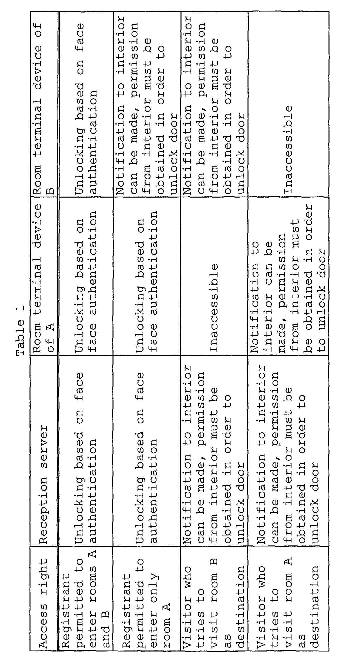
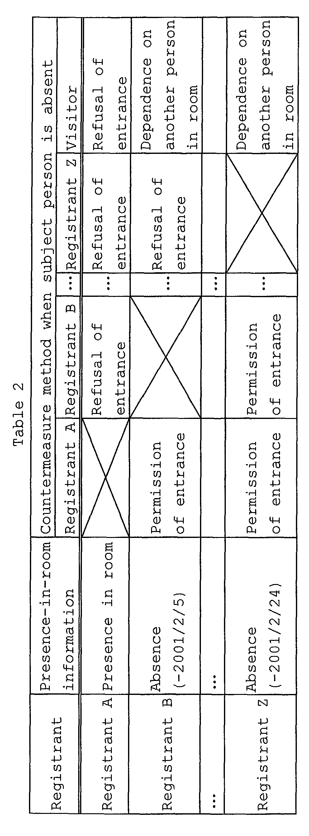
If the person is determined as a "visitor" in the
authentication process at the reception server 104, a
screen which suggests the visitor to input information
indicating a visiting destination such as a room number
of the visiting destination is displayed together
with the face image of the visitor on the display
section 112. For example, in the example shown in
FIG. 22, a display region 151, operation button 152 and
display region 153 are displayed together with
the guidance "please select an object room" on the
display section 112. In this case, assume that the
touch panel used as the information input section 135
is contained in the display section 112.
The display region 151 is a region in which the
face image of the visitor is displayed. The operation
button 152 includes a ten-key pad used to input a room
number, an "OK" key which specifies confirmation of the
input, a "correction key (×)" which corrects the input
and the like. The display region 153 is a region in
which information input by use of the operation button
152 is displayed.
If an input screen of information indicating the
visiting destination as shown in FIG. 22 is displayed
on the display section 112, the visitor inputs
information indicating the visiting destination. When
the visitor inputs information indicating the visiting
destination, the reception server 104 transfers the
face image of the visitor to the room terminal device
105 of the visiting destination.
As a result, a notification screen as shown in
FIG. 23 is displayed on the display section 122b of the
visiting destination. In the example shown in FIG. 23,
a display region 154 in which the face image of the
visitor is displayed, entrance permission button 155,
entrance effective period setting button 156 and
entrance refusal button 157 are displayed. In this
case, assume that the touch panel used as
the information input section 145 is contained in the
display section 122b.
The display region 154 is a region in which the
face image of the visitor is displayed. The entrance
permission button 155 is depressed when permission of
entrance is given to the visitor. The entrance
effective period setting button 156 is operated to set
an effective period of entrance with respect to the
visitor. The entrance refusal button 157 is depressed
when entrance of the visitor is refused.
The face feature amount registration section 134
registers the face feature amount extracted by the face
feature amount extracting section 132 into the
registration information holding device 116 when the
"visitor" is determined by the similarity determining
section 133 and the visitor is permitted to enter the
building 101 by a person who exists in the room 103 of
the visiting destination. At the same time, the face
feature amount registration section 134 broadcasts the
face feature amount to the registration information
holding sections 126 of the room terminal devices 105.
The door control device 117 controls the door 102a
of the common doorway 102 of the whole building 101
according to the result of determination by the
similarity determining section 133. The door control
device 117 instantaneously unfastens the electric lock
102b of the door 102a so as to permit the visitor to
enter the building 101 when the "registrant" is
determined by the similarity determining section 133.
Further, in a case where the "visitor" is
determined by the similarity determining section 133
and the visitor is permitted to enter the building 101
by the operation of the door unlocking section 146 of
the room terminal device 105 of the visiting
destination, the door control device 117 first
registers the face feature amount information into the
registration information holding device 116 and then
unfastens the electric lock 102b of the door 102a so as
to permit the visitor to enter the building 101.
The information input section 135 is used to input
information which specifies a room of a visiting
destination. For example, the information input
section 135 is configured by a touch panel contained in
the display section 112 or a ten-key pad separately
provided.
Further, as the information input section 135,
a microphone 114 used to input a voice of a visitor or
the like is contained. The microphone 114 as the
information input section 135 is used by a visitor to
transmit his voice to a person in the room 103 of the
visiting destination. For example, when the visitor
specifies a room of the visiting destination by use of
the touch panel contained in the display section 112,
the microphone 114 transmits a voice to the room
terminal device disposed at the entrance of the room
103 of the visiting destination. As a voice
transmission system between the reception server 104
and each of the room terminal devices 105,
a transmission system using a network based on digital
compression can be used as well as a transmission
system using a normal analog signal.
Next, each of the sections of the room terminal
device 105 is explained in detail.
The camera 121 photographs a face image of a
person standing in front of the door 103a of the room
103. The camera 121 is disposed outside the door 103a
at the entrance of the room 103. The camera 121 may be
the same as the camera 111 of the reception server 104.
For example, when the visitor registered at the
reception server 104 enters the building 101 and
arrives at the room 103 which is the visiting
destination, the camera 121 photographs the face image
of the visitor.
The face region detecting section 141 detects
a face region from an image input from the camera 121.
The face region detecting section 141 may be the same
as the face region detecting section 131 of the
reception server 104. The face feature amount
extracting section 142 may be the same as the face
feature amount extracting section 132 of the reception
server 104.
The registration information holding device 126
holds a face feature amount broadcasted from the
registration information holding device 116 of the
reception server 104. Of course, face information
items of the existing registrants are held in the
registration information holding device 126. For
example, when the visitor registers the face by use of
the reception server 104 at the common doorway 102 of
the building 101, registration information such as the
face feature amount of the visitor is transferred to
the registration information holding device 126 of each
room terminal device 105. The storage medium used in
the registration information holding device 126 is the
same as that of the registration information holding
device 116 of the reception server 104.
The similarity determining section 143 compares
the face feature amount derived by use of the face
feature amount extracting section 142 with the face
feature amounts registered in the registration
information holding device 126. The similarity
determining section 143 authenticates a person based on
the face image photographed by the camera 121. The
similarity determining section 143 determines whether
the person whose face image is photographed by the
camera 121 is a "registrant permitted to enter the room
103", "registrant who is not permitted to enter the
room 103", "visitor who obtains permission of entrance
from the room 103" or "another person".
For example, if the similarity corresponding to a
person who gives the highest degree of similarity among
all of the registrants and the visitors whose face
information items are registered is smaller than a
preset threshold value, the similarity determining
section 143 determines that the person is "another
person". If the similarity corresponding to a person
who gives the maximum similarity exceeds the preset
threshold value, the similarity determining section 143
determines that the person is the person who gives the
maximum similarity.
After determining the person, the similarity
determining section 143 determines the attribute of the
thus determined person. The attribute of the person is
information stored in the registration information
holding device 126 in relation to the face feature
amount. For example, as the attribute of the person, a
"registrant permitted to enter the room", "registrant
who is not permitted to enter the room", "visitor" and
the like are set. The similarity determining section
143 determines the person whose face image is
photographed by the camera 121 based on the attribute
of the person.
The method of comparison with the feature amount
of the registration information holding device 126 is
the same as that of the similarity determining section
133 of the reception server 104.
Assuming that the electric lock 103b of the door
103a controlled by the door control device 127 cannot
be unfastened by use of physical unlocking means, the
following explanation is made. However, the electric
lock 103b may be so designed that it can be physically
unfastened in a condition that face information is
necessarily registered when the door 103a is unlocked.
If the physical unlocking means is used, a key which is
extremely difficult to duplicate or pick is preferably
used as the physical unlocking means.
If the similarity determining section 143
determines that the person is a "registrant permitted
to enter the room", the door control device 127
immediately unfasten the electric lock 103b of the door
103a. In other cases, the door control device 127 does
not immediately unfasten the electric lock 103b and the
output devices 112 and 113 notify the internal portion
of the room 103 about the result of determination by
the similarity determining section 143.
Next, the process based on the similarity
determination process by the similarity determining
section 143 is explained.
FIG. 24 is a flowchart for illustrating the
process based on the similarity determination.
Further, the following table 1 shows the relation of
determination at the reception server, determination at
the room terminal device of the room A, determination
at the room terminal device of the room B with respect
to various access rights.
The access rights of the table 1 show the results
of determination by the similarity determining section
143. The operations of the output devices ( display
sections 122a, 122b, speakers 123a, 123b), door control
device 127 and the like are determined based on the
access right obtained as the result of determination by
the similarity determining section 143.
For example, as described before, the display
section 122a and speaker 123a used as the output
devices are disposed outside the door 103a. The
display section 122a and speaker 123a output the
contents of determination to the outside of the door
103a by use of a screen and voice according to the
result of determination by the similarity determining
section 143.
Further, the display section 122b and speaker 123b
used as the output devices are disposed inside the door
103a, that is, in the room 103. The display section
122b and speaker 123b output the contents of
determination to the outside of the door 103a by use of
a screen and voice according to the result of
determination by the similarity determining section
143.
For example, if the determination result indicates
that the person is a "registrant permitted to enter the
room" (steps S100, S101), guidance which suggests the
person to enter the room is displayed on the display
section 122a disposed outside the room (step S105).
When the guidance to suggest the entrance is displayed
on the display section 122a, the door unlocking section
146 causes the door control device 127 to unfasten the
electric lock 103b of the door 103a (step S106).
Further, if the determination result indicates
that the person is a "registrant who is not permitted
to enter the room" (steps S100, S102) or a "registrant
permitted to enter the building by a person in the
room" (steps S100, S103), information indicating that
a person who wants to enter the room is present in
front of the room is output to the display section 122b
and speaker 123b disposed inside the room (step S107).
When the presence of the person who wants to enter the
room is notified by use of the display section 122b and
speaker 123b, the door unlocking section 146 unfastens
the electric lock 103b of the door 103a according to
the operation by a person in the room.
For example, the display section 122b displays the
face image of the person photographed by the camera 121
and standing outside the room and the speaker 123b
sounds a chime. As a result, a person in the room
recognizes that the person who wants to enter the room
is present in front of the room. When recognizing the
person who desires to enter the room, the person in the
room confirms the person who desires to enter the room
according to the image displayed on the display section
122b or a voice from the speaker 123b. If permitting
the entrance of the person who desires to enter the
room, the person in the room specifies unfastening of
the electric lock of the door 103a by use of an
operating section (not shown) or the like. Then, the
door unlocking section 146 causes the door control
section 147 to unfasten the electric lock 103b of the
door 103a (step S108).
Further, if the determination result indicates
that the person is a "person (another person) who is
neither a registrant nor a person who obtains
permission of entrance from the room" (steps S100,
S104), the access inhibiting section 147 inhibits
access to any one of the rooms from the exterior (step
S109). At this time, for example, the devices such as
the output devices ( display sections 122a, 122b,
speakers 123a, 123b) and door control device 127 are
not operated.
That is, the operation for sounding the chime in
the room 103 of the visiting destination of the
"visitor" is not performed at all in the rooms other
than the room which the visitor is permitted to enter
when the face is registered at the reception
server 104. Therefore, a visit of the visitor who is
permitted to enter the room at the reception desk is
neglected in the other rooms. As a result, it is
possible to prevent the visitor from accessing
the rooms other than the room which the visitor
specifies as a visiting destination.
If a person who comes in front of the door 102a of
the common doorway 102 wants to enter a certain one of
the rooms 103, whether permission of entrance is issued
or not is displayed on the indoor display section 122b
as shown in FIG. 23 and specified by a person in the
room. Thus, the visitor can enter the building 101
only when permission of entrance is issued by a person
in the room 103 of the visiting destination. Further,
when the fact that a person who desires to enter the
room has visited is notified by use of the room
terminal device 105, whether permission of entrance is
issued or not is displayed on the indoor display
section 122b as shown in FIG. 23 and specified by
a person in the room. Thus, the visitor can enter the
room only when permission of entrance is issued by the
person in the room 103 of the visiting destination.
The door unlocking section 146 is operated
according to permission of entrance specified by
a person in the room with respect to a person other
than the registrants of the respective rooms 103.
The table 1 shows procedures which persons having
different access rights can take. According to the
table 1, a registrant who is permitted to enter the
room A and room B can pass the reception desk and enter
the room A and room B based only on face
authentication. A registrant who is permitted to enter
only the room A can pass the reception desk, enter
the room A based only on face authentication and enter
the room B based on face authentication and permission
issued from the room B.
Further, a visitor who visits the room A (or
room B) as a visiting destination) can pass the
reception desk and enter the room A (or room B) based
on face authentication and permission issued from the
room but the visitor is inhibited from accessing to the
room B (or room A) which is not specified as the
visiting destination.
For example, when a visitor who comes in front of
the door 102a of the common doorway 102 inputs a room
number as information indicating a room of the visiting
destination by use of the information input section
135, when a visitor who has entered the building 101
comes in front of the door 103a of the room 103 of the
visiting destination input at the reception server 104
or when a registrant who is not permitted to enter the
room 103 of the visiting destination comes in front of
the door 103a, the face image of the person who comes
in front of the door is displayed on the indoor output
device (display section 122b) as shown in FIG. 23.
The person in the room who receives a visit depresses
the entrance permission button 155 or entrance refusal
button 157 while watching the image displayed on the
display section 122b. The door unlocking section 146
controls the unfastening operation of the electric lock
103b of the door 103a according to the button input by
the person in the room.
Further, temporary permission of entrance is given
to a visitor. Therefore, as shown in FIG. 23, it is
assumed that the person in the room who has received
the visit of the visitor can specify the effective
period of time of the access right with respect to the
visitor by use of the entrance effective period setting
button 156 when the entrance permission button 155 is
input.
The information input section 145 functions as
means by use of which the visitor accesses the room 103
of the visiting destination. For example, if the
microphone 124a is used as the information input
section 145, the visitor can input a voice to the
microphone 124a and transmit a message to the room 103.
Next, the flow of a process performed when a
registrant who is previously permitted to enter the
building 101 enters an objective room 103 and the flow
of a process performed when a visitor who is
temporarily permitted to enter the building 101 enters
the room 103 of the visiting destination are explained.
First, the flow of the process performed when
a registrant who is previously permitted to enter the
building 101 enters an objective room 103 is explained
with reference to the flowchart shown in FIG. 25.
When the registrant stands in front of the door
102a of the common doorway 102 of the building 101
(step S111), the reception server 104 detects a face
image from the image photographed by the camera 111
(step S112). Then, the reception server 104 having
detected the face image collates the detected face
image with the dictionary data registered in the
registration information holding device 116. If the
person is authenticated as a registrant based on the
collation result, the reception server 104 causes the
door control device 127 to unfasten the electric lock
102b of the door 102a of the common doorway 102 of the
whole building 101 and permits the person to enter the
building 101 (step S113).
When the registrant who has entered the building
101 arrives at an objective room 103 in the building
101 and stands in front of the door 103a, the room
terminal device 105 causes the camera 121 to photograph
an image of the registrant. The room terminal device
105 collates the face image detected from the
photographed image with the dictionary data held in
the registration information holding device 126.
If the registrant is successfully authenticated based
on the collation process, the door terminal device 105
causes the door control device 127 to unfasten the
electric lock 103b of the door 103a and permits
entrance (step S114). Thus, the registrant can enter
the room which is previously permitted to enter based
only on the face authentication (step S115).
Next, the flow of the process performed when a
visitor who is temporarily permitted to enter the
building 101 enters the room 103 of the visiting
destination is explained with reference to the
flowchart shown in FIG. 26.
When the visitor stands in front of the door 102a
of the common doorway 102 of the building 101
(step S121), the reception server 104 detects a face
image from the image photographed by the camera 111
(step S122). Then, the reception server 104 having
detected the face image collates the detected face
image with the dictionary data registered in the
registration information holding device 116. If the
visitor is authenticated as a person who is not
a registrant based on the collation result, the
reception server 104 displays guidance to the effect
that the visiting destination is specified as shown in
FIG. 22 on the display section 112. The visitor who
observes the guidance screen inputs a room number of
the visiting destination by use of the operation button
152 (step S123).
When the room number of the visiting destination
is input, the reception server 104 transmits the face
image photographed by the camera 111 to the room
terminal device 105 disposed at the entrance of the
room 103 of the visiting destination. When receiving
the face image of the visitor from the reception server
104, as shown in FIG. 23, the room terminal device 105
notifies that the visitor has come and displays a
notification screen which specifies permission or
inhibition of entrance on the indoor display section
122b (step S124). At this time, a person in the room
103 of the visiting destination confirms the face image
displayed on the display section 122b and permits
entrance by depressing the entrance permission button
155 (step S125).
If permission of entrance is issued in the room
103 of the visiting destination, the reception server
104 registers the face image of the visitor into the
registration information holding device 116 and
transmits the face image of the visitor to the room
terminal device 105. After registering the face image
of the visitor into the registration information
holding device 116, the reception server 104 causes the
door control device 117 to unfasten the electric lock
102b of the door 102a of the common doorway 102 and
permits the visitor to enter the building 101 (step
S126).
When the visitor who has entered the building 101
arrives at the room 103 of the visiting destination in
the building 101 and stands in front of the door 103a
at the entrance, the room terminal device 105 causes
the camera 121 to photograph an image of the
registrant. The room terminal device 105 collates the
face image detected from the photographed image with
the dictionary data held in the registration
information holding device 126. If the visitor is
authenticated as a visitor who obtains permission of
entrance based on the collation process, the door
terminal device 105 makes a call which notifies a
person in the room of a visit of the visitor (step
S127). The call is made by sounding a chime, for
example.
When receiving the call which notifies the visit
of the visitor, the person in the room confirms the
visitor by displaying the face image photographed by
the camera 121 on the display section 121.
Thus, the person in the room permits entrance of the
visitor. In response to permission of entrance made by
the person in the room, the room terminal device 105
causes the door unlocking section 146 to unfasten the
electric lock 103b of the door 103a (step S128). When
the electric lock 103b of the door 103a is unfastened,
the visitor can enter the room 103 of the visiting
destination (step S129).
If the visitor tries to access a room other than
the room which is permitted to enter, the room terminal
device 105 does not authenticate the person who
accessed as a visitor who obtains permission of
entrance. This is because the door terminal device 105
does not receive the face image of the visitor from the
reception server 104. If the room terminal device 105
does not authenticate the visitor as a visitor who
obtains permission of entrance, it does not permit
access to the room by making a call, for example.
As a result, it becomes possible to prevent the visitor
from accessing the room other than the room which is
permitted to enter.
Thus, according to the sixth embodiment, the
temporary entrance/exit management process for a person
other than the registrant can be performed. That is,
when access is made to the door, it is always necessary
to show the face and limitation of access to the door
can be imposed on three types of response means of "the
door is unlockable", "only notification to the internal
section is possible" and "access is impossible"
according to the result of individual authentication of
the face. Thus, even when a visitor or a person who is
not normally permitted to enter the room or the
building is temporarily permitted to enter the place,
the entrance can be managed without losing the
security. Further, the influence on a person who has
no direct relation with the visitor can be suppressed
to minimum by inhibiting access to a place other than
the place which is permitted to enter.
Next, the seventh embodiment is explained.
The seventh embodiment is an entrance management
apparatus which automatically detects the dishonest
behavior of a person who temporarily obtains permission
of entrance and then performs the access limiting
operation in addition to the process of the sixth
embodiment. The seventh embodiment is explained in
detail below.
FIG. 27 schematically shows the configuration of
an entrance management apparatus according to the
seventh embodiment and the whole configuration of
a building such as an apartment house to which the
entrance management apparatus is applied. As shown in
FIG. 27, the seventh embodiment is different from the
sixth embodiment in that an authentication history
server 107 used as authentication history holding means
is additionally provided. Since the other portions are
the same as those of the sixth embodiment, the
explanation for the same portions is omitted and only
the different portions are explained.
The authentication history server 107 is disposed
near a reception server 104, for example. The
authentication history server 107 is connected to the
reception server 104 and room terminal devices 105 via
a network circuit 106. The authentication history
server 107 holds (stores) the whole authentication
history (including authentication time, authentication
result, authentication place, face image input at the
time of authentication, face feature information and
the like) in each of the room terminal devices 105 and
reception server 104. Further, the authentication
history server 107 also holds a dishonest accessing
person list 107a used to register persons who perform
dishonest acts together with corresponding
authentication histories.
A similarity determining section 133 of the
reception server 104 performs the same process as the
similarity determination process explained in the sixth
embodiment. For example, the process up to the process
to determine a person who stands in front of a door
102a of a common doorway 102 is the same as the process
in the sixth embodiment.
In the seventh embodiment, the similarity
determining section 133 also performs a process of
collation with information in the authentication
history server 107 in addition to the process of the
sixth embodiment. That is, the similarity determining
section 133 determines that the visitor is a dishonest
accessing person when the similarity with a person
registered as a dishonest accessing person in the
dishonest accessing person list 107a of the
authentication history server 107 exceeds a preset
threshold value. Further, in the seventh embodiment,
any access (entrance into and notification to
the objective room by authentication in each room
terminal device 105, entrance into the building 101 by
authentication at the reception server 104) by a person
who is determined as the dishonest accessing person is
refused.
A similarity determining section 143 of the room
terminal device 105 performs the same process as the
similarity determination process explained in the sixth
embodiment. For example, the process up to the process
for determining a person who stands in front of a door
103a of a room 103 is the same as the process in the
sixth embodiment.
In the seventh embodiment, like the similarity
determining section 133 of the reception server 104,
the similarity determining section 143 also performs a
process of collation with information in the dishonest
accessing person list 107a of the authentication
history server 107 in addition to the process of the
sixth embodiment. That is, the similarity determining
section 143 determines that a person who stands in
front of the door 103a is a dishonest accessing person
when the similarity for a specified person among the
dishonest accessing persons exceeds a preset threshold
value.
Each authentication history obtained in the
authentication (similarity determination) process is
transferred to the authentication history server 107.
Therefore, the authentication history obtained in each
of the reception server 104 and room terminal devices
105 is held in the authentication history server 107.
The authentication history contains authentication
time, authentication result, authentication place (the
room terminal device in which the authentication
process is performed), face image used for the
authentication process, face feature information
extracted from the face image and the like.
The authentication history held in the
authentication history server 107 is used to form the
dishonest accessing person list 107a. A dishonest
accessing person is determined by performing the
authentication process based on the face image
according to the dishonest accessing person list 107a.
As a result, even if a person has entered the building
101 for the first time, whether the person is a
dishonest accessing person or not can be recognized and
it is possible to refuse access to each room 103.
For example, assume that the number of times by
which dishonest access is made is X and the threshold
value of the number of dishonest access times which is
used as a criterion to determine a dishonest accessing
person is Y. When the number X of dishonest access
times by a certain person exceeds the threshold value
Y, the authentication history server 107 adds
information of the person to the dishonest accessing
person list 107a.
In an example shown in FIG. 28, if the threshold
value of the number of dishonest access times is set to
"1" (Y = 1) and when a person who is permitted to
access the room A tries to access the room B, the
person is registered as a dishonest accessing person
into the dishonest accessing person list 107a. As a
result, the person who is registered as a dishonest
accessing person into the dishonest accessing person
list 107a is hereafter refused to access the reception
server 104 and each of the room terminal devices 105.
The output devices ( display sections 122a, 122b,
speakers 123a, 123b) of each of the room terminal
devices 105 have the same configuration as those of the
sixth embodiment. Further, in the seventh embodiment,
the authentication history held in the authentication
history server 107 can be confirmed by use of the above
output devices. For example, each room terminal device
105 reads out an authentication history relating to a
corresponding one of the rooms 103 from information in
the authentication history server 107 and causes the
readout authentication history to be displayed on the
indoor display section 122b.
As a result, in each of the rooms 103, the
authentication history can be confirmed and whether a
dishonest access is made or not can be determined.
Further, in the seventh embodiment, it is assumed
that only the authentication history of a corresponding
one of the rooms 103 can be confirmed for each room 103
by taking the privacy of each registrant into
consideration. If there is no problem of privacy and
the like, it is possible to confirm the authentication
histories of all of the rooms or the authentication
histories of the other rooms at the reception server
104 or each of the room terminal devices 105. In a
case where only the manager can be permitted to confirm
the authentication histories of all of the rooms or the
authentication histories of the other rooms, it is
possible to set a password number used to authenticate
the manager and permit the manager to confirm all of
the histories only when the password number of the
manager is correctly authenticated.
Thus, according to the seventh embodiment, a
doubtful behavior of a person who is temporarily
permitted to enter can be automatically detected. That
is, it is always necessary to show his face when he
accesses the door and limitations of access to the door
can be imposed on three types of response means of "the
door is unlockable", "only notification to the internal
section is possible" and "access is impossible"
according to the result of individual authentication of
the face. Thus, it is possible to automatically detect
that a person who is temporarily permitted to enter one
of the rooms of one building or part of a site
dishonestly accesses a place other than the previously
permitted place and give no more permission of entrance
to the dishonest accessing person.
Next, the eighth embodiment is explained.
The eighth embodiment is an entrance management
apparatus which automatically registers information
indicating that a person is present or not in a room by
performing the face authentication process at the time
of exit and limit access to the room by another person
while he is absent.
Now, the eighth embodiment is explained in detail
below.
FIG. 29 schematically shows the configuration of
the entrance management apparatus according to the
eighth embodiment and the whole configuration of
a building such as an apartment house to which the
entrance management apparatus is applied. The eighth
embodiment is different from the sixth embodiment in
that a presence-in-room management server 108 used as
presence-in-room management information holding means
is additionally provided and a camera is disposed on
the indoor side of each of the room terminal devices
105 to authenticate the face of a person who exits or
leaves the room. Since the other portions are the same
as those of the sixth embodiment, the explanation for
the same portions is omitted and only the different
portions are explained.
FIGS. 30, 31 schematically show the configuration
of the room terminal device 105 according to the eighth
embodiment. The eighth embodiment is different from
the sixth embodiment in that a camera 121b used to
acquire (input) at least a face image of a person is
disposed inside a door 103a. The other portions are
the same as those of the sixth embodiment. A camera
disposed outside the door 103a is denoted by a
reference symbol 121a.
FIG. 32 is a block diagram showing the whole
configuration of the room terminal device 105 according
to the eighth embodiment. Further, the eighth
embodiment is different from the sixth embodiment in
that the camera 121b disposed inside the door 103a and
a control device 125b for the camera 121b are
additionally provide and the other portions are the
same as those of the sixth embodiment.
That is, as shown in FIG. 32, a control device
125a of an outdoor side room terminal device 105a
includes a face region detecting section 141a, face
feature amount extracting section 142a and face
similarity determining section 143a. The face region
detecting section 141a detects a face region from a
face image photographed by the camera 121a. The face
feature amount extracting section 142a extracts a face
feature amount based on the face region detected by the
face region detecting section 141a. The face
similarity determining section 143a determines the
similarity between the feature amount extracted by the
face feature amount extracting section 142a and
reference feature amounts registered in a registration
information holding device 126.
Further, the control device 125b of an indoor side
room terminal device 105b includes a face region
detecting section 141b, face feature amount extracting
section 142b and face similarity determining section
143b. The face region detecting section 141b detects
a face region from a face image photographed by the
camera 121b. The face feature amount extracting
section 142b extracts a face feature amount based on
the face region detected by the face region detecting
section 141b. The face similarity determining section
143b determines the similarity between the feature
amount extracted by the face feature amount extracting
section 142b and the reference feature amounts
registered in the registration information holding
device 126.
Respective sections shown in FIG. 32 are the same
as corresponding sections of the same names shown in
FIG. 20. Further, an information input section 145a on
the outdoor side and an information input section 145b
on the indoor side are the same as the information
input section 145 shown in FIG. 20.
The respective sections are explained below but
the explanation for portions which are the same as
those of the sixth embodiment is omitted.
The presence-in-room management server 108 is
disposed near a reception server 104. The presence-in-room
management server 108 is connected to the
reception server 104 and each room terminal device 105
via a network circuit 106. The presence-in-room
management server 108 holds presence-in-room management
information for all of the registrants. The presence-in-room
management information indicates that the
registrant is present or absent in the room and time at
which the registrant comes back if the registrant is
absent. Further, the presence-in-room management
server 108 holds a registrant list 108a used to inhibit
access to a corresponding room while the registrant is
being absent.
The following table 2 indicates an example of the
registrant list 108a.
As shown in the table 2, the registrant list 108a
collectively shows the correspondence relation between
the access rights and presence-in-room information
items of respective registrants associated with
entrance into corresponding rooms. In the registrant
list 108a, items of "presence-in-room information" and
"countermeasure taken at the time of absence" are
provided for each registrant. In the item of
"presence-in-room information", the presence-in-room
state of each registrant is stored. For example, in
the table 2, it is understood that information
indicating that the registrant A is present in the
room, the registrant B will be absent until February 5,
2001 and the registrant Z will be absent until February
24, 2001 is registered.
Further, in the column of "countermeasure taken at
the time of absence of the subject registrant", the
type of access right given to another registrant and
a visitor when the subject registrant is absent is
stored. For example, in the table 2, the condition is
so set that any one of the registrant and visitor is
refused to enter the room when the registrant A is
absent. That is, in the table 2, the condition is so
set that no one is permitted to enter the room if the
registrant A is not present. Further, the condition is
so set that the registrant A is permitted to enter the
room of the registrant B irrespective of the
presence-in-room information of the registrant B, but
the registrant Z cannot enter the room if the
registrant B is absent.
Further, in the item of a "visitor" of the column
of "countermeasure taken at the time of absence of the
subject registrant", information indicating the way to
deal with a person who is temporarily permitted to
enter the place is stored. "No entrance" as the
countermeasure indicates the condition that entrance is
inhibited. Further, "dependence on another person in
room" as the countermeasure indicates the condition
that if another person is present in the corresponding
room when the subject registrant is absent,
determination of permission or inhibition of entrance
is made dependent on the person in the room.
Thus, the registrant list 108a as shown in the
table 2 is set for the registrants for all of the rooms
103 to which entrance limitation is applied in the
building 101. The adequate entrance/exit condition can
be set according to the presence-in-room state of
a person in each room 103 by use of the registrant list
108a.
If a person is determined as a registrant by use
of the similarity determining section 133, the
reception server 104 causes the door control device 117
to unfasten the electric lock 102b of the door 102a of
the common doorway 102 of the registrant.
If the person is determined as a visitor, the
reception server 104 registers face information of the
visitor into the face feature amount registration
section 134 and suggests the visitor to input
information indicating a room such as a room number of
the visiting destination by use of the information
input section 135. If the visitor inputs information
indicating the room, the reception server 104
determines permission or inhibition of access of the
visitor to the room based on the registrant list 108a
corresponding to the specified room.
For example, if the visitor is permitted to enter
the room based on the registrant list 108a, the
reception server 104 notifies the indoor side output
device (display section 122b) of the room 103 of the
visiting destination that the visitor has come. The
person in the room of the visiting destination having
received the notification specifies permission or
inhibition of entrance of the visitor. If the person
in the room of the visiting destination permits
entrance of the visitor, the door unlocking section 146
unfastens the electric lock 103b of the door 103a.
On the other hand, if entrance of the visitor is
inhibited based on the registrant list 108a, the
reception server 104 refuses entrance of the visitor
without unfastening the electric lock 102b of the
door 102a. If entrance of the visitor is thus refused,
the output device (display section 112) of the
reception server 104 notifies that there is no person
who can permit entrance in the room of the visiting
destination.
The similarity determining sections 143a, 143b of
the room terminal device 105 perform the same
similarity determining process as the similarity
determining process explained in the sixth embodiment.
For example, the process up to the process for
determining a person who stands in front of the door
103a of the room 103 is the same as that in the sixth
embodiment. In the eighth embodiment, when a person
who is authenticated as a registrant enters the room
103, the room terminal device 105 transmits information
indicating that the registrant is present in the room
to the presence-in-room management server 108. Thus,
the presence-in-room management server 108 sets the
item "presence-in-room information" of the registrant
list 108a to "presence in room".
On the other hand, if the registrant exits the
room 103 to the exterior, the room terminal device 105
transmits information indicating that the registrant is
absent in the room to the presence-in-room management
server 108. Thus, the presence-in-room management
server 108 sets the item "presence-in-room information"
of the registrant list 108a to "absence in room".
When a person enters the room 103, the room
terminal device 105 reads out entrance limitation
information associated with the person based on
information in the presence-in-room management
server 108. The room terminal device 105 controls the
fastening/unfastening state of the electric lock 103b,
notification to the internal section of the room 103
and permission/refusal of entrance based on the readout
entrance limitation information associated with the
person.
Further, when a person exits the room 103 to the
exterior, the room terminal device 105 performs the
authentication process for the person who exits the
room. By performing the authentication process, the
room terminal device 105 notifies exit of the person
specified as the result of authentication to the
presence-in-room management server 108 and unfastens
the electric lock 103b of the door 103a.
The output devices (liquid crystal display
monitors 122a, 122b, speakers 123a, 123b) of the room
terminal device 105 are the same as those of the sixth
embodiment.
For example, presence-in-room information for each
room can be displayed on the display section 122b on
the indoor side of the room 103 based on the
registration information list 108a in the presence-in-room
management server 108. Therefore, a person in
each room can confirm the presence-in-room state of
each room 103 and the setting state of the access right
of each registrant. Further, in the eighth embodiment,
it is assumed that, in each room terminal device 105,
only the presence-in-room information of a
corresponding one of the rooms can be confirmed in
order to protect the privacy of each of the registrants
in the building 101.
Also, it is possible to set a password number of
a manager who manages the whole building 101 and permit
all of the presence-in-room information items in the
presence-in-room management server 108 to be confirmed
only when the password number of the manager is
authenticated.
Further, a password number of a person who has
a right to change the setting of the registration
information list 108a may be set. In this case, it is
possible to change the setting contents of the
registration information list 108a only when the
password number of the person who has the right to
change the setting of the registration information list
108a is authenticated.
The information input sections 145a, 145b of the
room terminal device 105 have the same function as that
of the information input section explained in the sixth
embodiment. When a person exits the room 103, it is
possible for the person who exits the room to input
an absence period by use of the information input
section 145b. That is, when the registrant exits the
room 103, the room terminal device 105 authenticates
the person who exits the room. The room terminal
device 105 transmits information indicating that the
authenticated registrant is "absent" to the presence-in-room
management server 108.
At this time, the room terminal device 105
displays guidance suggesting the registrant to input
the absence period on the display section 122b.
The registrant who exits the room inputs the absence
period according to the guidance by use of the
information input section 145b if the absence period is
previously known. If the registrant who exits the room
inputs the absence period, the room terminal device 105
transmits the absence period of the registrant to
the presence-in-room management server 108. The
presence-in-room management server 108 registers the
registrant who is absent and the absence period into
the registration information list 108a based on
information transmitted from the room terminal
device 105. Thus, it is also possible to notify
a person who visits during the absence about the
absence period.
FIG. 33 is a view showing an example of an input
screen indicating an absence period displayed on the
display section 122b when the registrant exits the
room. In FIG. 33, a display example of a case wherein
the information input section 145b is configured by
a touch panel contained in the display section 122b is
shown. In the example of the absence period input
screen shown in FIG. 33, an operation button 158 used
to input an absence period and the like, a display
section 159 used to display the input absence period
and an input cancel button 160 used to correct the
input contents are displayed.
Next, the flow of a process for controlling
permission of entrance for a registrant and visitor
based on presence-in-room information is explained.
The flowchart shown in FIG. 34 illustrates the
flow of a process performed after a registrant and
visitor arrive at a common doorway 102 of the whole
building 101 until they enter respective rooms 103.
The explanation is made below with reference to the
flowchart of FIG. 34.
When a person stands in front of the door 102a of
the common doorway 102 of the building 101, the
reception server 104 authenticates a face based on a
face image input from the camera 111 (step S131).
Then, the reception server 104 determines whether the
person is a visitor or not based on the result of
authentication (step S132). If it is determined as the
result of determination that the person is not a
visitor (the person is a registrant), the reception
server 104 unfastens the electric lock 102b of the door
102a of the common doorway 102 and permits the person
to enter the building 101 (step S133).
When the registrant who has entered the building
101 arrives at an objective room 103 in the building
101, he stands in front of the door 103a. As a result,
the room terminal device 105 causes the camera 121a to
photograph a face image of the registrant. After
photographing the face image, the room terminal device
105 performs the authentication process for the
photographed face image (step S134). If a person with
the photographed face image is specified by the
authentication process, the room terminal device 105
accesses the presence-in-room management server 108 and
reads out the registrant list 108a of the corresponding
room 103 (step S135). After reading out the registrant
list 108a, the room terminal device 105 determines
whether or not the present registrant is permitted to
enter the room based on the registrant list 108a
(step S136).
If it is determined in the above determination
process that the present registrant is permitted to
enter the room, the room terminal device 105 causes the
door control section 127 to unfasten the electric lock
of the door 103a and permits the present registrant to
enter the room 103 (step S137). On the other hand, if
it is determined in the above determination process
that the present registrant is not permitted to enter
the room, the room terminal device 105 outputs a
message indicating the absence of a registrant who is
required for permitting entrance on the display section
122a on the outdoor side and keeps the electric lock
103b of the door 103a fastened (step S138).
Further, if it is determined as the result of
determination in the step S132 that the person is a
visitor, the reception server 104 displays an input
screen of a visiting destination used to inquire about
the visiting destination as shown in FIG. 22 on the
display section 112 of the common doorway 102. The
visitor inputs a room number of the objective visiting
destination by use of the operation button 152 of the
input screen of the visiting destination displayed on
the display section 112 (step S139).
When the room number of the visiting destination
is input, the reception server 104 reads out the
registrant list 108a of the corresponding room from the
presence-in-room management server 108 (step S140).
After reading out the registrant list 108a, the
reception server 104 determines whether or not a
registrant who is required for permitting entrance is
present in the room (step S141). If it is determined
as the result of determination that the registrant
required for permitting entrance is absent, the
reception server 104 outputs a message indicating the
absence of the registrant required for permitting
entrance on the display section 112 of the common
doorway 102 and keeps the electric lock 102b of the
door 102a of the common doorway 102 in the fastened
state (step S142).
If it is determined as the result of determination
in the step S141 that the registrant required for
permitting entrance is present in the room, the
reception server 104 transmits a face image
photographed by the camera 111 to the room terminal
device 105 of the room 103 of the visiting destination.
The room terminal device 105 which has received the
face image of the visitor displays a screen notifying a
visit of the visitor as shown in FIG. 23 on the display
section 122b on the indoor side.
Thus, the person in the room recognizes that the
visitor has appeared at the common doorway 102. The
person in the room 103 of the visiting destination who
has received the notification confirms the face image
displayed on the display section 122b and depresses the
entrance permission button (not shown) if he permits
entrance of the visitor. If the entrance permission
button is depressed, the door unlocking section 146 of
the room terminal device 105 transmits a door unlocking
request to the reception server 104. Then, the
reception server 104 causes the door control device 117
to unfasten the electric lock 102b of the door 102a of
the common doorway 102 and permits the visitor to enter
the building 101.
At this time, the reception server 104 registers
the face image of the visitor into the registration
information holding device 116 and transmits the face
image of the visitor to the room terminal device 105 of
the corresponding room (step S143). As a result, the
face image of the visitor is registered into the
registration information holding device 126 of the room
terminal device 105 of the room into which the visitor
is permitted to enter.
The visitor who has entered the building 101
arrives at the room 103 of the visiting destination in
the building 101 and then stands in front of the door
103a at the entrance. Therefore, the room terminal
device 105 causes a camera 121a to photograph a face
image of the visitor. After photographing the face
image, the room terminal device 105 performs the
authentication process for the photographed face image
(step S144). If a person of the photographed face
image is specified by the authentication process, the
room terminal device 105 accesses the presence-in-room
management server 108 to read out the registrant list
108a of a corresponding one of the rooms 103
(step S145). After reading out the registrant list
108a, the room terminal device 105 determines whether
or not a person who can give permission of entrance to
the visitor is present in the room based on
the registrant list 108a (step S146).
If it is determined as the result of determination
that the person who can give permission of entrance to
the visitor is present in the room, the room terminal
device 105 displays a screen notifying a visit of the
visitor as shown in FIG. 23 on the display section 122b
on the indoor side.
As a result, the person in the room recognizes
that the visitor appears in front of the door 102a.
The person in the room 103 of the visiting destination
who receives the notification confirms the face image
displayed on the display section 122b and depresses the
entrance permission button 155 if he permits entrance
of the visitor. If the entrance permission button 155
is depressed, the door unlocking section of the room
terminal device 105 causes the door control device 127
to unfasten the electric lock 103b of the door 103a and
permits the visitor to enter the room 103 (step S147).
If it is determined as the result of determination
in the step S146 that the person is absent in the room,
the room terminal device 105 outputs a message
indicating that the person who can permit entrance is
absent to the display section 122a on the outdoor side
and keeps the electric lock 103b of the door 103a in
the fastened state (step S148).
As described above, according to the eighth
embodiment, the absence-in-room state of the room is
automatically registered in the presence-in-room
management server 108 to control entrance of a person
based on the previously set contents thereof. That is,
the face authentication process is performed not only
when a person enters the room but also when the person
exits the room and the presence-in-room state of the
registrant is registered in the presence-in-room
management server 108. As a result, it becomes
possible to perform an adequate access management
process previously set according to presence-in-room
information and inhibit another person from accessing
a room in which the registrant or the like is absent.
Next, the ninth embodiment is explained.
The ninth embodiment is a stand-alone entrance
management apparatus which can be used only for one
room or one doorway of a building. Of course, like the
sixth to eighth embodiments, the entrance management
apparatus can be realized as the entrance management
apparatus interlocked in the client server system.
The ninth embodiment is the entrance management
apparatus in which daily authentication histories are
held, the authentication history can be observed at any
given time and the growth record and diary of a person
who obtains permission of entrance are automatically
formed. A case where the entrance management apparatus
is applied to one of the rooms of the building shown in
FIG. 15 is explained, for example.
FIG. 35 schematically shows the configuration of
the entrance management apparatus according to the
ninth embodiment. The basic configuration of the
entrance management apparatus according to the ninth
embodiment is the same as that of the room terminal
device 105 in the sixth embodiment shown in FIGS. 17
and 18. As shown in FIG. 35, the ninth embodiment is
different from the sixth embodiment in that an
authentication history holding server 109 used as
authentication history holding means and an
authentication history output device 163 used as
authentication history output means are additionally
provided in the sixth embodiment. Portions which are
the same as those of FIG. 17 are denoted by the same
reference symbols, the explanation thereof is omitted
and only different portions are explained.
The authentication history holding server 109 is
configured by a personal computer or the like. The
authentication history holding server 109 holds the
authentication history in each of the room terminal
devices 105. The authentication history output device
163 includes a personal computer 64 with display and a
printer 65. The authentication history output device
163 outputs the authentication history held in the
authentication history holding server 109 in a preset
form. The authentication history output device 163
permits authentication history information to be
observed and outputs the growth record and diary in a
preferable form, for example.
In the example of FIG. 35, the authentication
history holding server 109 is connected to a control
device 125 via a network circuit 161. The
authentication history output device 163 is connected
to the authentication history holding server 109 via a
network circuit 162.
FIG. 36 is a block diagram showing the whole
configuration of the entrance management apparatus
according to the ninth embodiment. The basic
configuration thereof is the same as the room terminal
device 105 shown in FIG. 32 explained in the sixth
embodiment. The configuration shown in FIG. 36 is
different from that shown in FIG. 32 in that a face
feature amount registration section 144, authentication
history holding server 109 and authentication history
output device 163 are added to the configuration shown
in FIG. 32. Portions which are the same as those of
FIG. 20 are denoted by the same reference symbols and
the explanation thereof is omitted.
The above sections are explained in detail below.
The face feature amount registration section 144
is the same as the face feature amount registration
section 134 of the reception server 104 explained
before. In order to enhance the security, it is
possible to inhibit registration of face feature
amounts if it is not combined with a physical security
device such as a key or a password number input.
Therefore, it is possible to conduct registration of
feature amounts only in the presence of a person such
as a manager who has the right to register the face
feature amount.
The flow of a process up to the process for
determining a person who stands in front of the door
103a of the room 103 by use of the similarity
determining section 143a,143b can be realized in the
same manner as the flow of the process in the sixth
embodiment. In the ninth embodiment, a process for
transferring the determination result (authentication
result) and the face image to the authentication
history holding server 109 is performed in addition to
the operation in the sixth embodiment.
The information input section 145a,145b can be
realized in the same manner as in the sixth embodiment.
The information input section 145a,145b of the ninth
embodiment performs the operation for inputting a
message which is desired to be recorded in the growth
record or diary as voice data or text information in
addition to the operation explained in the sixth
embodiment. For example, after completion of the
authentication process, an inquiry screen 170a as
shown in FIG. 37 is displayed on the display section
122a or 122b. Each registrant can record a desired
message as the history as required according to
guidance displayed on the inquiry screen 170a.
Further, a text message can be automatically input
based on the voice of the registrant by use of the
voice recognition technique.
In the inquiry screen 170a shown in FIG. 37, it is
assumed that a touch panel contained in the display
section 122a or 122b is used as the information input
section 145a,145b. On the inquiry screen 170a, a face
image display region 171, voice memo button 172, text
memo button 173 and cancel button 174 are displayed.
In the face image display region 171, a face image
of a person photographed by the camera 121 and stored
as a history is displayed. The voice memo button 172
is operated when the registrant records a voice
message. As the voice message, the voice itself can be
held as it is or data obtained by converting a voice
into a text message by use of the voice recognition
technique can be held. The text memo button 173 is
operated if a text memo (character data) input by the
registrant is kept recorded. The cancel button 174 is
operated when no memo is kept recorded.
When the text memo button 173 is input, a text
memo input screen 170b as shown in FIG. 37 is displayed
on the display section 122a or 122b. As shown in
FIG. 37, on the text memo input screen 170b, a keyboard
is displayed by use of the touch panel contained in
the display section 122a or 122b. The registrant
inputs a memo (sentence) by depressing keys to operate
the keyboard displayed on the input screen 170b.
A memo (comment) input on the inquiry screen 170a
is held in the authentication history holding server
109 as authentication history information together with
the date, authentication time, authenticator, face
image and the like. FIG. 38 is a view showing an
example of authentication history information held in
the authentication history holding server 109. In the
example shown in FIG. 38, a voice memo as a comment or
a memo based on text is held.
As described before, the authentication history
output device 163 is configured by the personal
computer 164 and printer 165. The authentication
history output device 163 displays or prints out
history information held in the authentication history
holding server 109. For example, the personal computer
164 and printer 165 used as the authentication history
output device 163 are disposed in the room 103.
Therefore, the registrant can display information
of the authentication history holding server 109 by use
of the personal computer 164 in the room 103. Further,
the registrant can print information held in the
authentication history holding server 109 by use of
the printer 165 in the room 103. In addition, the
registrant can confirm whether dishonest access to
the room 103 has been made or not by use of the
authentication history output device 163. It is
possible only for the manager to use the authentication
history output device 163 by use of a password number
or the like.
FIG. 39 is a view showing an output example of
authentication history information by the
authentication history output device 163. FIG. 39
shows an example in which the authentication history
information shown in FIG. 38 is output onto a sheet of
paper. For example, the registrant selects desired
information from the authentication history and
operates the printer 165 to print the selected
information. In this case, the printer 165 prints the
face image, memo (comment), date and the like
corresponding to the information selected by the
registrant in a form selected by the registrant. Thus,
information held as the authentication history can be
printed in an album form or diary form.
As described above, according to the ninth
embodiment, in the apparatus which controls the
locking/unlocking state of the door of the room
according to authentication of the face image, the
authentication history is held as the history of
entrance/exit and the authentication history can be
observed at any desired time. Further, according to
the ninth embodiment, not only the authentication
history is held as the history of entrance/exit but
also a memo of the user is held at the time of
entrance/exit. Thus, not only the authentication
history can be observed but also a memo of a person who
obtains permission of entrance can be held. Further,
the authentication history can be used as the diary or
growth record of the registrant.
As described above, according to the sixth to
ninth embodiments, even when a person such as a guest
who is not normally permitted to enter the facility or
room is temporarily permitted to enter the
corresponding place, the entrance management can be
performed without losing the security. Further, it is
possible to inhibit a visitor from accessing a place
other than the place which the visitor is permitted to
enter.
Next, tenth to fifteenth embodiments of this
invention are explained with reference to the
accompanying drawings.
The tenth to fifteenth embodiments each relate to
an entrance/exit authentication apparatus (entrance
management apparatus) which manages re-entrance of a
user who temporarily exits a security area.
First, the tenth embodiment is explained.
FIG. 40 schematically shows the configuration of
the entrance/exit authentication apparatus (entrance
management apparatus) according to the tenth
embodiment. The entrance/exit authentication apparatus
includes an image input section 201 used as first image
acquiring means, a face detecting section 202 used as
first face pattern extracting means, a face data
registration section 203 used as registration means,
a temporary entrance/exit database 204 also used as
registration means, an image input section 205 used as
second image acquiring means, a face detecting section
206 for re-entrance used as second face pattern
extracting means, a face image recognition section 207
used as face recognition means, a determining section
208 used as determining means, and a door control
section 209 used as entrance/exit control means.
The above sections are explained in detail below.
The image input section 201 photographs and inputs
at least a face image of a user inside the doorway of
the security area when the user temporarily exits the
security area to the exterior. The image input section
201 is mainly configured by a video camera, for
example. As shown in FIG. 2, a light and shade image
photographed by the video camera is output from the
image input section 201 as digital data (image data) of
512 pixels in the horizontal direction and 512 pixels
in the vertical direction, for example.
The face detecting section 202 detects and
extracts a face pattern from image data input from the
image input section 201. The process by the face
detecting section 202 is performed according to the
processing procedure shown in the flowchart of FIG. 3,
for example. The processing procedure of FIG. 3 is the
same as that explained in the first embodiment with
reference to FIGS. 4, 5, 6.
The face data registration section 203 registers
(stores) a face pattern rc(i, j) which is a face
feature amount output from the face detecting section
202 in relation to information of date and hour
counted by a timer 203a contained in the face data
registration section 203 into the temporary
entrance/exit database 204. At the time of completion
of the above registration process, the face data
registration section 203 causes the door control device
209 to unfasten an electric lock 210a mounted on a door
210 and sets up a passable state. Assume that the door
210 is provided at the doorway of the security area.
The electric lock 210a is mounted on the door 210.
The electric lock 210a is unfastened under the control
of the door control section 209. Normally, assume that
the electric lock 210a is kept in a fastened state if a
specification of unlocking is not issued from the door
control section 209.
The temporary entrance/exit database 204 is
configured by a programmable storage medium such as
a hard disk device. The temporary entrance/exit
database 204 stores a face pattern of each user in
relation to information of date and hour at which the
face pattern is acquired.
The image input section 205 photographs and inputs
at least a face image of a user outside the doorway of
the security area when the user re-enters the security
area. The image input section 205 is mainly configured
by a video camera, for example. As shown in FIG. 2, a
light and shade image photographed by the video camera
is output from the image input section 205 as digital
data (image data) of 512 pixels in the horizontal
direction and 512 pixels in the vertical direction, for
example.
The face detecting section 206 for re-entrance
detects and extracts a face pattern from image data
input from the image input section 205. The process by
the face detecting section for re-entrance is performed
according to the same processing procedure as that in
the face detecting section 202.
The face image recognition section 207 performs a
collation process to collate the face pattern of each
user registered in the temporary entrance/exit database
204 with the face pattern output from the face
detecting section 206 for re-entrance. The face image
recognition section 207 performs a face recognition
process by selecting the most similar one of the face
patterns registered in the temporary entrance/exit
database 204 by the above collation process.
The process by the face image recognition section 207
is performed according to the processing procedure
shown in the flowchart of FIG. 8, for example.
The processing procedure of the face image recognition
section 207 in the tenth embodiment is the same as that
which is obtained by replacing the dictionary data
management section 17 in the processing procedure of
FIG. 8 explained in the first embodiment by the
temporary entrance/exit database 204.
The determining section 208 checks whether or not
the maximum similarity Simc(x, y) obtained as the
result of the process by the face image recognition
section 207 is larger than a preset threshold value.
Further, the determining section 208 checks date and
hour information registered in relation to the face
pattern having the maximum similarity in the face image
recognition section 207. The determining section 208
determines permission of entrance in a case where
the maximum similarity is equal to or larger than the
preset threshold value and re-entrance is made within a
previously determined period of time.
The door control section 209 unfastens the
electric lock 210a of the door 210 and sets up the
passable state based on the notification of permission
of passage from the determining section 208.
Next, the flow of the process according to the
tenth embodiment with the above configuration is
explained.
First, the flow of a process for temporary exit
from the security area is explained with reference to
the flowchart shown in FIG. 41. When the user
temporarily exits the security area to the exterior,
the face input section 201 disposed in position inside
and near the doorway photographs a face image of the
user (step S201). The face image input section 201
transmits the photographed face image to the face
detecting section 202. The face detecting section 202
detects a face region based on the image data from the
image input section 201 (step S202). After detecting
the face region (step S203), the face detecting section
202 extracts a face pattern from the detected face
region (step S204).
After the face detecting section 202 extracts the
face pattern, the face data registration section 203
registers the extracted face pattern in relation to
information of date and hour counted by the timer 203a
as information of the user (temporary exit person) into
the temporary entrance/exit database 204 (step S205).
When information of the user is registered into the
temporary entrance/exit database 204, the face data
registration section 203 transmits an unfastening
request of the electric lock 210a to the door control
section 209.
When receiving the unfastening request of the
electric lock 210a from the face data registration
section 203, the door control section 209 unfastens the
electric lock 210a of the door 210 provided at the
doorway of the security area (step S206) and sets up a
state in which the user can pass through. When the
user has passed through the doorway (step S207), the
door control section 209 fastens the electric lock 210a
of the door 210 again (step S208) and sets up a passage
impossible state.
Next, the flow of a process at the time of
re-entrance into the security area is explained with
reference to the flow charts shown in FIGS. 42 and 43.
When the user re-enters the security area, the
image input section 205 disposed outside and near
the doorway photographs a face image of the user
(step S211). After photographing the face image of
the user, the face image input section 205 transmits
the photographed face image to the face detecting
section 206 for re-entrance. When receiving image data
from the face image input section 205, the face
detecting section 206 for re-entrance detects a face
region based on the photographed image data (step
S212). After detecting the face region (step S213),
the face detecting section 206 for re-entrance extracts
a face pattern from the detected face region (step
S214).
Then, the face image recognition section 207
performs the collation process for collating the face
pattern output from the face detecting section 206 for
re-entrance with the face pattern of each user
registered in the temporary entrance/exit database 204.
In the collation process, the face image recognition
section 207 specifies a person corresponding to the
maximum similarity to perform the face recognition
process (step S215).
The determining section 208 determines permission
of passage when the maximum similarity output from the
face image recognition section 207 exceeds a preset
threshold value (step S216). Further, the determining
section 208 determines whether or not the entrance is
re-entrance within a preset period of time based on
date and hour information registered in relation to the
face pattern which gives the maximum similarity (step
S217). That is, the determining section 208 derives a
period of absent time (= entrance time - exit time) and
checks whether the thus derived period of absent time
is shorter than the preset time.
If it is detected in the above checking process
that the thus derived period of absent time is shorter
than the preset time, that is, if the user temporarily
exits and comes back within a preset period of time,
the determining section 208 issues a notification of
permission of passage to the door control device 209.
When receiving the above notification, the door control
section 209 unfastens the electric lock 210a of the
door 210 (step S218) and sets up a state in which the
user can pass through. When the user has passed
through the doorway (step S219), the door control
section 209 fastens the electric lock 210a of the door
210 again (step S220) and sets up a passage impossible
state.
Further, when the user has passed through the
doorway (step S219), the face data registration section
203 deletes face data registered by the user at the
time of temporary exit from the temporary entrance/exit
database 104 (step S221). At this time, the face data
registration section 203 records a face patterns and
date and hour information as a passage history into the
temporary entrance/exit database 104 (step S222) and
terminates the process.
If permission of passage is not determined in the
step S216 or if it is determined in the checking
process of the step S217 that the user does not come
back within a preset period of time, the door control
device 209 keeps the door in the locked state and
inhibits the user from passing therethrough (step
S223). At this time, the entrance management apparatus
can be configured to display guidance of "No Passage"
for the user by use of a display (not shown) provided
outside the door 210 (step S223).
If the passage is inhibited, the door control
device 209 controls the electric lock 210a of the door
by use of substitute authentication means (step S224).
As the substitute authentication means, for example, a
security device using a key or password number other
than face image recognition means is used. At this
time, the entrance management apparatus can be
configured to inform the user of usage of the
substitute authentication means by use of a display
(not shown) provided outside the door 210 (step S224).
When the user passes through the doorway by use of
the substitute authentication means, the face data
registration section 203 checks the face image of the
user at the doorway and records the face image as a
usage history into the temporary entrance/exit database
204 (step S225). For example, as the above usage
history, a face pattern, date and hour information and
substitute authentication means used and the like are
recorded.
Further, the face data registration section 203
can determine a user who is inhibited from re-entering
because of overtime based on the passer list by
checking the face image. Therefore, the user who is
inhibited from re-entering because of overtime is
recorded in the temporary entrance/exit database 204 as
the usage history of the user registered in the
temporary entrance/exit database 204 at the time of
exit (step S225).
As described above, according to the tenth
embodiment, the face image is registered at the time of
temporary exit and the authentication process using
the face image is performed at the time of re-entrance.
If it is determined in the authentication process that
the re-entrance is made within a preset period of time,
permission of entrance of the user is provided. As a
result, the user can easily make his temporary exit.
That is, according to the tenth embodiment, in an
entrance/exit authentication apparatus which determines
entrance/exit with respect to a security area such as
an important facility or room on which much importance
is put, when the user temporarily exits the security
area, the face pattern of the user is registered and
re-entrance is controlled by collation with the
registered face pattern at the time of re-entrance.
Thus, it is possible to provide an entrance/exit
authentication apparatus which can permit the user to
easily re-enter the room even if he does not have a
security device when the user temporarily exits the
room and comes back in a short period of time and which
is free from an influence due to a long-term variation
with time of a human by limiting the permission time
until re-entrance.
Next, the eleventh embodiment is explained.
FIG. 44 schematically shows the configuration of
an entrance/exit authentication apparatus according to
the eleventh embodiment. As shown in FIG. 44, the
entrance/exit authentication apparatus according to the
eleventh embodiment is different from that of the tenth
embodiment in that a voice input section (first voice
acquiring means) 211, voice recognition section (second
voice acquiring means) 212, voice input section (second
voice acquiring means) 213 and voice recognition
section (second voice acquiring means) 214 are added to
the tenth embodiment. The other portion of the
eleventh embodiment is the same as that of the tenth
embodiment and only the different portion from that of
the tenth embodiment is explained below.
The voice input section 211 is disposed inside the
doorway of the security area. The voice input section
211 is configured by a microphone, for example. The
voice input section 211 inputs a keyword or the like
uttered by the user when the user temporarily exits or
leaves the inside place of the security area to the
outside. The voice recognition section 212 recognizes
the keyword input with a voice by the voice input
section 211.
The voice input section 213 is disposed outside
the doorway of the security area. The voice input
section 213 is configured by a microphone, for example.
The voice input section 213 inputs a keyword or the
like uttered by the user when the user re-enters the
internal place of the security area from the exterior
thereof. The voice recognition section 214 recognizes
the keyword input with a voice by the voice input
section 213.
Next, the flow of a process of the apparatus with
the above configuration according to the eleventh
embodiment is explained.
First, the flow of a process for temporary exit
from the security area is explained with reference to
the flowchart shown in FIG. 45. The process from the
step S231 to the step S234 is the same as the process
from the step S201 to the step S204 explained before
and therefore the explanation thereof is omitted.
When a face pattern is extracted in the step S234,
a face data registration section 203 requests the user
to utter a keyword (step S235). The request of
utterance of the keyword to the user is made by
displaying to the effect that the keyword is uttered on
a display (not shown) for the user, for example.
Further, the request of utterance of the keyword to the
user may be made by giving voice guidance to the effect
that the keyword is uttered by use of a speaker (not
shown).
When receiving the utterance request of the
keyword, the user utters a keyword to the voice input
section 211 disposed inside and near the doorway. When
the voice of the keyword by the user is input
(step S236), the voice recognition section 212 performs
the voice recognition process for the input voice
(step S237). When the voice recognition section 212
recognizes the keyword by the voice recognition
process, the voice recognition section 212 requests the
user to confirm the recognized keyword (step S238).
For example, the keyword confirmation request is
made by displaying the keyword obtained as the
recognition result on a display (not shown). Further,
the keyword confirmation request to the user may be
made by giving guidance of the recognized keyword with
a voice by use of a speaker (not shown).
If the user does not admit the recognized keyword
in the keyword confirmation request operation (step
S239), the face data registration section 203 returns
the process to the step S235 and makes a request of
utterance of a keyword again.
Further, if the user admits the recognized keyword
in the keyword confirmation request operation, the face
data registration section 203 registers information of
date and hour counted by the timer 203a, extracted face
pattern, input voice data, recognized keyword and the
like which are set in relation to one another as
information of the user (temporary exit person) into
the temporary entrance/exit database 104 (step S240).
Since the process from the step S241 to the step
S243 which will be performed after this is the same as
the process from the step S206 to the step S208 of
FIG. 41, the explanation thereof is omitted.
Next, the flow of a process at the time of
re-entrance into the security area is explained with
reference to the flowcharts shown in FIGS. 46 and 47.
Since the process from the step S251 to the step
S254 shown in FIG. 46 is the same as the process from
the step S211 to the step S214 of FIG. 42, the
explanation thereof is omitted.
When the face image of the user who tries to
re-enter is photographed, the face data registration
section 203 requests the user to utter a keyword (step
S255). The request of utterance of the keyword to the
user is made by displaying to the effect that the
keyword is uttered on a display (not shown) for the
user, for example. Further, the request of utterance
of the keyword to the user may be made by giving voice
guidance to the effect that the keyword is uttered by
use of a speaker (not shown).
When receiving the utterance request of the
keyword, the user utters a keyword to the voice input
section 211 disposed inside and near the doorway. When
the voice of the keyword by the user is input
(step S256), the voice recognition section 212 performs
the voice recognition process for the input voice
(step S257).
When the voice recognition section 212 recognizes
the keyword by the voice recognition process, the voice
recognition section 212 confirms the recognized keyword
like the steps S238 and S239 of FIG. 45. If the user
does not admit the keyword, the process is returned to
the step S255, and if the user admits the keyword,
the recognized keyword is transmitted to the
determining section 208.
Further, the face image recognition section 207
which extracts the face pattern in the step S254
fetches the keyword registered in relation to the face
pattern with the maximum similarity obtained at the
time of face recognition from the temporary
entrance/exit database 204 and transmits the same to
the determining section 208.
The determining section 208 performs the collation
process for collating the keyword recognized by the
voice recognition section 214 with the keyword fetched
from the temporary entrance/exit database 204 based on
the recognition result of the face image recognition
section 207 (step S258). That is, the determining
section 208 determines whether or not the keyword
uttered by the user coincides with the keyword
corresponding to the face image of the user in the
above collation process (step S259).
If the collated keywords are not coincident to
each other, the determining section 208 performs the
step S266. If the collated keywords are coincident to
each other, the determining section 208 reads out date
and hour information registered in relation to the face
pattern of the maximum similarity obtained at the time
of face image recognition. The determining section 208
determines whether the user re-enters within a
predetermined period of time based on the readout date
and hour information (step S260).
Since the process from the step S261 to the step
S268 which will be performed after this is the same as
the process from the step S218 to the step S225 of
FIG. 43, the explanation thereof is omitted.
In the eleventh embodiment, voice data (keyword)
is acquired at substantially the same time that the
face image is acquired at the time of re-entrance.
Next, the processing procedures of the
authentication process using the keyword and the
authentication process using the face image are
explained.
As described above, in FIGS. 46 and 47, the
authentication process using the keyword and the
authentication process using the face image are
performed in parallel. That is, in the example of the
operation shown in FIGS. 46 and 47, the camera
photographs the face image of the user at the time of
re-entrance of the user, and at substantially the same
time, a request of voice input of the keyword is issued
to the user. In the entrance/exit authentication
apparatus, authentication of the subject person is made
by determining whether or not the keyword set for a
person recognized by use of the face image coincides
with the keyword input with a voice by the user.
Next, two modifications of the eleventh embodiment
are explained.
First, as the first modification of the eleventh
embodiment, the authentication process using the
keyword is performed and then the authentication
process using the face image is performed. FIGS. 48
and 49 are the flowcharts for illustrating the
operation of the first modification of the eleventh
embodiment.
That is, the determining section 208 requests the
user to input a voice of the keyword (step S271) when
an approach of a person from the exterior is detected
by use of a detection sensor (not shown). If the user
inputs a voice (step S272), the keyword input with the
voice by the user is recognized by the voice
recognition section 214 (step S273). If the keyword is
recognized, the determining section 208 specifies a
candidate by use of the temporary entrance/exit
database 204 based on the recognized keyword (step
S274).
If the candidate is specified, the image input
section 205 photographs a face image of the user (step
S275). After the face image of the user is
photographed, the face detecting section 206 for
re-entrance detects a face image from the photographed
image (step S276). When the face image is detected
(step S277), the face detecting section 206 for
re-entrance extracts a face pattern from the detected
face region (step S278). When the face pattern is
extracted, the face image recognition section 207
performs the collation process for collating the
extracted face pattern with the face pattern of
a person specified by the keyword registered in the
temporary entrance/exit database 204 (step S279).
The determining section 208 determines whether or
not the person is a user who temporarily exits based on
the result of the collation process (step S279). The
process from the step S280 to the step S289 which will
be performed after this is the same as the process from
the step S259 to the step S268 of FIG. 47.
According to the first modification, since the
authentication process is performed by use of both of
the keyword and the face image, the security can be
enhanced. Further, since the face pattern registered
in the database can be specified by use of the keyword,
the one-to-one face collation process can be performed
and the precision of authentication by face collation
can be enhanced.
Next, the second modification of the eleventh
embodiment is explained.
The second modification of the eleventh embodiment
is to perform the authentication process using the
keyword only when the user cannot be authenticated by
the authentication process using the face image.
FIGS. 50 and 51 are the flowcharts for illustrating the
second modification.
When an approach of a person from the exterior is
detected by use of a detection sensor (not shown), the
image input section 205 photographs a face image of the
user (step S291). If the face image of the user is
photographed, the face detecting section 206 for
re-entrance detects a face image from the photographed
image (step S292). When the face image is detected
(step S293), the face detecting section 206 for re-entrance
extracts a face pattern from the detected face
region (step S294). When the face pattern is
extracted, the face image recognition section 207
performs the collation process for collating the
extracted face pattern with all of the face patterns
registered in the temporary entrance/exit database 204
(step S295).
If the extracted face pattern is successfully
collated with any one of the face patterns registered
in the temporary entrance/exit database 204 by the
collation process, the determining section 208
determines that the user is the user who temporarily
exited (temporary exit person) (step S296) and then the
step S302 is performed.
Further, if the extracted face pattern is not
successfully collated with any one of the face patterns
registered in the temporary entrance/exit database 204,
the determining section 208 performs the authentication
process using the keyword. As the authentication
process using the keyword, the determining section 208
first requests the user to input a keyword with a voice
(step S297). If the user inputs a voice (step S298),
the keyword input with the voice by the user is
recognized by the voice recognition section 214 (step
S299). If the keyword is recognized, the determining
section 208 performs the collation process between the
recognized keyword and all of the temporary exit
persons of the keyword registered in the temporary
entrance/exit database 204 (step S300).
If the keyword input with the voice by the user is
successfully collated with any one of the face patterns
registered in the temporary entrance/exit database 204
by the collation process, the determining section 208
determines that the user is the user who temporarily
exited (temporary exit person) (step S301) and then the
step S302 is performed.
Further, if the keyword input with the voice by
the user is not successfully collated with any one of
the face patterns registered in the temporary
entrance/exit database 204, the determining section 208
performs the step S307 in order to perform the entrance
process by use of substitute input means. The process
from the step S302 to the step S309 which will be
performed after this is the same as the process from
the step S260 to the step S268 of FIG. 47.
According to the second modification, re-entrance
of the user is permitted when authentication is made by
use of one of the keyword and face image. Therefore,
even when a face image photographed is changed, the
authentication process can be easily performed and the
serviceability of the apparatus can be enhanced.
Next, the twelfth embodiment of this invention is
explained.
FIG. 52 schematically shows the configuration of
an entrance/exit authentication apparatus according to
the twelfth embodiment. The entrance/exit
authentication apparatus includes an image input
section 221 used as image acquiring means, a face
detecting section 222 used as face pattern extracting
means, a face image recognition section 223 used as
face recognition means, a face data registration
section 224 used as registration means, an
entrance/exit permitted person database 225 used as
storage means, a face image recoding section 226 used
as image recording means, an operating section 227 used
as operation means, a display section 228 used as
informing means, and a door control section 229 used as
entrance control means.
The above sections are explained in detail below.
The image input section 221 photographs at least a
face image of a person outside and near the entrance of
a room which is a visiting destination. The image
input section 221 is mainly configured by a video
camera, for example. As shown in FIG. 2, in the image
input section 221, a light and shade image photographed
by the video camera is output as digital data (image
data) of 512 pixels in the horizontal direction and 512
pixels in the vertical direction, for example.
The face detecting section 222 detects a face
region from image data photographed by the image input
section 221 and extracts a face pattern. The face
detecting section 222 is the same as the face detecting
section 222 explained with reference to FIG. 40.
The face image recognition section 223 performs a
collation process which collates the face pattern
output from the face detecting section 222 with the
face pattern of each visitor registered in the
entrance/exit permitted person database 225. The face
image recognition section 223 performs a face
recognition process by selecting the most similar one
of the face patterns. The face image recognition
section 223 is the same as the face image recognition
section 207 explained with reference to FIG. 40.
The face data registration section 224 registers
(stores) a face pattern which is a face feature amount
output from the face detecting section 222 in relation
to date and hour information obtained from a timer 224a
contained in the face data registration section 224
into the entrance/exit permitted person database 225.
The entrance/exit permitted person database 225
registers (stores) a face pattern of each visitor who
is permitted to enter/exit in relation to information
of date and hour at which the face pattern is acquired.
The face image recording section 226 records the
face image of the visitor input by the image input
section 221 as a digital image. As the face image
recording section 226, for example, a storage medium
such as a hard disk device is used.
The operating section 227 is provided inside the
room of a visiting destination. On the operating
section 227, a display section 227a which displays
guidance and the like is provided. The operating
section 227 is operated by a person existing inside the
room. The operating section 227 is configured by a
keyboard, display device containing a touch panel and
the like.
The display section 228 is disposed outside and
near the entrance of the room of the visiting
destination. The display section 228 displays guidance
of various messages for the visitor.
The door control section 229 controls the
fastening/unfastening state of the electric lock 230a
of the door 230 when it receives notification of
permission or inhibition of entrance into the room from
the operating section 227.
Next, the flow of a process according to the
twelfth embodiment with the above configuration is
explained.
FIGS. 53 and 54 are flowcharts for illustrating
the flow of the process according to the twelfth
embodiment. In the following explanation, for clear
understanding of the explanation, a person who normally
uses a room is called a "user" and a person who visits
the user (room) is called a "visitor".
When a visitor stands in front of the entrance of
a room which is a visiting destination (step S311), the
image input section 221 disposed outside and near the
entrance photographs a face image of the visitor (step
S312). The image input section 221 inputs the
photographed face image to the face image recording
section 226. The face image recording section 226
records the face image of the visitor input from the
image input section 221 as a digital image (step S313).
Further, the face image of the visitor input from
the image input section 221 is also supplied to the
face detecting section 222. The face detecting section
222 detects a face region from the input image data
(step S314). After detecting the face region (step
S315), the face detecting section 222 extracts a face
pattern from the face region (step S316).
Then, the face image recognition section 223
performs the collation process between the face
pattern from the face detecting section 222 and
the face pattern of each visitor registered in
the entrance/exit permitted person database 225
(step S317). In the collation process, the face image
recognition section 223 selects a face pattern which
gives the maximum similarity and determines whether or
not the maximum similarity exceeds a preset threshold
value.
Next, when the face pattern which gives the
maximum similarity is detected and the maximum
similarity exceeds the preset threshold value, the face
image recognition section 223 determines that the
visitor is not a visitor who has visited for the first
time (the visitor who is once registered has visited
again) ("YES" in the step S318). If it is determined
in the above determination process that the visitor who
is once registered has visited again, an entrance-into-room
permission request message is displayed on the
indoor display section 228 (step S319).
Further, when the face pattern of similarity which
gives the maximum similarity not exceeds the preset
threshold value, the face image recognition section 223
determines that the visitor is a visitor who has
visited for the first time (the visitor who has never
been registered has visited) ("NO" in the step S318).
If it is determined in the above determination process
that the visitor who has never been registered has
visited, a message of notification of a search failure
and a message of inquiry about necessity of
registration are displayed on the display section 227a
of the indoor operating section 227 for the user inside
the room (step S320).
If the user in the room specifies the necessity of
registration by use of the operating section 227 in
response to the inquiry (step S321), the face data
registration section 224 registers date and hour
information obtained from the timer 224a in relation to
the face pattern extracted in the step S316 as
information of the user into the entrance/exit
permitted person database 225 (step S322) and then
the step S319 is performed. Also, if the necessity of
registration is refused in the step S321, the step S319
is performed.
Further, if the entrance-into-room permission
request message is displayed on the display section
227a of the operating section 227 in the step S322, the
user in the room specifies permission or refusal of
entrance into the room by use of the operating section
227 (step S323). For example, if the user specifies
permission of entrance into the room ("YES" in the step
S323), a message of notification of permission of
entrance into the room is displayed on the display
section 228 disposed outside and near the entrance
(step S324). If the entrance-into-room permission
notification message is displayed, the door control
section 229 unfastens the electric lock 230a of the
door 230 (step S325) to set up a state in which the
visitor can enter the room.
On the other hand, if the user specifies refusal
of entrance into the room ("NO" in the step S323), a
message of notification of refusal of entrance into the
room is displayed on the display section 228 (step
S326). If the entrance-into-room refusal notification
message is displayed, the door control section 229
keeps the electric lock 230a of the door 230 fastened
to set up a state in which the visitor cannot enter the
room.
As described above, according to the twelfth
embodiment, it is determined that the visitor is a
visitor who has visited for the first time or a visitor
who has visited before and only the face image of the
visitor who has visited for the first time is
registered into the database. Therefore, it becomes
unnecessary to register the face image of the visitor
who frequently visits for each visit and the face
images can be efficiently registered into the database.
Next, the thirteenth embodiment is explained.
FIG. 55 schematically shows the configuration of
an entrance/exit authentication apparatus according to
the thirteenth embodiment. The entrance/exit
authentication apparatus according to the thirteenth
embodiment is obtained by adding a password number
input section 231 used as keyword input means to the
entrance/exit authentication apparatus according to the
twelfth embodiment. That is, the thirteenth embodiment
is similar in configuration to the twelfth embodiment
except the password number input section 231 which
inputs a keyword. Therefore, in the following
explanation of the thirteenth embodiment, only portions
which are different from those of the twelfth
embodiment are explained.
An entrance/exit permitted person database 225
registers (stores) face patterns of visitors who obtain
permission of entrance/exit in relation to inherent
password numbers of the visitors and date and hour
information items at which the respective face patterns
are obtained.
The password number input section 231 is disposed
outside and near the entrance of a room of a visiting
destination. The password number input section 231 is
used by the visitor to input his own password number as
an inherent keyword. The password number input section
231 is configured by a keyboard, for example.
Next, the flow of a process of the apparatus with
the above configuration according to the thirteenth
embodiment is explained.
FIGS. 56 and 57 are flowcharts for illustrating
the flow of the process according to the thirteenth
embodiment. In the following explanation, for clear
understanding of the explanation, a person who normally
uses a room is called a "user" and a person who visits
the user (room) is called a "visitor".
The process from the step S331 to the step S336 is
the same as the process from the step S311 to the step
S316 explained with reference to FIG. 53 and the
explanation thereof is omitted.
When a visitor appears, the image input section
221 photographs a face image of the visitor and the
displays section 228 displays guidance which suggests
that the visitor input a password number for the
visitor (step S337). If the visitor inputs the
password number to the password number input section
211 disposed outside and near the doorway (step S338)
in response to the above request, the face image
recognition section 223 fetches a face pattern
registered in relation to the input password number
from the entrance/exit permitted person database 225
(step S339).
Next, the face image recognition section 223
performs the collation process (first collation
process) between the face pattern output from the face
detecting section 222 and the face pattern fetched from
the entrance/exit permitted person database 225 (step
S340). The first collation process is to determine
whether or not the face pattern extracted by the face
detecting section 222 is successfully collated with the
face pattern corresponding to the password number.
If it is determined in the first collation process
that the similarity between the extracted face pattern
and the face pattern corresponding to the password
number exceeds a predetermined threshold value (the
first collation process is successfully performed), the
face image recognition section 223 determines that the
visitor is successfully collated with the person
corresponding to the password number ("YES" in the step
S341). If it is thus determined that the visitor is
successfully collated with the person corresponding to
the password number, a entrance-into-room permission
request message is displayed on the display section
227a of the operating section 227 disposed inside the
room (step S342).
If it is determined in the first collation process
that the similarity between the extracted face pattern
and the face pattern corresponding to the password
number does not exceed the predetermined threshold
value (the first collation process is not successfully
performed), the face image recognition section 223
performs the collation process (second collation
process) between the extracted face pattern and all of
the face patterns registered in the entrance/exit
permitted person database 225. The second collation
process is to select the face pattern which gives the
maximum similarity by use of the face image recognition
section 223 and determine whether or not the maximum
similarity exceeds a preset threshold value.
If it is determined in the second collation
process that the maximum similarity exceeds the
predetermined threshold value (the second collation
process is successfully performed), the face image
recognition section 223 determines that the visitor is
not a visitor who has visited for the first time (the
visitor who is once registered has visited again) ("NO"
in the sep S343).
If it is determined in the above determination
process that the visitor is not a visitor who has
visited for the first time, the face image recognition
section 223 determines that the password number is
erroneously input and the step S337 is performed again.
That is, if it is determined that the visitor is not a
visitor who has visited for the first time, the display
section 228 displays guidance which suggests that the
visitor input a password number for the visitor (step
S337).
If it is determined in the second collation
process that the maximum similarity does not exceed the
predetermined threshold value (the second collation
process is not successfully performed), the face image
recognition section 223 determines that the visitor is
a visitor who has visited for the first time (the
visitor who is not registered at all has visited)
("YES" in the sep S343). If it is determined in the
above determination process that the visitor is a
visitor who has visited for the first time, a message
of notification of a failure in searching the visitor
and a message of inquiry about necessity of
registration are displayed on the display section 227a
of the indoor operating section 227 for the user inside
the room (step S344).
If the user in the room specifies the necessity of
registration by use of the operating section 227 in
response to the above inquiry ("YES" in the step S345),
the display section 228 displays guidance which
requests the visitor to input a password number (step
S346). The visitor inputs a password number by use of
the password number input section 231 disposed outside
and near the doorway in response to the password number
input request (step S347). If the password number is
input, the face data registration section 224 registers
information of the visitor into the entrance/exit
permitted person database 225 (step S348).
At this time, information of the visitor
registered into the entrance/exit permitted person
database 225 contains date and hour information
obtained from the timer 224a, the face pattern
extracted in the step S336 and the password number
input in the step S347. If information of the visitor
is registered into the entrance/exit permitted person
database 225 (step S348), the process proceeds to the
step S342. In a case where registration of the visitor
is refused by the user in the room in the step S345,
the process proceeds to the step S342.
The process from the step S349 to the step S352
which will be performed after this is the same as the
process from the step S323 to the step S326 of FIG. 54
and the explanation thereof is omitted.
As described above, according to the thirteenth
embodiment, information of the visitor is registered
together with the password number into the database and
the one-to-one face collation process is performed for
the visitor who has visited before by use of the
password number. Further, a visitor who has visited
for the first time is requested to input a password
number and information of the visitor is registered
together with the password number input by the visitor
into the database. Thus, information of the visitor
can be registered together with the password number
into the database without registering the face image of
the visitor who often visits for each visit, and the
face collation precision and the security can be
enhanced.
Next, the fourteenth embodiment is explained.
FIG. 58 schematically shows the configuration of
an entrance/exit authentication apparatus according to
the fourteenth embodiment. The entrance/exit
authentication apparatus according to the fourteenth
embodiment is obtained by adding a voice input section
232 and voice recognition section 233 used as keyword
input means to the entrance/exit authentication
apparatus according to the twelfth embodiment. That
is, the fourteenth embodiment is similar in
configuration to the thirteenth embodiment except that
the voice input section 232 and voice recognition
section 233 are used instead of the password number
input section 231. Therefore, in the following
explanation of the fourteenth embodiment, only portions
which are different from those of the thirteenth
embodiment are explained.
An entrance/exit permitted person database 225
registers (stores) face patterns of visitors who obtain
permission of entrance/exit in relation to voice
keywords inherent to the visitors and date and hour
information items at which the respective face patterns
are obtained.
The voice input section 232 is used by the user to
input an inherent keyword with a voice in a position
outside and near the entrance of a room of a visiting
destination. The voice input section 232 is configured
by a microphone, for example. The voice recognition
section 233 is used to recognize the keyword input with
a voice by use of the voice input section 232.
Next, the flow of a process of the apparatus with
the above configuration according to the fourteenth
embodiment is explained with reference to the
flowcharts shown in FIGS. 59 and 60. In the following
explanation, for clear understanding of the
explanation, a person who normally uses a room is
called a "user" and a person who visits the user (room)
is called a "visitor".
The process from the step S361 to the step S366 is
the same as the process from the step S311 to the step
S316 explained with reference to FIG. 53 and the
explanation thereof is omitted.
When a visitor appears, the image input section
221 photographs a face image of the visitor and the
display section 228 displays guidance which suggests
that the visitor input a keyword with a voice for the
visitor (step S367). If the visitor inputs the keyword
with the voice to the voice input section 232 disposed
outside and near the doorway (step S368) in response to
the request, the voice recognition section 233
recognizes the input keyword and supplies the
recognition result to the face recognition section 223.
The face recognition section 223 fetches a face pattern
registered in relation to the keyword from the
entrance/exit permitted person database 225
(step S369).
Next, the face image recognition section 223
performs the collation process (first collation
process) between the face pattern output from the face
detecting section 222 and the face pattern fetched from
the entrance/exit permitted person database 225 (step
S370). The first collation process is to determine
whether or not the face pattern extracted by the face
detecting section 222 is successfully collated with the
face pattern corresponding to the keyword.
If it is determined in the first collation process
that the similarity between the extracted face pattern
and the face pattern corresponding to the keyword
subjected to the voice recognition process exceeds a
predetermined threshold value (the first collation
process is successfully performed), the face image
recognition section 223 determines that the visitor is
successfully collated with the person corresponding to
the keyword ("YES" in the step S371). If it is thus
determined that the visitor is successfully collated
with the person corresponding to the keyword, a
entrance-into-room permission request message is
displayed on the display section 227a of the operating
section 227 disposed inside the room (step S372).
If it is determined in the first collation process
that the similarity between the extracted face pattern
and the face pattern corresponding to the recognized
keyword does not exceed the predetermined threshold
value (the first collation process is not successfully
performed), the face image recognition section 223
performs the collation process (second collation
process) between the extracted face pattern and all of
the face patterns registered in the entrance/exit
permitted person database 225. The second collation
process is to select the face pattern which gives the
maximum similarity by use of the face image recognition
section 223 and determine whether or not the maximum
similarity exceeds a preset threshold value.
If it is determined in the above determination
process that the visitor is not a visitor who has
visited for the first time, the face image recognition
section 223 determines that the keyword is erroneously
input and the step S367 is performed again. That is,
if it is determined that the visitor is not a visitor
who has visited for the first time, the display section
228 displays guidance which suggests that the visitor
input a keyword for the visitor (step S367).
If it is determined in the second collation
process that the maximum similarity does not exceed the
predetermined threshold value (the second collation
process is not successfully performed), the face image
recognition section 223 determines that the visitor is
a visitor who has visited for the first time (the
visitor who is not registered at all has visited)
("YES" in the sep S373). If it is determined in the
above determination process that the visitor is a
visitor who has visited for the first time, a message
of notification of a failure in searching the visitor
and a message of inquiry about necessity of
registration are displayed on the display section 227a
of the indoor operating section 227 for the user
existing in the room (step S374).
If the user in the room specifies the necessity of
registration by use of the operating section 227 in
response to the inquiry ("YES" in the step S375), the
display section 228 displays guidance which requests
the visitor to input a keyword with a voice (step
S376). Then, the visitor inputs a keyword with a voice
by use of the voice input section 232 disposed outside
and near the doorway in response to the keyword input
request (step S377). If the keyword is input with the
voice, the face data registration section 224 registers
information of the visitor in relation to the keyword
input with the voice into the entrance/exit permitted
person database 225 (step S378).
At this time, information of the visitor
registered into the entrance/exit permitted person
database 225 contains date and hour information
obtained from the timer 224a, the face pattern
extracted in the step S366 and the keyword input with
the voice in the step S377. If information of the
visitor is registered into the entrance/exit permitted
person database 225 (step S378), the process proceeds
to the step S372. Also, if registration of the visitor
by the user in the room is refused in the step S375,
the process proceeds to the step S372.
The process from the step S379 to the step S382
which will be performed after this is the same as the
process from the step S323 to the step S326 of FIG. 54
and therefore the explanation thereof is omitted.
As described above, according to the fourteenth
embodiment, information of the visitor is registered
together with the voice keyword into the database and
the one-to-one face collation process is performed for
the visitor who has visited before by use of the voice
keyword. Further, a visitor who has visited for the
first time is requested to input a voice keyword and
information of the visitor is registered together with
the voice keyword input by the visitor into the
database. Thus, information of the visitor can be
registered together with the voice keyword into the
database without registering the face image of the
visitor who often visits each time the visitor visits,
and the face collation precision and the security can
be enhanced.
Next, the fifteenth embodiment is explained.
FIG. 61 schematically shows the configuration of
an entrance/exit authentication apparatus according to
the fifteenth embodiment. The entrance/exit
authentication apparatus according to the fifteenth
embodiment is obtained by adding an image input section
234, person extracting section 235 and internal state
determining section 236 to the entrance/exit
authentication apparatus according to the twelfth
embodiment. Portions other than the image input
section 234, person extracting section 235 and internal
state determining section 236 are similar in
configuration to those of the twelfth embodiment.
Therefore, in the following explanation of the
fifteenth embodiment, only portions which are different
from those of the twelfth embodiment are explained.
The image input section 234 photographs an image
of a room which is a visiting destination and inputs
the photographed image. The image input section 234 is
mainly configured by a video camera, for example. As
shown in FIG. 2, for example, the image input section
234 outputs a light and shade image photographed by use
of the video camera as digital data (image data)
configured by 512 pixels in the horizontal direction
and 512 pixels in the vertical direction.
The person extracting section 235 detects and
extracts a person image from image data supplied from
the image input section 234. The internal state
determining section 236 determines whether or not
a user exists in the room based on the output of
the person extracting section 235.
Next, the flow of a process of the apparatus with
the above configuration according to the fifteenth
embodiment is explained. FIGS. 62 and 63 are
flowcharts for illustrating the flow of the process
according to the fifteenth embodiment. In the
following explanation, for clear understanding of the
explanation, a person who normally uses a room is
called a "user" and a person who visits the user (room)
is called a "visitor".
Since the process from the step S391 to the step
S397 is the same as the process from the step S311 to
the step S317 of FIG. 53, the explanation thereof is
omitted.
When the collation process in the step S397 is
terminated, the internal state determining section 236
determines whether or not a user exists in the room of
the visiting destination (step S398). If it is
determined as the result of determination that the user
exists in the room, the face recognition section 223
determines whether or not the similarity (maximum
similarity) of a face pattern which gives the largest
similarity exceeds a preset threshold value in the
above collation process (step S399). If it is
determined in the above determination process that the
maximum similarity exceeds the preset threshold value,
the face recognition section 223 determines that
the visitor is not a visitor who has visited for
the first time (the visitor who was once registered has
visited again) ("NO" in the step S399). If it is
determined in the above determination process that the
visitor is not a visitor who has visited for the first
time, the display section 227a of the indoor operating
section 227 displays an entrance-into-room permission
request message (step S400).
On the other hand, if it is determined in the step
S399 that the maximum similarity does not exceed the
preset threshold value, the face recognition section
223 determines that the visitor is a visitor who has
visited for the first time (the visitor who has not
been registered at all has visited) ("YES" in the
step S399). If it is determined in the above
determination process that the visitor is a visitor who
has visited for the first time, the display section
227a of the indoor operating section 227 displays a
message of notification of a search failure and a
message of inquiry about necessity of registration for
the user in the room (step S401).
If the user in the room specifies the necessity of
registration by use of the operating section 227 in
response to the above inquiry (step S402), the face
data registration section 224 registers information of
the visitor into the entrance/exit permitted person
database 225 (step S403). At this time, information of
the visitor registered into the entrance/exit permitted
person database 225 contains date and hour information
obtained from the timer 224a, face pattern extracted in
the step S396 and the like. After information of the
visitor is registered into the entrance/exit permitted
person database 225, the process proceeds to the
step S400. Also, if the necessity of registration is
refused in the step S402, the process proceeds to the
step S400.
The process from the step S404 to the step S407
which will be performed after this is the same as the
process from the step S323 to the step S326 of FIG. 54
and therefore the explanation thereof is omitted.
If it is detected in the step S398 that the user
does not exist in the room (or the user wants to
pretend to be absent), a message of notification of
absence and a message indicating that the visitor
cannot enter the room are displayed on the display
section 228 disposed outside and near the entrance
(step S408). In a case where the user does not exist
in the room, it is possible to store the face pattern
of the visitor in the entrance/exit permitted person
database 225 and permit history information of the
visitor obtained during absence of the user to be
observed later.
According to the fifteenth embodiment, the state
of the presence of the user in the room is detected,
and when the user does not exist in the room,
information indicating that the user is absent is given
to the visitor. Further, if the user does not exist in
the room, whether the visitor is a visitor who has
visited for the first time or a visitor who has visited
before is determined and only the face image of the
visitor who has visited for the first time is
registered into the database. Thus, in a case where
the user does not exist in the room, entrance of the
visitor into the room can be made impossible and
information indicating that the user is absent can be
given to the visitor. If the user exists in the room,
it is not necessary to register the face image of the
visitor who often visits each time the visitor visits
and the face image of the visitor can be efficiently
recorded in the database.