EP1243310A2 - Method for debubbling an ink - Google Patents
Method for debubbling an ink Download PDFInfo
- Publication number
- EP1243310A2 EP1243310A2 EP02004590A EP02004590A EP1243310A2 EP 1243310 A2 EP1243310 A2 EP 1243310A2 EP 02004590 A EP02004590 A EP 02004590A EP 02004590 A EP02004590 A EP 02004590A EP 1243310 A2 EP1243310 A2 EP 1243310A2
- Authority
- EP
- European Patent Office
- Prior art keywords
- membrane
- ink
- contactor
- providing
- vacuum
- Prior art date
- Legal status (The legal status is an assumption and is not a legal conclusion. Google has not performed a legal analysis and makes no representation as to the accuracy of the status listed.)
- Granted
Links
Images


Classifications
-
- B—PERFORMING OPERATIONS; TRANSPORTING
- B41—PRINTING; LINING MACHINES; TYPEWRITERS; STAMPS
- B41J—TYPEWRITERS; SELECTIVE PRINTING MECHANISMS, i.e. MECHANISMS PRINTING OTHERWISE THAN FROM A FORME; CORRECTION OF TYPOGRAPHICAL ERRORS
- B41J2/00—Typewriters or selective printing mechanisms characterised by the printing or marking process for which they are designed
- B41J2/005—Typewriters or selective printing mechanisms characterised by the printing or marking process for which they are designed characterised by bringing liquid or particles selectively into contact with a printing material
- B41J2/01—Ink jet
- B41J2/17—Ink jet characterised by ink handling
- B41J2/175—Ink supply systems ; Circuit parts therefor
- B41J2/17503—Ink cartridges
- B41J2/17513—Inner structure
-
- B—PERFORMING OPERATIONS; TRANSPORTING
- B01—PHYSICAL OR CHEMICAL PROCESSES OR APPARATUS IN GENERAL
- B01D—SEPARATION
- B01D19/00—Degasification of liquids
- B01D19/0031—Degasification of liquids by filtration
-
- B—PERFORMING OPERATIONS; TRANSPORTING
- B01—PHYSICAL OR CHEMICAL PROCESSES OR APPARATUS IN GENERAL
- B01D—SEPARATION
- B01D61/00—Processes of separation using semi-permeable membranes, e.g. dialysis, osmosis or ultrafiltration; Apparatus, accessories or auxiliary operations specially adapted therefor
-
- B—PERFORMING OPERATIONS; TRANSPORTING
- B01—PHYSICAL OR CHEMICAL PROCESSES OR APPARATUS IN GENERAL
- B01D—SEPARATION
- B01D63/00—Apparatus in general for separation processes using semi-permeable membranes
- B01D63/02—Hollow fibre modules
-
- B—PERFORMING OPERATIONS; TRANSPORTING
- B01—PHYSICAL OR CHEMICAL PROCESSES OR APPARATUS IN GENERAL
- B01D—SEPARATION
- B01D63/00—Apparatus in general for separation processes using semi-permeable membranes
- B01D63/02—Hollow fibre modules
- B01D63/024—Hollow fibre modules with a single potted end
-
- B—PERFORMING OPERATIONS; TRANSPORTING
- B41—PRINTING; LINING MACHINES; TYPEWRITERS; STAMPS
- B41J—TYPEWRITERS; SELECTIVE PRINTING MECHANISMS, i.e. MECHANISMS PRINTING OTHERWISE THAN FROM A FORME; CORRECTION OF TYPOGRAPHICAL ERRORS
- B41J2/00—Typewriters or selective printing mechanisms characterised by the printing or marking process for which they are designed
- B41J2/005—Typewriters or selective printing mechanisms characterised by the printing or marking process for which they are designed characterised by bringing liquid or particles selectively into contact with a printing material
- B41J2/01—Ink jet
- B41J2/17—Ink jet characterised by ink handling
- B41J2/19—Ink jet characterised by ink handling for removing air bubbles
Definitions
- This invention is directed to a method of debubbling an ink by using a membrane contactor.
- hollow fiber membrane contactors to degas liquids. See, for example, the LIQUI-CEL® SemiPerTM membrane contactor commercially available from Celgard Inc. of Charlotte, North Carolina.
- This contactor utilizes a homogeneous, non-skinned, symmetric, polypropylene microporous hollow fiber membrane coated with a fluoropolymer and has been used to remove gasses from photoresist developer solutions, lithographic printing plate solutions, and photographic film and paper emulsions. In this contactor, the foregoing liquids flow over the exterior surfaces of the hollow fibers.
- Inks for example, inks for ink jet printers, are sensitive to bubble formation. Formation of the bubbles, as the ink is discharged, can be detrimental to, among other things, quality printing applications or cartridge filling operations. See, for example, European Publication 1,033,163, Paragraph 0014, which is incorporated herein by reference.
- Japanese Kokai 5-17712 discloses the use of membranes made from polyethylene, polypropylene, poly(tetrafluoroethylene), polystyrene, or polymethyl methacrylate resins (Paragraph 0008), and the ink flows on the lumen side of the membrane (Paragraph 0007).
- Japanese Kokai 10-60339 discloses the use of membranes made from a fluororesin (claim 2), and the ink flows on the lumen side of the membrane (abstract).
- Japanese Kokai 10-298470 discloses the use of composite (or conjugate or multi-layered) membranes with porous and nonporous layers, and suggests, among other things, the use of polymethylpentene (or PMP or poly(4-methylpentene-1)) (Paragraphs 0018-0020), and the ink flows on the lumen side of the membrane (abstract).
- European Publication 1,033,162 discloses the use of composite membranes, with porous and nonporous layers and suggests, among other things, the use of PMP (Paragraphs 0026 and 0048) for both layers, and the ink flows on the lumen side of the membrane (Paragraph 0054).
- U.S. Patent No. 6,059,405 discloses the use of a membrane, a hollow fiber membrane, and the ink flows on the lumen side of the membrane (column 3, lines 55-65).
- the present invention is directed to a method for debubbling (or degassing) an ink.
- the method comprises the steps of: providing an ink having an entrained gas; providing a membrane contactor comprising a plurality of integrally asymmetric hollow fiber microporous membranes; a membrane defining within the contactor a lumen side and a shell side; providing a vacuum source; passing the gas entrained ink through the shell side of the contactor; applying the vacuum source to the lumen side of the contactor; and debubbling the gas entrained ink across the membrane.
- Ink debubbling system 10 comprises an ink reservoir 12.
- a membrane contactor 14 is in fluid communication with the reservoir 12.
- An end use application 16 is in fluid communication with membrane contactor 14.
- End use application may be, but is not limited to, an ink jet printing head (thermal or piezoelectric), a ink cartridge filling station, or the like.
- Ink is a fluid containing pigments or dyes.
- Inks preferably, have a surface tension less than water at room temperature (i.e., about 72.75 dynes/cm at 20°C and 71.20 dynes/cm at 30°C).
- These inks are, preferably, used in computer printers or other ink jet type printers.
- Such inks preferably, have a viscosity of 0.8 to 10 centipoises (CPS), a specific gravity of 0.7 to 1.5 grams per milliliter (g/ml), and a surface tension of 20 to 40 dynes per centimeter (dynes/cm).
- the membrane contactor 14 which is discussed in greater detail below, is an external flow, hollow fiber membrane module. Hollow fiber membrane contactors are known. For example see: U.S. Patent Nos. 3,228,877; 3,755,034; 4,220,535; 4,940,617; 5,186,832; 5,264,171; 5,284,584; 5,449,457, each is incorporated herein by reference.
- the membrane contactor 14 has a lumen side. and a shell side.
- the lumen side also known as the internal side, is defined, in large part, by the lumen of the hollow fiber.
- the shell side also known as the external side, is defined, in part, by the external surface of the hollow fiber.
- the ink travels through the shell (or external) side, while the vacuum (or vacuum and sweep gas) is applied to the lumen (or internal) side. Thereby, entrained gases from the ink pass from the shell side through the membrane to the lumen side.
- the contactor 14 is made of components that are inert to or non-reactive with the ink (or other liquid). Preferrably, these components are plastic, but metals may be used.
- the membrane is preferably a semi-permeable, gas selective, heterogeneous, integrally asymmetric, and liquid impermeable membrane.
- the membrane has a permeability of less than 100 Barrers (10 -8 standard cm 3 .cm/sec.cm 2 .cm(Hg)).
- the membrane preferably has an active surface area of 0.1 to 20 meters 2 .
- the membrane is, preferably, a skinned membrane and the skin is on the shell side.
- the membrane is, preferably, a single layer membrane (e.g., not a composite or multi-layered membrane) and is made from a homopolymer of polymethylpentene. For example, see U.S. Patent No. 4,664,681, incorporated herein by reference.
- ink 22 enters contactor 14 via ink inlet 24 of core tube 26.
- Core tube 26 includes a perforated 28 area immediately ahead of block 30.
- Ink 22 travels through the inlet 24 of core tube 26 and exits tube 26 via perforations 28 when it is diverted by block 30.
- Ink 22 then travels over the exterior surfaces of hollow fibers 34.
- Ink 22 re-enters core tube 26 via perforations 28 on the other side of block 30 and exits tube 26 via ink outlet 32.
- the hollow fibers 34 surrounds core tube 26 and are maintained generally parallel to tube 26's axis via tube sheets 36.
- Hollow fibers 34 extend through tube sheet 36 and are in communication with headspaces 38 on either end of contactor 14, so that vacuum 44 drawn at ports 40 and 42 is in communication with the lumen side via headspaces 38.
- Port 40 may also be used to introduce a sweep gas, which facilitates entrained gas removal.
- contactor 14' is the same as shown in Figure 2 but for a flow diverting baffle 46 located within the shell side, and port 40 has been moved.
- the baffle 46 is added to promote distribution of ink over all exterior surfaces of the hollow fibers 34.
- Port 40 is moved to illustrate the non-criticality of port location.
- contactor 14'' differs from contactors 14 and 14' by moving ink outlet 32 from the terminal end of core tube 26 to the contactor shell, as illustrated.
- Vacuum 44 is in communication with headspace 38 which, in turn, is in communication with the lumens of hollow fibers 34.
- the second headspace illustrated in the previous embodiments has been eliminated.
- Ink 22 enters ink inlet 24 of core tube 26.
- Ink 22 exits tube 26 via perforations 28, travels over the exterior surfaces of hollow fibers 34, and exits the shell side via outlet 32.
- Outlet 32 may be placed at other locations on the exterior of the contactor so that it maintains communication with the shell side.
- entrained gasses which form bubbles, are removed from the ink by a concentration difference across the membrane, that is by diffusion.
- Vacuum ranging from 25 to 200 torr, is placed on lumen side of the membrane, and the gas entrained ink is in contact with the shell side (or exterior surface) of the membrane.
- the concentration (partial pressure of the gas) difference drives the gas from the ink on the shell side, through the membrane to the lumen side.
- the pressure drop of the ink through the contactor is greatly reduced. This is because passage through the lumens provides a much greater resistance to flow than the shell side space.
- FIG 5 the performance of a contactor according to the present invention is compared to CELGARD's SemiPer contactor.
- the graph illustrates 'Dissolved Oxygen (DO) Removal Efficiency' (%) as a function of water flow rate (liters/minute) at 20°C and 35 torr of vacuum. Water was used, instead of ink, but contactor performance is deemed analogous to the foregoing inks at the stated conditions.
- the upper curve represents performance of the instant invention (2.5" diameter), and the lower curve represents performace of the SemiPer contactor (2.5" diameter).
Landscapes
- Chemical & Material Sciences (AREA)
- Chemical Kinetics & Catalysis (AREA)
- Engineering & Computer Science (AREA)
- Water Supply & Treatment (AREA)
- Separation Using Semi-Permeable Membranes (AREA)
- Degasification And Air Bubble Elimination (AREA)
- Inks, Pencil-Leads, Or Crayons (AREA)
- Ink Jet (AREA)
Abstract
Description
- This invention is directed to a method of debubbling an ink by using a membrane contactor.
- It is known to use hollow fiber membrane contactors to degas liquids. See, for example, the LIQUI-CEL® SemiPer™ membrane contactor commercially available from Celgard Inc. of Charlotte, North Carolina. This contactor utilizes a homogeneous, non-skinned, symmetric, polypropylene microporous hollow fiber membrane coated with a fluoropolymer and has been used to remove gasses from photoresist developer solutions, lithographic printing plate solutions, and photographic film and paper emulsions. In this contactor, the foregoing liquids flow over the exterior surfaces of the hollow fibers.
- Inks, for example, inks for ink jet printers, are sensitive to bubble formation. Formation of the bubbles, as the ink is discharged, can be detrimental to, among other things, quality printing applications or cartridge filling operations. See, for example, European Publication 1,033,163, Paragraph 0014, which is incorporated herein by reference.
- Several membrane-based solutions have been proposed for bubble-in-ink problems. See, for example, Japanese Kokai's 5-17712; 10-60339; 10-298470; European Publications 1,033,162; 1,052,011; and U.S. Patent 6,059,405. Also, please note European Publication 1,033,162, Paragraph 0007 which categorizes additional techniques for removing dissolved gasses from chemical liquids by use of a membrane.
- Japanese Kokai 5-17712 discloses the use of membranes made from polyethylene, polypropylene, poly(tetrafluoroethylene), polystyrene, or polymethyl methacrylate resins (Paragraph 0008), and the ink flows on the lumen side of the membrane (Paragraph 0007).
- Japanese Kokai 10-60339 discloses the use of membranes made from a fluororesin (claim 2), and the ink flows on the lumen side of the membrane (abstract).
- Japanese Kokai 10-298470 (and its related case European Publication 1,052,011) discloses the use of composite (or conjugate or multi-layered) membranes with porous and nonporous layers, and suggests, among other things, the use of polymethylpentene (or PMP or poly(4-methylpentene-1)) (Paragraphs 0018-0020), and the ink flows on the lumen side of the membrane (abstract).
- European Publication 1,033,162 discloses the use of composite membranes, with porous and nonporous layers and suggests, among other things, the use of PMP (Paragraphs 0026 and 0048) for both layers, and the ink flows on the lumen side of the membrane (Paragraph 0054).
- U.S. Patent No. 6,059,405 discloses the use of a membrane, a hollow fiber membrane, and the ink flows on the lumen side of the membrane (column 3, lines 55-65).
- While each of the foregoing had a measured success in accomplishing the debubbling goal, there is still a need for a method of removing entrained gasses from inks in a simple and cost effective manner.
- The present invention is directed to a method for debubbling (or degassing) an ink. The method comprises the steps of: providing an ink having an entrained gas; providing a membrane contactor comprising a plurality of integrally asymmetric hollow fiber microporous membranes; a membrane defining within the contactor a lumen side and a shell side; providing a vacuum source; passing the gas entrained ink through the shell side of the contactor; applying the vacuum source to the lumen side of the contactor; and debubbling the gas entrained ink across the membrane.
- For the purpose of illustrating the invention, there is shown in the drawings a form which is presently preferred; it being understood, however, that this invention is not limited to the precise arrangements and instrumentalities shown.
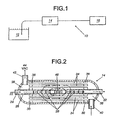
- Figure 1 is a schematic illustration of an ink debubbling system.
- Figure 2 is a schematic illustration of the first embodiment of a membrane contactor made according to the instant invention.
- Figure 3 is a schematic illustration of a second embodiment of the membrane contactor.
- Figure 4 is a schematic illustration of a third embodiment of the membrane contactor.
- Figure 5 is a graph illustrating the performance of the CELGARD SemiPer contactor to the instant invention.
-
- Referring to the drawings wherein like numerals indicate like elements, there is shown in Figure 1 an
ink debubbling system 10.Ink debubbling system 10 comprises anink reservoir 12. Amembrane contactor 14 is in fluid communication with thereservoir 12. Anend use application 16 is in fluid communication withmembrane contactor 14. End use application may be, but is not limited to, an ink jet printing head (thermal or piezoelectric), a ink cartridge filling station, or the like. - Ink, as used herein, is a fluid containing pigments or dyes. Inks, preferably, have a surface tension less than water at room temperature (i.e., about 72.75 dynes/cm at 20°C and 71.20 dynes/cm at 30°C). These inks are, preferably, used in computer printers or other ink jet type printers. Such inks, preferably, have a viscosity of 0.8 to 10 centipoises (CPS), a specific gravity of 0.7 to 1.5 grams per milliliter (g/ml), and a surface tension of 20 to 40 dynes per centimeter (dynes/cm).
- The
membrane contactor 14, which is discussed in greater detail below, is an external flow, hollow fiber membrane module. Hollow fiber membrane contactors are known. For example see: U.S. Patent Nos. 3,228,877; 3,755,034; 4,220,535; 4,940,617; 5,186,832; 5,264,171; 5,284,584; 5,449,457, each is incorporated herein by reference. Themembrane contactor 14 has a lumen side. and a shell side. The lumen side, also known as the internal side, is defined, in large part, by the lumen of the hollow fiber. The shell side, also known as the external side, is defined, in part, by the external surface of the hollow fiber. The ink travels through the shell (or external) side, while the vacuum (or vacuum and sweep gas) is applied to the lumen (or internal) side. Thereby, entrained gases from the ink pass from the shell side through the membrane to the lumen side. Thecontactor 14 is made of components that are inert to or non-reactive with the ink (or other liquid). Preferrably, these components are plastic, but metals may be used. - The membrane is preferably a semi-permeable, gas selective, heterogeneous, integrally asymmetric, and liquid impermeable membrane. The membrane has a permeability of less than 100 Barrers (10-8 standard cm3.cm/sec.cm2.cm(Hg)). The membrane preferably has an active surface area of 0.1 to 20 meters2. The membrane is, preferably, a skinned membrane and the skin is on the shell side. The membrane is, preferably, a single layer membrane (e.g., not a composite or multi-layered membrane) and is made from a homopolymer of polymethylpentene. For example, see U.S. Patent No. 4,664,681, incorporated herein by reference.
- Referring to Figure 2,
ink 22 enterscontactor 14 viaink inlet 24 ofcore tube 26.Core tube 26 includes a perforated 28 area immediately ahead of block 30.Ink 22 travels through theinlet 24 ofcore tube 26 andexits tube 26 viaperforations 28 when it is diverted by block 30.Ink 22 then travels over the exterior surfaces ofhollow fibers 34. Ink 22 re-enterscore tube 26 viaperforations 28 on the other side of block 30 andexits tube 26 viaink outlet 32. Thehollow fibers 34 surroundscore tube 26 and are maintained generally parallel totube 26's axis viatube sheets 36.Hollow fibers 34 extend throughtube sheet 36 and are in communication withheadspaces 38 on either end ofcontactor 14, so thatvacuum 44 drawn atports headspaces 38.Port 40, for example, may also be used to introduce a sweep gas, which facilitates entrained gas removal. - Referring to Figure 3, contactor 14' is the same as shown in Figure 2 but for a
flow diverting baffle 46 located within the shell side, andport 40 has been moved. Thebaffle 46 is added to promote distribution of ink over all exterior surfaces of thehollow fibers 34.Port 40 is moved to illustrate the non-criticality of port location. - Referring to Figure 4, contactor 14'' differs from
contactors 14 and 14' by movingink outlet 32 from the terminal end ofcore tube 26 to the contactor shell, as illustrated.Vacuum 44 is in communication withheadspace 38 which, in turn, is in communication with the lumens ofhollow fibers 34. The second headspace illustrated in the previous embodiments has been eliminated.Ink 22 entersink inlet 24 ofcore tube 26.Ink 22 exitstube 26 viaperforations 28, travels over the exterior surfaces ofhollow fibers 34, and exits the shell side viaoutlet 32.Outlet 32 may be placed at other locations on the exterior of the contactor so that it maintains communication with the shell side. - In operation, entrained gasses, which form bubbles, are removed from the ink by a concentration difference across the membrane, that is by diffusion. Vacuum, ranging from 25 to 200 torr, is placed on lumen side of the membrane, and the gas entrained ink is in contact with the shell side (or exterior surface) of the membrane. The concentration (partial pressure of the gas) difference drives the gas from the ink on the shell side, through the membrane to the lumen side. Furthermore, by routing the ink through the shell (or exterior) side, versus the lumen side, the pressure drop of the ink through the contactor is greatly reduced. This is because passage through the lumens provides a much greater resistance to flow than the shell side space. In Figure 5, the performance of a contactor according to the present invention is compared to CELGARD's SemiPer contactor. The graph illustrates 'Dissolved Oxygen (DO) Removal Efficiency' (%) as a function of water flow rate (liters/minute) at 20°C and 35 torr of vacuum. Water was used, instead of ink, but contactor performance is deemed analogous to the foregoing inks at the stated conditions. The upper curve represents performance of the instant invention (2.5" diameter), and the lower curve represents performace of the SemiPer contactor (2.5" diameter).
- The present invention may be embodied in other specific forms without departing from the spirit or essential attributes thereof, and, accordingly, reference should be made to the appended claims, rather than to the foregoing specification, as indicating the scope of the invention.
Claims (13)
- A method for debubbling an ink comprising the steps of:providing an ink having a gas entrained therein;providing a membrane contactor comprising a plurality of polymethyl pentene hollow fiber microporous membranes, the membrane defining within the contactor a lumen side and a shell side;providing a vacuum;passing the gas entrained ink through the shell side of the contactor;applying the vacuum to the lumen side of the contactor; anddebubbling the gas entrained ink across the membrane.
- The method of claim 1 wherein the ink has a surface tension less than the surface tension of water at room temperature.
- The method of claim 1 wherein the ink has a viscosity of 0.8 to 10 centipoises, a specific gravity of 0.7 to 1.5 grams per milliliter, and a surface tension of 20 to 40 dynes per centimeter.
- The method of claim 1 wherein the membrane contactor is an external flow, hollow fiber membrane module.
- The method of claim 1 wherein the membrane has an active surface area of 0.1 to 20 meters2.
- The method of claim 1 wherein the membrane has a permeability of less than 100 Barrers.
- The method of claim 1 wherein the membrane has a single layer.
- The method of claim 1 wherein the membrane is a semi-permeable, gas selective, heterogeneous, liquid impermeable membrane.
- The method of claim 1 wherein the membrane is a homopolymer of polymethylpentene.
- The method of claim 4 wherein the module includes a baffle.
- The method of claim 1 wherein the vacuum ranges from 25 to 200 torr.
- A method for debubbling an ink comprising the steps of:providing an ink having a gas entrained therein, the ink having a viscosity of 0.8 to 10 centipoises, a specific gravity of 0.7 to 1.5 grams per milliliter, and a surface tension of 20 to 40 dynes per centimeter;providing a membrane contactor comprising a plurality of integrally asymmetric, hollow fiber microporous membrane, the membrane defining within the contactor a lumen side and a shell side, the membrane having an active surface area of 0.1 to 20 meters2;providing a vacuum, the vacuum ranging from 25 to 200 torr;passing the gas entrained ink through the shell side of the contactor;applying the vacuum to the lumen side of the contactor; anddebubbling the gas entrained ink across the membrane.
- The method of claim 11 wherein the membrane is a homopolymer of polymethylpentene.
Applications Claiming Priority (2)
| Application Number | Priority Date | Filing Date | Title |
|---|---|---|---|
| US09/816,730 US6558450B2 (en) | 2001-03-22 | 2001-03-22 | Method for debubbling an ink |
| US816730 | 2001-03-22 |
Publications (3)
| Publication Number | Publication Date |
|---|---|
| EP1243310A2 true EP1243310A2 (en) | 2002-09-25 |
| EP1243310A3 EP1243310A3 (en) | 2003-02-12 |
| EP1243310B1 EP1243310B1 (en) | 2006-09-27 |
Family
ID=25221464
Family Applications (1)
| Application Number | Title | Priority Date | Filing Date |
|---|---|---|---|
| EP02004590A Expired - Lifetime EP1243310B1 (en) | 2001-03-22 | 2002-02-28 | Method for debubbling an ink |
Country Status (4)
| Country | Link |
|---|---|
| US (2) | US6558450B2 (en) |
| EP (1) | EP1243310B1 (en) |
| JP (2) | JP2002317131A (en) |
| DE (1) | DE60214921T2 (en) |
Cited By (11)
| Publication number | Priority date | Publication date | Assignee | Title |
|---|---|---|---|---|
| EP1683641A1 (en) * | 2004-12-28 | 2006-07-26 | Canon Kabushiki Kaisha | Liquid housing container and liquid supply apparatus |
| WO2007050174A1 (en) * | 2005-10-28 | 2007-05-03 | Hewlett-Packard Development Company, L.P. | Free flow fluid delivery system for printing device |
| WO2007063720A1 (en) | 2005-11-30 | 2007-06-07 | Konica Minolta Holdings, Inc. | Method for degassing of ink-jet ink, method for production of ink-jet ink, and ink-jet printer |
| EP2017615A1 (en) * | 2006-02-16 | 2009-01-21 | Arkray, Inc. | Degasifier and liquid chromatograph equipped therewith |
| US7490925B2 (en) | 2005-10-28 | 2009-02-17 | Hewlett-Packard Development Company, L.P. | Free flow fluid delivery system for printing device |
| CN102022158A (en) * | 2009-09-16 | 2011-04-20 | 通用汽车环球科技运作公司 | Membrane separation of water and fuel from engine oil in an internal combustion engine |
| EP2653935A1 (en) * | 2012-04-18 | 2013-10-23 | Miyakoshi Printing Machinery Co., Ltd. | Apparatus for detecting a toner density of a liquid developer |
| US20140111585A1 (en) * | 2012-10-23 | 2014-04-24 | Mimaki Engineering Co., Ltd. | Printer, ink supply device and printing method |
| EP3238943A4 (en) * | 2014-12-24 | 2018-08-01 | DIC Corporation | Hollow-fiber degassing module and inkjet printer |
| CN110354685A (en) * | 2019-06-14 | 2019-10-22 | 浙江启尔机电技术有限公司 | A kind of gas-liquid separation device for lithographic equipment |
| CN112516800A (en) * | 2020-10-30 | 2021-03-19 | 宁波方太厨具有限公司 | Hollow fiber membrane element and method for producing same |
Families Citing this family (45)
| Publication number | Priority date | Publication date | Assignee | Title |
|---|---|---|---|---|
| US6558450B2 (en) * | 2001-03-22 | 2003-05-06 | Celgard Inc. | Method for debubbling an ink |
| US6616841B2 (en) * | 2001-06-21 | 2003-09-09 | Celgard Inc. | Hollow fiber membrane contactor |
| US20040000232A1 (en) * | 2001-11-13 | 2004-01-01 | Van Horne William J. | Device and method for exchanging oxygen and carbon dioxide between a gas and an aqueous liquid |
| US7314502B2 (en) * | 2002-09-25 | 2008-01-01 | Exxonmobil Upstream Research Company | Method and system for separating a component from a multi-component gas |
| US6709492B1 (en) * | 2003-04-04 | 2004-03-23 | United Technologies Corporation | Planar membrane deoxygenator |
| US6939392B2 (en) * | 2003-04-04 | 2005-09-06 | United Technologies Corporation | System and method for thermal management |
| US7387661B2 (en) * | 2003-04-22 | 2008-06-17 | Entegris, Inc. | Pleated construction for effecting gas transfer membrane |
| US7779781B2 (en) * | 2003-07-31 | 2010-08-24 | Asml Netherlands B.V. | Lithographic apparatus and device manufacturing method |
| US7311761B2 (en) * | 2003-12-11 | 2007-12-25 | Seiko Epson Corporation | Gas absorption device, method of manufacturing the same, and liquid container |
| US7172696B1 (en) * | 2004-01-02 | 2007-02-06 | Spectrum Laboratories, Inc. | Radial dispersion mass transfer device having a semi-permeable tubular hollow fiber membrane wound around a porous core |
| US7052122B2 (en) * | 2004-02-19 | 2006-05-30 | Dimatix, Inc. | Printhead |
| US20050274649A1 (en) * | 2004-06-09 | 2005-12-15 | Spadaccini Louis J | Method for suppressing oxidative coke formation in liquid hydrocarbons containing metal |
| WO2006064036A1 (en) * | 2004-12-17 | 2006-06-22 | Agfa Graphics Nv | Ink circulation system for inkjet printing |
| US7393388B2 (en) * | 2005-05-13 | 2008-07-01 | United Technologies Corporation | Spiral wound fuel stabilization unit for fuel de-oxygenation |
| US7435283B2 (en) * | 2005-05-18 | 2008-10-14 | United Technologies Corporation | Modular fuel stabilization system |
| US7465336B2 (en) * | 2005-06-09 | 2008-12-16 | United Technologies Corporation | Fuel deoxygenation system with non-planar plate members |
| US7377112B2 (en) | 2005-06-22 | 2008-05-27 | United Technologies Corporation | Fuel deoxygenation for improved combustion performance |
| US7427312B2 (en) * | 2005-07-13 | 2008-09-23 | Rheodyne, Llc | Integrated degassing and debubbling apparatus |
| CN101500692B (en) * | 2005-07-13 | 2012-05-23 | 雷奥戴纳有限公司 | Integrated degassing and debubbling apparatus |
| US20070101731A1 (en) * | 2005-09-07 | 2007-05-10 | United Technologies Corporation | Deoxygenated fuel-cooled environmental control system pre-cooler for an aircraft |
| US7717983B2 (en) * | 2005-10-18 | 2010-05-18 | Parker-Hannifin Corporation | Air separation module with load carrying center tube |
| US7615104B2 (en) | 2005-11-03 | 2009-11-10 | United Technologies Corporation | Fuel deoxygenation system with multi-layer oxygen permeable membrane |
| WO2007060866A1 (en) * | 2005-11-22 | 2007-05-31 | Nec Corporation | Gas-liquid separator and liquid feed fuel cell |
| US20070130956A1 (en) * | 2005-12-08 | 2007-06-14 | Chen Alexander G | Rich catalytic clean burn for liquid fuel with fuel stabilization unit |
| US7824470B2 (en) * | 2006-01-18 | 2010-11-02 | United Technologies Corporation | Method for enhancing mass transport in fuel deoxygenation systems |
| US7569099B2 (en) * | 2006-01-18 | 2009-08-04 | United Technologies Corporation | Fuel deoxygenation system with non-metallic fuel plate assembly |
| US7582137B2 (en) * | 2006-01-18 | 2009-09-01 | United Technologies Corporation | Fuel deoxygenator with non-planar fuel channel and oxygen permeable membrane |
| JP4492581B2 (en) * | 2006-04-20 | 2010-06-30 | カシオ計算機株式会社 | Humidifier, power generator and method for manufacturing hollow fiber membrane module |
| US7682421B2 (en) * | 2006-10-12 | 2010-03-23 | Celgard Llc | Degassing a liquid using a gravity fed apparatus |
| US8066801B2 (en) * | 2007-04-24 | 2011-11-29 | New York Air Brake Corporation | Sweep air system for membrane air dryer |
| JP2010076413A (en) * | 2007-12-11 | 2010-04-08 | Seiko Epson Corp | Liquid supply device and liquid jetting apparatus |
| KR101465295B1 (en) | 2008-05-30 | 2014-11-26 | 디아이씨 가부시끼가이샤 | Process for manufacturing deaerating hollow fiber module |
| GB2474192A (en) * | 2008-10-20 | 2011-04-06 | Agilent Technologies Inc | Degasser with vent in vacuum chamber |
| GB2477679A (en) * | 2008-10-30 | 2011-08-10 | Porous Media Corp | Venting and filtration systems with gas permeable membrane |
| JP5195473B2 (en) * | 2009-02-04 | 2013-05-08 | セイコーエプソン株式会社 | Liquid absorption tank and liquid droplet ejection apparatus provided with the same |
| CH701558A2 (en) * | 2009-07-31 | 2011-01-31 | Alex Knobel | Device and method for mixing and exchange of fluids. |
| US20110274795A1 (en) * | 2010-05-05 | 2011-11-10 | Monosol Rx, Llc | In-line deaeration process for the production of self-supporting film products |
| US20120234171A1 (en) * | 2011-03-19 | 2012-09-20 | Charles Solomon | System for degassing a liquid |
| US9623369B2 (en) * | 2011-06-08 | 2017-04-18 | Porogen Corporation | Hollow fiber apparatus and use thereof for fluids separations and heat and mass transfers |
| FR3003564B1 (en) | 2013-03-19 | 2015-03-06 | Arkema France | METATHESIS METHOD COMPRISING THE EXTRACTION OF ETHYLENE FORMED USING A MEMBRANE |
| JP6098264B2 (en) | 2013-03-21 | 2017-03-22 | セイコーエプソン株式会社 | Recording device |
| KR102029878B1 (en) * | 2014-12-24 | 2019-10-08 | 디아이씨 가부시끼가이샤 | Hollow-fiber degassing module and inkjet printer |
| WO2017195818A1 (en) * | 2016-05-11 | 2017-11-16 | 三菱ケミカル・クリンスイ株式会社 | Hollow fiber membrane module |
| JP2018144430A (en) * | 2017-03-08 | 2018-09-20 | セイコーエプソン株式会社 | Inkjet method and ink jet device |
| JP6788014B2 (en) * | 2017-06-14 | 2020-11-18 | 三菱ケミカル・クリンスイ株式会社 | External perfusion type hollow fiber membrane module |
Citations (5)
| Publication number | Priority date | Publication date | Assignee | Title |
|---|---|---|---|---|
| WO1999032186A1 (en) * | 1997-12-22 | 1999-07-01 | Celgard, Llc | Device for removal of gas bubbles and dissolved gasses in liquid |
| US5938922A (en) * | 1997-08-19 | 1999-08-17 | Celgard Llc | Contactor for degassing liquids |
| EP1033162A1 (en) * | 1997-10-02 | 2000-09-06 | Mitsubishi Rayon Co., Ltd. | Composite hollow fiber membrane |
| EP1052011A1 (en) * | 1997-04-30 | 2000-11-15 | Mitsubishi Rayon Co., Ltd. | Ink deaerating hollow yarn membrane, ink deaerating method, ink deaerating apparatus, ink cartridge manufacturing method, and ink |
| EP1160002A2 (en) * | 2000-06-02 | 2001-12-05 | Celgard, Inc. | Degassing a liquid with a membrane contactor |
Family Cites Families (44)
| Publication number | Priority date | Publication date | Assignee | Title |
|---|---|---|---|---|
| BE608328A (en) | 1960-09-19 | |||
| GB1366615A (en) | 1971-02-25 | 1974-09-11 | Dow Chemical Co | Method for making a hollow fibre separatory element |
| US4220535A (en) | 1978-08-04 | 1980-09-02 | Monsanto Company | Multi-zoned hollow fiber permeator |
| JPS58219067A (en) * | 1982-06-14 | 1983-12-20 | Ricoh Co Ltd | Ink-supplying device for ink jet printer |
| US4421529A (en) * | 1982-07-02 | 1983-12-20 | The Dow Chemical Company | Membrane system for intermittent gas separation |
| JPS59196706A (en) | 1983-04-22 | 1984-11-08 | Dainippon Ink & Chem Inc | Heterogenous membrane and preparation thereof |
| US4752305A (en) * | 1986-10-30 | 1988-06-21 | The Dow Chemical Company | Device and method for separating individual fluids from a mixture of fluids |
| US4707267A (en) * | 1987-01-22 | 1987-11-17 | The Dow Chemical Company | Device and method for separating individual fluids from a mixture of fluids |
| DE3803693A1 (en) | 1987-03-10 | 1988-09-22 | Akzo Gmbh | MULTI-LAYER HOLLOW FILM BODY |
| US4788556A (en) * | 1987-04-28 | 1988-11-29 | Spectra, Inc. | Deaeration of ink in an ink jet system |
| JP2725311B2 (en) * | 1988-10-13 | 1998-03-11 | 大日本インキ化学工業株式会社 | Hollow fiber membrane type gas-liquid contactor |
| JP2725312B2 (en) * | 1988-10-14 | 1998-03-11 | 大日本インキ化学工業株式会社 | Porous hollow fiber membrane type gas-liquid contactor |
| JPH02135117A (en) * | 1988-11-16 | 1990-05-24 | Sumitomo Heavy Ind Ltd | Gas separation module and multistage gas separator |
| US4869732A (en) * | 1988-12-23 | 1989-09-26 | Texaco Inc. | Deoxygenation of aqueous polymer solutions used in enhanced oil recovery processes |
| JP2780331B2 (en) * | 1989-04-28 | 1998-07-30 | 日東電工株式会社 | Liquid degassing method |
| JPH0380983A (en) * | 1989-08-24 | 1991-04-05 | Dainippon Ink & Chem Inc | Gas-liquid contact type water purifying apparatus and method |
| JP2949732B2 (en) * | 1989-09-26 | 1999-09-20 | 大日本インキ化学工業株式会社 | Degassing method using pervaporation membrane module |
| JPH03118802A (en) * | 1989-10-02 | 1991-05-21 | Dainippon Ink & Chem Inc | Deoxidizing device |
| JP2954652B2 (en) * | 1990-04-24 | 1999-09-27 | 日東電工株式会社 | Removal method of gas or low boiling volatile organic matter |
| US5254143A (en) * | 1990-07-09 | 1993-10-19 | Dainippon Ink And Chemical, Inc. | Diaphragm for gas-liquid contact, gas-liquid contact apparatus and process for producing liquid containing gas dissolved therein |
| US5449457A (en) | 1991-04-22 | 1995-09-12 | Hoechst Celanese Corporation | Liquid membrane modules with minimal effective membrane thickness and methods of making the same |
| JPH0517712A (en) | 1991-07-08 | 1993-01-26 | Seiko Epson Corp | Deaeration of ink for ink-jet recording |
| US5211728A (en) * | 1991-09-30 | 1993-05-18 | The Dow Chemical Company | Clamshell retainer used in hollow fiber membrane devices |
| US5264171A (en) | 1991-12-31 | 1993-11-23 | Hoechst Celanese Corporation | Method of making spiral-wound hollow fiber membrane fabric cartridges and modules having flow-directing baffles |
| US5186832A (en) | 1991-12-31 | 1993-02-16 | Hoechst Celanese Corporation | Spiral-wound hollow fiber membrane fabric cartridges and modules having integral turbulence promoters |
| JPH06134446A (en) * | 1992-10-27 | 1994-05-17 | Dainippon Ink & Chem Inc | Method for manufacturing deaerated water and module for manufacture of deaerated water |
| US5284584A (en) | 1992-12-31 | 1994-02-08 | Hoechst Celanese Corporation | Hollow fiber membrane fabric - containing cartridges and modules having solvent-resistant thermoplastic tube sheets, and methods for making the same |
| JPH06327905A (en) * | 1993-05-21 | 1994-11-29 | Toray Ind Inc | Degassing membrane module and its operation |
| JPH0760005A (en) * | 1993-08-31 | 1995-03-07 | Miura Co Ltd | Dearation of liquid product |
| US5659346A (en) * | 1994-03-21 | 1997-08-19 | Spectra, Inc. | Simplified ink jet head |
| JPH0994447A (en) * | 1995-09-29 | 1997-04-08 | Dainippon Ink & Chem Inc | Liquid chemical feeder and method for degassing liquid chemical |
| US5695545A (en) * | 1996-05-10 | 1997-12-09 | Hoechst Celanese Corporation | Degassing liquids: apparatus and method |
| JPH1060339A (en) | 1996-08-23 | 1998-03-03 | Ricoh Co Ltd | Ink degassing equipment and ink degassing method |
| JPH11209670A (en) * | 1998-01-28 | 1999-08-03 | Mitsubishi Rayon Co Ltd | Ink for ink jet printer, method for removing dissolved gas from ink for ink jet printer, and production of ink cartridge for ink jet printer |
| JPH10298470A (en) | 1997-04-30 | 1998-11-10 | Mitsubishi Rayon Co Ltd | Method and apparatus for deaerating ink |
| US5808643A (en) | 1997-06-30 | 1998-09-15 | Xerox Corporation | Air removal means for ink jet printers |
| EP0894631B1 (en) | 1997-08-01 | 2004-02-25 | Seiko Epson Corporation | Ink-jet recording apparatus |
| JPH11179167A (en) * | 1997-12-25 | 1999-07-06 | Nitto Denko Corp | Spiral type membrane module |
| JP4026037B2 (en) * | 1998-09-10 | 2007-12-26 | 大日本インキ化学工業株式会社 | Hollow fiber membrane gas-liquid gas exchange device and gas exchange method thereof |
| JP2000288369A (en) * | 1999-04-01 | 2000-10-17 | Mitsubishi Rayon Co Ltd | Gas separation membrane |
| JP4550216B2 (en) * | 1999-04-02 | 2010-09-22 | 三菱レイヨン株式会社 | Hollow fiber membrane module, potting material thereof and method for degassing chemical solution |
| JP2000318184A (en) * | 1999-05-11 | 2000-11-21 | Canon Inc | Ink jet recording apparatus and color filter producing apparatus having the same |
| JP2000317210A (en) * | 1999-05-13 | 2000-11-21 | Mitsubishi Rayon Co Ltd | Device and method for degassing liquid chemical |
| US6558450B2 (en) * | 2001-03-22 | 2003-05-06 | Celgard Inc. | Method for debubbling an ink |
-
2001
- 2001-03-22 US US09/816,730 patent/US6558450B2/en not_active Expired - Lifetime
-
2002
- 2002-02-28 EP EP02004590A patent/EP1243310B1/en not_active Expired - Lifetime
- 2002-02-28 DE DE60214921T patent/DE60214921T2/en not_active Expired - Lifetime
- 2002-03-07 JP JP2002061342A patent/JP2002317131A/en active Pending
-
2003
- 2003-02-12 US US10/364,873 patent/US6790262B2/en not_active Expired - Lifetime
-
2005
- 2005-04-12 JP JP2005114615A patent/JP2005305432A/en active Pending
Patent Citations (5)
| Publication number | Priority date | Publication date | Assignee | Title |
|---|---|---|---|---|
| EP1052011A1 (en) * | 1997-04-30 | 2000-11-15 | Mitsubishi Rayon Co., Ltd. | Ink deaerating hollow yarn membrane, ink deaerating method, ink deaerating apparatus, ink cartridge manufacturing method, and ink |
| US5938922A (en) * | 1997-08-19 | 1999-08-17 | Celgard Llc | Contactor for degassing liquids |
| EP1033162A1 (en) * | 1997-10-02 | 2000-09-06 | Mitsubishi Rayon Co., Ltd. | Composite hollow fiber membrane |
| WO1999032186A1 (en) * | 1997-12-22 | 1999-07-01 | Celgard, Llc | Device for removal of gas bubbles and dissolved gasses in liquid |
| EP1160002A2 (en) * | 2000-06-02 | 2001-12-05 | Celgard, Inc. | Degassing a liquid with a membrane contactor |
Non-Patent Citations (1)
| Title |
|---|
| PATENT ABSTRACTS OF JAPAN vol. 1995, no. 02, 31 March 1995 (1995-03-31) -& JP 06 327905 A (TORAY IND INC), 29 November 1994 (1994-11-29) -& DATABASE WPI Section Ch, Week 199507 Derwent Publications Ltd., London, GB; Class A18, AN 1995-048002 XP002225283 & JP 06 327905 A (TORAY IND INC), 29 November 1994 (1994-11-29) * |
Cited By (21)
| Publication number | Priority date | Publication date | Assignee | Title |
|---|---|---|---|---|
| US7473302B2 (en) | 2004-12-28 | 2009-01-06 | Canon Kabushiki Kaisha | Liquid housing container and liquid supply apparatus |
| EP1683641A1 (en) * | 2004-12-28 | 2006-07-26 | Canon Kabushiki Kaisha | Liquid housing container and liquid supply apparatus |
| WO2007050174A1 (en) * | 2005-10-28 | 2007-05-03 | Hewlett-Packard Development Company, L.P. | Free flow fluid delivery system for printing device |
| US7490925B2 (en) | 2005-10-28 | 2009-02-17 | Hewlett-Packard Development Company, L.P. | Free flow fluid delivery system for printing device |
| US7500737B2 (en) | 2005-10-28 | 2009-03-10 | Hewlett-Packard Development Company, L.P. | Free flow fluid delivery system for printing device |
| US8205977B2 (en) | 2005-11-30 | 2012-06-26 | Konica Minolta Holdings, Inc. | Degassing method of ink-jet ink, production method of ink-jet ink and ink-jet printer |
| WO2007063720A1 (en) | 2005-11-30 | 2007-06-07 | Konica Minolta Holdings, Inc. | Method for degassing of ink-jet ink, method for production of ink-jet ink, and ink-jet printer |
| EP1967559A1 (en) * | 2005-11-30 | 2008-09-10 | Konica Minolta Holdings, Inc. | Method for degassing of ink-jet ink, method for production of ink-jet ink, and ink-jet printer |
| EP1967559A4 (en) * | 2005-11-30 | 2010-11-03 | Konica Minolta Holdings Inc | Method for degassing of ink-jet ink, method for production of ink-jet ink, and ink-jet printer |
| EP2017615A1 (en) * | 2006-02-16 | 2009-01-21 | Arkray, Inc. | Degasifier and liquid chromatograph equipped therewith |
| EP2017615A4 (en) * | 2006-02-16 | 2009-07-29 | Arkray Inc | Degasifier and liquid chromatograph equipped therewith |
| CN102022158A (en) * | 2009-09-16 | 2011-04-20 | 通用汽车环球科技运作公司 | Membrane separation of water and fuel from engine oil in an internal combustion engine |
| CN102022158B (en) * | 2009-09-16 | 2013-11-27 | 通用汽车环球科技运作公司 | Membrane separation of water and fuel from engine oil in internal combustion engine |
| EP2653935A1 (en) * | 2012-04-18 | 2013-10-23 | Miyakoshi Printing Machinery Co., Ltd. | Apparatus for detecting a toner density of a liquid developer |
| US9329524B2 (en) | 2012-04-18 | 2016-05-03 | Miyakoshi Printing Machinery Co., Ltd. | Apparatus for detecting a toner density of a liquid developer |
| US20140111585A1 (en) * | 2012-10-23 | 2014-04-24 | Mimaki Engineering Co., Ltd. | Printer, ink supply device and printing method |
| US9713925B2 (en) * | 2012-10-23 | 2017-07-25 | Mimaki Engineering Co., Ltd. | Printer, ink supply device and printing method |
| EP3238943A4 (en) * | 2014-12-24 | 2018-08-01 | DIC Corporation | Hollow-fiber degassing module and inkjet printer |
| CN110354685A (en) * | 2019-06-14 | 2019-10-22 | 浙江启尔机电技术有限公司 | A kind of gas-liquid separation device for lithographic equipment |
| CN112516800A (en) * | 2020-10-30 | 2021-03-19 | 宁波方太厨具有限公司 | Hollow fiber membrane element and method for producing same |
| CN112516800B (en) * | 2020-10-30 | 2022-02-08 | 宁波方太厨具有限公司 | Method for manufacturing hollow fiber membrane element |
Also Published As
| Publication number | Publication date |
|---|---|
| JP2002317131A (en) | 2002-10-31 |
| EP1243310B1 (en) | 2006-09-27 |
| JP2005305432A (en) | 2005-11-04 |
| DE60214921T2 (en) | 2007-06-06 |
| US6790262B2 (en) | 2004-09-14 |
| US20030116015A1 (en) | 2003-06-26 |
| EP1243310A3 (en) | 2003-02-12 |
| US6558450B2 (en) | 2003-05-06 |
| US20020134235A1 (en) | 2002-09-26 |
| DE60214921D1 (en) | 2006-11-09 |
Similar Documents
| Publication | Publication Date | Title |
|---|---|---|
| US6558450B2 (en) | Method for debubbling an ink | |
| US6447679B1 (en) | Hollow fiber membrane | |
| JP5869038B2 (en) | Degassing liquid with membrane contactor | |
| EP0448973B1 (en) | Spiral wound gas permeable membrane module and apparatus and method for using the same | |
| US6168648B1 (en) | Spiral wound type membrane module, spiral wound type membrane element and running method thereof | |
| KR100355180B1 (en) | Degassing and Treatment Equipment | |
| EP1485193B1 (en) | Hollow fiber membrane contact apparatus and process | |
| US4151088A (en) | Membrane diffusion device with integral heat exchanger and reservoir | |
| JPH07136251A (en) | Gas exchanging device especially for oxygenation to blood | |
| JP5080781B2 (en) | Hollow fiber membrane module for degassing and degassing device | |
| JP2512937B2 (en) | Membrane type gas-liquid contactor | |
| JP2000084368A (en) | Multiple hollow fiber membrane for liquid chemical deaeration | |
| JPH10298470A (en) | Method and apparatus for deaerating ink | |
| JPH11209670A (en) | Ink for ink jet printer, method for removing dissolved gas from ink for ink jet printer, and production of ink cartridge for ink jet printer | |
| JP2002370006A (en) | Liquid treatment apparatus and treatment method using the same | |
| US6328785B1 (en) | Method of degassing aqueous coating solution | |
| JP2000288366A (en) | Composite plane membrane | |
| JP2002113334A (en) | Hollow fiber membrane module and method for treating liquid using the same | |
| JPH059042Y2 (en) | ||
| JP7458605B1 (en) | Plasma exchange system and control method for plasma exchange system | |
| JPH11188202A (en) | Deaeration of photosensitive coating liquid | |
| JP2002168765A (en) | Inspection method and inspection device of liquid | |
| MXPA99010029A (en) | Ink deaerating hollow yarn membrane, ink deaerating method, ink deaerating apparatus, ink cartridge manufacturing method, and ink |
Legal Events
| Date | Code | Title | Description |
|---|---|---|---|
| PUAI | Public reference made under article 153(3) epc to a published international application that has entered the european phase |
Free format text: ORIGINAL CODE: 0009012 |
|
| AK | Designated contracting states |
Kind code of ref document: A2 Designated state(s): AT BE CH CY DE DK ES FI FR GB GR IE IT LI LU MC NL PT SE TR |
|
| AX | Request for extension of the european patent |
Free format text: AL;LT;LV;MK;RO;SI |
|
| PUAL | Search report despatched |
Free format text: ORIGINAL CODE: 0009013 |
|
| RIC1 | Information provided on ipc code assigned before grant |
Ipc: 7B 01D 19/00 B Ipc: 7B 01D 61/00 A |
|
| AK | Designated contracting states |
Designated state(s): AT BE CH CY DE DK ES FI FR GB GR IE IT LI LU MC NL PT SE TR |
|
| AX | Request for extension of the european patent |
Extension state: AL LT LV MK RO SI |
|
| 17P | Request for examination filed |
Effective date: 20030514 |
|
| AKX | Designation fees paid |
Designated state(s): DE FR GB IT |
|
| 17Q | First examination report despatched |
Effective date: 20040211 |
|
| GRAP | Despatch of communication of intention to grant a patent |
Free format text: ORIGINAL CODE: EPIDOSNIGR1 |
|
| GRAS | Grant fee paid |
Free format text: ORIGINAL CODE: EPIDOSNIGR3 |
|
| GRAA | (expected) grant |
Free format text: ORIGINAL CODE: 0009210 |
|
| AK | Designated contracting states |
Kind code of ref document: B1 Designated state(s): DE FR GB IT |
|
| PG25 | Lapsed in a contracting state [announced via postgrant information from national office to epo] |
Ref country code: IT Free format text: LAPSE BECAUSE OF FAILURE TO SUBMIT A TRANSLATION OF THE DESCRIPTION OR TO PAY THE FEE WITHIN THE PRESCRIBED TIME-LIMIT;WARNING: LAPSES OF ITALIAN PATENTS WITH EFFECTIVE DATE BEFORE 2007 MAY HAVE OCCURRED AT ANY TIME BEFORE 2007. THE CORRECT EFFECTIVE DATE MAY BE DIFFERENT FROM THE ONE RECORDED. Effective date: 20060927 |
|
| REG | Reference to a national code |
Ref country code: GB Ref legal event code: FG4D |
|
| REF | Corresponds to: |
Ref document number: 60214921 Country of ref document: DE Date of ref document: 20061109 Kind code of ref document: P |
|
| ET | Fr: translation filed | ||
| PLBE | No opposition filed within time limit |
Free format text: ORIGINAL CODE: 0009261 |
|
| STAA | Information on the status of an ep patent application or granted ep patent |
Free format text: STATUS: NO OPPOSITION FILED WITHIN TIME LIMIT |
|
| 26N | No opposition filed |
Effective date: 20070628 |
|
| REG | Reference to a national code |
Ref country code: FR Ref legal event code: PLFP Year of fee payment: 14 |
|
| REG | Reference to a national code |
Ref country code: DE Ref legal event code: R082 Ref document number: 60214921 Country of ref document: DE Representative=s name: VON KREISLER SELTING WERNER - PARTNERSCHAFT VO, DE Ref country code: DE Ref legal event code: R081 Ref document number: 60214921 Country of ref document: DE Owner name: CELGARD, LLC (N.D.GES.DES STAATES DELAWARE), C, US Free format text: FORMER OWNER: CELGARD INC., CHARLOTTE, N.C., US Ref country code: DE Ref legal event code: R081 Ref document number: 60214921 Country of ref document: DE Owner name: 3M INNOVATIVE PROPERTIES COMPANY, ST. PAUL, US Free format text: FORMER OWNER: CELGARD INC., CHARLOTTE, N.C., US Ref country code: DE Ref legal event code: R082 Ref document number: 60214921 Country of ref document: DE Representative=s name: DOMPATENT VON KREISLER SELTING WERNER - PARTNE, DE Ref country code: DE Ref legal event code: R082 Ref document number: 60214921 Country of ref document: DE Representative=s name: HETTSTEDT, STEPHAN, DR., DE |
|
| REG | Reference to a national code |
Ref country code: FR Ref legal event code: CD Owner name: CELGARD, LLC Effective date: 20151130 |
|
| REG | Reference to a national code |
Ref country code: FR Ref legal event code: PLFP Year of fee payment: 15 |
|
| REG | Reference to a national code |
Ref country code: GB Ref legal event code: 732E Free format text: REGISTERED BETWEEN 20160104 AND 20160106 |
|
| REG | Reference to a national code |
Ref country code: DE Ref legal event code: R082 Ref document number: 60214921 Country of ref document: DE Representative=s name: VON KREISLER SELTING WERNER - PARTNERSCHAFT VO, DE Ref country code: DE Ref legal event code: R081 Ref document number: 60214921 Country of ref document: DE Owner name: 3M INNOVATIVE PROPERTIES COMPANY, ST. PAUL, US Free format text: FORMER OWNER: CELGARD, LLC (N.D.GES.DES STAATES DELAWARE), CHARLOTTE, N.C., US Ref country code: DE Ref legal event code: R082 Ref document number: 60214921 Country of ref document: DE Representative=s name: DOMPATENT VON KREISLER SELTING WERNER - PARTNE, DE Ref country code: DE Ref legal event code: R082 Ref document number: 60214921 Country of ref document: DE Representative=s name: HETTSTEDT, STEPHAN, DR., DE |
|
| PGFP | Annual fee paid to national office [announced via postgrant information from national office to epo] |
Ref country code: FR Payment date: 20160108 Year of fee payment: 15 Ref country code: GB Payment date: 20160224 Year of fee payment: 15 |
|
| REG | Reference to a national code |
Ref country code: FR Ref legal event code: TP Owner name: 3M INNOVATIVE PROPERTIES COMPANY, US Effective date: 20160715 |
|
| GBPC | Gb: european patent ceased through non-payment of renewal fee |
Effective date: 20170228 |
|
| REG | Reference to a national code |
Ref country code: FR Ref legal event code: ST Effective date: 20171031 |
|
| PG25 | Lapsed in a contracting state [announced via postgrant information from national office to epo] |
Ref country code: FR Free format text: LAPSE BECAUSE OF NON-PAYMENT OF DUE FEES Effective date: 20170228 |
|
| PG25 | Lapsed in a contracting state [announced via postgrant information from national office to epo] |
Ref country code: GB Free format text: LAPSE BECAUSE OF NON-PAYMENT OF DUE FEES Effective date: 20170228 |
|
| REG | Reference to a national code |
Ref country code: DE Ref legal event code: R082 Ref document number: 60214921 Country of ref document: DE Representative=s name: HETTSTEDT, STEPHAN, DR., DE |
|
| PGFP | Annual fee paid to national office [announced via postgrant information from national office to epo] |
Ref country code: DE Payment date: 20190212 Year of fee payment: 18 |
|
| REG | Reference to a national code |
Ref country code: DE Ref legal event code: R119 Ref document number: 60214921 Country of ref document: DE |
|
| PG25 | Lapsed in a contracting state [announced via postgrant information from national office to epo] |
Ref country code: DE Free format text: LAPSE BECAUSE OF NON-PAYMENT OF DUE FEES Effective date: 20200901 |
|
| PGFP | Annual fee paid to national office [announced via postgrant information from national office to epo] |
Ref country code: IT Payment date: 20210112 Year of fee payment: 20 |