EP1243947A2 - Diffractive optical element, illumination system and exposure system and method - Google Patents
Diffractive optical element, illumination system and exposure system and method Download PDFInfo
- Publication number
- EP1243947A2 EP1243947A2 EP02006299A EP02006299A EP1243947A2 EP 1243947 A2 EP1243947 A2 EP 1243947A2 EP 02006299 A EP02006299 A EP 02006299A EP 02006299 A EP02006299 A EP 02006299A EP 1243947 A2 EP1243947 A2 EP 1243947A2
- Authority
- EP
- European Patent Office
- Prior art keywords
- surface wave
- radiation
- substrate
- waves
- source
- Prior art date
- Legal status (The legal status is an assumption and is not a legal conclusion. Google has not performed a legal analysis and makes no representation as to the accuracy of the status listed.)
- Granted
Links
Images


Classifications
-
- G—PHYSICS
- G03—PHOTOGRAPHY; CINEMATOGRAPHY; ANALOGOUS TECHNIQUES USING WAVES OTHER THAN OPTICAL WAVES; ELECTROGRAPHY; HOLOGRAPHY
- G03F—PHOTOMECHANICAL PRODUCTION OF TEXTURED OR PATTERNED SURFACES, e.g. FOR PRINTING, FOR PROCESSING OF SEMICONDUCTOR DEVICES; MATERIALS THEREFOR; ORIGINALS THEREFOR; APPARATUS SPECIALLY ADAPTED THEREFOR
- G03F7/00—Photomechanical, e.g. photolithographic, production of textured or patterned surfaces, e.g. printing surfaces; Materials therefor, e.g. comprising photoresists; Apparatus specially adapted therefor
- G03F7/70—Microphotolithographic exposure; Apparatus therefor
- G03F7/70058—Mask illumination systems
- G03F7/7015—Details of optical elements
- G03F7/70158—Diffractive optical elements
-
- G—PHYSICS
- G02—OPTICS
- G02B—OPTICAL ELEMENTS, SYSTEMS OR APPARATUS
- G02B5/00—Optical elements other than lenses
- G02B5/18—Diffraction gratings
-
- G—PHYSICS
- G02—OPTICS
- G02F—OPTICAL DEVICES OR ARRANGEMENTS FOR THE CONTROL OF LIGHT BY MODIFICATION OF THE OPTICAL PROPERTIES OF THE MEDIA OF THE ELEMENTS INVOLVED THEREIN; NON-LINEAR OPTICS; FREQUENCY-CHANGING OF LIGHT; OPTICAL LOGIC ELEMENTS; OPTICAL ANALOGUE/DIGITAL CONVERTERS
- G02F1/00—Devices or arrangements for the control of the intensity, colour, phase, polarisation or direction of light arriving from an independent light source, e.g. switching, gating or modulating; Non-linear optics
- G02F1/29—Devices or arrangements for the control of the intensity, colour, phase, polarisation or direction of light arriving from an independent light source, e.g. switching, gating or modulating; Non-linear optics for the control of the position or the direction of light beams, i.e. deflection
- G02F1/33—Acousto-optical deflection devices
-
- G—PHYSICS
- G03—PHOTOGRAPHY; CINEMATOGRAPHY; ANALOGOUS TECHNIQUES USING WAVES OTHER THAN OPTICAL WAVES; ELECTROGRAPHY; HOLOGRAPHY
- G03F—PHOTOMECHANICAL PRODUCTION OF TEXTURED OR PATTERNED SURFACES, e.g. FOR PRINTING, FOR PROCESSING OF SEMICONDUCTOR DEVICES; MATERIALS THEREFOR; ORIGINALS THEREFOR; APPARATUS SPECIALLY ADAPTED THEREFOR
- G03F7/00—Photomechanical, e.g. photolithographic, production of textured or patterned surfaces, e.g. printing surfaces; Materials therefor, e.g. comprising photoresists; Apparatus specially adapted therefor
- G03F7/70—Microphotolithographic exposure; Apparatus therefor
- G03F7/70216—Mask projection systems
- G03F7/70316—Details of optical elements, e.g. of Bragg reflectors, extreme ultraviolet [EUV] multilayer or bilayer mirrors or diffractive optical elements
Definitions
- the invention relates to an optical diffraction component for Provision of a radiation diffractive grating structure, the lattice structure for diffraction and deflection of a incident light beam by surface waves on a Surface of a substrate can be provided.
- One wavelength of the light to be diffracted at the grating structure first any wavelength from the optical spectrum his.
- the invention relates to one Diffractive optical component for providing a grating structure for diffraction of light in the areas of the ultraviolet, of extreme ultraviolet (EUV), with wavelengths of about 0.1nm to about 100nm, as well as the X-ray range.
- EUV extreme ultraviolet
- the invention further relates to a lighting system which is a light beam, especially from the wavelength ranges Ultraviolet, extreme ultraviolet and x-ray, is distractible and controllable.
- the invention further relates to an exposure system for imaging a provided on a mask Patterns on a substrate, one for illustration used light beam through the diffraction optical Component is controllable and the pattern in particular Components of a miniaturized device.
- the invention further relates to an exposure method for Production of a miniaturized component with one photolithographic step.
- miniaturized components in particular of semiconductor devices, is traditionally a photolithographic step used to get on a Mask predetermined structures onto one with a radiation sensitive Imaging layered substrate and thereby to expose the radiation sensitive layer.
- a lower one Limit of dimensions of the structures shown (CD, "critical dimension") is due to the wavelength of the for given the image used light.
- Components With always smaller structures of the miniaturized to be manufactured Components are therefore always shorter wavelengths of the Use light for illustration.
- wavelengths below ultraviolet imaging optical components and components for beam guidance or deflection are difficult to handle or technologies for such components not yet sufficiently developed. Examples of lighting optics in the The range of the EUV are from US 5 973 826, 6 033 079 and US 6 142 641 known.
- an optical diffraction Component for providing a radiation diffractive
- the invention provides a diffractive optical component a radiation diffractive lattice structure with a high Propose diffraction efficiency at short optical wavelengths.
- Another object of the invention is an exposure system to propose which is comparatively the figure small pattern.
- Another object of the invention is a method to propose for the manufacture of a component which especially for the production of components with small Structures is suitable.
- the invention is based on an optical diffraction component to provide a radiation diffractive grating structure, which comprises a surface acoustic wave device assembly comprising a Substrate, a surface wave source for generating Surface waves on a surface of the substrate and has an interaction area of the substrate surface, for an interaction of the radiation with a lattice structure is provided, which is generated by the surface waves is provided.
- a radiation diffractive grating structure which comprises a surface acoustic wave device assembly comprising a Substrate, a surface wave source for generating Surface waves on a surface of the substrate and has an interaction area of the substrate surface, for an interaction of the radiation with a lattice structure is provided, which is generated by the surface waves is provided.
- the invention lies in a first aspect of the knowledge based on the fact that the SAW lattice structure then has a high Diffraction efficiency can be provided if the SAW grating structure a high quality diffraction grating generated, which ideally by wave trains of surface waves is formed, whose profiles in the entire interaction area same, preferably essentially sinusoidal or have a sinusoidal shape.
- the surface wave source the conventional diffractive optical component in addition to surface waves, which emits towards the interaction area are also emitted surface waves that are not to the Interaction area are directed. This actually from surface waves directed away from the interaction area are reflected at the edges of the substrate and eventually reach the Interaction area where they get the profiles of the directly from the Surface wave source towards the interaction area emitted surface waves and ultimately interfere lower the quality of the optical grating.
- the invention is the idea underlying surface waves that are not towards the interaction area be emitted, not at all on the substrate to generate first.
- the invention proposes as a surface wave source a unidirectional source, i.e. a surface source with a directional characteristic to provide which surface waves emits more in a preferred direction than in one opposite direction, and the surface wave source relative to the interaction area like this to arrange that the surface waves emitted in the preferred direction the interaction area, if necessary also after distraction by means of surface wave mirrors or similar, go through.
- a unidirectional source i.e. a surface source with a directional characteristic to provide which surface waves emits more in a preferred direction than in one opposite direction
- the surface wave source relative to the interaction area like this to arrange that the surface waves emitted in the preferred direction the interaction area, if necessary also after distraction by means of surface wave mirrors or similar, go through.
- the idea lies in a further aspect of the invention underlying that with a view to controlling and changing the Deflection or diffraction angle between incoming and outgoing Beam a lattice constant of the lattice structure must be changeable.
- This is the conventional diffraction optical Component, however, only to a very limited extent in the Location.
- the invention is accordingly based on the idea in which Surface wave assembly a surface wave source use, which contribute to the emission of surface waves designed several different wavelengths is.
- the invention is characterized in that that the surface wave source is an electroacoustic Transducer having an electrode structure comprising a plurality of sub-electrodes that are spaced from neighboring ones Sub-electrodes are arranged.
- the Electrode structure provided a plurality of areas which are side by side in the emission direction of the surface waves and are spaced from each other and wherein in the partial electrodes are arranged periodically in each of the regions are. The different areas differ in that the arrangement periods of the partial electrodes different from each other in the respective areas are.
- the arrangement period of sub-electrodes of one area specifies the wavelength at which this area is surface waves is emitted with increased efficiency by providing of the areas with different arrangement periods created a total surface wave source, which in a comparatively broad wavelength range Emit surface waves with relatively high efficiency can.
- the invention is based on the idea from that to achieve high diffraction efficiency Surface wave grating with high surface wave amplitude is to be provided.
- a surface source with electro-acoustic Transducers can change the amplitude of the surface waves emitted be increased by the fact that electrodes of electroacoustic transducer AC voltages with higher Voltage amplitude can be applied.
- electroacoustic transducer maximum applicable voltage amplitude in practice by electrical flashovers limits between electrodes and partial electrodes of the transducer set.
- the invention is based on the idea to use an electroacoustic transducer, which at Applying a comparatively low voltage already Surface waves generated with high amplitude.
- the invention is characterized by that the electroacoustic transducer has two groups of finger electrodes has, the finger electrodes of each Group electrically connected and the finger electrodes different groups electrically from each other are isolated.
- the electrical drive AC voltage in the operation of the electroacoustic Transducer Between pairs of finger electrodes different groups is at least one of the finger electrodes of the two groups each electrically insulated intermediate electrode provided.
- the electrical potential this intermediate electrode is preferably free adjusting (floating) so that over the components finger electrode the first group, intermediate electrode and finger electrode the other group a voltage divider is provided, in which one between two adjacent Electrode voltage is lower is as the total between the groups of finger electrodes applied voltage. This measure will Tendency to flashover between electrodes of the electroacoustic Converter effectively reduced, although from that electro-acoustic transducer surface waves of high amplitude can be emitted.
- the intermediate electrode as well as the Finger electrodes, a periodic structure, whereby of the intermediate electrode branch electrodes, which are extend between adjacent finger electrodes.
- finger electrodes and branch electrodes it is in terms of the effect of Overall electrode structure as a voltage divider advantageous that the finger electrodes of different groups to each other offset in parallel, but preferably not on one extend common straight lines. It is also here advantageous if finger electrodes and branch electrodes are each other are assigned in pairs and are assigned to each other Branch or finger electrodes are roughly common Straight lines.
- the invention is again the Understanding that to achieve high diffraction efficiency a high amplitude of the radiation diffractive Surface waves providing lattice structure necessary is.
- the invention is based on the idea of a Set the frequency to excite the surface wave source so that the amplitude of that from the surface source emitted surface waves is essentially maximum.
- the invention is characterized by that on the substrate a surface wave receiver for from surface waves emitted by the surface wave source is provided, which provides a measurement signal, which a Represents the amplitude of the surface waves on the Hit surface wave receiver. Then it is still one Control provided which the frequency to excite the Surface wave source depending on the measurement signal of the Surface wave receiver sets.
- This provides an arrangement that allows the frequency to excite the surface wave source so long, if necessary iteratively, to change until the amplitude of the received surface waves essentially maximum is. It can then be assumed that the Surface wave source Surface waves with maximum amplitude emitted and that then also the lattice structure maximum in the interaction area by surface waves Amplitude is provided.
- One with regard to the emission of surface waves surface wave source designed as high as possible typically shows depending on the excitation frequency a course of the amplitude of the emitted surface waves such that at a central frequency Amplitude of the generated surface waves is maximum and the amplitude with a characteristic on both sides of the central frequency Frequency width decreases. Also typically shows a surface wave receiver with the same Amplitude of the received surface waves depending a course of the measurement signal from the surface wave frequency on, which is also on both sides of a central frequency of a characteristic frequency range.
- the surface wave sources and the surface wave receiver are preferably so coordinated that the characteristic frequency range of the surface wave source is smaller than the typical frequency range of the surface wave receiver.
- This interpretation is particularly from the point of view advantageous that the center frequency at the surface wave source due to temperature drifts, for example does not have to be constant over time or the surface wave source to change the deflection or diffraction angle is controlled with changing frequencies. It is then possible to use the frequency to excite the surface wave source depending on the measurement signal alone of the surface acoustic wave receiver to set substantially to achieve the maximum possible surface wave amplitude.
- the invention again proceeds from this from that to achieve a high diffraction efficiency Lattice structure with high lattice quality is necessary.
- this aspect is the basis of the invention, that surface waves coming from the surface wave source were emitted after passing through the interaction area continue to propagate on the substrate until finally meet and from a substrate edge, if necessary via detours, back into the interaction area are reflected and there the profiles of the actually desired Disrupt grid structure.
- the invention proposes surface waves after passing through the interaction area to dampen a surface wave damper so that an intensity to reflect back into the interaction area Surface waves is as low as possible.
- Such a surface wave damper can, for example elastomeric material formed on the substrate is applied and in which the mechanical energy of Surface waves are dissipated in thermal energy.
- a surface wave damper is that that it generates heat on the substrate, causing a change the propagation properties of surface waves on the Leads substrate.
- the surface wave damper as acoustoelectric converter is designed to the mechanical Surface wave energy at the location of the surface wave damper convert into electrical energy.
- the electrical Energy can then in particular without thermal stress of the substrate is transported away from it and on from that Substrate distant site dissipated in a suitable manner be so that a thermal load on the substrate the surface wave damper is comparatively low.
- the acoustoelectric converter preferably has at least two electrical connections on which the generated electrical energy can be tapped by a resistor circuit is connected to the tapped electrical energy in the resistance circuit to dissipate.
- the structures of the electroacoustic transducer are preferred the surface wave source and the acoustoelectric Transducer of the surface wave damper symmetrical to each other, in particular with a symmetrical design of Partial electrodes, formed.
- the invention provides different operating temperatures of surface wave source and surface wave receiver to take into account that order periods of partial electrodes of the electroacoustic transducer Surface wave source and the acoustoelectric converter of the surface wave damper are different from each other, the difference in the order periods on the differences in the expected operating temperatures of the components are coordinated.
- the surface wave damper preferably has a directional characteristic in that he has surface waves that from a preferred direction on the surface wave damper are dampened more than surface waves, which from an opposite direction to the surface wave damper to meet.
- the advantage of such unidirectionality of the surface wave damper can be understood if you take into account that an acoustoelectric Basically, transducers and an electroacoustic transducer can have the same or similar electrode structures.
- a unidirectional electro-acoustic transducer emits surface waves with increased efficiency in a preferred direction from.
- the surface wave damper is preferably arranged in such a way that surface waves that the interaction area have passed through and acted as an optical grating there, are damped by the surface wave damper to to reduce a thermal load on the substrate and around also to avoid these surface waves after Reflection around the edges of the substrate back into the interaction area reach.
- the surface wave damper is preferred also used to absorb surface waves which from the surface wave source not towards that Interaction area are emitted.
- the invention goes again assume that to achieve the highest possible diffraction efficiency high surface wave amplitudes are also necessary are.
- the idea lies in this aspect of the invention underlying surface waves, the interaction area have passed through, not in a surface wave damper to annihilate, but this again the interaction area supply.
- the invention is characterized in that that on the substrate a plurality of mirrors for surface waves is arranged so that the mirror is closed Provide a propagation path for the surface waves and the interaction area in this closed Path of propagation lies. It becomes surface wave energy after passing through the interaction area via the closed path of propagation back into the interaction area returned to an increase in there Contribute surface wave amplitude.
- the surface wave source is preferably also located in the closed propagation path, whereby however the surface wave source has a directional characteristic and Surface waves emitted more strongly in a preferred direction than in an opposite direction.
- the preferred direction the surface wave source thereby defines the direction of rotation the surface waves in the closed propagation path firmly.
- This Training has the advantage that the surface wave source not even the highest amplitude of surface waves is exposed and thus the surface wave source has a comparatively longer service life as effects such as Material migration in the structures of the surface wave source are reduced.
- the coupling of those emitted by the surface wave source is preferably carried out by means of a mirror that the surface waves to be coupled into the closed propagation path reflected and that for surface waves that Propagate along the closed path of propagation, transparent is.
- the invention is again the Thought based on that to achieve high diffraction efficiency to advantageously use a grating with high grating amplitudes is.
- the invention is characterized by that the radiation diffractive grating structure in the interaction area standing surface waves on the substrate is provided. This can be done, for example achieved that on the substrate by means of surface wave mirrors or other deflecting elements for surface waves a surface wave resonator is built, i.e. a Structure in which surface waves resonate can, and thus an increase in amplitude in the resonator revolving waves can be achieved.
- the surface waves covering the interaction area have passed through one or more mirrors again in the essentially in phase in the interaction area be reflected back, especially the paths of propagation of surface waves immediately after their Pass through the interaction area and after reflection can collapse back to the interaction area and only differ in their direction.
- the surface wave source outside the resonator and thus outside the Path of propagation of the surface waves arranged in the resonator and that is from the surface wave source outside of the resonator emitted surface waves in the Resonator are coupled. This has the advantage that the Surface wave source itself not the high surface wave amplitudes exposed in the resonator what to longer life of the surface wave source.
- the coupling of the surface waves into the resonator surface wave source arranged outside the resonator is preferably carried out via a surface wave mirror.
- the diffraction optical explained above Component with one provided by surface waves
- Lattice structure used in a lighting system which in addition to the diffraction optical component, there is also a radiation source includes whose radiation on the interaction area the surface acoustic wave assembly is directed.
- the radiation of the radiation source falling on the interaction region is bent or deflected at the lattice structure, wherein by changing an operation of the surface acoustic wave device the lattice structure is changeable and so that the diffraction angle or deflection angle can be specifically changed.
- a radiation source is a radiation source of any kind to understand what their radiation is immediately or indirectly, i.e. after one or more reflections or with the interposition of imaging optical elements etc., aimed at the interaction area.
- a radiation source is a radiation source of any kind to understand what their radiation is immediately or indirectly, i.e. after one or more reflections or with the interposition of imaging optical elements etc., aimed at the interaction area.
- virtual radiation sources which are visible for the interaction area and whose light falls on the interaction area.
- the radiation source emits on the interaction area directed radiation preferably continuously what especially in versions where the surface waves propagate continuously in the interaction area, can be exploited to have a deflected beam to produce constant intensity.
- the radiation source of the lighting system is a pulsed one Radiation source, i.e. a radiation source, which their Radiation is not emitted with a constant intensity over time. It is then further provided that the radiation source with the the standing surface wave generating surface wave assembly to synchronize so that at times or in periods when the radiation source emitted intensity a comparatively high value also has the amplitudes of the standing surface waves have a comparatively high value. This means, that the radiation pulses are always on the lattice structure meet if this is also their essentially maximum Has lattice amplitude.
- a continuous source of radiation with a time-varying closure for example a chopper wheel, is combined, and an intrinsically pulsed radiation source, such as a pulse train emitting laser or also a synchrotron, whose charged particles as particle packets circulate in the storage ring.
- an intrinsically pulsed radiation source such as a pulse train emitting laser or also a synchrotron, whose charged particles as particle packets circulate in the storage ring.
- a controller provided by means of which a frequency and a phase position of the generated surface waves is adjustable, the control device responsive to a signal which is the pulse train the radiation source or a sequence of partial pulses Radiation source represents. It will then be through the Control the times at which the generated lattice structure has large lattice amplitudes, adapted to the times, where also the intensity of the radiation source emitted radiation is high.
- a controller that controls the frequency and phasing of the pulses emitted by the radiation source to the amplitudes adjust the grid structure.
- the Radiation source in relation to the surface acoustic wave assembly synchronized.
- An advantageous application of the lighting system is in the exposure of a substrate with patterns or images, i.e. with a location-dependent radiation intensity.
- a substrate preferably provided by a mask
- the lighting system is supplemented by an imaging system, which maps the mask onto the substrate.
- the exposure system thus formed preferably comprises a substrate holder and a mask holder, to which one to exposing substrate or a pattern to be imaged default mask are attachable such that their effective Areas in a predetermined substrate level or mask level of the lighting system are arranged.
- a Condenser provided the light of the radiation source, which on the lattice structure in different spatial directions was bent, focusing on the mask.
- Radiation can be radiation at a time for example in different diffraction orders, i.e. different diffraction angles, has been bent, and it can are also radiation that coincide in time different deflection or diffraction angle deflected has been. This can happen, for example, that a Lattice period of the lattice structure is changed over time, by the surface wave construction arrangement with time different frequencies is excited.
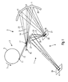
- FIG. 1 shows schematically an embodiment of an inventive Exposure system 1, which is an illumination system 2 and an imaging system 4.
- the lighting system 1 comprises a radiation source 3 in the form of a 1 schematically represented as a ring 5 synchrotrons, in which electrons revolve in the direction of an arrow 7 and emit synchrotron radiation.
- the beam feed can be direct or indirect for example deflecting mirrors, focusing components, wavelength selective components, etc.
- On the Diffractive optical component 15 is an interaction area 17 provided on the at least part of the beam 13 is directed so that from the point of view of the interaction area 17 the radiation striking it directly from a Source or an equivalent virtual source to come seems.
- wavelength-selective components such as Bragg monochromators or the like can cover all possible wavelength ranges the synchrotron radiation and the interaction area 17 are supplied.
- this is Radiation with a radiation wavelength of 0.1nm to 100nm, preferably 1nm to 50nm and in this case special Wavelengths around 13nm.
- the interaction region 17 There is a lattice structure in the interaction region 17 provided which is a reflection grating for the incident Radiation 13 represents.
- the incident radiation 13 reflects and thereby Grating diffraction split into three partial beams 19, 21 and 23, namely the ray 21 0 order, the ray 23 +1. Order and the beam 19 -1.
- Order Here is the divergence of the diffracted beams 19, 23 by the frequency spectrum of the incident beam 13 is determined because of the diffraction angle for a given grating period from the wavelength of the diffracted Light is dependent.
- the partial beams 19, 21 and 23 meet one focusing acting condenser mirror 25, which reflects the partial beams and aimed at the surface of a mask 27.
- the of the condenser 25 partial beams directed onto the mask 27 19, 21, 23 illuminate a common area lighting spot 29.
- Mask 27 is a reflection mask, the structure shown in FIG. 1 as straight line 28 at which the incident radiation 19, 21, 23 reflects becomes.
- the rays 19, 21, 23 illuminates which from three different spatial directions meet the mask 27. Accordingly, the rays 19, 21, 23 also by the structure specified on the mask 27 28 in three different spatial directions as rays 31, 33, 35 reflected.
- the reflected rays are from the Imaging system 4 recorded and imaged on a substrate 39.
- the imaging system 4 comprises a lens mirror 37, which rays 31, 33, 35 hit, and the latter on the substrate 39 such that the structures of the Mask 27 are imaged on the substrate 39.
- Figure 1 is accordingly the line structure 28 on the mask 27 on the Mapped substrate 39 by radiation only in the Area of a line segment 41 falls onto the substrate 39.
- the illumination system 1 is an imaging one System created that the mask 27 on the substrate 39th images, the mask 27 from several spatial directions is exposed even though the beam originating from the source 11 13 is highly collimated. It is based on that of the incident beam 13 with a given collinearity a lighting system with a comparatively high numerical Aperture realized, or in other words, the diffraction optical Component 15 has to increase the light conductance of the Lighting system contributed.
- the lattice structure can be adjusted by changing the lattice period, about the diffraction angles of beams 19 and 23 of-1. or +1. Change order. It is therefore possible to Angles at which the rays 19, 23 fall on the mask 27, also vary in time, so that within one Time a solid angle range for illuminating the mask 27 can be essentially completely illuminated.
- the lighting system 1 can be used, for example, in a method for producing a miniaturized component and there in particular in a photolithographic Methods section.
- the substrate in which the Component to be manufactured in advance with a radiation sensitive Layer coated.
- On the radiation sensitive Layer is then with the lighting system 1 of Figure 1 projected the pattern of the mask 27.
- the radiation sensitive Layer developed, and subsequently performed one or more processing steps that the Change substrate in certain areas, depending on the situation whether the area is an area with developed or not developed photosensitive layer.
- etching steps or doping steps, etc. into consideration.
- the lighting system 1 is shown in FIG. 1 as a simplified one System shown in functional representation. So there exist Condenser and the lens each from a mirror 25 or 37. However, it is possible to make the components more complex design and other beam-shaping in the beam path and inserting beam deflecting components. Such components and their use in a lithography system for example from US 5 973 826, US 6 033 079 and 6 142 641 known, these writings by reference in full be included in the present application.
- Illumination system 1 An essential component of that shown in Figure 1 Illumination system 1 is the diffraction optical component 15, on the interaction area 17 of the incident and to be deflected Beam 13 falls.
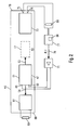
- This diffraction optical component is shown in more detail in Figure 2.
- This comprises a substrate 43 with a substrate surface 45 on which surface waves can be excited with high amplitude efficiency. Under The term surface waves are all wave phenomena here in the substrate matter to understand which one periodic change in the optical properties of the Guide substrate surface 45.
- SAW surface acoustic waves
- Surface waves polarized perpendicular to the surface of the substrate as well as surface waves polarized parallel to the surface, such as Bleustein-Gulyaev waves can be. It is also possible to superposition such Use waves.
- SAWs surface acoustic waves
- the substrate 43 is made from a single crystal of lithium niobate (LiNbO 3 ) in such a way that the substrate surface 45 forms a 128 ° rotY surface.
- the material lithium niobate was selected as the substrate material because it is a piezoelectric material and piezoelectric materials are particularly suitable for the excitation of surface waves by electrical voltages or fields in a surface wave source 47.
- there are also other suitable piezoelectric materials as substrates 43 such as lithium tantalate (LiTaO 3 ), quartz (SiO 2 ), lithium boron oxides (e.g.
- Li 2 B 4 O 7 aluminum phosphate (AlPO 4 ), gallium arsenide (GaAs ), Polybismuthites, especially bismuth germanium oxides (eg Bi 12 GeO 20 or Bi 12 SiO 20 ) and others.
- AlPO 4 aluminum phosphate
- GaAs gallium arsenide
- Polybismuthites especially bismuth germanium oxides (eg Bi 12 GeO 20 or Bi 12 SiO 20 ) and others.
- the surface wave source 47 comprises an electro-acoustic one Transducer 51, which is used to generate the surface waves required energy as electrical energy at connections 49 and 50 is supplied.
- the electroacoustic transducer 51 is a unidirectional transducer, which means that it has surface waves that converge into one Spread out by arrow 53, with generates a much higher intensity than surface waves, which is in an opposite direction to 53 Spread towards 54.
- the electroacoustic transducer 51 comprises a partial transducer 55 which is optimized with regard to the generation of surface waves with a wavelength ⁇ 1 of 30 ⁇ m, and a partial transducer 57 which is optimized with regard to the generation of surface waves with a wavelength ⁇ 2 of 20 ⁇ m is optimized.
- a partial transducer 57 which is optimized with regard to the generation of surface waves with a wavelength ⁇ 2 of 20 ⁇ m is optimized.
- wavelengths ⁇ in the range from approximately 2 ⁇ m to 100 ⁇ m, in particular 4 ⁇ m to 50 ⁇ m, with excitation frequencies from 50 MHz to 2 GHz are provided.
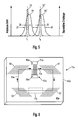
- FIG. 5 shows with curves 52 and 52 'a frequency characteristic of the electroacoustic transducer 51.
- curve 52 represents the surface wave intensity emitted by sub-transducer 55 as a function of the electrical excitation frequency of the transducer
- curve 52' correspondingly for sub-transducer 57 represents.
- the two partial transducers 55, 57 generate surface waves at different frequencies f 1 and f 2 with maximum intensity.
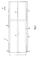
- the transducer 51 comprises a plurality of sets of finger electrodes, So-called interdigital electrodes, as shown in FIG. 4 becomes clear, which magnifies an area in which the partial transducers 55 and 57 of FIG. 3 adjoin one another.
- the converter 51 comprises a collecting electrode 59 on which the electrical connection 49 is provided and which is in the emission direction 53 extends.
- Another collecting electrode 60 extends parallel to the collecting electrode 59 with a Distance a of about 1 mm, and this second collecting electrode 60 is fed from the terminal 50.
- Each partial converter 55, 57 has an intermediate electrode 61 on the middle between the collecting electrodes 59 and 60th extends, with the intermediate electrode 61 of the partial converter 55 has a width of 50 ⁇ m and the collecting electrode 61 of the Partial converter 57 has a width of 20 microns.
- finger electrodes 62, 63, 64, 65, 66 and 67 extend perpendicular to the emission direction 53 between the collecting electrode 59 and the intermediate electrode 61 or the intermediate electrode 61 and the collecting electrode 60.
- finger electrodes extend from the collecting electrode 62 from that of one another have the pitch lambda, each having a width of ⁇ 1 / 8th or ⁇ 2/8 and end with a distance of 5 microns of the intermediate electrode 61st
- two finger electrodes 63 and 64 are arranged, each starting from the intermediate electrode 61 and ending at a distance of likewise 5 ⁇ m in front of the collecting electrode 59.
- the finger electrode 64 in this case has a width of ⁇ 1/4 or ⁇ 2/4 and is with respect to the finger electrode 63 displaced in the direction of emission 53 and disposed immediately adjacent to the finger electrode 63rd
- the finger electrode 63 has a width of ⁇ 1 / 8th or ⁇ 2/8.
- the structure of the finger electrodes 65, 66 and 67 extending between the intermediate electrode 61 and the collecting electrode 60 corresponds to the structure of the finger electrodes 62, 63 and 64 extending between the collecting electrode 59 and the intermediate electrode 61, in that the finger electrodes 67 each align with the finger electrodes 62 extend, a width of ⁇ 1 / 8th or ⁇ 2/8 exhibit and extending from the intermediate electrode 61st
- the finger electrodes 65 have a width of also ⁇ 1 / 8th or ⁇ 2/8, going from the collecting electrode 60 and are respectively aligned with the finger electrodes 63.
- the finger electrodes 66 have a width of ⁇ 1/4 or ⁇ 2 / 4 open, start from the collecting electrode 60 and are each aligned with the finger electrodes 64.
- each emanating from the collecting electrode 59 is aligned Finger electrode 62 with one of the intermediate electrode 61 outgoing finger electrode 67, and each of which Collecting electrode 60 outgoing finger electrode 65, 66 is aligned with a corresponding one starting from the intermediate electrode 61 Finger electrode 63 and 64.
- those of the collecting electrodes 59 outgoing finger electrodes 62 each offset to finger electrodes 65, 66 arranged by the Go out collecting electrode 60.
- This arrangement of the finger electrodes creates one Series connection, in which the between the collecting electrode 59 and the transducer regions arranged between the intermediate electrode 61 electrically in series with those between the intermediate electrode 61 and the collector electrode 60 arranged converter areas are switched. This leads to a voltage division, so that between adjacent pairs of partial electrodes (62-63, 64-62, 67-65, 66-67) only half of the voltage applied in the Operation between connections 49 and 50 is present.
- the partial transducers 55 and 57 are at a distance b from one another from 53.7 ⁇ m, i.e. that the one not provided with electrodes Area between the partial transducers 55, 57 has this width b.
- the electrode structure described is on the substrate surface formed by depositing an aluminum film then the gaps by means of microlithographic processes be etched out between the individual electrodes.
- alternative to form the electrode structure made of aluminum it is also possible to use other elements, especially metals, such as copper.
- the surface wave source 47 is amplified by an amplifier 71 fed, which is connected to the terminals 49 and 50. Those emitted from surface wave source 47 in direction 53 Surface waves pass through the interaction area 17 and form there to distract the incident Radiation 13 required radiation diffractive grating structure. In view of the highest possible diffraction efficiency doing, given the wavelength ⁇ of the surface waves, the electrical to source 47 through amplifier 71 Energy and the frequency f used for this are set in this way that the lattice amplitude, i.e. the amplitude of the surface waves in the interaction area 17, if possible is maximum.
- the diffraction-optical component 15 further comprises a surface wave receiver 73, which is also in the propagation path the surface waves emitted by the source 47 lies and on which the surface waves after passing through of the interaction region 17 meet.
- the surface wave receiver 73 comprises an acoustoelectric transducer, the mechanical energy of surface waves in electrical Converts energy and this electrical energy at connectors 75 and 76 provides.
- the voltage between the terminals 75 and 76 is therefore a Signal representing the intensity of the surface waves at the location of the receiver 73, and is controlled by a controller 77 recorded.
- the controller 77 acts as in FIG. 2 represented by an arrow 78 on the amplifier 71 and specifies the power and frequency, which of the Source 47 is to be fed.
- the controller 77 changes sizes Power P and frequency f so that the connections 75 and 76 tapped signal becomes maximum.
- this circuit causes the source 47th can be controlled so that the surface wave amplitude in the interaction area 17 is maximum.
- the acoustoelectric transducer of receiver 73 is similar constructed like the electroacoustic transducer 51 of the source 47, i.e. the acoustoelectric transducer also includes one Variety of finger electrodes or interdigital electrodes, which are connected to the connections 75 and 76.
- the embodiment of Figure 2 has the acoustoelectric Transducer of the receiver 73 has an electrode structure that the electrode structure of the electroacoustic transducer 51 in essentially corresponds.
- the structure is different however, with respect to a median plane between source 47 and the receiver 73 constructed symmetrically so that the wide Finger electrodes 64, 66 electrodes corresponding to source 47 of the receiver 73 in the emission direction 53 next to the each adjacent narrow electrodes are arranged, the correspond to the electrodes 63, 65.
- This also gives the Receiver 73 has a unidirectional characteristic, i.e. he receives surface waves propagating in the direction of 53 higher efficiency than the opposite Surface waves.
- the surface wave receiver 73 performs in addition to the function power P and to be supplied to the source 47 Frequency f also functions as a surface wave damper.
- the receiver 73 is optimized so that it as much of the mechanical energy of the surface waves as possible converts into electrical energy, this electrical Energy via lines connected to connections 75 and 76 dissipated and dissipated in a resistor 81.
- the resistor 81 is arranged at a distance from the substrate, so that the heat escaping in the resistor 81 the substrate 43 and in particular the interaction area 17 not heated and the optical effect of surface waves is not affected by temperature influences.
- the source 47 has one narrow-band frequency characteristic 52, 52 ', i.e. a
- the intensity of the surface waves emitted falls depending on from the excitation frequency on both sides of a maximum at frequency f with a characteristic width ⁇ f.
- FIG. 5 also shows the frequency characteristic of the surface wave receiver 73 entered as lines 84 and 84 ', which is the size of that provided at terminals 75 and 76 Measurement signal depending on the frequency of the represents incoming surface waves.
- Lines 84 too and 84 ' have a width on both sides of a center frequency ⁇ f falling characteristics.
- ⁇ f des Receiver 73 are the characteristic frequency widths ⁇ f des Receiver 73 larger than the frequency widths ⁇ f of the source 47.
- the receiver 73 is insensitive to minor Frequency changes of the source 47 so that the Controller 77 within a certain frequency range Source 47 based solely on the measurement signal at the connections 75, 76 with regard to a maximum amplitude of the surface waves can control in the interaction area 17.
- the controller 77 also has a memory 86 in which the frequency-dependent Sensitivity of the receiver 73, i.e. the history curve 84 of FIG. 5. This is it possible, even at frequencies farther from the central frequency Line 84 are removed, as shown in Figure 5 for the Excitation frequency f3 is the case, the source 47 is reliable head for.
- the frequency widths ⁇ f of the surface wave receiver 73 which are increased in comparison to the surface wave source 47, are achieved in that in principle the same electrode structure is selected for the acoustoelectric transducer of the receiver 73 as for the electroacoustic transducer of the source 47.
- the acoustoelectric transducer of the receiver 73 has the same Electrode structure, as shown in Figure 4 for the acoustoelectric transducer 51 of the source.
- the transducer of the source 73 in the direction 53 is shorter than the transducer of the source 47, that is, the transducer of the receiver 73 has fewer finger electrodes than the transducer of the source 47.
- the transducer has an acoustoelectric transducer 73 the one partial converter has a length of 40 ⁇ 1 and the other partial converter has a length of 35 ⁇ 2 .
- Another difference between the electrode structures of the source 47 transducer and the receiver 73 transducer is the distance between the electrode fingers.
- the substrate in the vicinity of the source 47 has a higher temperature than the substrate in the vicinity of the receiver 73, which results in a difference in the wavelengths of the surfaces at the location of the source 47 and at the location of the receiver 73.
- the wavelength at the location of the receiver 73 is then approximately 0.5% lower than at the location of the source 47. Therefore, the structure of the transducer in the receiver 73 is geometrically scaled downwards by 0.5% compared to the transducer in the source 47 that for the dimensioning of the transducer in the receiver 73 are used as parameters ⁇ 1 29.85 ⁇ m and as parameters ⁇ 2 19.9 ⁇ m.
- the center frequencies of the frequency characteristics 84 and 84 ' are each slightly shifted towards higher frequencies compared to the frequencies f 1 and f 2, respectively.
- 5 shows the frequency characteristics 52, 52 ', 84, 84' in a measurement in which the source 47 and receiver 73 have the same temperatures, so that the difference between the center frequencies of the frequency characteristics becomes clear.
- a temperature difference of approximately 70K occurs between the source 47 and the receiver 73, so that the center frequencies of the characteristics 52 and 84 or 52 'and 84' coincide approximately.
- the surface wave source 47 is not a perfect unidirectional characteristic has and therefore with a certain Intensity also surface waves in the direction 54 is emitted in the direction 54 next to the source 47
- Surface wave damper 87 provided this in the direction 54 to absorb emitted surface waves and their reflection back at an edge 88 of the substrate 43 to prevent the interaction area 17.
- the surface wave damper 87 is an acoustoelectric converter trained the mechanical energy of surface waves converted into electrical energy, which in a corresponding way matched resistor 89 is dissipated.
- electroacoustic transducer it is also possible to use other transducer types with unidirectional characteristics. It come both so-called single-phase and multi-phase Surface wave generator in question. Examples of this are, for example, the publications 4 521 711, US 4 736 172, US 4,910,839, US 5,073,763, US 5,162,689, US 5,264,751, US 5,365 206 and US 6,147,574, the disclosure of which in the this application is fully incorporated.
- Figure 6 shows another embodiment of an optical diffraction Component 15a, which is a substrate 43a made of piezoelectric Material with a substrate surface 45a includes. There is a surface wave source on the substrate surface 45a 47a arranged as an electroacoustic Converter is formed with connections 49a and 50a. The Interdigital electrodes of the electroacoustic transducer are only shown schematically in FIG.
- the electroacoustic transducer 51a also has a unidirectional characteristic on so that he prefers surface waves is emitted in a direction indicated by an arrow 53a.
- Interaction area 17a arranged for the interaction by the surface waves in this area formed structure with incident to be distracted diffractive radiation is provided.
- the embodiment shown in Figure 6 Compared to the embodiment of the diffractive optics shown in FIG Component has the embodiment shown in Figure 6 the advantage that the surface waves, the have passed through the interaction region 17a and their energy is destroyed. Rather, these surface waves remain circular closed propagation path 95a stored on the substrate 45a and can be used again to form the lattice structure contribute in the interaction area 17a.
- the Source 47a by a controller not shown in Figure 6 advantageously controlled so that the mirror 94 surface waves supplied to the source 47a and the constructive surface waves generated by the source 47a overlap.
- a surface wave receiver may be arranged to to control the surface wave source 47a in an optimized manner.
- the mirrors 91, 92, 93, 94 are Bragg mirrors with one Line grating formed, the dashes through in the Substrate surface 45a etched pits are formed. It However, it is also possible to use lattice lines through metallization films to form which on the substrate surface are upset.
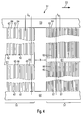
- FIG. 7 shows a substrate surface 45b of an optical diffraction component 15b, in which a surface wave source 47b emits surface waves of a frequency f 1 in a preferred direction 53b.
- a closed propagation path 95b is provided for the surface waves of the frequency f 0 via mirrors 91b, 92b, 93b and 94b, so that after passing through the closed propagation path 95b the surface waves finally pass through the surface source 47b again and are amplified there, similarly as in connection with the embodiment of Figure 6 has already been described.
- An interaction area for radiation to be deflected or diffracted is arranged between the mirrors 92b and 93b.
- the closed propagation paths 95b, 95b ', 95b "for surface waves of the frequencies f, f ', f " run together through the interaction area 17b and below divided by mirrors 93b “, 93b 'and 93b to again the surface wave sources 47b, 47b ', 47b “for the Frequencies f, f 'and f "to be supplied.
- the mirror 93b ' reflects Surface waves of frequency f ', while for surface waves the frequency f is also transparent.
- Each of the sources 47b, 47b 'and 47b "emits surface waves in a frequency spectrum, which depends on the control frequency changeable for the source within a certain range is.
- They are accordingly Deflection angle formed by the surface waves Lattice structure generated for the incident radiation can be varied in a particularly wide range.
- Sources 47b, 47b 'and 47 can be sequential in time are controlled so that the different deflection angles also be made available one after the other. Likewise it is possible to control the sources 47b, 47b 'and 47 "at the same time, so that the superposition of the corresponding surface waves with different wavelengths to form a multiple grating which leads the different deflection angles simultaneously provides.
- By overlaying the Surface waves with the frequencies f, f 'and f "and suitable Selecting these frequencies it is possible to use them in this way to overlay (to superpose) that a periodic lattice shape arises from the sinusoidal lattice shape differs.
- a so-called "blazed" Grating are provided in which certain diffraction orders specifically with higher diffraction intensity than other diffraction orders.
- Figures 6 and 7 are closed Propagation paths provided for the surface waves, the surface wave sources within the closed Paths of propagation lie.
- Figure 8 shows an embodiment in which on a surface 45c of a substrate 43c through mirrors 91c, 92c, 93c, 94c closed propagation path 95c is provided, wherein an interaction area between mirrors 94c and 91c 17c is arranged for incident radiation by the Propagation path 95c is traversed.
- a surface wave source 47c is outside the closed one Propagation path 95c arranged and emits surface waves in a preferred direction 53c.
- the surface wave source 47c on the substrate surface 45c arranged that the surface waves emitted by it on meet a mirror 97 located between mirrors 93c and 94c is arranged in the propagation path 95c.
- the Mirror 97 oriented so that it from the source 47c surface waves emitted in the direction 53c onto the Mirror 94c steers and thus already on the closed Propagation path 95c superimposed surface waves.
- For the surface waves coming from the mirror 93c mirror 97 is substantially transparent.
- a mirror resonator is thus provided by the mirrors 91c to 94c Surface waves formed, which by the source 47c with Surface waves that are fed through the mirror 97c in be coupled to the ring resonator.
- FIG. 9 shows an optical diffraction component 15d with a Substrate surface 45d on which an interaction region 17d for deflecting radiation by means of surface waves is provided.
- the surface waves are from a source 47d emitted in a preferred direction 53d. That from the source 47d emitted surface waves hit one after the other on mirrors 91d, 101, 102, 103, 104, 92d, 93d and 94d.
- the Interaction area is between mirrors 102 and 103 on the one hand and the mirrors 101 and 104 on the other hand and is run through twice by the surface waves, namely once in a direction 105 of surface waves, that run from the mirror 101 to the mirror 102, and on the other hand in a direction opposite to direction 105
- Direction 106 of surface waves emitted by the mirror 103 run to the mirror 104.
- FIG. 10 shows a further diffraction-optical component 15e, in one direction from a surface wave source 47e 53e surface waves emitted on a substrate surface 50e also in a closed propagation path 95e circulate. Similar to the embodiment in FIG. 9 there is also an interaction region 17e from the surface waves in two different directions 105e and 106e go through, which, however, in contrast to the embodiment not opposite to FIG. 9 but orthogonal are oriented towards each other.
- the Source 47e sequentially emitted surface waves Mirrors 91e, 101e, 102e, 103e, 104e and 94e reflected, before being returned to source 47e like this can be seen from Figure 10.
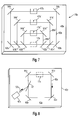
- FIG. 11 shows an optical diffraction component 15f with a Substrate 43f, on its substrate surface 45f an interaction area 17f is provided.
- the area of interaction is hit several times by a beam of surface waves go through different directions. For this, one emits Surface wave source 47f surface waves in a preferred direction 53f directly on the interaction area 17f.
- the Surface wave beam After passing through the interaction area 17f, the Surface wave beam then at a mirror 91f by 90 ° deflected, hits another mirror 92f, is on deflected by 135 ° and passes through the interaction area 17f again, in a direction that is 135 ° rotates to direction 53f of the first passage through the interaction area is oriented.
- the beam After going through again of the interaction region 17f, the beam strikes another mirror 93f, is deflected by 135 °, meets another mirror 94f, on which it in turn is deflected by 135 ° and then the interaction area 17f passes through again in a direction that rotated by 90 ° with respect to the direction of the second pass is oriented.
- the beam After the third pass through the interaction area 17f the beam passes through a surface wave receiver 73f, which emits a signal which the Surface wave intensity after the third pass of the interaction area 17f.
- the beam After going through of the receiver 73f, the beam is in a separate Surface wave damper 111 absorbed.
- the Surface waves another surface wave source 113 arranged, which of the surface waves after the second Pass through the interaction region 17f and which is the intensity of these surface waves can increase so that for the third pass through the Interaction area 17f an adjustable higher intensity of surface waves is available.
- a controller for this diffraction optical component 15f can the outputs of the surface wave receivers 73f and 73f 'read out the power or swelling strength of the two Adjust sources 47f and 113 absolutely and relative to each other, with regard to a desired lattice structure, which by the surface waves in the interaction area 17f is formed.
- the intensity of the two surface wave sources 47f and 113 relative to each other be varied to diffraction efficiency in different To influence spatial directions.
- a diffraction-optical component 15g shown in FIG comprises a substrate 43g, on the surface 45g of which there is an interaction region 17g is provided within a Surface wave resonator is arranged in the standing Surface waves can be generated.
- a Surface wave resonator is arranged in the standing Surface waves can be generated.
- are on the Substrate surface two opposite surface wave mirrors 117 and 119 provided between which surface waves a predetermined frequency band and run or form a standing surface wave field there can.
- the interaction region 17g is arranged as well as further a surface wave source 47g through which the resonator is fed with surface waves.
- the interaction area 17g is of a continuous Light beam illuminates, which is thus in the interaction area sees a lattice structure, its lattice amplitude alternating in time with twice the frequency of the surface waves increases and decreases. The changes accordingly diffraction efficiency provided by this grating with the double frequency of surface waves.
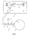
- FIG. 13 shows a further optical diffraction component 15h, in which in an interaction area 17h on a Substrate surface 45h by means of two facing one another Mirror 117h and 119h standing surface waves generated become.
- a surface wave source here, however 47h not arranged inside the resonator, but outside the same, in a preferred direction 53h of the source 47h emitted surface waves on a coupling mirror 97h which occurs within the resonator, i.e. between two mirrors 117h and 119h, is arranged and that of the Source 47h emits surface waves into the resonator where there is a field of standing surface waves formed.
- the diffraction-optical component 15h shown in FIG. 13 is Part of a lighting system 2h, which acts as a light source has a sychrotron radiation source 5h, which is shown in FIG 13 is only shown schematically.
- a sychrotron radiation source 5h which is shown in FIG 13 is only shown schematically.
- the synchrotron 5h bundles of charged particles run in the direction of arrow 7h around and thereby do not emit on one in FIG represented beam position pulsed synchrotron radiation, which is directed to the interaction area 17h is.
- a sensor 121 is provided on the synchrotron 5h, which emits a measurement signal that the time sequence of the in the synchrotron rotating particle packets and thus the represents the temporal sequence of the radiation pulses.
- the Sensor 121 can, for example, be a beam pickup coil or be similar.
- the measurement signal provided by the sensor 121 becomes one Frequency control 77h supplied, which the frequency of the surface wave source 47h emits surface waves determined, the frequency f of the surface waves on the Half the frequency of the radiation pulses is set.
- the frequency signal output from the frequency controller 77h a phase shift controller 123 which has a phase ⁇ sets the surface waves emitted by the source 47h and then drives an amplifier 71h which finally feeds the surface wave source 47h.
- the phase shift control 123 makes the phase ⁇ dependent a signal registered by a radiation sensor 125 on.
- the radiation sensor 125 measures the intensity of a predetermined one Diffraction order on the interaction area 17h falling radiation.
- the diffraction grating provided to the interaction region 17h depends on the radiation sensor 125 output measurement signal the diffraction efficiency of the grating.
- the Phase control 123 sets the phase ⁇ in such a way that the diffraction efficiency is maximum.
- the phase shift controller 123 can also be used for this switch off the diffracted beam, i.e. the phase ⁇ so that the diffraction efficiency is minimal. This can happen, for example, that the phase ⁇ so is set that the radiation pulses always on the Interaction area meet when the amplitude of the standing Waves there has a value of essentially zero.
- the Phase shift control 123 driven such that the of the surface wave source 47h emits surface waves in the correct phase in those formed by mirrors 117h and 119h Surface wave resonator are coupled.
- the phase shift control 123 makes the phase angle ⁇ dependent from the radiation intensity sensor 125.
- the Radiation sensor 125 can be the intensity of the first or second or higher order diffracted radiation.
- phase shift control 123 the phase angle ⁇ does not depend on one Measurement signal of a radiation sensor sets, but in dependence from a measurement signal by a surface wave receiver is provided, which is the amplitude of the in surface waves occurring to the surface wave resonator detected.
- phase shift control depending from the measurement signal of a radiation sensor or a surface wave receiver is on all previously described Embodiments applicable in which either standing Surface waves or in a closed propagation path revolving surface waves are generated.
- directions of propagation were the surface waves mostly through mirrors, which is at an angle of 45 ° to the original direction of propagation the surface waves are arranged by 90 ° distracted from their original direction of propagation.
- This illustration has been made for the sake of simplicity. It however, it is noted that the propagation of surface waves often due to anisotropic effects in the material of the substrate is influenced or determined. That's why it is possible that the angular relationship between incident and falling beam upon reflection a mirror is not satisfied here with surface waves. Accordingly, an angle of incidence of surface waves is on a mirror is not always the same angle of reflection.
Abstract
Description
Die Erfindung betrifft eine beugungsoptische Komponente zur Bereitstellung einer strahlungsbeugenden Gitterstruktur, wobei die Gitterstruktur zur Beugung und Ablenkung eines einfallenden Lichtstrahls durch Oberflächenwellen auf einer Oberfläche eines Substrats bereitstellbar ist. Eine Wellenlänge des an der Gitterstruktur zu beugenden Lichtes kann zunächst eine beliebige Wellenlänge aus dem optischen Spektrum sein. Insbesondere betrifft die Erfindung jedoch eine beugungsoptische Komponente zur Bereitstellung einer Gitterstruktur zur Beugung von Licht in den Bereichen des Ultraviolett, des extremen Ultraviolett (EUV), mit Wellenlängen von etwa 0,1nm bis etwa 100nm, sowie des Röntgenbereichs. Die Erfindung betrifft weiter ein Beleuchtungssystem mittels welchem ein Lichtstrahl, insbesondere aus den Wellenlängenbereichen Ultraviolett, extremes Ultraviolett und Röntgen, ablenkbar und steuerbar ist. Ferner betrifft die Erfindung ein Belichtungssystem zum Abbilden eines an einer Maske bereitgestellten Musters auf ein Substrat, wobei ein zur Abbildung eingesetzter Lichtstrahl durch die beugungsoptische Komponente steuerbar ist und wobei das Muster insbesondere Komponenten eines miniaturisierten Bauelements darstellt. Ferner betrifft die Erfindung ein Belichtungsverfahren zur Herstellung eines miniaturisierten Bauelements mit einem photolithographischen Schritt.The invention relates to an optical diffraction component for Provision of a radiation diffractive grating structure, the lattice structure for diffraction and deflection of a incident light beam by surface waves on a Surface of a substrate can be provided. One wavelength of the light to be diffracted at the grating structure first any wavelength from the optical spectrum his. In particular, however, the invention relates to one Diffractive optical component for providing a grating structure for diffraction of light in the areas of the ultraviolet, of extreme ultraviolet (EUV), with wavelengths of about 0.1nm to about 100nm, as well as the X-ray range. The The invention further relates to a lighting system which is a light beam, especially from the wavelength ranges Ultraviolet, extreme ultraviolet and x-ray, is distractible and controllable. The invention further relates to an exposure system for imaging a provided on a mask Patterns on a substrate, one for illustration used light beam through the diffraction optical Component is controllable and the pattern in particular Components of a miniaturized device. The invention further relates to an exposure method for Production of a miniaturized component with one photolithographic step.
Bei der Herstellung von miniaturisierten Bauelementen, insbesondere von Halbleiter-Bauelementen, wird herkömmlicherweise ein photolithographischer Schritt eingesetzt, um auf einer Maske vorgegebene Strukturen auf ein mit einer strahlungsempfindlichen Schicht versehenes Substrat abzubilden und dabei die strahlungsempfindliche Schicht zu belichten. Eine untere Grenze von Abmessungen der abgebildeten Strukturen (CD, "critical dimension") ist dabei durch die Wellenlänge des für die Abbildung verwendeten Lichts vorgegeben. Bei immer kleiner werdenden Strukturen der herzustellenden miniaturisierten Bauelemente sind deshalb immer kürzere Wellenlängen des Lichts zur Abbildung einzusetzen. Allerdings sind für Wellenlängen unterhalb Ultraviolett abbildende optische Komponenten und Komponenten zur Strahlführung bzw. Ablenkung schwer handhabbar bzw. Technologien für solche Komponenten noch nicht ausreichend entwickelt. Beispiele für Beleuchtungsoptiken im Bereich des EUV sind aus US 5 973 826, 6 033 079 und US 6 142 641 bekannt.In the manufacture of miniaturized components, in particular of semiconductor devices, is traditionally a photolithographic step used to get on a Mask predetermined structures onto one with a radiation sensitive Imaging layered substrate and thereby to expose the radiation sensitive layer. A lower one Limit of dimensions of the structures shown (CD, "critical dimension") is due to the wavelength of the for given the image used light. With always smaller structures of the miniaturized to be manufactured Components are therefore always shorter wavelengths of the Use light for illustration. However, are for wavelengths below ultraviolet imaging optical components and components for beam guidance or deflection are difficult to handle or technologies for such components not yet sufficiently developed. Examples of lighting optics in the The range of the EUV are from US 5 973 826, 6 033 079 and US 6 142 641 known.
Aus ESRF, "Annual Report, 1995/1996:ID32" in
http://www.esrf.fr/info/science/annrep/95-
96/report/exp/id32/id32.htm (29.01.2001) ist ein Röntgenstrahlchopper
bekannt, welcher Röntgenstrahlung durch ein
schaltbares optisches Gitter schaltet, welches durch Oberflächenwellen
(SAW, SURFACE ACOUSTIC WAVES ) bereitgestellt
ist. Allerdings ist bei dieser bekannten Anordnung eine Beugungsintensität
des SAW-Gitters und damit eine Intensität des
schaltbaren Strahls zu gering, als daß sich die dort beschriebene
Oberflächenwellen-Bauanordnung zum wirtschaftlichen
Einsatz in Lithographieverfahren eignen würde.From ESRF, "Annual Report, 1995/1996: ID32" in http://www.esrf.fr/info/science/annrep/95-
96 / report / exp / id32 / id32.htm (29.01.2001) an X-ray chopper is known which switches X-rays through a switchable optical grating provided by surface waves (SAW, SURFACE ACOUSTIC WAVES). In this known arrangement, however, a diffraction intensity of the SAW grating and thus an intensity of the switchable beam is too low for the surface wave construction arrangement described there to be suitable for economical use in lithography processes.
Es ist eine Aufgabe der vorliegenden Erfindung, eine beugungsoptische Komponente zur Bereitstellung einer strahlungsbeugenden Gitterstruktur vorzuschlagen, welche bei insbesondere kurzen Lichtwellenlängen eine effiziente Strahlsteuerung und Strahlablenkung ermöglicht. Ferner ist es eine Aufgabe der Erfindung eine beugungsoptische Komponente zur Bereitstellung einer strahlungsbeugenden Gitterstruktur mit hoher Beugungseffizienz bei kurzen optischen Wellenlängen vorzuschlagen.It is an object of the present invention to provide an optical diffraction Component for providing a radiation diffractive To propose lattice structure, which in particular efficient light control with short light wavelengths and beam deflection. It is also a task the invention provides a diffractive optical component a radiation diffractive lattice structure with a high Propose diffraction efficiency at short optical wavelengths.
Ferner ist es eine Aufgabe der vorliegenden Erfindung, eine beugungsoptische Komponente vorzuschlagen, welche eine Strahlablenkung in mehreren Raumrichtungen ermöglicht.It is also an object of the present invention to provide a propose diffraction optical component, which a Beam deflection in several spatial directions possible.
Eine Aufgabe der Erfindung ist es weiter, ein Belichtungssystem vorzuschlagen, welches sich zur Abbildung vergleichsweise kleiner Muster eignet. Insbesondere ist es eine Aufgabe der Erfindung, ein solches Belichtungssystem vorzuschlagen, welches eine vergleichsweise hohe numerische Apertur aufweist.Another object of the invention is an exposure system to propose which is comparatively the figure small pattern. In particular, it is a job the invention to propose such an exposure system, which has a comparatively high numerical aperture.
Weiter ist es noch eine Aufgabe der Erfindung ein Verfahren zur Herstellung eines Bauelements vorzuschlagen, welches insbesondere zur Herstellung von Bauelementen mit kleinen Strukturen geeignet ist.Another object of the invention is a method to propose for the manufacture of a component which especially for the production of components with small Structures is suitable.
Die Erfindung geht aus von einer beugungsoptischen Komponente zur Bereitstellung einer strahlungsbeugenden Gitterstruktur, welche eine Oberflächenwellen-Bauanordnung umfaßt, die ein Substrat, eine Oberflächenwellenquelle zur Erzeugung von Oberflächenwellen auf einer Oberfläche des Substrats und einen Wechselwirkungsbereich der Substratoberfläche aufweist, der für eine Wechselwirkung der Strahlung mit einer Gitterstruktur vorgesehen ist, welche durch die erzeugten Oberflächenwellen bereitgestellt ist.The invention is based on an optical diffraction component to provide a radiation diffractive grating structure, which comprises a surface acoustic wave device assembly comprising a Substrate, a surface wave source for generating Surface waves on a surface of the substrate and has an interaction area of the substrate surface, for an interaction of the radiation with a lattice structure is provided, which is generated by the surface waves is provided.
Unter einem ersten Aspekt liegt der Erfindung die Erkenntnis zugrunde, daß durch die SAW-Gitterstruktur dann eine hohe Beugungseffizienz bereitgestellt werden kann, wenn die SAW-Gitterstruktur ein qualitativ hochwertiges Beugungsgitter erzeugt, welches im Idealfall durch Wellenzüge von Oberflächenwellen gebildet ist, deren Profile im gesamten Wechselwirkungsbereich gleiche, vorzugsweise im wesentlichen sinusähnliche oder sinusförmige Gestalt aufweisen. In dieser Hinsicht wurde festgestellt, daß die Oberflächenwellenquelle der herkömmlichen beugungsoptischen Komponente neben Oberflächenwellen, die hin zu dem Wechselwirkungsbereich emittiert werden, auch Oberflächenwellen emittiert, die nicht zu dem Wechselwirkungsbereich gerichtet sind. Diese eigentlich von dem Wechselwirkungsbereich weg gerichteten Oberflächenwellen werden allerdings an Rändern des Substrats reflektiert und gelangen gegebenenfalls über Umwege schließlich doch in den Wechselwirkungsbereich, wo sie die Profile der direkt von der Oberflächenwellenquelle zu dem Wechselwirkungsbereich hin emittierten Oberflächenwellen stören und damit schließlich die Qualität des optischen Gitters senken.The invention lies in a first aspect of the knowledge based on the fact that the SAW lattice structure then has a high Diffraction efficiency can be provided if the SAW grating structure a high quality diffraction grating generated, which ideally by wave trains of surface waves is formed, whose profiles in the entire interaction area same, preferably essentially sinusoidal or have a sinusoidal shape. In this Regarding this, it was found that the surface wave source the conventional diffractive optical component in addition to surface waves, which emits towards the interaction area are also emitted surface waves that are not to the Interaction area are directed. This actually from surface waves directed away from the interaction area are reflected at the edges of the substrate and eventually reach the Interaction area where they get the profiles of the directly from the Surface wave source towards the interaction area emitted surface waves and ultimately interfere lower the quality of the optical grating.
Im Hinblick auf eine Reduzierung derartiger über Umwege unerwünscht in den Wechselwirkungsbereich gelangender Oberflächenwellen wurde bereits vorgeschlagen, in Ausbreitungswegen von Oberflächenwellen, die nicht direkt zum Wechselwirkungsbereich gerichtet sind, Oberflächenwellendämpfer aus elastischem Material auf das Substrat aufzubringen. Allerdings ist auch die Dämpfungseffizienz derartiger bekannter Dämpfer nicht immer ausreichend.With a view to reducing such undesirable via detours surface waves entering the interaction area has already been suggested in ways of propagation of surface waves that are not directly related to the interaction area are directed from surface wave dampers to apply elastic material to the substrate. Indeed the damping efficiency of such is more well known Damper is not always sufficient.
Unter dem ersten Aspekt liegt der Erfindung nun die Idee zugrunde, Oberflächenwellen, die nicht hin zu dem Wechselwirkungsbereich emittiert werden, auf dem Substrat gar nicht erst zu erzeugen.Under the first aspect, the invention is the idea underlying surface waves that are not towards the interaction area be emitted, not at all on the substrate to generate first.
Hierzu schlägt die Erfindung vor, als Oberflächenwellenquelle eine unidirektionale Quelle, d.h. eine Oberflächenquelle mit einer Richtcharakteristik vorzusehen, welche Oberflächenwellen in eine Vorzugsrichtung stärker emittiert als in eine hierzu entgegengesetzte Richtung, und dabei die Oberflächenwellenquelle relativ zu dem Wechselwirkungsbereich derart anzuordnen, daß die in die Vorzugsrichtung emittierten Oberflächenwellen den Wechselwirkungsbereich, gegebenenfalls auch nach Ablenkung mittels Oberflächenwellenspiegeln oder ähnlichem, durchlaufen.To this end, the invention proposes as a surface wave source a unidirectional source, i.e. a surface source with a directional characteristic to provide which surface waves emits more in a preferred direction than in one opposite direction, and the surface wave source relative to the interaction area like this to arrange that the surface waves emitted in the preferred direction the interaction area, if necessary also after distraction by means of surface wave mirrors or similar, go through.
Durch den Einsatz einer solchen unidirektionalen Oberflächenwellenquelle wird somit die Entstehung von unerwünschten Oberflächenwellen vermieden, welche nicht wie gewünscht auf den Wechselwirkungsbereich gerichtet sind und indirekt und unerwünscht in diesen reflektiert werden könnten.By using such a unidirectional surface wave source thus the emergence of undesirable Avoided surface waves, which do not work as desired the interaction area are directed and indirect and could be undesirably reflected in these.
Unter einem weiteren Aspekt liegt der Erfindung der Gedanke zugrunde, daß im Hinblick auf eine Steuerung und Änderung des Ablenk- bzw. Beugungswinkels zwischen einfallendem und ausfallendem Strahl eine Gitterkonstante der Gitterstruktur änderbar sein muß. Hierzu ist die herkömmliche beugungsoptische Komponente jedoch nur in sehr beschränktem Umfang in der Lage. Der Erfindung liegt demgemäß die Idee zugrunde, in der Oberflächenwellen-Bauanordnung eine Oberflächenwellenquelle einzusetzen, welche zur Emission von Oberflächenwellen bei mehreren voneinander verschiedenen Wellenlängen ausgelegt ist.The idea lies in a further aspect of the invention underlying that with a view to controlling and changing the Deflection or diffraction angle between incoming and outgoing Beam a lattice constant of the lattice structure must be changeable. This is the conventional diffraction optical Component, however, only to a very limited extent in the Location. The invention is accordingly based on the idea in which Surface wave assembly a surface wave source use, which contribute to the emission of surface waves designed several different wavelengths is.
Die Erfindung zeichnet sich unter diesem Aspekt dadurch aus, daß die Oberflächenwellenquelle einen elektroakustischen Wandler mit einer Elektrodenstruktur umfaßt, welche ein Vielzahl von Teilelektroden aufweist, die mit Abstand zu benachbarten Teilelektroden angeordnet sind. Hierbei ist in der Elektrodenstruktur eine Mehrzahl von Bereichen vorgesehen, welche in Emissionsrichtung der Oberflächenwellen nebeneinander und mit Abstand voneinander angeordnet sind und wobei in einem jeden der Bereiche die Teilelektroden periodisch angeordnet sind. Die verschiedenen Bereiche unterscheiden sich dadurch voneinander, daß die Anordnungsperioden der Teilelektroden in den jeweiligen Bereichen voneinander verschieden sind. In this aspect, the invention is characterized in that that the surface wave source is an electroacoustic Transducer having an electrode structure comprising a plurality of sub-electrodes that are spaced from neighboring ones Sub-electrodes are arranged. Here is in the Electrode structure provided a plurality of areas which are side by side in the emission direction of the surface waves and are spaced from each other and wherein in the partial electrodes are arranged periodically in each of the regions are. The different areas differ in that the arrangement periods of the partial electrodes different from each other in the respective areas are.
Da die Anordnungsperiode von Teilelektroden eines Bereichs die Wellenlänge festlegt, bei der dieser Bereich Oberflächenwellen mit erhöhter Effizienz emittiert, ist durch die Bereitstellung der Bereiche mit unterschiedlichen Anordnungsperioden insgesamt eine Oberflächenwellenquelle geschaffen, welche in einem vergleichsweise breiten Wellenlängenbereich Oberflächenwellen mit verhältnismäßig hoher Effizienz emittieren kann.Since the arrangement period of sub-electrodes of one area specifies the wavelength at which this area is surface waves is emitted with increased efficiency by providing of the areas with different arrangement periods created a total surface wave source, which in a comparatively broad wavelength range Emit surface waves with relatively high efficiency can.
Unter einem weiteren Aspekt geht die Erfindung von dem Gedanken aus, daß zur Erzielung einer hohen Beugungseffizienz ein Oberflächenwellengitter mit hoher Oberflächenwellenamplitude bereitzustellen ist. Bei einer Oberflächenquelle mit elektroakustischem Wandler kann die Amplitude der emittierten Oberflächenwellen dadurch erhöht werden, daß an Elektroden des elektroakustischen Wandlers Wechselspannungen mit höherer Spannungsamplitude angelegt werden. Allerdings sind einer an den elektroakustischen Wandler maximal anlegbaren Spannungsamplitude in der Praxis durch elektrische Überschläge zwischen Elektroden und Teilelektroden des Wandlers Grenzen gesetzt.In another aspect, the invention is based on the idea from that to achieve high diffraction efficiency Surface wave grating with high surface wave amplitude is to be provided. With a surface source with electro-acoustic Transducers can change the amplitude of the surface waves emitted be increased by the fact that electrodes of electroacoustic transducer AC voltages with higher Voltage amplitude can be applied. However, one is on the electroacoustic transducer maximum applicable voltage amplitude in practice by electrical flashovers limits between electrodes and partial electrodes of the transducer set.
Der Erfindung liegt unter diesem Aspekt die Idee zugrunde, einen elektroakustischen Wandler einzusetzen, welcher bei Anlegen einer vergleichsweise niedrigen Spannung bereits Oberflächenwellen mit hoher Amplitude erzeugt.In this aspect, the invention is based on the idea to use an electroacoustic transducer, which at Applying a comparatively low voltage already Surface waves generated with high amplitude.
Unter diesem Aspekt zeichnet sich die Erfindung dadurch aus, daß der elektroakustische Wandler zwei Gruppen von Fingerelektroden aufweist, wobei die Fingerelektroden einer jeden Gruppe elektrisch leitend miteinander verbunden und die Fingerelektroden unterschiedlicher Gruppen elektrisch voneinander isoliert sind. An diese Gruppen von Fingerelektroden wird die elektrische Antriebswechselspannung im Betrieb des elektroakustischen Wandlers angelegt. Zwischen Paaren von Fingerelektroden unterschiedlicher Gruppen ist wenigstens eine von den Fingerelektroden der beiden Gruppen jeweils elektrisch isolierte Zwischenelektrode vorgesehen. Das elektrische Potential dieser Zwischenelektrode ist vorzugsweise sich frei einstellend (floating), so daß über die Komponenten Fingerelektrode der ersten Gruppe, Zwischenelektrode und Fingerelektrode der anderen Gruppe gewissermaßen ein Spannungsteiler bereitgestellt ist, bei welchem eine zwischen zwei benachbarten Elektroden auftretende elektrische Spannung geringer ist als die insgesamt zwischen den Gruppen von Fingerelektroden anliegende Spannung. Durch diese Maßnahme wird die Neigung zu Überschlägen zwischen Elektroden des elektroakustischen Wandlers wirksam reduziert, wobei gleichwohl von dem elektroakustischen Wandler Oberflächenwellen hoher Amplitude emittiert werden können.In this aspect, the invention is characterized by that the electroacoustic transducer has two groups of finger electrodes has, the finger electrodes of each Group electrically connected and the finger electrodes different groups electrically from each other are isolated. To these groups of finger electrodes the electrical drive AC voltage in the operation of the electroacoustic Transducer. Between pairs of finger electrodes different groups is at least one of the finger electrodes of the two groups each electrically insulated intermediate electrode provided. The electrical potential this intermediate electrode is preferably free adjusting (floating) so that over the components finger electrode the first group, intermediate electrode and finger electrode the other group a voltage divider is provided, in which one between two adjacent Electrode voltage is lower is as the total between the groups of finger electrodes applied voltage. This measure will Tendency to flashover between electrodes of the electroacoustic Converter effectively reduced, although from that electro-acoustic transducer surface waves of high amplitude can be emitted.
Vorzugsweise weist auch die Zwischenelektrode, ebenso wie die Fingerelektroden, eine periodische Struktur auf, wobei von der Zwischenelektrode Zweigelektroden ausgehen, welche sich zwischen benachbarten Fingerelektroden erstrecken.Preferably, the intermediate electrode, as well as the Finger electrodes, a periodic structure, whereby of the intermediate electrode branch electrodes, which are extend between adjacent finger electrodes.
Bei dieser ineinandergreifenden Struktur von Fingerelektroden und Zweigelektroden ist es im Hinblick auf die Wirkung der Gesamtelektrodenstruktur als Spannungsteiler vorteilhaft, daß sich die Fingerelektroden verschiedener Gruppen zueinander parallel versetzt, allerdings vorzugsweise nicht auf einer gemeinsamen Geraden erstrecken. Hierbei ist es ebenfalls vorteilhaft, wenn Fingerelektroden und Zweigelektroden einander paarweise zugeordnet sind und die einander zugeordneten Zweig- bzw. Fingerelektroden sich in etwa auf jeweils gemeinsamen Geraden erstrecken.With this interlocking structure of finger electrodes and branch electrodes it is in terms of the effect of Overall electrode structure as a voltage divider advantageous that the finger electrodes of different groups to each other offset in parallel, but preferably not on one extend common straight lines. It is also here advantageous if finger electrodes and branch electrodes are each other are assigned in pairs and are assigned to each other Branch or finger electrodes are roughly common Straight lines.
Unter einem weiteren Aspekt liegt der Erfindung wiederum die Erkenntnis zugrunde, daß zur Erzielung einer hohen Beugungseffizienz eine hohe Amplitude der die strahlungsbeugende Gitterstruktur bereitstellenden Oberflächenwellen notwendig ist. Hierbei liegt der Erfindung die Idee zugrunde, eine Frequenz zur Erregung der Oberflächenwellequelle so einzustellen, daß die Amplitude der von der Oberflächenquelle emittierten Oberflächenwellen im wesentlichen maximal ist.In another aspect, the invention is again the Understanding that to achieve high diffraction efficiency a high amplitude of the radiation diffractive Surface waves providing lattice structure necessary is. Here, the invention is based on the idea of a Set the frequency to excite the surface wave source so that the amplitude of that from the surface source emitted surface waves is essentially maximum.
Unter diesem Aspekt zeichnet sich die Erfindung dadurch aus, daß auf dem Substrat ein Oberflächenwellenempfänger für von der Oberflächenwellenquelle emittierte Oberflächenwellen vorgesehen ist, der ein Meßsignal bereitstellt, welches eine Amplitude der Oberflächenwellen repräsentiert, die auf den Oberflächenwellenempfänger treffen. Es ist dann weiter eine Steuerung vorgesehen, welche die Frequenz zur Erregung der Oberflächenwellenquelle in Abhängigkeit von dem Meßsignal des Oberflächenwellenempfängers einstellt.In this aspect, the invention is characterized by that on the substrate a surface wave receiver for from surface waves emitted by the surface wave source is provided, which provides a measurement signal, which a Represents the amplitude of the surface waves on the Hit surface wave receiver. Then it is still one Control provided which the frequency to excite the Surface wave source depending on the measurement signal of the Surface wave receiver sets.
Hierdurch ist eine Anordnung bereitgestellt, die es erlaubt, die Frequenz zur Erregung der Oberflächenwellenquelle so lange, gegebenenfalls iterativ, abzuändern, bis die Amplitude der empfangenen Oberflächenwellen im wesentlichen maximal ist. Es kann dann davon ausgegangen werden, daß auch die Oberflächenwellenquelle Oberflächenwellen mit maximaler Amplitude emittiert und daß dann ferner auch die Gitterstruktur in dem Wechselwirkungsbereich durch Oberflächenwellen maximaler Amplitude bereitgestellt ist.This provides an arrangement that allows the frequency to excite the surface wave source so long, if necessary iteratively, to change until the amplitude of the received surface waves essentially maximum is. It can then be assumed that the Surface wave source Surface waves with maximum amplitude emitted and that then also the lattice structure maximum in the interaction area by surface waves Amplitude is provided.
Eine im Hinblick auf die Emission von Oberflächenwellen mit möglichst hoher Amplitude ausgelegte Oberflächenwellenquelle weist typischerweise in Abhängigkeit von der Erregungsfrequenz einen Verlauf der Amplitude der emittierten Oberflächenwellen derart auf, daß bei einer Zentralfrequenz die Amplitude der erzeugten Oberflächenwellen maximal ist und beidseits der Zentralfrequenz die Amplitude mit einer charakteristischen Frequenzbreite abnimmt. Ebenso weist typischerweise ein Oberflächenwellenempfänger bei gleichbleibender Amplitude der empfangenen Oberflächenwellen in Abhängigkeit von der Oberflächenwellenfrequenz einen Verlauf des Meßsignals auf, der ebenfalls beidseits einer Zentralfrequenz mit einer charakteristischen Frequenzbreite abfällt.One with regard to the emission of surface waves surface wave source designed as high as possible typically shows depending on the excitation frequency a course of the amplitude of the emitted surface waves such that at a central frequency Amplitude of the generated surface waves is maximum and the amplitude with a characteristic on both sides of the central frequency Frequency width decreases. Also typically shows a surface wave receiver with the same Amplitude of the received surface waves depending a course of the measurement signal from the surface wave frequency on, which is also on both sides of a central frequency of a characteristic frequency range.
Vorzugsweise sind die Oberflächenwellenquellen und der Oberflächenwellenempfänger derart aufeinander abgestimmt, daß die charakteristische Frequenzbreite der Oberflächenwellenquelle kleiner ist als die typische Frequenzbreite des Oberflächenwellenempfängers. Hierdurch ist es möglich, zum einen die Oberflächenquelle im Hinblick auf die Emission hoher Amplituden zu optimieren und zum anderen einen Empfänger bereitzustellen, der bei verschiedenen Mittelfrequenzen der Oberflächenwellenquelle mit guter Effizienz Oberflächenwellen empfangen kann. Diese Auslegung ist insbesondere unter dem Gesichtspunkt vorteilhaft, daß die Mittelfrequenz an der Oberflächenwellenquelle aufgrund beispielsweise von Temperaturdriften zeitlich nicht konstant sein muß oder die Oberflächenwellenquelle zur Änderung des Ablenk- bzw. Beugungswinkels gezielt mit sich ändernden Frequenzen angesteuert wird. Es ist dann möglich, die Frequenz zur Erregung der Oberflächenwellenquelle in Abhängigkeit von alleine dem Meßsignal des Oberflächenwellenempfängers einzustellen, um im wesentlichen die maximal mögliche Oberflächenwellenamplitude zu erreichen.The surface wave sources and the surface wave receiver are preferably so coordinated that the characteristic frequency range of the surface wave source is smaller than the typical frequency range of the surface wave receiver. This makes it possible on the one hand Surface source with regard to the emission of high amplitudes to optimize and secondly to provide a receiver, that at different center frequencies of the surface wave source Receive surface waves with good efficiency can. This interpretation is particularly from the point of view advantageous that the center frequency at the surface wave source due to temperature drifts, for example does not have to be constant over time or the surface wave source to change the deflection or diffraction angle is controlled with changing frequencies. It is then possible to use the frequency to excite the surface wave source depending on the measurement signal alone of the surface acoustic wave receiver to set substantially to achieve the maximum possible surface wave amplitude.
Im Hinblick auf eine noch genauere Einstellung der Frequenz zur Erzeugung der maximal möglichen Oberflächenwellenamplitude wird die Frequenz neben der Abhängigkeit von dem Meßsignal auch noch in Abhängigkeit von dem Verlauf des Meßsignals in Abhängigkeit von der Frequenz gesteuert. Dadurch wird auch der Abhängigkeit des Meßsignals von der Frequenz Rechnung getragen und eine noch genauere Frequenzeinstellung ermöglicht.With a view to setting the frequency even more precisely to generate the maximum possible surface wave amplitude the frequency in addition to the dependence on the measurement signal also depending on the course of the measurement signal controlled depending on the frequency. This will also the dependence of the measurement signal on the frequency calculation worn and allows an even more precise frequency setting.
Unter einem weiteren Aspekt geht die Erfindung wiederum davon aus, daß zur Erreichung einer hohen Beugungseffizienz eine Gitterstruktur mit hoher Gitterqualität notwendig ist. Unter diesem Aspekt liegt der Erfindung die Erkenntnis zugrunde, daß Oberflächenwellen, welche von der Oberflächenwellenquelle emittiert wurden, nach Durchlaufen des Wechselwirkungsbereichs auf dem Substrat weiter propagieren, bis sie schließlich auf einen Substratrand treffen und von diesem, gegebenenfalls über Umwege, zurück in den Wechselwirkungsbereich reflektiert werden und dort die Profile der eigentlich gewünschten Gitterstruktur stören.In another aspect, the invention again proceeds from this from that to achieve a high diffraction efficiency Lattice structure with high lattice quality is necessary. Under this aspect is the basis of the invention, that surface waves coming from the surface wave source were emitted after passing through the interaction area continue to propagate on the substrate until finally meet and from a substrate edge, if necessary via detours, back into the interaction area are reflected and there the profiles of the actually desired Disrupt grid structure.
Unter diesem Aspekt schlägt die Erfindung vor, die Oberflächenwellen nach Durchlaufen des Wechselwirkungsbereichs durch einen Oberflächenwellendämpfer zu dämpfen, so daß eine Intensität an in den Wechselwirkungsbereich zurückreflektierten Oberflächenwellen möglichst gering ist.In this aspect, the invention proposes surface waves after passing through the interaction area to dampen a surface wave damper so that an intensity to reflect back into the interaction area Surface waves is as low as possible.
Ein solcher Oberflächenwellendämpfer kann beispielsweise aus elastomerem Material gebildet sein, welches auf das Substrat aufgebracht ist und in welchem die mechanische Energie der Oberflächenwellen in thermische Energie dissipiert wird. Ein Nachteil eines solchen Oberflächenwellendämpfers liegt darin, daß er Wärme auf dem Substrat erzeugt, was zu einer Änderung der Ausbreitungseigenschaften der Oberflächenwellen auf dem Substrat führt.Such a surface wave damper can, for example elastomeric material formed on the substrate is applied and in which the mechanical energy of Surface waves are dissipated in thermal energy. On The disadvantage of such a surface wave damper is that that it generates heat on the substrate, causing a change the propagation properties of surface waves on the Leads substrate.
Gemäß einer bevorzugten Ausführungsform der Erfindung ist deshalb vorgesehen, daß der Oberflächenwellendämpfer als akustoelektrischer Wandler ausgebildet ist, um die mechanische Energie der Oberflächenwellen am Ort des Oberflächenwellendämpfers in elektrische Energie umzuwandeln. Die elektrische Energie kann dann insbesondere ohne thermische Belastung des Substrats von diesem weg transportiert und an von dem Substrat entfernter Stelle in geeigneter Weise dissipiert werden, so daß eine thermische Belastung des Substrats durch den Oberflächenwellendämpfer vergleichsweise gering ist. According to a preferred embodiment of the invention therefore provided that the surface wave damper as acoustoelectric converter is designed to the mechanical Surface wave energy at the location of the surface wave damper convert into electrical energy. The electrical Energy can then in particular without thermal stress of the substrate is transported away from it and on from that Substrate distant site dissipated in a suitable manner be so that a thermal load on the substrate the surface wave damper is comparatively low.
Hierzu weist der akustoelektrische Wandler vorzugsweise wenigstens zwei elektrische Anschlüsse auf, an denen die erzeugte elektrische Energie abgegriffen werden kann, indem daran eine Widerstandsschaltung angeschlossen wird, um die abgegriffene elektrische Energie in der Widerstandsschaltung zu dissipieren.For this purpose, the acoustoelectric converter preferably has at least two electrical connections on which the generated electrical energy can be tapped by a resistor circuit is connected to the tapped electrical energy in the resistance circuit to dissipate.
Um die mechanische Energie der Oberflächenwellen mit möglichst hoher Effizienz in elektrische Energie umzuwandeln und diese möglichst vollständig abzugreifen und zu dissipieren, sind elektrische Impedanzen des elektroakustischen Wandlers und der Widerstandsschaltung vorzugsweise derart aufeinander abgestimmt, daß sie zueinander konjugiert komplexe Werte aufweisen.To the mechanical energy of the surface waves with as much as possible converting high efficiency into electrical energy and tap and dissipate them as completely as possible, are electrical impedances of the electroacoustic transducer and the resistance circuit preferably one on the other voted that they conjugate complex values to each other exhibit.
Vorzugsweise sind die Strukturen des elektroakustischen Wandlers der Oberflächenwellenquelle und des akustoelektrischen Wandlers des Oberflächenwellendämpfers zueinander symmetrisch, insbesondere mit symmetrischer Ausgestaltung von Teilelektroden, ausgebildet.The structures of the electroacoustic transducer are preferred the surface wave source and the acoustoelectric Transducer of the surface wave damper symmetrical to each other, in particular with a symmetrical design of Partial electrodes, formed.
Da allerdings die von der Oberflächenwellenquelle emittierten Oberflächenwellen auf ihrem Weg zu dem Oberflächenwellendämpfer an Amplitude bzw. Energie verlieren und auch die Oberflächenwellenquelle nicht die gesamte zugeführte elektrische Energie in Oberflächenwellen umwandelt, ist auch bei idealer Symmetrie zwischen Oberflächenwellenquelle und Oberflächenwellendämpfer davon auszugehen, daß das Substrat im Bereich der Oberflächenwellenquelle eine höhere Betriebstemperatur aufweist als das Substrat im Bereich des Oberflächenwellendämpfers. Da sowohl die Ausbreitungsgeschwindigkeit der Oberflächenwellen als auch der Abstand von Teilelektroden des elektroakustischen Wandlers oder des akustoelektrischen Wandlers von der Temperatur abhängig sind, folgt dann weiter, daß die ursprünglich symmetrisch aufeinander abgestimmten komponenten Oberflächenwellenquelle und Oberflächenwellenempfänger aufgrund eines Temperaturunterschieds nicht mehr ideal aufeinander abgestimmt sind. Ferner ist es auch bei unterschiedlicher Gestaltung der Oberflächenwellenquelle und des Oberflächenwellenempfängers sowie durch ein thermisches Eingreifen, wie beispielsweise Kühlen von Bereichen des Substrats, möglich, daß Temperaturunterschiede zwischen Oberflächenwellenquelle und Oberflächenwellenempfänger erzeugt werden, wobei auch der Oberflächenwellenempfänger eine höhere Temperatur als die Oberflächenwellenquelle aufweisen kann. Auch dann wird eine ursprünglich, d.h. bei gleicher Temperatur der Komponenten, ideale Auslegung und Abstimmung der Komponenten Oberflächenwellenquelle und Oberflächenwellenempfänger gestört.However, since those emitted by the surface wave source Surface waves on their way to the surface wave damper lose in amplitude or energy and also the surface wave source not all of the electrical supplied Converting energy into surface waves is also ideal Symmetry between surface wave source and surface wave damper assume that the substrate in the area the surface wave source has a higher operating temperature has as the substrate in the area of the surface wave damper. Because both the propagation speed of surface waves as well as the distance from partial electrodes of the electroacoustic transducer or the acoustoelectric transducer depend on the temperature, it follows that the originally symmetrical components Surface wave source and surface wave receiver due to a temperature difference no longer ideal with each other are coordinated. It is also different Design of the surface wave source and the surface wave receiver as well as thermal intervention, such as cooling areas of the substrate, possible that temperature differences between surface wave source and surface wave receivers are generated, wherein the surface wave receiver also has a higher temperature than the surface wave source can have. Also then an original, i.e. at the same temperature the Components, ideal design and coordination of the components Surface wave source and surface wave receiver disturbed.
Demgemäß sieht die Erfindung vor, unterschiedlichen Betriebstemperaturen von Oberflächenwellenquelle und Oberflächenwellenempfänger dadurch Rechnung zu tragen, daß Anordnungsperioden von Teilelektroden des elektroakustischen Wandlers der Oberflächenwellenquelle und des akustoelektrischen Wandlers des Oberflächenwellendämpfers voneinander verschieden sind, wobei der Unterschied der Anordnungsperioden auf die Unterschiede in den zu erwartenden Betriebstemperaturen der Komponenten abgestimmt sind.Accordingly, the invention provides different operating temperatures of surface wave source and surface wave receiver to take into account that order periods of partial electrodes of the electroacoustic transducer Surface wave source and the acoustoelectric converter of the surface wave damper are different from each other, the difference in the order periods on the differences in the expected operating temperatures of the components are coordinated.
Vorzugsweise unterscheiden sich die Anordnungsperioden des elektroakustischen Wandlers und des akustoelektrischen Wandlers voneinander in Bereichen von etwa 0,01% bis etwa 0,5%, vorzugsweise von etwa 0,01% bis etwa 0,05%, weiter bevorzugt von etwa 0,05% bis 0,15% und ebenfalls bevorzugt von etwa 0,15% bis etwa 0,5%.The arrangement periods of the electroacoustic transducer and the acoustoelectric transducer from each other in ranges from about 0.01% to about 0.5%, preferably from about 0.01% to about 0.05%, more preferably from about 0.05% to 0.15% and also preferably from about 0.15% to about 0.5%.
Vorzugsweise weist der Oberflächenwellendämpfer eine Richtcharakteristik dahingehend auf, daß er Oberflächenwellen, die aus einer Vorzugsrichtung auf den Oberflächenwellendämpfer treffen, stärker gedämpft werden als Oberflächenwellen, welche aus einer hierzu entgegengesetzten Richtung auf den Oberflächenwellendämpfer treffen. Der Vorteil einer solchen Unidirektionalität des Oberflächenwellendämpfers kann verstanden werden, wenn man berücksichtigt, daß ein akustoelektrischer Wandler und ein elektroakustischer Wandler grundsätzlich gleiche oder ähnliche Elektrodenstrukturen aufweisen können. Ein unidirektionaler elektroakustischer Wandler strahlt Oberflächenwellen mit erhöhter Effizienz in eine Vorzugsrichtung ab. Entsprechend ist es verständlich, daß Oberflächenwellen, welche aus lediglich einer Richtung auf einen akustoelektrischen Wandler treffen, dann mit besonders guter Effizienz absorbiert werden, wenn der akustoelektrische Wandler eine Elektrodenstruktur aufweist, die der eines unidirektionalen elektroakustischen Wandlers entspricht.The surface wave damper preferably has a directional characteristic in that he has surface waves that from a preferred direction on the surface wave damper are dampened more than surface waves, which from an opposite direction to the surface wave damper to meet. The advantage of such unidirectionality of the surface wave damper can be understood if you take into account that an acoustoelectric Basically, transducers and an electroacoustic transducer can have the same or similar electrode structures. A unidirectional electro-acoustic transducer emits surface waves with increased efficiency in a preferred direction from. Accordingly, it is understandable that surface waves, which from only one direction to an acoustoelectric Hit converters, then with particularly good efficiency be absorbed when the acoustoelectric transducer is a Has electrode structure that of a unidirectional corresponds to the electroacoustic transducer.
Vorzugsweise wird der Oberflächenwellendämpfer derart angeordnet, daß Oberflächenwellen, die den Wechselwirkungsbereich durchlaufen haben und dort als optisches Gitter gewirkt haben, von dem Oberflächenwellendämpfer gedämpft werden, um eine thermische Belastung des Substrats zu reduzieren und um ebenfalls zu vermeiden, daß diese Oberflächenwellen nach Reflexion etwa an Substraträndern wieder zurück in den Wechselwirkungsbereich gelangen.The surface wave damper is preferably arranged in such a way that surface waves that the interaction area have passed through and acted as an optical grating there, are damped by the surface wave damper to to reduce a thermal load on the substrate and around also to avoid these surface waves after Reflection around the edges of the substrate back into the interaction area reach.
Vorzugsweise wird der Oberflächenwellendämpfer allerdings auch dazu eingesetzt, Oberflächenwellen zu absorbieren, welche von der Oberflächenwellenquelle nicht in Richtung zu dem Wechselwirkungsbereich emittiert werden.However, the surface wave damper is preferred also used to absorb surface waves which from the surface wave source not towards that Interaction area are emitted.
Unter noch einem weiteren Aspekt geht die Erfindung wiederum davon aus, daß zur Erzielung einer möglichst hohen Beugungseffizienz auch hohe Amplituden der Oberflächenwellen notwendig sind. Der Erfindung liegt unter diesem Aspekt die Idee zugrunde, Oberflächenwellen, die den Wechselwirkungsbereich durchlaufen haben, nicht etwa in einem Oberflächenwellendämpfer zu vernichten, sondern diese erneut dem Wechselwirkungsbereich zuzuführen. In yet another aspect, the invention goes again assume that to achieve the highest possible diffraction efficiency high surface wave amplitudes are also necessary are. The idea lies in this aspect of the invention underlying surface waves, the interaction area have passed through, not in a surface wave damper to annihilate, but this again the interaction area supply.
Die Erfindung zeichnet sich unter diesem Aspekt dadurch aus, daß auf dem Substrat eine Mehrzahl von Spiegeln für Oberflächenwellen derart angeordnet ist, daß die Spiegel einen geschlossenen Ausbreitungsweg für die Oberflächenwellen bereitstellen und der Wechselwirkungsbereich in diesem geschlossenen Ausbreitungsweg liegt. Es wird dadurch Oberflächenwellenenergie nach Durchlaufen des Wechselwirkungsbereichs über den geschlossenen Ausbreitungsweg wieder in den Wechselwirkungsbereich zurückgeführt, um dort zu einer Erhöhung der Oberflächenwellenamplitude beizutragen.In this aspect, the invention is characterized in that that on the substrate a plurality of mirrors for surface waves is arranged so that the mirror is closed Provide a propagation path for the surface waves and the interaction area in this closed Path of propagation lies. It becomes surface wave energy after passing through the interaction area via the closed path of propagation back into the interaction area returned to an increase in there Contribute surface wave amplitude.
Vorzugsweise liegt ebenfalls die Oberflächenwellenquelle in dem geschlossenen Ausbreitungsweg, wobei allerdings die Oberflächenwellenquelle eine Richtcharakteristik aufweist und Oberflächenwellen in eine Vorzugsrichtung stärker emittiert als in eine hierzu entgegengesetzte Richtung. Die Vorzugsrichtung der Oberflächenwellenquelle legt dadurch die Umlaufrichtung der Oberflächenwellen in dem geschlossenen Ausbreitungsweg fest.The surface wave source is preferably also located in the closed propagation path, whereby however the surface wave source has a directional characteristic and Surface waves emitted more strongly in a preferred direction than in an opposite direction. The preferred direction the surface wave source thereby defines the direction of rotation the surface waves in the closed propagation path firmly.
Alternativ hierzu ist es ebenfalls bevorzugt, die Oberflächenwellenquelle außerhalb des geschlossenen Ausbreitungswegs anzuordnen und die von dieser emittierten Oberflächenwellen in den geschlossenen Ausbreitungsweg einzukoppeln. Diese Ausbildung hat den Vorteil, daß die Oberflächenwellenquelle selbst nicht der höchsten Amplitude an Oberflächenwellen ausgesetzt ist und damit die Oberflächenwellenquelle eine vergleichsweise längere Standzeit aufweist, da Effekte wie Materialmigration in den Strukturen der Oberflächenwellenquelle reduziert sind.Alternatively, it is also preferred to use the surface wave source outside the closed propagation path to arrange and the surface waves emitted by this to couple into the closed propagation path. This Training has the advantage that the surface wave source not even the highest amplitude of surface waves is exposed and thus the surface wave source has a comparatively longer service life as effects such as Material migration in the structures of the surface wave source are reduced.
Die Einkoppelung der von der Oberflächenwellenquelle emittierten Oberflächenwellen in den geschlossenen Ausbreitungsweg erfolgt vorzugsweise mittels eines Spiegels, der die einzukoppelnden Oberflächenwellen in den geschlossenen Ausbreitungsweg reflektiert und der für Oberflächenwellen, die entlang dem geschlossenen Ausbreitungsweg propagieren, transparent ist.The coupling of those emitted by the surface wave source Surface waves in the closed propagation path is preferably carried out by means of a mirror that the surface waves to be coupled into the closed propagation path reflected and that for surface waves that Propagate along the closed path of propagation, transparent is.
Ferner ist es vorteilhaft, Spiegel auf dem Substrat derart anzuordnen, daß Oberflächenwellen, die den Wechselwirkungsbereich in eine Richtung durchlaufen haben, so umgelenkt werden, daß sie den Wechselwirkungsbereich nochmals in einer anderen Richtung durchlaufen. Hierdurch wird ein optisches Gitter erzeugt, welches die darauffallende Strahlung nicht nur in eine Raumrichtung sondern in mehrere Raumrichtungen beugen bzw. ablenken kann.It is also advantageous to have mirrors on the substrate in this way arrange that surface waves covering the interaction area have passed in one direction, are redirected that the interaction area again in a go in another direction. This creates an optical Grid generated, which the incident radiation does not only in one spatial direction but in several spatial directions can bend or distract.
Unter einem weiteren Aspekt liegt der Erfindung wiederum der Gedanke zugrunde, daß zur Erzielung einer hohen Beugungseffizienz ein Gitter mit hohen Gitteramplituden vorteilhaft einzusetzen ist.In another aspect, the invention is again the Thought based on that to achieve high diffraction efficiency to advantageously use a grating with high grating amplitudes is.
Unter diesem Aspekt zeichnet sich die Erfindung dadurch aus, daß die strahlungsbeugende Gitterstruktur in dem Wechselwirkungsbereich auf dem Substrat durch stehende Oberflächenwellen bereitgestellt ist. Dies kann beispielsweise dadurch erreicht werden, daß auf dem Substrat mittels Oberflächenwellenspiegel oder anderer Ablenkelemente für Oberflächenwellen ein Oberflächenwellenresonator aufgebaut wird, d.h. eine Struktur, in der sich Oberflächenwellen resonant überlagern können, und damit eine Amplitudenerhöhung der in dem Resonator umlaufenden Wellen erzielt werden kann.In this aspect, the invention is characterized by that the radiation diffractive grating structure in the interaction area standing surface waves on the substrate is provided. This can be done, for example achieved that on the substrate by means of surface wave mirrors or other deflecting elements for surface waves a surface wave resonator is built, i.e. a Structure in which surface waves resonate can, and thus an increase in amplitude in the resonator revolving waves can be achieved.
Gemäß einer vorteilhaften Ausgestaltung ist vorgesehen, daß die Oberflächenwellen, welche den Wechselwirkungsbereich durchlaufen haben, durch einen oder mehrere Spiegel wieder im wesentlichen phasenrichtig in den Wechselwirkungsbereich zurückreflektiert werden, wobei insbesondere die Ausbreitungswege der Oberflächenwellen unmittelbar nach ihrem Durchlaufen des Wechselwirkungsbereichs und nach der Reflexion zurück zum Wechselwirkungsbereich zusammenfallen können und sich nur in ihrer Richtung unterscheiden.According to an advantageous embodiment, it is provided that the surface waves covering the interaction area have passed through one or more mirrors again in the essentially in phase in the interaction area be reflected back, especially the paths of propagation of surface waves immediately after their Pass through the interaction area and after reflection can collapse back to the interaction area and only differ in their direction.
Im Hinblick auf einen einfachen Aufbau und eine einfache Einkopplung der von der Oberflächenwellenquelle emittierten Oberflächenwellen in den Resonator ist die Oberflächenwellenquelle selbst innerhalb des Resonators angeordnet.In terms of a simple structure and a simple one Coupling of those emitted by the surface wave source Surface waves in the resonator is the surface wave source even arranged inside the resonator.
Es ist allerdings ebenfalls bevorzugt, daß die Oberflächenwellenquelle außerhalb des Resonators und damit außerhalb des Ausbreitungswegs der Oberflächenwellen in dem Resonator angeordnet ist und daß die von der Oberflächenwellenquelle außerhalb des Resonators emittierten Oberflächenwellen in den Resonator eingekoppelt werden. Dies hat den Vorteil, daß die Oberflächenwellenquelle selbst nicht den hohen Oberflächenwellenamplituden in dem Resonator ausgesetzt ist, was zu höheren Standzeiten der Oberflächenwellenquelle führen kann.However, it is also preferred that the surface wave source outside the resonator and thus outside the Path of propagation of the surface waves arranged in the resonator and that is from the surface wave source outside of the resonator emitted surface waves in the Resonator are coupled. This has the advantage that the Surface wave source itself not the high surface wave amplitudes exposed in the resonator what to longer life of the surface wave source.
Die Einkopplung der Oberflächenwellen in den Resonator bei außerhalb des Resonators angeordneter Oberflächenwellenquelle erfolgt vorzugsweise über einen Oberflächenwellenspiegel.The coupling of the surface waves into the resonator surface wave source arranged outside the resonator is preferably carried out via a surface wave mirror.
Vorzugsweise wird die vorangehend erläuterte beugungsoptische Komponente mit einer durch Oberflächenwellen bereitgestellten Gitterstruktur in einem Beleuchtungssystem eingesetzt, welches neben der beugungsoptischen Komponente noch eine Strahlungsquelle umfaßt, deren Strahlung auf den Wechselwirkungsbereich der Oberflächenwellen-Bauanordnung gerichtet ist. Die auf den Wechselwirkungsbereich fallende Strahlung der Strahlungsquelle wird an der Gitterstruktur gebeugt bzw. abgelenkt, wobei durch Ändern einer Betriebsweise der Oberflächenwellen-Bauanordnung die Gitterstruktur änderbar ist und damit Beugungswinkel bzw. Ablenkwinkel gezielt änderbar sind.Preferably, the diffraction optical explained above Component with one provided by surface waves Lattice structure used in a lighting system, which in addition to the diffraction optical component, there is also a radiation source includes whose radiation on the interaction area the surface acoustic wave assembly is directed. The radiation of the radiation source falling on the interaction region is bent or deflected at the lattice structure, wherein by changing an operation of the surface acoustic wave device the lattice structure is changeable and so that the diffraction angle or deflection angle can be specifically changed.
Unter einer Strahlungsquelle ist hierbei eine Strahlungsquelle jeglicher Art zu verstehen, welche ihre Strahlung unmittelbar oder indirekt, d.h. nach ein oder mehreren Reflexionen oder unter Zwischenschaltung abbildender optischer Elemente usw., auf den Wechselwirkungsbereich richtet. Ebenfalls sind hierunter sogenannte virtuelle Strahlungsquellen zu verstehen, welche für den Wechselwirkungsbereich sichtbar sind und deren Licht auf den Wechselwirkungsbereich fällt.Under a radiation source is a radiation source of any kind to understand what their radiation is immediately or indirectly, i.e. after one or more reflections or with the interposition of imaging optical elements etc., aimed at the interaction area. Are also to understand so-called virtual radiation sources, which are visible for the interaction area and whose light falls on the interaction area.
Die Strahlungsquelle emittiert die auf den Wechselwirkungsbereich gerichtete Strahlung vorzugsweise kontinuierlich, was insbesondere bei Ausführungen, bei denen die Oberflächenwellen in dem Wechselwirkungsbereich kontinuierlich propagieren, ausgenutzt werden kann, um einen abgelenkten Strahl mit gleichbleibender Intensität zu erzeugen.The radiation source emits on the interaction area directed radiation preferably continuously what especially in versions where the surface waves propagate continuously in the interaction area, can be exploited to have a deflected beam to produce constant intensity.
Es ist ebenfalls vorgesehen, Oberflächenwellen als Pulse bzw. in Ausbreitungsrichtung räumlich begrenzte Wellenzüge durch den Wechselwirkungsbereich zu schicken, so daß insbesondere ein abgelenkter Strahl einfach schaltbar ist.It is also envisaged to use surface waves as pulses or spatially limited wave trains in the direction of propagation to send the interaction area, so that in particular a deflected beam is easy to switch.
In der Situation, in der in dem Wechselwirkungsbereich stehende Wellen erzeugt werden, sieht ein kontinuierlich auf den Wechselwirkungsbereich fallender Strahl zeitlich alternierend ein Gitter mit abwechselnd hoher und niedriger Gitteramplitude, wobei es ebenfalls Zeitpunkte gibt, an denen die Gitteramplitude im wesentlichen Null ist. Dies führt dazu, daß die Intensität eines abgelenkten bzw. gebeugten Strahls ebenfalls zeitlich moduliert wird und Werte zwischen Null und einer maximalen Intensität annimmt.In the situation that is in the interaction area Waves are generated, one looks continuously at the Interaction area falling beam alternating in time a grating with alternating high and low grating amplitude, where there are also times when the lattice amplitude is essentially zero. This leads to the intensity of a deflected or diffracted beam as well is modulated in time and values between zero and of a maximum intensity.
Um hauptsächlich abgelenkte bzw. gebeugte Strahlung mit im wesentlichen maximaler Beugungsintensität mit stehenden Oberflächenwellen zu erzeugen, ist vorzugsweise vorgesehen, daß die Strahlungsquelle des Beleuchtungssystemes eine gepulste Strahlungsquelle ist, d.h. eine Strahlungsquelle, welche ihre Strahlung nicht mit zeitlich konstanter Intensität emittiert. Es ist dann weiter vorgesehen, die Strahlungsquelle mit der die stehenden Oberflächenwellen erzeugenden Oberflächenwellen-Bauanordnung derart zu synchronisieren, daß zu Zeitpunkten bzw. in Zeiträumen, bei denen die von der Strahlungsquelle emittierte Intensität einen vergleichsweise hohen Wert aufweist, ebenfalls die Amplituden der stehenden Oberflächenwellen einen vergleichsweise hohen Wert einnehmen. Dies bedeutet, daß die Strahlungspulse immer dann auf die Gitterstruktur treffen, wenn diese auch ihre im wesentlichen maximale Gitteramplitude aufweist.To mainly distracted or diffracted radiation with im essential maximum diffraction intensity with standing surface waves to generate, it is preferably provided that the radiation source of the lighting system is a pulsed one Radiation source, i.e. a radiation source, which their Radiation is not emitted with a constant intensity over time. It is then further provided that the radiation source with the the standing surface wave generating surface wave assembly to synchronize so that at times or in periods when the radiation source emitted intensity a comparatively high value also has the amplitudes of the standing surface waves have a comparatively high value. This means, that the radiation pulses are always on the lattice structure meet if this is also their essentially maximum Has lattice amplitude.
Als gepulste Strahlungsquelle sind bevorzugterweise vorgesehen: Eine kontinuierliche Strahlungsquelle, die mit einem zeitlich variierten Verschluß, beispielsweise einem Chopperrad, kombiniert ist, und eine intrinsisch gepulste Strahlungsquelle, wie etwa ein Pulsfolgen emittierender Laser oder auch ein Synchrotron, dessen geladene Teilchen als Teilchenpakete in dem Speicherring umlaufen.The following are preferably provided as the pulsed radiation source: A continuous source of radiation with a time-varying closure, for example a chopper wheel, is combined, and an intrinsically pulsed radiation source, such as a pulse train emitting laser or also a synchrotron, whose charged particles as particle packets circulate in the storage ring.
Zur Synchronisierung der Strahlungsquelle mit der Oberflächenwellen-Bauanordnung ist vorteilhafterweise eine Steuerung vorgesehen, mittels der eine Frequenz und eine Phasenlage der erzeugten Oberflächenwellen einstellbar ist, wobei die Ansteuervorrichtung auf ein Signal anspricht, welches die Pulsfolge der Strahlungsquelle oder eine Folge von Teilpulsen der Strahlungsquelle repräsentiert. Es werden dann durch die Steuerung die Zeitpunkte, an denen die erzeugte Gitterstruktur große Gitteramplituden aufweist, an die Zeitpunkte angepaßt, an denen ebenfalls die Intensität der von der Strahlungsquelle emittierten Strahlung hoch ist.To synchronize the radiation source with the surface acoustic wave arrangement is advantageously a controller provided by means of which a frequency and a phase position of the generated surface waves is adjustable, the control device responsive to a signal which is the pulse train the radiation source or a sequence of partial pulses Radiation source represents. It will then be through the Control the times at which the generated lattice structure has large lattice amplitudes, adapted to the times, where also the intensity of the radiation source emitted radiation is high.
Alternativ oder ergänzend hierzu ist es ebenfalls bevorzugt, eine Steuerung vorzusehen, die die Frequenz und Phasenlage der von der Strahlungsquelle emittierten Pulse an die Amplituden der Gitterstruktur anpassen. Es wird in diesem Fall die Strahlungsquelle im Verhältnis zu der Oberflächenwellen-Bauanordnung synchronisiert. Alternatively or in addition, it is also preferred to provide a controller that controls the frequency and phasing of the pulses emitted by the radiation source to the amplitudes adjust the grid structure. In this case it will be the Radiation source in relation to the surface acoustic wave assembly synchronized.
Eine vorteilhafte Anwendung des Beleuchtungssystemes liegt in der Belichtung eines Substrats mit Mustern bzw. Bildern, d.h. mit einer ortsabhängigen Strahlungsintensität. Hierzu wird das Muster, mit dem das Substrat belichtet werden soll, vorzugsweise durch eine Maske bereitgestellt, und das Beleuchtungssystem ist durch ein abbildendes System ergänzt, welches die Maske auf das Substrat abbildet.An advantageous application of the lighting system is in the exposure of a substrate with patterns or images, i.e. with a location-dependent radiation intensity. To do this the pattern with which the substrate is to be exposed, preferably provided by a mask, and the lighting system is supplemented by an imaging system, which maps the mask onto the substrate.
Das hierdurch gebildete Belichtungssystem umfaßt vorzugsweise einen Substrathalter und einen Maskenhalter, an denen ein zu belichtendes Substrat bzw. eine das abzubildende Muster vorgebende Maske derart anbringbar sind, daß deren wirksame Flächen in einer vorbestimmten Substratebene bzw. Maskenebene des Beleuchtungssystemes angeordnet sind. Ferner ist ein Kondensor vorgesehen, der Licht der Strahlungsquelle, welches an der Gitterstruktur in unterschiedliche Raumrichtungen gebeugt wurde, fokussierend auf die Maske richtet. Die in unterschiedliche Richtungen an der Gitterstruktur gebeugte Strahlung kann dabei Strahlung sein, die zu einem Zeitpunkt beispielsweise in unterschiedliche Beugungsordnungen, d.h. unterschiedliche Beugungswinkel, gebeugt wurde, und es kann sich auch um Strahlung handeln, die zeitlich nacheinander mit unterschiedlichem Ablenk- bzw. Beugungswinkel abgelenkt wurde. Dies kann beispielsweise dadurch geschehen, daß eine Gitterperiode der Gitterstruktur zeitlich geändert wird, indem die Oberflächenwellen-Bauanordnung zeitabhängig mit unterschiedlichen Frequenzen angeregt wird.The exposure system thus formed preferably comprises a substrate holder and a mask holder, to which one to exposing substrate or a pattern to be imaged default mask are attachable such that their effective Areas in a predetermined substrate level or mask level of the lighting system are arranged. Furthermore, a Condenser provided the light of the radiation source, which on the lattice structure in different spatial directions was bent, focusing on the mask. In the different directions bent at the lattice structure Radiation can be radiation at a time for example in different diffraction orders, i.e. different diffraction angles, has been bent, and it can are also radiation that coincide in time different deflection or diffraction angle deflected has been. This can happen, for example, that a Lattice period of the lattice structure is changed over time, by the surface wave construction arrangement with time different frequencies is excited.
Es ist also mit der beschriebenen Anordnung aus Strahlungsquelle, beugungsoptischer Komponente, Kondensor und Maskenhalter bzw. der entsprechenden Maskenoberfläche möglich, die Maskenoberfläche entweder zeitgleich oder zeitlich nacheinander mit Strahlung zu beleuchten, welche unter unterschiedlichen Einfallswinkeln auf die Maskenoberfläche fällt. Es entsteht somit zur Belichtung der Maskenoberfläche ein Beleuchtungssystem mit vergleichsweise hoher numerischer Apertur.So it is with the described arrangement of radiation source, diffraction optical component, condenser and mask holder or the corresponding mask surface possible Mask surface either at the same time or one after the other to illuminate with radiation, which under different Angles of incidence on the mask surface. It arises thus an illumination system for illuminating the mask surface with a comparatively high numerical aperture.
Zur Abbildung der Maskenoberfläche auf die Substratoberfläche ist dann vorteilhafterweise weiter ein Objektiv vorgesehen, welches bezüglich des Maskenhalters und des Substrathalters derart angeordnet ist, daß die Strahlung, die aufgrund der unterschiedlichen Einfallswinkel auf die Maskenoberfläche ebenfalls unter unterschiedlichen Winkeln von der Maskenoberfläche reflektiert wird, wiederum fokussierend auf die Substratoberfläche gerichtet ist. Somit wird auch die Substratoberfläche mit hoher numerischer Apertur belichtet, und insgesamt ist ein Abbildungssystem zwischen Maske und Substrat geschaffen, welches eine Abbildung mit hoher numerischer Apertur erlaubt und damit im Hinblick auf eine Verringerung der Größe der abzubildenden Strukturen gut geeignet ist.For mapping the mask surface onto the substrate surface an objective is then advantageously provided, which with respect to the mask holder and the substrate holder is arranged so that the radiation due to the different angles of incidence on the mask surface also at different angles from the mask surface is reflected, again focusing on the Substrate surface is directed. Thus the Substrate surface exposed with high numerical aperture, and overall there is an imaging system between mask and Substrate created, which is an image with high numerical Aperture allowed and therefore with a view to a reduction the size of the structures to be mapped well is.
Ausführungsformen der Erfindung werden nachfolgend anhand von Zeichnungen näher erläutert. Hierbei zeigt:
Figur 1- eine Ausführungsform eines erfindungsgemäßen Belichtungssystemes,
- Figur 2
- eine Ausführungsform einer erfindungsgemäßen beugungsoptischen Komponente,
- Figur 3
- eine schematische Auslegung einer Oberflächenwellenquelle zum Einsatz in der beugungsoptischen Komponente der Fig. 2,
Figur 4- eine Detaildarstellung der Oberflächenwellenquelle der Fig. 3,
Figur 5- schematische Graphen zur Erläuterung von Frequenzabhängigkeiten von Teilkomponenten der beugungsoptischen Komponente der Fig. 2,
- Figuren 6, 7, 8, 9, 10 und 12
- weitere Ausführungsformen der erfindungsgemäßen beugungsoptischen Komponente und
Figur 13- eine weitere Ausführungsform des erfindungsgemäßen Beleuchtungssystemes.
- Figure 1
- one embodiment of an exposure system according to the invention,
- Figure 2
- one embodiment of a diffractive optical component according to the invention,
- Figure 3
- 2 shows a schematic design of a surface wave source for use in the diffraction optical component of FIG. 2,
- Figure 4
- 3 shows a detailed representation of the surface wave source of FIG. 3,
- Figure 5
- schematic graphs for explaining frequency dependencies of subcomponents of the diffraction optical component of FIG. 2,
- Figures 6, 7, 8, 9, 10 and 12
- further embodiments of the diffractive optical component according to the invention and
- Figure 13
- a further embodiment of the lighting system according to the invention.
Figur 1 stellt schematisch eine Ausführungsform eines erfindungsgemäßen
Belichtungssystemes 1 dar, welches ein Beleuchtungssystem
2 und ein Abbildungssystem 4 umfaßt. Das Beleuchtungssystem
1 umfaßt eine Strahlungsquelle 3 in Form eines in
der Figur 1 schematisch als Ring 5 dargestellten Synchrotrons,
in dem Elektronen in Richtung eines Pfeils 7 umlaufen
und dabei Synchrotronstrahlung emittieren. An einer
Strahlposition 11 emittierte Synchrotronstrahlung wird als
Strahl 13 einer beugungsoptischen Komponente 15 zugeführt.
Die Strahlzuführung kann dabei direkt oder indirekt über
beispielsweise Ablenkspiegel, fokussierende Komponenten,
wellenlängenselektive Komponenten usw. erfolgen. Auf der
beugungsoptischen Komponente 15 ist ein Wechselwirkungsbereich
17 vorgesehen, auf den wenigstens ein Teil des Strahls
13 gerichtet ist, so daß aus Sicht des Wechselwirkungsbereichs
17 die auf diesen treffende Strahlung direkt aus einer
Quelle oder einer entsprechenden virtuellen Quelle zu kommen
scheint.Figure 1 shows schematically an embodiment of an
Sind im Strahlengang zwischen der Strahlposition 11 und dem
Wechselwirkungsbereich 17 wellenlängenselektive Komponenten,
wie etwa Bragg-Monochromatoren oder ähnliches angebracht, so
können durch diese sämtliche möglichen Wellenlängenbereiche
der Synchrotronstrahlung herausgegriffen und dem Wechselwirkungsbereich
17 zugeführt werden. Insbesondere ist dies
Strahlung mit einer Strahlungswellenlänge von 0,1nm bis
100nm, bevorzugterweise 1nm bis 50nm und hierbei speziell
Wellenlängen im Bereich um 13nm.Are in the beam path between the
In dem Wechselwirkungsbereich 17 ist eine Gitterstruktur
bereitgestellt, welche ein Reflexionsgitter für die einfallende
Strahlung 13 darstellt. An dieser Gitterstruktur wird
die einfallende Strahlung 13 reflektiert und dabei durch
Gitterbeugung in drei Teilstrahlen 19, 21 und 23 aufgespalten,
nämlich den Strahl 21 0. Ordnung, den Strahl 23 +1.
Ordnung und den Strahl 19 -1. Ordnung. Hierbei ist die Divergenz
der gebeugten Strahlen 19, 23 durch das Frequenzspektrum
des einfallenden Strahls 13 bestimmt, da der Beugungswinkel
bei gegebener Gitterperiode von der Wellenlänge des gebeugten
Lichts abhängig ist.There is a lattice structure in the
Die Teilstrahlen 19, 21 und 23 treffen auf einen fokussierend
wirkenden Kondensorspiegel 25, der die Teilstrahlen reflektiert
und auf die Oberfläche einer Maske 27 richtet. Die von
dem Kondensor 25 auf die Maske 27 gerichteten Teilstrahlen
19, 21, 23 beleuchten dort einen gemeinsamen flächigen Beleuchtungsfleck
29. Die Maske 27 ist eine Reflexionsmaske,
die eine in Figur 1 als Gerade 28 dargestellte Struktur
trägt, an der die einfallende Strahlung 19, 21, 23 reflektiert
wird.The partial beams 19, 21 and 23 meet one focusing
acting
Aus Sicht der Maske 27 wird diese mit Strahlen 19, 21, 23
beleuchtet, welche aus drei verschiedenen Raumrichtungen auf
die Maske 27 treffen. Entsprechend werden die Strahlen 19,
21, 23 auch durch die auf der Maske 27 vorgegebene Struktur
28 in drei verschiedene Raumrichtungen als Strahlen 31, 33,
35 reflektiert. Die reflektierten Strahlen werden von dem
Abbildungssystem 4 aufgenommen und auf ein Substrat 39 abgebildet.
Das Abbildungssystem 4 umfaßt einen Objektivspiegel
37, auf den die Strahlen 31, 33, 35 treffen, und der diese
auf das Substrat 39 derart richtet, daß die Strukturen der
Maske 27 auf das Substrat 39 abgebildet werden. In Figur 1
wird demgemäß die Linienstruktur 28 auf der Maske 27 auf das
Substrat 39 abgebildet, indem dort Strahlung lediglich im
Bereich eines Linienstücks 41 auf das Substrat 39 fällt.From the point of view of the
Insgesamt ist mit dem Beleuchtungssystem 1 ein abbildendes
System geschaffen, welches die Maske 27 auf das Substrat 39
abbildet, wobei die Maske 27 aus mehreren Raumrichtungen
belichtet wird, obwohl der aus der Quelle 11 stammende Strahl
13 stark kollimiert ist. Es ist damit unter Zugrundelegung
des einfallenden Strahls 13 mit vorgegebener Kollinearität
ein Beleuchtungssystem mit vergleichsweise hoher numerischer
Apertur realisiert, oder, anders ausgedrückt, die beugungsoptische
Komponente 15 hat zur Erhöhung des Lichtleitwerts des
Beleuchtungssystemes beigetragen.Overall, the
Die durch die beugungsoptische Komponente 15 bereitgestellte
Gitterstruktur ist dabei durch Ändern der Gitterperiode verstellbar,
um die Beugungswinkel der Strahlen 19 und 23 der-1.
bzw. +1. Ordnung zu ändern. Somit ist es möglich, die
Winkel, mit denen die Strahlen 19, 23 auf die Maske 27 fallen,
ebenfalls zeitlich zu variieren, so daß innerhalb einer
Zeitdauer ein Raumwinkelbereich zur Beleuchtung der Maske 27
im wesentlichen vollständig ausgeleuchtet werden kann.The one provided by the diffraction
Neben der beschriebenen ersten (+1, -1) Beugungsordnung des
einfallenden Strahles können ebenfalls höhere Beugungsordnungen
(+2, -2, ...) zur Belichtung der Maske 27 eingesetzt
werden.In addition to the first (+1, -1) diffraction order of the
incident beam can also have higher diffraction orders
(+2, -2, ...) to expose the
Das Beleuchtungssystem 1 ist beispielsweise einsetzbar in
einem Verfahren zur Herstellung eines miniaturisierten Bauelements
und dort insbesondere in einem photolithographischen
Verfahrensabschnitt. Darin wird das Substrat, in welchem das
Bauelement zu fertigen ist, vorab mit einer strahlungsempfindlichen
Schicht überzogen. Auf die strahlungsempfindliche
Schicht wird dann mit dem Beleuchtungssystem 1 der Figur 1
das Muster der Maske 27 projeziert. Sodann wird die strahlungsempfindliche
Schicht entwickelt, und nachfolgend werden
ein oder mehrere Bearbeitungsschritte durchgeführt, die das
Substrat bereichsweise verändern, und zwar in Abhängigkeit
davon, ob der Bereich ein Bereich mit entwickelter oder nicht
entwickelter photoempfindlicher Schicht ist. Als weiterer
Bearbeitungsschritt kommt hier beispielsweise Ätzschritte
oder Dotierungsschritte usw. in Betracht.The
Das Beleuchtungssystem 1 ist in Figur 1 als vereinfachtes
System in Funktionsdarstellung gezeigt. So bestehen dort der
Kondensor und das Objektiv jeweils aus einem Spiegel 25 bzw.
37. Es ist jedoch möglich, die Komponenten aufwendiger zu
gestalten und in dem Strahlengang noch weitere strahlformende
und strahlumlenkende Komponenten einzufügen. Derartige Komponenten
und deren Einsatz in einem Lithographiesystem ist
beispielsweise aus US 5 973 826, US 6 033 079 und 6 142 641
bekannt, wobei diese Schriften durch Inbezugnahme vollumfänglich
in die vorliegende Anmeldung aufgenommen werden.The
Eine wesentliche Komponente des in Figur 1 dargestellten
Beleuchtungssystems 1 ist die beugungsoptische Komponente 15,
auf deren Wechselwirkungsbereich 17 der einfallende und abzulenkende
Strahl 13 fällt. Diese beugungsoptische Komponente
ist in Figur 2 genauer dargestellt. Diese umfaßt ein Substrat
43 mit einer Substratoberfläche 45, auf welcher Oberflächenwellen
mit großer Amplitude effizienz anregbar sind. Unter
dem Begriff Oberflächenwellen sind hier sämtliche Wellenphänomene
in der Substratmaterie zu verstehen, welche zu einer
periodischen Änderung der optischen Eigenschaften der
Substratoberfläche 45 führen. Es können dies akustische Oberflächenwellen
(SAW, "Surface Acoustic Waves"), insbesondere
Rayleigh-Wellen oder Love-Wellen oder Leck-Wellen oder Dichtewellen
oder Scherwellen bzw. Transversalwellen oder Longitudinalwellen
usw. sein, wobei als Transversalwellen auch
senkrecht zur Oberfläche des Substrats polarisierte Oberflächenwellen
sowie parallel zur Oberfläche polarisierte Oberflächenwellen,
wie etwa Bleustein-Gulyaev-Wellen ausgenutzt
werden können. Ferner ist es möglich, Superpositionen derartiger
Wellen einzusetzen. In der nachfolgenden Beschreibung
werden die akustischen Oberflächenwellen (SAWs) ausgenutzt,
um die gewünschten optischen Effekte zu erzeugen, wobei es
sich versteht, daß auch andere Wellenphänomene zur Erreichung
der gewünschten optischen Effekte genutzt werden können.An essential component of that shown in Figure 1
Das Substrat 43 ist aus einem Einkristall aus Lithiumniobat
(LiNbO3) gefertigt, und zwar derart, daß die Substratoberfläche
45 eine 128°rotY-Oberfläche bildet. Das Material Lithiumniobat
wurde als Substratmaterial ausgewählt, da es ein piezoelektrisches
Material ist und piezoelektrische Materialien
sich für die Anregung von Oberflächenwellen durch elektrische
Spannungen bzw. Felder in einer Oberflächenwellenquelle 47
besonders eignen. Es gibt jedoch auch andere als Substrate 43
geeignete piezoelektrische Materialien, wie etwa Lithiumtantalat
(LiTaO3), Quarz (SiO2), Lithium-Bor-Oxide (z.B.
Li2B4O7), Aluminiumphosphat (AlPO4), Galliumarsenid (GaAs),
Polybismuthite, insbesondere Bismut-Germanium-Oxide (z.B.
Bi12GeO20 oder Bi12SiO20) und andere.The
Die Oberflächenwellenquelle 47 umfaßt einen elektroakustischen
Wandler 51, dem die zur Erzeugung der Oberflächenwellen
erforderliche Energie als elektrische Energie an Anschlüssen
49 und 50 zugeführt wird.The
Der elektroakustische Wandler 51 ist ein Unidirektionalwandler,
was bedeutet, daß er Oberflächenwellen, die sich in eine
durch einen Pfeil 53 gekennzeichnete Richtung ausbreiten, mit
einer wesentlich höheren Intensität erzeugt als Oberflächenwellen,
die sich in einer zu der Richtung 53 entgegengesetzte
Richtung 54 ausbreiten. The
Wie aus den Detaildarstellungen der Figuren 3 und 4 ersichtlich
ist, umfaßt der elektroakustische Wandler 51 einen Teilwandler
55, der im Hinblick auf die Erzeugung von Oberflächenwellen
mit einer Wellenlänge Λ1 von 30µm optimiert ist,
sowie einen Teilwandler 57, der im Hinblick auf die Erzeugung
von Oberflächenwellen mit einer Wellenlänge Λ2 von 20µm optimiert
ist. Es ist jedoch auch möglich, durch Ändern des Abstands
zwischen den Fingerelektroden den Wandler im Hinblick
auf die Emission von Oberflächenwellen anderer Wellenlängen Λ
auszubilden. Insbesondere sind hier Wellenlängen Λ in Bereichen
von etwa 2µm bis 100µm, insbesondere 4µm bis 50µm bei
Anregungsfrequenzen von 50MHz bis 2GHz, vorgesehen.As can be seen from the detailed representations of FIGS. 3 and 4, the
Figur 5 zeigt mit den Kurven 52 und 52' eine Frequenzcharakteristik
des elektroakustischen Wandlers 51. Hierbei stellt
die Kurve 52 die von dem Teilwandler 55 abgestrahlte Oberflächenwellenintensität
in Abhängigkeit von der elektrischen
Anregungsfrequenz des Wandlers dar, während die Kurve 52'
dies entsprechend für den Teilwandler 57 darstellt. Die beiden
Teilwandler 55, 57 erzeugen Oberflächenwellen bei jeweils
verschiedenen Frequenzen f1 bzw. f2 mit maximaler Intensität.
Die hohe Frequenz f2 ist so eingestellt, daß der Teilwandler
57 die Oberflächenwellen mit Λ2 = 20µm mit maximaler Amplitude
erzeugt und diese in die Richtung 53 abstrahlt, während
bei Anregung mit der niedrigen Frequenz f1 der Teilwandler 55
zur Erzeugung der Oberflächenwellen mit Λ1 = 30µm mit maximaler
Amplitude beiträgt und diese ebenfalls in Richtung 53
abstrahlt, wobei die abgestrahlten Oberflächenwellen den
Teilwandler 57 durchlaufen.FIG. 5 shows with
Der Wandler 51 umfaßt eine Mehrzahl von Fingerelektrodensätzen,
sogenannten Interdigitalelektroden, wie dies aus Figur 4
deutlich wird, die einen Bereich vergrößert darstellt, in dem
die Teilwandler 55 und 57 der Figur 3 aneinandergrenzen. The
Der Wandler 51 umfaßt eine Sammelelektrode 59, an der der
elektrische Anschluß 49 vorgesehen ist und die sich in Emissionsrichtung
53 erstreckt. Eine weitere Sammelelektrode 60
erstreckt sich parallel zu der Sammelelektrode 59 mit einem
Abstand a von etwa 1 mm, und diese zweite Sammelelektrode 60
wird von dem Anschluß 50 gespeist.The
Ein jeder Teilwandler 55, 57 weist eine Zwischenelektrode 61
auf, die sich mittig zwischen den Sammelelektroden 59 und 60
erstreckt, wobei die Zwischenelektrode 61 des Teilwandlers 55
eine Breite von 50µm aufweist und die Sammelelektrode 61 des
Teilwandlers 57 eine Breite von 20µm aufweist.Each
In einem jeden der Teilwandler 55, 57 erstrecken sich Fingerelektroden
62, 63, 64, 65, 66 und 67 senkrecht zur Emissionsrichtung
53 zwischen der Sammelelektrode 59 und der Zwischenelektrode
61 bzw. der Zwischenelektrode 61 und der Sammelelektrode
60. Hierbei gehen von der Sammelelektrode Fingerelektroden
62 aus, die voneinander den Mittenabstand Lambda
aufweisen, jeweils eine Breite von Λ1/8 bzw. Λ2/8 aufweisen
und mit einem Abstand von 5µm von der Zwischenelektrode 61
enden. Zwischen einem jeden Paar von Fingerelektroden 62 sind
zwei Fingerelektroden 63 und 64 angeordnet, die jeweils von
der Zwischenelektrode 61 ausgehen und mit einem Abstand von
ebenfalls 5 µm vor der Sammelelektrode 59 enden. Die Fingerelektrode
64 weist hierbei eine Breite von Λ1/4 bzw. Λ2/4 auf
und ist bezüglich der Fingerelektrode 63 in Emissionsrichtung
53 versetzt und unmittelbar benachbart zu der Fingerelektrode
63 angeordnet. Die Fingerelektrode 63 weist eine Breite von
Λ1/8 bzw. Λ2/8 auf.In each of the
Die Struktur der sich zwischen der Zwischenelektrode 61 und
der Sammelelektrode 60 erstreckenden Fingerelektroden 65, 66
und 67 entspricht der Struktur der sich zwischen der Sammelelektrode
59 und der Zwischenelektrode 61 erstreckenden Fingerelektroden
62, 63 und 64, indem sich die Fingerelektroden
67 jeweils fluchtend mit den Fingerelektroden 62 erstrecken,
eine Breite von Λ1/8 bzw. Λ2/8 aufweisen und von der Zwischenelektrode
61 ausgehen. Die Fingerelektroden 65 weisen
eine Breite von ebenfalls Λ1/8 bzw. Λ2/8 auf, gehen von der
Sammelelektrode 60 aus und fluchten jeweils mit den Fingerelektroden
63. Die Fingerelektroden 66 weisen eine Breite von
Λ1/4 bzw. Λ2/4 auf, gehen von der Sammelelektrode 60 aus und
fluchten jeweils mit den Fingerelektroden 64.The structure of the
Somit fluchtet eine jede von der Sammelelektrode 59 ausgehende
Fingerelektrode 62 mit einer von der Zwischenelektrode
61 ausgehenden Fingerelektrode 67, und eine jede von der
Sammelelektrode 60 ausgehende Fingerelektrode 65, 66 fluchtet
mit einer entsprechenden von der Zwischenelektrode 61 ausgehenden
Fingerelektrode 63 bzw. 64. Allerdings sind die von
der Sammelektrode 59 ausgehenden Fingerelektroden 62 jeweils
versetzt zu Fingerelektroden 65, 66 angeordnet, die von der
Sammelelektrode 60 ausgehen.Thus, each emanating from the collecting
Durch diese Anordnung der Fingerelektroden entsteht eine
Reihenschaltung, bei der die zwischen der Sammelelektrode 59
und der Zwischenelektrode 61 angeordneten Wandlerbereiche
elektrisch in Reihe zu den zwischen der Zwischenelektrode 61
und der Sammelelektrode 60 angeordneten Wandlerbereichen
geschaltet sind. Dies führt zu einer Spannungsteilung, so daß
zwischen benachbarten Paaren von Teilelektroden (62-63, 64-62,
67-65, 66-67) nur die Hälfte der Spannung anliegt, die im
Betrieb zwischen den Anschlüssen 49 und 50 anliegt.This arrangement of the finger electrodes creates one
Series connection, in which the between the collecting
Die Teilwandler 55 und 57 weisen voneinander einen Abstand b
von 53,7µm auf, d.h. daß der nicht mit Elektroden versehene
Bereich zwischen den Teilwandlern 55, 57 diese Breite b aufweist. The
In Emissionsrichtung 53 weist der Teilwandler 55 eine Länge
von 60 Λ1 (Λ1=30µm) und der Teilwandler 57 eine Länge von 50
Λ2 (Λ2=20µm) auf.In the
Die beschriebene Elektrodenstruktur wird auf der Substratoberfläche durch Abscheiden eines Aluminiumfilms gebildet, aus dem dann mittels mikrolithographischer Verfahren die Lücken zwischen den einzelnen Elektroden herausgeätzt werden. Alternativ zur Ausbildung der Elektrodenstruktur aus Aluminium ist es auch möglich, hierzu andere Elemente, insbesondere Metalle, wie etwa Kupfer, einzusetzen.The electrode structure described is on the substrate surface formed by depositing an aluminum film then the gaps by means of microlithographic processes be etched out between the individual electrodes. alternative to form the electrode structure made of aluminum it is also possible to use other elements, especially metals, such as copper.
Die Oberflächenwellenquelle 47 wird durch einen Verstärker 71
gespeist, der an die Anschlüsse 49 und 50 angeschlossen ist.
Die von der Oberflächenwellenquelle 47 in Richtung 53 emittierten
Oberflächenwellen durchlaufen den Wechselwirkungsbereich
17 und bilden dort die zur Ablenkung des einfallenden
Strahls 13 erforderliche strahlungsbeugende Gitterstruktur.
Im Hinblick auf eine möglichst hohe Beugungseffizienz soll
dabei, bei gegebener Wellenlänge Λ der Oberflächenwellen, die
der Quelle 47 durch den Verstärker 71 zugeführte elektrische
Energie und die hierzu verwendete Frequenz f so eingestellt
werden, daß die Gitteramplitude, d.h. die Amplitude der Oberflächenwellen
in dem Wechselwirkungsbereich 17, möglichst
maximal ist.The
Hierzu umfaßt die beugungsoptische Komponente 15 weiterhin
einen Oberflächenwellenempfänger 73, der ebenfalls im Ausbreitungsweg
der von der Quelle 47 emittierten Oberflächenwellen
liegt und auf den die Oberflächenwellen nach Durchlaufen
des Wechselwirkungsbereichs 17 treffen. Der Oberflächenwellenempfänger
73 umfaßt einen akustoelektrischen Wandler,
der mechanische Energie der Oberflächenwellen in elektrische
Energie umwandelt und diese elektrische Energie an Anschlüssen
75 und 76 bereitstellt. For this purpose, the diffraction-
Die Spannung zwischen den Anschlüssen 75 und 76 ist damit ein
Signal, welches die Intensität der Oberflächenwellen am Ort
des Empfängers 73 repräsentiert, und wird von einer Steuerung
77 erfaßt. Die Steuerung 77 wiederum wirkt, wie in Figur 2
durch einen Pfeil 78 dargestellt ist, auf den Verstärker 71
und gibt diesem die Leistung und Frequenz vor, welche der
Quelle 47 zuzuführen ist. Die Steuerung 77 ändert die Größen
Leistung P und Frequenz f dabei derart, daß das an den Anschlüssen
75 und 76 abgegriffene Signal maximal wird. Da
davon ausgegangen werden kann, daß die Amplitude der Oberflächenwellen
im Wechselwirkungsbereich 17 dann maximal ist,
wenn ebenfalls der Empfänger 73 maximale Oberflächenwellenamplitude
erfaßt, führt diese Schaltung dazu, daß die Quelle 47
so angesteuert werden kann, daß die Oberflächenwellenamplitude
im Wechselwirkungsbereich 17 maximal ist.The voltage between the
Der akustoelektrische Wandler des Empfängers 73 ist ähnlich
aufgebaut wie der elektroakustische Wandler 51 der Quelle 47,
d.h. der akustoelektrische Wandler umfaßt ebenfalls eine
Vielzahl von Fingerelektroden bzw. Interdigitalelektroden,
welche an die Anschlüsse 75 und 76 angeschlossen sind. In dem
Ausführungsbeispiel der Figur 2 weist der akustoelektrische
Wandler des Empfängers 73 eine Elektrodenstruktur auf, die
der Elektrodenstruktur des elektroakustischen Wandlers 51 im
wesentlichen entspricht. Im Unterschied hierzu ist die Struktur
jedoch bezüglich einer Mittelebene zwischen der Quelle 47
und dem Empfänger 73 symmetrisch aufgebaut, so daß den breiten
Fingerelektroden 64, 66 der Quelle 47 entsprechende Elektroden
des Empfängers 73 in Emissionsrichtung 53 neben den
jeweils benachbarten schmalen Elektroden angeordnet sind, die
den Elektroden 63, 65 entsprechen. Hierdurch erhält auch der
Empfänger 73 eine Unidirektionalcharakteristik, d.h. er empfängt
in Richtung 53 sich ausbreitende Oberflächenwellen mit
höherer Effizienz als sich entgegengesetzt hierzu ausbreitende
Oberflächenwellen. The acoustoelectric transducer of
Der Oberflächenwellenempfänger 73 erfüllt neben der Funktion
zur Steuerung der Quelle 47 zuzuführenden Leistung P und
Frequenz f auch noch eine Funktion als Oberflächenwellendämpfer.
Oberflächenwellen, die sich nach Durchlaufen des Wechselwirkungsbereichs
17 weiter auf dem Substrat ausbreiten,
werden nämlich wenigstens teilweise an einem Rand 79 des
Substrats 43 reflektiert und können dadurch wieder zurück in
den Wechselwirkungsbereich 17 gelenkt werden und würden dort
die durch die Oberflächenwellen beabsichtigte Gitterstruktur
stören und zu einer Verminderung der Qualität der erzielten
Strahlablenkung führen. Deshalb ist es ein Ziel, die Oberflächenwellen
in dem Empfänger 73 möglichst vollkommen zu absorbieren,
so daß im wesentlichen keine Oberflächenwellenintensität
an den Rand 79 des Substrats 43 gelangt und dort reflektiert
wird.The
Hierzu ist der Empfänger 73 dahingehend optimiert, daß er
möglichst viel der mechanischen Energie der Oberflächenwellen
in elektrische Energie umwandelt, wobei diese elektrische
Energie über an die Anschlüsse 75 und 76 angeschlossene Leitungen
abgeführt und in einem Widerstand 81 dissipiert wird.
Der Widerstand 81 ist dabei entfernt von dem Substrat angeordnet,
so daß die in dem Widerstand 81 entstrehende Wärme
das Substrat 43 und insbesondere den Wechselwirkungsbereich
17 nicht erwärmt und die optische Wirkung der Oberflächenwellen
nicht durch Temperatureinflüsse beeinträchtigt wird. Um
die an den Anschlüssen 75 und 76 des Empfängers 73 bereitgestellte
elektrische Energie möglichst effizient in den Widerstand
81 zu dissipieren, ist dieser nicht als rein ohmscher
Widerstand, sondern als komplexwertige Impedanz ausgebildet,
deren Impedanzwert an die Impedanz des Empfängers 73 angepaßt
ist, indem die Impedanzwerte des Widerstands 81 und des Empfängers
73 im wesentlichen zueinander konjugiert komplexe
Werte aufweisen. For this purpose, the
In dem in Figur 2 gezeigten Ausführungsbeispiel sind die
Funktionen des Empfängers 73, nämlich zum einen die Bereitstellung
eines Meßsignals für die Steuerung der Quelle 47 und
zum anderen die Dämpfung der Oberflächenwellen, die den Wechselwirkungsbereich
17 durchlaufen haben, in einem Bauelement
vereinigt. Es ist jedoch ebenfalls möglich, diese Funktionen
in getrennte Bauelemente zu separieren und den Empfänger zur
Bereitstellung des Meßsignals für die Steuerung der Quelle 47
in Ausbreitungsrichtung 53 vor einer weiteren Komponente
anzuordnen, die lediglich die Funktion des Oberflächenwellendämpfers
aufweist.In the exemplary embodiment shown in FIG
Functions of the
Wie aus Figur 5 ersichtlich ist, weist die Quelle 47 eine
schmalbandige Frequenzcharakteristik 52, 52' auf, d.h. eine
Intensität der emittierten Oberflächenwellen fällt in Abhängigkeit
von der Anregungsfrequenz beidseits eines Maximums
bei der Frequenz f mit einer charakteristischen Breite δf ab.As can be seen from FIG. 5, the
In Figur 5 ist ebenfalls die Frequenzcharakteristik des Oberflächenwellenempfängers
73 als Linien 84 und 84' eingetragen,
welche die Größe des an den Anschlüssen 75 und 76 bereitgestellten
Meßsignals in Abhängigkeit von der Frequenz der
eintreffenden Oberflächenwellen darstellt. Auch die Linien 84
und 84' weisen beidseits einer Mittenfrequenz mit einer Breite
Δf abfallende Charakteristiken auf. Wie aus Figur 5 hervorgeht,
sind die charakteristischen Frequenzbreiten Δf des
Empfängers 73 größer als die Frequenzbreiten δf der Quelle 47.
Hierdurch ist der Empfänger 73 unempfindlich gegenüber geringfügigen
Frequenzänderungen der Quelle 47, so daß die
Steuerung 77 innerhalb eines gewissen Frequenzbereichs die
Quelle 47 alleine aufgrund des Meßsignals an den Anschlüssen
75, 76 im Hinblick auf eine maximale Amplitude der Oberflächenwellen
im Wechselwirkungsbereich 17 steuern kann.FIG. 5 also shows the frequency characteristic of the
Im vorliegenden Ausführungsbeispiel weist die Steuerung 77
allerdings zudem einen Speicher 86 auf, in dem die frequenzabhängige
Empfindlichkeit des Empfängers 73, d.h. der Verlauf
der Kurve 84 der Figur 5, abgespeichert ist. Hierdurch ist es
möglich, auch bei Frequenzen, die weiter von der Zentralfrequenz
der Linie 84 entfernt sind, wie dies in Figur 5 für die
Anregungsfrequenz f3 der Fall ist, die Quelle 47 zuverlässig
anzusteuern.In the present exemplary embodiment, the
Die im Vergleich zu der Oberflächenwellenquelle 47 vergrößerten
Frequenzbreiten Δf des Oberflächenwellenempfängers 73
werden dadurch erreicht, daß für den akustoelektrischen Wandler
des Empfängers 73 prinzipiell die gleiche Elektrodenstruktur
gewählt wird wie für den elektroakustischen Wandler
der Quelle 47. Insofern weist der akustoelektrische Wandler
des Empfängers 73 die gleiche Elektrodenstruktur auf, wie
dies in der Figur 4 für den akustoelektrischen Wandler 51 der
Quelle gezeigt ist. Allerdings ist der Wandler der Quelle 73
in der Richtung 53 kürzer ausgebildet als der Wandler der
Quelle 47, das heißt, der Wandler des Empfängers 73 weist
weniger Fingerelektroden auf als der Wandler der Quelle 47.
In der vorliegenden Ausführungsform weist in dem akustoelektrischen
Wandler des Empfängers 73 der eine Teilwandler eine
Länge von 40 Λ1 und der andere Teilwandler eine Länge von 35
Λ2 auf.The frequency widths Δf of the
Ein weiterer Unterschied zwischen den Elektrodenstrukturen
des Wandlers der Quelle 47 und des Wandlers des Empfängers 73
liegt in dem Abstand der Elektrodenfinger voneinander. Während
des Betriebes weist das Substrat in der Umgebung der
Quelle 47 nämlich eine höhere Temperatur auf als das Substrat
in der Umgebung des Empfängers 73, wodurch sich ein Unterschied
in den Wellenlängen der Oberflächen am Ort der Quelle
47 und am Ort des Empfängers 73 ergibt. Am Ort des Empfängers
73 ist dann nämlich die Wellenlänge um etwa 0.5% geringer als
am Ort der Quelle 47. Deshalb ist die Struktur des Wandlers
in dem Empfänger 73 gegenüber dem Wandler in der Quelle 47
geometrisch um 0,5% nach unten skaliert, so daß für die
Bemessung des Wandlers in dem Empfänger 73 als Parameter Λ1
29,85µm und als Parameter Λ2 19,9µm eingesetzt sind. Deshalb
sind die Mittelfrequenzen der Frequenzcharakteristiken 84 und
84' gegenüber den Frequenzen f1 bzw. f2 jeweils geringfügig
hin zu höheren Frequenzen versetzt. Hierbei zeigt die Figur 5
die Frequenzcharakteristiken 52, 52', 84, 84' bei einer Messung,
bei der Quelle 47 und Empfänger 73 gleiche Temperaturen
aufweisen, so daß der Unterschied zwischen den Mittenfrequenzen
der Frequenzcharakteristiken deutlich wird. Während eines
Dauerbetriebs stellt sich zwischen Quelle 47 und Empfänger 73
ein Temperaturunterschied von etwa 70K ein, so daß dann die
Mittenfrequenzen der Charakteristiken 52 und 84 bzw. 52' und
84' in etwa zusammenfallen.Another difference between the electrode structures of the
Da die Oberflächenwellenquelle 47 nicht eine perfekte Unidirektionalcharakteristik
aufweist und deshalb mit einer gewissen
Intensität auch Oberflächenwellen in die Richtung 54
emittiert, ist in Richtung 54 neben der Quelle 47 ein weiterer
Oberflächenwellendämpfer 87 vorgesehen, um diese in Richtung
54 emittierten Oberflächenwellen zu absorbieren und
deren Reflexion an einem Rand 88 des Substrats 43 zurück zu
dem Wechselwirkungsbereich 17 zu verhindern. Auch der Oberflächenwellendämpfer
87 ist als akustoelektrischer Wandler
ausgebildet, der die mechanische Energie der Oberflächenwellen
in elektrische Energie umwandelt, welche in einem entsprechend
angepaßten Widerstand 89 dissipiert wird.Because the
Neben dem im Zusammenhang mit den Figuren 3 und 4 erläuterten
elektroakustischen Wandler ist es auch möglich, andere Wandlertypen
mit Unidirektionalcharakteristik einzusetzen. Es
kommen dabei sowohl sogenannte einphasige als auch mehrphasige
Oberflächenwellenerzeuger in Frage. Beispiele hierzu
sind beispielsweise den Schriften 4 521 711, US 4 736 172, US
4 910 839, US 5 073 763, US 5 162 689, US 5 264 751, US 5 365
206 und US 6 147 574 zu entnehmen, deren Offenbarung in die
vorliegende Anmeldung voll umfänglich aufgenommen wird. In addition to that explained in connection with FIGS. 3 and 4
electroacoustic transducer it is also possible to use other transducer types
with unidirectional characteristics. It
come both so-called single-phase and multi-phase
Surface wave generator in question. Examples of this
are, for example, the
Im folgenden werden Varianten der im Zusammenhang mit den Figuren 1 bis 5 erläuterten Ausführungsformen dargestellt. Hinsichtlich ihres Aufbaus und ihrer Funktion einander entsprechende Komponenten sind nachfolgend mit den Bezugsziffern aus den Figuren 1 bis 5 versehen, zur Unterscheidung jedoch durch einen zusätzlichen Buchstaben ergänzt. Zur Erläuterung wird auf die gesamte vorangehende Beschreibung Bezug genommen.The following are variants of the in connection with the Figures 1 to 5 illustrated embodiments. Corresponding to each other with regard to their structure and function Components are below with the reference numbers from Figures 1 to 5 provided, however, for distinction supplemented by an additional letter. In order to explain reference is made to the entire foregoing description.
Figur 6 zeigt eine weitere Ausführungsform einer beugungsoptischen
Komponente 15a, welche ein Substrat 43a aus piezoelektrischem
Material mit einer Substratoberfläche 45a
umfaßt. Auf der Substratoberfläche 45a ist eine Oberflächenwellenquelle
47a angeordnet, welche als elektroakustischer
Wandler mit Anschlüssen 49a und 50a ausgebildet ist. Die
Interdigitalelektroden des elektroakustischen Wandlers sind
in Figur 6 lediglich schematisch dargestellt.Figure 6 shows another embodiment of an
Auch der elektroakustische Wandler 51a weist eine Unidirektionalcharakteristik
auf, so daß er bevorzugt Oberflächenwellen
in eine durch einen Pfeil 53a bezeichnete Richtung emittiert.The
Die von der Quelle 47a emittierten Oberflächenwellen treffen
zunächst auf einen in Figur 6 durch ein Strichgitter symbolisierten
Oberflächenwellenspiegel 91, werden von diesem bezüglich
ihrer ursprünglichen Ausbreitungsrichtung 53a um 90°
abgelenkt, treffen sodann nacheinander auf weitere Oberflächenwellenspiegel
92, 93 und 94, welche sie jeweils um 90°
reflektieren und welche derart auf dem Substrat 45a positioniert
sind, daß die Oberflächenwellen nach ihrer Reflexion an
dem letzten Spiegel 94 wieder in ihrer ursprünglichen Ausbreitungsrichtung
53a verlaufen und sich auf die Quelle 47a
zubewegen. Die Spiegel 91 bis 94 bilden somit einen kreisförmig
geschlossenen Ausbreitungsweg 95a für die Oberflächenwellen,
wobei die Quelle 47a in diesem geschlossenen Ausbreitungsweg
95a liegt und Oberflächenwellen in diesen Ausbreitungsweg
einspeist.Hit the surface waves emitted by the
Im Ausbreitungsweg zwischen den Spiegeln 92 und 93 ist ein
Wechselwirkungsbereich 17a angeordnet, welcher für die Wechselwirkung
der durch die Oberflächenwellen in diesem Bereich
gebildete Struktur mit einfallender abzulenkender bzw. zu
beugender Strahlung vorgesehen ist.In the path of propagation between
Gegenüber der in Figur 2 gezeigten Ausführungsform der beugungsoptischen
Komponente weist die in Figur 6 gezeigte Ausführungsform
den Vorteil auf, daß die Oberflächenwellen, die
den Wechselwirkungsbereich 17a durchlaufen haben, nicht absorbiert
werden und damit deren Energie vernichtet wird.
Vielmehr bleiben diese Oberflächenwellen in dem kreisförmig
geschlossenen Ausbreitungsweg 95a auf dem Substrat 45a gespeichert
und können nochmals zur Ausbildung der Gitterstruktur
im Wechselwirkungsbereich 17a beitragen. Hierbei wird die
Quelle 47a durch eine in Figur 6 nicht gezeigte Steuerung
vorteilhafterweise so angesteuert, daß sich die von dem Spiegel
94 der Quelle 47a zugeleiteten Oberflächenwellen und die
durch die Quelle 47a selbst erzeugten Oberflächenwellen konstruktiv
überlagern.Compared to the embodiment of the diffractive optics shown in FIG
Component has the embodiment shown in Figure 6
the advantage that the surface waves, the
have passed through the
Ähnlich wie bei der in Figur 2 gezeigten Ausführungsform kann
auch in dem geschlossenen Ausbreitungsweg 95a der Oberflächenwellen
ein Oberflächenwellenempfänger angeordnet sein, um
die Oberflächenwellenquelle 47a optimiert anzusteuern.Similar to the embodiment shown in FIG. 2
also in the closed
Die Spiegel 91, 92, 93, 94 sind als Bragg-Spiegel mit einem
Strichgitter ausgebildet, wobei die Striche durch in die
Substratoberfläche 45a eingeätzte Gruben gebildet sind. Es
ist allerdings auch möglich, die Gitterstriche durch Metallisierungsfilme
zu bilden, welche auf die Substratoberfläche
aufgebracht sind. The
Figur 7 zeigt eine Substratoberfläche 45b einer beugungsoptischen
Komponente 15b, bei der eine Oberflächenwellenquelle
47b Oberflächenwellen einer Frequenz f1 in eine Vorzugsrichtung
53b emittiert. Über Spiegel 91b, 92b, 93b und 94b wird
für die Oberflächenwellen der Frequenz f0 ein geschlossener
Ausbreitungsweg 95b bereitgestellt, so daß die Oberflächenwellen
nach Durchlaufen des abgeschlossenen Ausbreitungswegs
95b schließlich die Oberflächenquelle 47b wieder durchlaufen
und dort verstärkt werden, ähnlich wie dies im Zusammenhang
mit der Ausführungsform der Figur 6 bereits beschrieben
wurde. Ein Wechselwirkungsbereich für abzulenkende bzw. zu
beugende Strahlung ist zwischen den Spiegeln 92b und 93b
angeordnet.FIG. 7 shows a
Neben der Oberflächenwellenquelle 47 sind auf dem Substrat
zwei weitere Oberflächenwellenquellen 47b' und 47b" angeordnet,
welche Oberflächenwellen mit Frequenzen f' und f" emittieren,
wobei die Frequenzen f' und f" voneinander und von
der Frequenz f der Quelle 47b verschieden sind. Für jede der
Quellen 47b' und 47b" ist ebenfalls ein geschlossener Ausbreitungsweg
95b' bzw. 95b" für Oberflächenwellen auf dem
Substrat vorgesehen, und zwar durch Spiegel 91b', 92b', 93b'
und 94b' bzw. 91b", 92b", 93b" und 94b".In addition to the
Die geschlossenen Ausbreitungswege 95b, 95b', 95b" für Oberflächenwellen
der Frequenzen f, f', f" verlaufen dabei gemeinsam
durch den Wechselwirkungsbereich 17b und werden nachfolgend
durch die Spiegel 93b", 93b' und 93b aufgeteilt, um
wieder den Oberflächenwellenquellen 47b, 47b', 47b" für die
Frequenzen f, f' bzw. f" zugeführt zu werden. Hierbei reflektiert
der Spiegel 93b" Oberflächenwellen der Frequenz f",
während er für Oberflächenwellen der Frequenzen f' und f
transparent ist. Entsprechend reflektiert der Spiegel 93b'
Oberflächenwellen der Frequenz f', während er für Oberflächenwellen
der Frequenz f ebenfalls transparent ist. Die
Zusammenführung der nach Durchlaufen der jeweiligen Quellen
47b, 47b' und 47b" getrennten Ausbreitungswege erfolgt durch
die Spiegel 92b, 92b' und 92b", wobei die Spiegel 92b' und
92b" für die Oberflächenwellen der Frequenz f transparent
sind und der Spiegel 92b" für Oberflächenwellen der Frequenzen
f und f' ebenfalls transparent ist.The
Eine jede der Quellen 47b, 47b' und 47b" emittiert Oberflächenwellen
in einem Frequenzspektrum, welches je nach Ansteuerfrequenz
für die Quelle in einem gewissen Bereich änderbar
ist. Allerdings sind die Frequenzen f, f' und f", bei denen
die Quellen mit höchster Effizienz emittieren, voneinander
verschieden (f"<f'<f), so daß durch wahlweises Ansteuern der
drei verschiedenen Quellen in dem Wechselwirkungsbereich 17b
ein vergleichsweise breites Frequenzspektrum an Oberflächenwellen
bereitgestellt werden kann. Entsprechend sind die
Ablenkwinkel, die durch die durch die Oberflächenwellen gebildete
Gitterstruktur für die auftreffende Strahlung erzeugt
werden können, in einem besonders breiten Bereich variierbar.Each of the
Die Quellen 47b, 47b' und 47" können zeitlich sequentiell
angesteuert werden, so daß die verschiedenen Ablenkwinkel
auch zeitlich nacheinander bereitgestellt werden. Ebenso ist
es möglich, die Quellen 47b, 47b' und 47" gleichzeitig anzusteuern,
so daß die Überlagerung der entsprechenden Oberflächenwellen
mit verschiedenen Wellenlängen zu einem Mehrfachgitter
führt, welches die verschiedenen Ablenkwinkel gleichzeitig
bereitstellt. Durch phasenrichtige Überlagerung der
Oberflächenwellen mit den Frequenzen f, f' und f" und geeignete
Auswahl dieser Frequenzen ist es möglich, diese derart
zu überlagern (zu superponieren), daß eine periodische Gitterform
entsteht, die von der sinusähnlichen Gittergestalt
abweicht. Es kann hierdurch insbesondere ein sog. "blazed"
Gitter bereitgestellt werden, bei dem bestimmte Beugungsordnungen
gezielt mit höherer Beugungsintensität entstehen als
andere Beugungsordnungen.
Alternativ zu den in Figur 7 gezeigten drei Oberflächenwellenquellen 47b, 47b' und 47b" ist es ebenfalls möglich, ebenfalls zwei oder vier oder mehr Oberflächenwellenquellen mit jeweils geschlossenen Ausbreitungswegen vorzusehen, wobei die getrennten Ausbreitungswege allerdings so angeordnet sind, daß sie zusammen durch den Wechselwirkungsbereich verlaufen.As an alternative to the three surface wave sources shown in FIG. 7 47b, 47b 'and 47b "it is also possible, too two or four or more surface wave sources with to provide closed propagation paths, the separate propagation paths are arranged so that they run together through the interaction area.
Alternativ ist es ebenfalls möglich, mehrere nebeneinander
angeordnete Oberflächenwellenquellen vorzusehen, deren Ausbreitungswege,
ähnlich wie dies in Figur 7 durch die Spiegel
92b, 92b' und 92b" dargestellt ist, im Wechselwirkungsbereich
zu vereinigen und dann allerdings nach Durchlaufen des
Wechselwirkungsbereichs die Oberflächenwellen nicht mehr zu
den Quellen zurückzuführen.Alternatively, it is also possible to have several side by side
to provide arranged surface wave sources, their propagation paths,
similar to this in Figure 7 by the
Bei den Ausführungsformen der Figuren 6 und 7 sind geschlossene
Ausbreitungswege für die Oberflächenwellen vorgesehen,
wobei die Oberflächenwellenquellen innerhalb der geschlossenenen
Ausbreitungswege liegen. Im Unterschied hierzu zeigt
Figur 8 eine Ausführungsform, bei der auf einer Oberfläche
45c eines Substrats 43c durch Spiegel 91c, 92c, 93c, 94c ein
geschlossener Ausbreitungsweg 95c bereitgestellt ist, wobei
zwischen den Spiegeln 94c und 91c ein Wechselwirkungsbereich
17c für auftreffende Strahlung angeordnet ist, der von dem
Ausbreitungsweg 95c durchlaufen wird.In the embodiments of Figures 6 and 7 are closed
Propagation paths provided for the surface waves,
the surface wave sources within the closed
Paths of propagation lie. In contrast to this shows
Figure 8 shows an embodiment in which on a
Eine Oberflächenwellenquelle 47c ist außerhalb des geschlossenen
Ausbreitungswegs 95c angeordnet und emittiert Oberflächenwellen
in eine Vorzugsrichtung 53c. Dabei ist die Oberflächenwellenquelle
47c auf der Substratoberfläche 45c derart
angeordnet, daß die von ihr emittierten Oberflächenwellen auf
einen Spiegel 97 treffen, der zwischen den Spiegeln 93c und
94c in dem Ausbreitungsweg 95c angeordnet ist. Dabei ist der
Spiegel 97 derart orientiert, daß er die von der Quelle 47c
in die Richtung 53c emittierten Oberflächenwellen auf den
Spiegel 94c lenkt und somit den bereits auf dem geschlossenen
Ausbreitungsweg 95c umlaufenden Oberflächenwellen überlagert.
Für die von dem Spiegel 93c kommenden Oberflächenwellen ist
der Spiegel 97 im wesentlichen transparent.A
Durch die Spiegel 91c bis 94c ist somit ein Ringresonator für
Oberflächenwellen gebildet, welcher durch die Quelle 47c mit
Oberflächenwellen gespeist wird, die über den Spiegel 97c in
dem Ringresonator eingekoppelt werden.A mirror resonator is thus provided by the
Figur 9 zeigt eine beugungsoptische Komponente 15d mit einer
Substratoberfläche 45d, auf der ein Wechselwirkungsbereich
17d zur Ablenkung von Strahlung mittels Oberflächenwellen
vorgesehen ist. Die Oberflächenwellen werden von einer Quelle
47d in einer Vorzugsrichtung 53d emittiert. Die von der Quelle
47d emittierten Oberflächenwellen treffen der Reihe nach
auf Spiegel 91d, 101, 102, 103, 104, 92d, 93d und 94d. Der
Wechselwirkungsbereich ist zwischen den Spiegeln 102 und 103
einerseits und den Spiegeln 101 und 104 andererseits angeordnet
und wird damit von den Oberflächenwellen zweimal durchlaufen,
nämlich einmal in eine Richtung 105 von Oberflächenwellen,
die von dem Spiegel 101 zu dem Spiegel 102 verlaufen,
und zum anderen in eine zur Richtung 105 entgegengesetzte
Richtung 106 von Oberflächenwellen, die von dem Spiegel 103
zu dem Spiegel 104 verlaufen.FIG. 9 shows an
Figur 10 zeigt eine weitere beugungsoptische Komponente 15e,
bei der von einer Oberflächenwellenquelle 47e in eine Richtung
53e emittierte Oberflächenwellen auf einer Substratoberfläche
50e ebenfalls in einem geschlossenen Ausbreitungsweg
95e umlaufen. Ähnlich wie bei der Ausführungsform der Figur 9
wird auch hier ein Wechselwirkungsbereich 17e von den Oberflächenwellen
in zwei verschiedene Richtungen 105e und 106e
durchlaufen, welche allerdings im Unterschied zu der Ausführungsform
der Figur 9 nicht entgegengesetzt sondern orthogonal
zueinander orientiert sind. Hierzu werden die von der
Quelle 47e emittierten Oberflächenwellen der Reihe nach an
Spiegeln 91e, 101e, 102e, 103e, 104e und 94e reflektiert,
bevor sie wieder der Quelle 47e zugeführt werden, wie dies
aus Figur 10 ersichtlich ist.FIG. 10 shows a further diffraction-
Indem der Wechselwirkungsbereich 17e in zwei zueinander orthogonalen
Richtungen 105e und 106e von Oberflächenwellen
durchlaufen wird, wird dort durch die Oberflächenwellen eine
zweidimensionale Gitterstruktur gebildet, was ebenfalls zu
einer Ablenkung der auf den Wechselwirkungsbereich 17e fallenden
Strahlung in zwei Raumrichtungen führt.By the
Figur 11 zeigt eine beugungsoptische Komponente 15f mit einem
Substrat 43f, auf dessen Substratoberfläche 45f ein Wechselwirkungsbereich
17f vorgesehen ist. Der Wechselwirkungsbereich
wird von einem Strahl Oberflächenwellen mehrmals in
verschiedenen Richtungen durchlaufen. Hierzu emittiert eine
Oberflächenwellenquelle 47f Oberflächenwellen in eine Vorzugsrichtung
53f direkt auf den Wechselwirkungsbereich 17f.
Nach Durchlaufen des Wechselwirkungsbereichs 17f wird der
Oberflächenwellenstrahl dann an einem Spiegel 91f um 90°
abgelenkt, trifft auf einen weiteren Spiegel 92f, wird an
diesem um 135° abgelenkt und durchläuft den Wechselwirkungsbereich
17f erneut, und zwar in eine Richtung, die um 135°
verdreht zur Richtung 53f des ersten Durchlaufens des Wechselwirkungsbereichs
orientiert ist. Nach dem erneuten Durchlaufen
des Wechselwirkungsbereichs 17f trifft der Strahl auf
einen weiteren Spiegel 93f, wird an diesem um 135° abgelenkt,
trifft auf einen weiteren Spiegel 94f, an welchem er wiederum
um 135° abgelenkt wird und daraufhin den Wechselwirkungsbereich
17f erneut durchläuft, und zwar in eine Richtung, die
um 90° bezüglich der Richtung des zweiten Durchlaufs verdreht
orientiert ist. Nach dem dritten Durchlaufen des Wechselwirkungsbereichs
17f durchläuft der Strahl einen Oberflächenwellenempfänger
73f, welcher ein Signal abgibt, welches die
Intensität der Oberflächenwellen nach dem dritten Durchlaufen
des Wechselwirkungsbereichs 17f repräsentiert. Nach Durchlaufen
des Empfängers 73f wird der Strahl in einem separaten
Oberflächenwellendämpfer 111 absorbiert.FIG. 11 shows an
Neben der Oberflächenwellenquelle 47f ist ein weiterer Oberflächenwellendämpfer
73f' angeordnet, welcher die Oberflächenwellen
empfängt, die die Quelle 47f in die der Vorzugsrichtung
53f entgegengesetzte Richtung emittiert. Nach Durchlaufen
des Empfängers 73f' werden diese Wellen dann ebenfalls
in einem Oberflächenwellendämpfer 111' absorbiert.In addition to the
Zwischen den Spiegeln 93f und 94f ist im Ausbreitungsweg der
Oberflächenwellen eine weitere Oberflächenwellenquelle 113
angeordnet, welche von den Oberflächenwellen nach deren zweitem
Durchgang durch den Wechselwirkungsbereich 17f durchlaufen
wird und welche die Intensität dieser Oberflächenwellen
erhöhen kann, so daß für den dritten Durchlauf durch den
Wechselwirkungsbereich 17f eine einstellbar höhere Intensität
an Oberflächenwellen zur Verfügung steht.Between the
Eine Steuerung für diese beugungsoptische Komponente 15f kann
die Ausgangssignale der Oberflächenwellenempfänger 73f und
73f' auslesen, um die Leistung bzw. Quellstärke der beiden
Quellen 47f und 113 absolut und relativ zueinander einzustellen,
und zwar im Hinblick auf eine gewünschte Gitterstruktur,
welche durch die Oberflächenwellen in dem Wechselwirkungsbereich
17f gebildet wird. Hierbei kann die Intensität
der beiden Oberflächenwellenquellen 47f und 113 relativ zueinander
variiert werden, um die Beugungseffizienz in unterschiedlichen
Raumrichtungen zu beeinflussen.A controller for this diffraction
Eine in Figur 12 gezeigte beugungsoptische Komponente 15g
umfaßt ein Substrat 43g, auf dessen Oberfläche 45g ein Wechselwirkungsbereich
17g vorgesehen ist, der innerhalb eines
Oberflächenwellenresonators angeordnet ist, in dem stehende
Oberflächenwellen erzeugbar sind. Hierzu sind auf der
Substratoberfläche zwei sich gegenüberliegende Oberflächenwellenspiegel
117 und 119 vorgesehen, zwischen welchen Oberflächenwellen
eines vorbestimmten Frequenzbandes hin und
herlaufen bzw. dort ein stehendes Oberflächenwellenfeld ausbilden
können. Zwischen den beiden Resonatorspiegeln 117, 119
ist der Wechselwirkungsbereich 17g angeordnet sowie weiter
eine Oberflächenwellenquelle 47g, durch welche der Resonator
mit Oberflächenwellen gespeist wird.A diffraction-
Der Wechselwirkungsbereich 17g wird von einem kontinuierlichen
Lichtstrahl beleuchtet, welcher somit in dem Wechselwirkungsbereich
eine Gitterstruktur sieht, deren Gitteramplitude
zeitlich alternierend mit der doppelten Frequenz der Oberflächenwellen
zu und abnimmt. Entsprechend ändert sich auch die
von diesem Gitter bereitgestellte Beugungseffizienz mit der
doppelten Frequenz der Oberflächenwellen.The
Figur 13 zeigt eine weitere beugungsoptische Komponente 15h,
bei welcher in einem Wechselwirkungsbereich 17h auf einer
Substratoberfläche 45h mittels zweier aufeinander zuweisender
Spiegel 117h und 119h stehende Oberflächenwellen erzeugt
werden. Im Unterschied zu der in Figur 12 gezeigten Ausführungsform
ist hier allerdings eine Oberflächenwellenquelle
47h nicht innerhalb des Resonators angeordnet, sondern außerhalb
desselben, wobei in eine Vorzugsrichtung 53h der Quelle
47h emittierte Oberflächenwellen auf einen Einkoppelspiegel
97h treffen, der innerhalb des Resonators, d.h. zwischen den
beiden Spiegeln 117h und 119h, angeordnet ist und die von der
Quelle 47h emittierten Oberflächenwellen in den Resonator
einkoppelt, wo sich dann ein Feld stehender Oberflächenwellen
ausbildet.FIG. 13 shows a further
Die in Figur 13 gezeigte beugungsoptische Komponente 15h ist
Teil eines Beleuchtungssystems 2h, welches als Lichtquelle
eine Sychrotronstrahlungsquelle 5h aufweist, welche in Figur
13 lediglich schematisch dargestellt ist. In dem Synchrotron
5h laufen Bündel geladener Teilchen in Richtung des Pfeils 7h
um und emittieren dadurch an einer in der Figur 13 nicht
dargestellten Strahlposition zeitlich gepulste Synchrotronstrahlung,
welche auf den Wechselwirkungsbereich 17h gerichtet
ist. Hierbei ist eine nachfolgend beschriebene Steuerung
vorgesehen, welche die Oberflächenwellenquelle 47h und das
Synchrotron 5h derart miteinander synchronisiert, daß die von
dem Synchrotron 5h emittierten Strahlungspulse immer dann auf
den Wechselwirkungsbereich 17h treffen, wenn die Amplitude
des Oberflächenwellengitters im wesentlichen maximal ist, um
eine möglichst hohe Intensität der zur Verfügung stehenden
Synchrotronstrahlung mit maximaler Beugungseffizienz abzulenken.The diffraction-
Hierzu ist an dem Synchrotron 5h ein Sensor 121 vorgesehen,
welcher ein Meßsignal abgibt, das die zeitliche Abfolge der
in dem Synchrotron umlaufenden Teilchenpakete und damit die
zeitliche Abfolge der Strahlungspulse repräsentiert. Der
Sensor 121 kann beispielsweise eine Strahl-Pickupspule oder
ähnliches sein.For this purpose, a
Das von dem Sensor 121 bereitgestellte Meßsignal wird einer
Frequenzsteuerung 77h zugeführt, welche die Frequenz der von
der Oberflächenwellenquelle 47h emittierten Oberflächenwellen
bestimmt, wobei die Frequenz f der Oberflächenwellen auf die
Hälfte der Frequenz der Strahlungspulse eingestellt wird. Das
von der Frequenzsteuerung 77h ausgegebene Frequenzsignal wird
einer Phasenschiebesteuerung 123 zugeführt, welche eine Phase
Δϕ der von der Quelle 47h emittierten Oberflächenwellen einstellt
und sodann einen Verstärker 71h ansteuert, welcher
schließlich die Oberflächenwellenquelle 47h speist. Die Phasenschiebesteuerung
123 stellt die Phase Δϕ in Abhängigkeit
eines von einem Strahlungssensor 125 registrierten Signal
ein. Der Strahlungssensor 125 mißt die Intensität einer vorbestimmten
Beugungsordnung der auf dem Wechselwirkungsbereich
17h fallenden Strahlung. Da die Intensität dieser Strahlung
von der Beugungseffizienz es durch die Oberflächenwellen in
dem Wechselwirkungsbereich 17h bereitgestellten Beugungsgitter
abhängt, repräsentiert das von dem Strahlungssensor 125
ausgegebene Meßsignal die Beugungseffizienz des Gitters. Die
Phasensteuerung 123 stellt dann die Phase Δϕ derart ein, daß
die Beugungseffizienz maximal ist.The measurement signal provided by the
Die Phasenschiebesteuerung 123 kann auch dazu eingesetzt
werden, den gebeugten Strahl auszuschalten, d.h. die Phase Δϕ
so einzustellen, daß die Beugunseffizienz minimal ist. Dies
kann beispielsweise dadurch geschehen, daß die Phase Δϕ so
eingestellt wird, daß die Strahlungspulse immer dann auf den
Wechselwirkungsbereich treffen, wenn die Amplitude der stehenden
Wellen dort einen Wert von im wesentlichen Null aufweist.The
Hierbei ist es auch möglich, für die Frequenz der Oberflächenwellen Vielfache der vorangehend beschriebenen Frequenz f, d.h. die Grundfrequenz der Strahlungspulse oder Harmonische davon einzusetzen.It is also possible for the frequency of the surface waves Multiples of the frequency described above f, i.e. the fundamental frequency of the radiation pulses or harmonics use it.
In dem vorangehend beschriebenen Ausführungsbeispiel wird die
Phasenschiebesteuerung 123 derart angesteuert, daß die von
der Oberflächenwellenquelle 47h emittierten Oberflächenwellen
phasenrichtig in den durch die Spiegel 117h und 119h gebildeten
Oberflächenwellenresonator eingekoppelt werden. Die Phasenschiebesteuerung
123 stellt den Phasenwinkel Δϕ in Abhängigkeit
von dem Strahlungsintensitätssenor 125 ein. Der
Strahlungssensor 125 kann die Intensität der unter erster
oder zweiter oder höherer Ordnung gebeugten Strahlung erfassen.In the embodiment described above, the
Alternativ ist es jedoch möglich, daß die Phasenschiebesteuerung
123 den Phasenwinkel Δϕ nicht in Abhängigkeit von einem
Meßsignal eines Strahlungssensors einstellt, sondern in Abhängigkeit
von einem Meßsignal, das durch einen Oberflächenwellenempfänger
bereitgestellt wird, der die Amplitude der in
dem Oberflächenwellenresonator auftretenden Oberflächenwellen
erfaßt.Alternatively, however, it is possible that the
Eine solche Einstellung der Phasenlage einer Oberflächenwellenquelle durch eine Phasenschiebesteuerung in Abhängigkeit von dem Meßsignal eines Strahlungssensors oder eines Oberflächenwellenempfängers ist auf sämtliche vorangehend beschriebene Ausführungsbeispiele anwendbar, in denen entweder stehende Oberflächenwellen oder in einem geschlossenen Ausbreitungsweg umlaufende Oberflächenwellen erzeugt werden.Such an adjustment of the phase position of a surface wave source by a phase shift control depending from the measurement signal of a radiation sensor or a surface wave receiver is on all previously described Embodiments applicable in which either standing Surface waves or in a closed propagation path revolving surface waves are generated.
Ebenso ist es möglich, den Wechselwirkungsbereich des in Figur 13 gezeigten Resonators, d.h. einem von einer externen Oberflächenwellenquelle gespeisten Resonator, mit einer kontinuierlichen Strahlungsquelle zu beleuchten, wie dies für die Ausführungsform der Figur 12 beschrieben wurde, und es ist auch möglich, den Wechselwirkungsbereich der Ausführungsform der Figur 12 mit einer gepulsten Strahlungsquelle zu beleuchten, die auf die stehenden Oberflächenwellen synchronisiert ist, wie dies im Zusammenhang mit der in Figur 13 gezeigten Ausführungsform beschrieben wurde.It is also possible to change the interaction area of the in Figure 13 shown resonator, i.e. one from an external Surface wave source powered resonator, with a continuous To illuminate radiation source like this for the embodiment of Figure 12 has been described, and it is also possible the interaction area of the embodiment 12 with a pulsed radiation source illuminate that synchronized to the standing surface waves is how this is in connection with that in Figure 13 shown embodiment was described.
In den vorangehenden Ausführungsbeispielen wurden Ausbreitungsrichtungen der Oberflächenwellen meist durch Spiegel, welche unter einem Winkel von 45° zur ursprünglichen Ausbreitungsrichtung der Oberflächenwellen angeordnet sind, um 90° bezüglich ihrer ursprünglichen Ausbreitungsrichtung abgelenkt. Diese Darstellung erfolgte der Einfachheit halber. Es wird jedoch darauf hingewiesen, daß die Ausbreitung von Oberflächenwellen häufig durch anisotrope Effekte in dem Material des Substrats beeinflußt bzw. bestimmt wird. Deshalb ist es möglich, daß die aus der Optik bekannte Winkelbeziehung zwischen einfallendem und ausfallendem Strahl bei Reflexion an einem Spiegel hier bei Oberflächenwellen nicht erfüllt ist. Demgemäß ist ein Einfallswinkel von Oberflächenwellen auf einen Spiegel nicht immer gleich dem entsprechenden Ausfallswinkel. Auch ist es möglich, daß sich Oberflächenwellen auf einem Substrat, auf dem sie in eine erste Richtung mit vergleichsweise geringer Dämpfung propagieren, in eine hierzu orthogonal verlaufende Richtung schlecht ausbreiten, so daß in solchen Fällen vorteilhafterweise durch Spiegel eine Umlenkung in Richtungen erreicht wird, die nicht orthogonal zur ursprünglichen Ausbreitungsrichtung orientiert sind.In the previous embodiments, directions of propagation were the surface waves mostly through mirrors, which is at an angle of 45 ° to the original direction of propagation the surface waves are arranged by 90 ° distracted from their original direction of propagation. This illustration has been made for the sake of simplicity. It however, it is noted that the propagation of surface waves often due to anisotropic effects in the material of the substrate is influenced or determined. That's why it is possible that the angular relationship between incident and falling beam upon reflection a mirror is not satisfied here with surface waves. Accordingly, an angle of incidence of surface waves is on a mirror is not always the same angle of reflection. It is also possible that surface waves occur a substrate on which they are comparatively in a first direction propagate low attenuation, in one of these badly spread orthogonal direction, so that in such cases, advantageously by a mirror Redirection is achieved in directions that are not orthogonal are oriented to the original direction of propagation.
Claims (35)
wobei eine Amplitude der von der Oberflächenwellenquelle (47) erzeugten Oberflächenwellen in Abhängigkeit von der Frequenz (f) zu deren Erregung einen ersten Verlauf aufweist,
wobei eine Größe des Meßsignals in Abhängigkeit von der Frequenz (f) einen zweiten Verlauf (84) aufweist,
wobei der erste Verlauf und der zweite Verlauf (84) jeweils eine um jeweils eine Mittelfrequenz beidseits mit einer Frequenzbreite (δf, Δf) abfallende Charakteristik aufweisen und
wobei die Frequenzbreite (Δf) des zweiten Verlaufs (84) größer ist als die Frequenzbreite (δf) des ersten Verlaufs.Diffractive optical component according to claim 7 or 8,
wherein an amplitude of the surface waves generated by the surface wave source (47) as a function of the frequency (f) for their excitation has a first profile,
a size of the measurement signal depending on the frequency (f) has a second profile (84),
wherein the first profile and the second profile (84) each have a characteristic that decreases by a center frequency on both sides with a frequency width (δf, Δf) and
wherein the frequency width (Δf) of the second profile (84) is greater than the frequency width (δf) of the first profile.
wenigstens ein Kondensorsystem (25), eine mit einem abzubildenden Muster versehene Maske (27), ein Abbildungssystem (37) und einen Substrathalter (39),
wobei das Kondensorsystem (25) und die Maske (27) derart angeordnet sind, daß in dem Wechselwirkungsbereich (17) in unterschiedliche Raumrichtungen gebeugte Strahlung (+1, 0, -1) der Strahlungsquelle (5, 11) auf die Maske (27) gerichtet ist, und
wobei das Abbildungssystem (37) und der Substrathalter (39) derart angeordnet sind, daß von der Maske (27) reflektierte Strahlung auf ein an dem Substrathalter anbringbares Substrat (39) abgebildet ist.Exposure system comprising an illumination system according to one of claims 30 to 33 and
at least one condenser system (25), a mask (27) provided with a pattern to be imaged, an imaging system (37) and a substrate holder (39),
the condenser system (25) and the mask (27) being arranged such that radiation (+1, 0, -1) from the radiation source (5, 11) diffracted in different spatial directions in the interaction region (17) onto the mask (27) is directed, and
wherein the imaging system (37) and the substrate holder (39) are arranged such that radiation reflected by the mask (27) is imaged onto a substrate (39) that can be attached to the substrate holder.
Applications Claiming Priority (2)
| Application Number | Priority Date | Filing Date | Title |
|---|---|---|---|
| DE10113788 | 2001-03-21 | ||
| DE10113788A DE10113788A1 (en) | 2001-03-21 | 2001-03-21 | Diffraction optical component, illumination system and exposure system with such a diffraction optical component and exposure method using such an exposure system |
Publications (3)
| Publication Number | Publication Date |
|---|---|
| EP1243947A2 true EP1243947A2 (en) | 2002-09-25 |
| EP1243947A3 EP1243947A3 (en) | 2004-04-14 |
| EP1243947B1 EP1243947B1 (en) | 2009-05-06 |
Family
ID=7678407
Family Applications (1)
| Application Number | Title | Priority Date | Filing Date |
|---|---|---|---|
| EP02006299A Expired - Lifetime EP1243947B1 (en) | 2001-03-21 | 2002-03-20 | illumination system, exposure system and exposure method |
Country Status (5)
| Country | Link |
|---|---|
| US (1) | US6885491B2 (en) |
| EP (1) | EP1243947B1 (en) |
| JP (1) | JP4308475B2 (en) |
| KR (1) | KR20020075279A (en) |
| DE (2) | DE10113788A1 (en) |
Cited By (2)
| Publication number | Priority date | Publication date | Assignee | Title |
|---|---|---|---|---|
| EP1418463A1 (en) * | 2002-11-05 | 2004-05-12 | Matsushita Electric Industrial Co., Ltd. | Ultraviolet acoustooptic device and optical imaging apparatus using the same |
| JP2004170940A (en) * | 2002-11-05 | 2004-06-17 | Matsushita Electric Ind Co Ltd | Acousto-optical element for ultraviolet light and optical drawing system using the same |
Families Citing this family (8)
| Publication number | Priority date | Publication date | Assignee | Title |
|---|---|---|---|---|
| JP4093308B2 (en) * | 2002-11-01 | 2008-06-04 | 富士通株式会社 | Touch panel device and contact position detection method |
| JP4652155B2 (en) * | 2005-07-05 | 2011-03-16 | 株式会社ナノシステムソリューションズ | Exposure apparatus and exposure method |
| KR101382481B1 (en) * | 2007-09-03 | 2014-04-09 | 삼성디스플레이 주식회사 | display device |
| KR20150129429A (en) * | 2014-05-12 | 2015-11-20 | 동우 화인켐 주식회사 | Face to face Proximity exposure system |
| EP3215812B1 (en) | 2014-12-29 | 2020-10-07 | Concentric Meter Corporation | Fluid parameter sensor and meter |
| US10126266B2 (en) | 2014-12-29 | 2018-11-13 | Concentric Meter Corporation | Fluid parameter sensor and meter |
| US10107784B2 (en) | 2014-12-29 | 2018-10-23 | Concentric Meter Corporation | Electromagnetic transducer |
| DE102016217426A1 (en) * | 2016-09-13 | 2017-08-24 | Carl Zeiss Smt Gmbh | beamsplitter |
Citations (8)
| Publication number | Priority date | Publication date | Assignee | Title |
|---|---|---|---|---|
| US3684892A (en) * | 1970-10-15 | 1972-08-15 | Ibm | High gain wide band acoustic surface wave transducers using parametric upconversion |
| US4370030A (en) * | 1980-05-27 | 1983-01-25 | Xerox Corporation | Extended resolution light deflector using surface acoustic waves |
| WO1986006505A1 (en) * | 1985-04-30 | 1986-11-06 | The Australian National University | Photoelastic modulators |
| US4635008A (en) * | 1985-11-19 | 1987-01-06 | Sperry Corporation | Dispersive SAW filter with tapered transducers |
| JPH01252015A (en) * | 1988-03-31 | 1989-10-06 | Toshiba Corp | Surface acoustic wave transducer |
| EP0580307A1 (en) * | 1992-07-02 | 1994-01-26 | Kazuhiko Yamanouchi | Surface acoustic wave filter device |
| US5744721A (en) * | 1995-10-25 | 1998-04-28 | Hinds Instruments, Inc. | Electronic control system for an optical assembly |
| US5831492A (en) * | 1995-09-15 | 1998-11-03 | Sawtek Inc. | Weighted tapered spudt saw device |
Family Cites Families (38)
| Publication number | Priority date | Publication date | Assignee | Title |
|---|---|---|---|---|
| US4006967A (en) * | 1975-04-23 | 1977-02-08 | Battelle Memorial Institute | Directing optical beam |
| FR2336015A1 (en) * | 1975-12-19 | 1977-07-15 | Thomson Csf | TWO-DIMENSIONAL ACOUSTO-ELECTRIC READING DEVICE OF AN OPTICAL IMAGE |
| US4328472A (en) * | 1980-11-03 | 1982-05-04 | United Technologies Corporation | Acoustic guided wave devices |
| US4474467A (en) * | 1981-12-28 | 1984-10-02 | Itek Corporation | Wavefront sensor using a surface acoustic wave diffraction grating |
| US4521711A (en) | 1982-04-14 | 1985-06-04 | Clarion Co., Ltd. | Unidirectional transducer for a surface-acoustic-wave device and a method of making same |
| JPS60182426A (en) | 1984-02-29 | 1985-09-18 | Omron Tateisi Electronics Co | Optical deflector |
| DE3575056D1 (en) | 1984-09-03 | 1990-02-01 | Epprecht Georg Prof Dr | CONVERTER FOR SAW ARRANGEMENT. |
| US4910839A (en) | 1984-12-03 | 1990-03-27 | R.F. Monolithics, Inc. | Method of making a single phase unidirectional surface acoustic wave transducer |
| EP0259832A3 (en) * | 1986-09-09 | 1989-03-15 | Hitachi, Ltd. | Optical head |
| JPS63115131A (en) | 1986-10-31 | 1988-05-19 | Nec Corp | Acoustooptic mode synchronous modulator |
| GB2221588B (en) | 1988-07-19 | 1992-05-27 | Clarion Co Ltd | Surface-acoustic-wave device |
| US5003822A (en) * | 1989-10-02 | 1991-04-02 | Joshi Shrinivas G | Acoustic wave microsensors for measuring fluid flow |
| US5264751A (en) | 1989-10-20 | 1993-11-23 | Thomson-Csf | Unilateral surface wave transducer |
| WO1991007818A1 (en) | 1989-11-14 | 1991-05-30 | Siemens Aktiengesellschaft | Surface-wave reflector-filter |
| US5073763A (en) | 1990-11-02 | 1991-12-17 | R.F. Monolithics, Inc. | Group single-phase unidirectional transducers with 3/8λand 5/8λ sampling |
| US5162689A (en) | 1991-05-01 | 1992-11-10 | Motorola, Inc. | Single-phase uni-directional acoustic wave transducer |
| JP2844968B2 (en) | 1991-06-27 | 1999-01-13 | 日本電気株式会社 | Weighted electrodes for surface acoustic wave filters |
| US5287036A (en) | 1992-03-02 | 1994-02-15 | Motorola, Inc. | Method and apparatus for acoustic wave inductance |
| US5334960A (en) | 1993-02-16 | 1994-08-02 | Motorola, Inc. | Conjugately matched acoustic wave transducers and method |
| US5406159A (en) | 1993-11-11 | 1995-04-11 | Rf Monolithics, Inc. | Surface acoustic wave gratings having selected reflectivity |
| BE1007876A4 (en) * | 1993-12-17 | 1995-11-07 | Philips Electronics Nv | Radiation source unit for generating a bundle with two polarization directions and two rates. |
| US5646584A (en) | 1994-04-25 | 1997-07-08 | Advanced Saw Products Sa | Saw filter including electrodes of opposing polarity |
| EP0704967B1 (en) | 1994-09-28 | 2001-08-08 | Masao Takeuchi | Surface acoustic wave device |
| JP2976273B2 (en) * | 1995-03-24 | 1999-11-10 | 株式会社村田製作所 | Acousto-optic element |
| JP2920738B2 (en) * | 1995-06-15 | 1999-07-19 | 株式会社村田製作所 | Acousto-optic deflection element |
| KR100188987B1 (en) | 1996-09-06 | 1999-06-01 | 박원훈 | Multi-channel acoustic-optic modulator, the aperture of each modulating cell connected in one row |
| US5742425A (en) * | 1996-09-09 | 1998-04-21 | Crystal Technology, Inc. | Technique for electronically stabilizing the ouputs of acoustooptic devices |
| US5890789A (en) * | 1996-11-18 | 1999-04-06 | Minolta Co., Ltd. | Multi-beam emitting device having an acoustooptic element |
| WO1998029853A1 (en) * | 1996-12-25 | 1998-07-09 | Elo Touchsystems, Inc. | Grating transducer for acoustic touchscreen |
| US6208062B1 (en) * | 1997-08-18 | 2001-03-27 | X-Cyte, Inc. | Surface acoustic wave transponder configuration |
| NO985386L (en) | 1997-11-20 | 1999-05-21 | Murata Manufacturing Co | Unidirectional transducer for acoustic surface waves, and transversal filter with such transducer |
| US5973826A (en) | 1998-02-20 | 1999-10-26 | Regents Of The University Of California | Reflective optical imaging system with balanced distortion |
| US6142641A (en) | 1998-06-18 | 2000-11-07 | Ultratech Stepper, Inc. | Four-mirror extreme ultraviolet (EUV) lithography projection system |
| DE19850803A1 (en) * | 1998-11-04 | 2000-05-11 | Bosch Gmbh Robert | Sensor arrangement and a method for determining the density and viscosity of a liquid |
| JP2000180906A (en) | 1998-12-16 | 2000-06-30 | Murata Mfg Co Ltd | Accoustooptical deflection element |
| US6033079A (en) | 1999-03-15 | 2000-03-07 | Hudyma; Russell | High numerical aperture ring field projection system for extreme ultraviolet lithography |
| DE10001291A1 (en) | 2000-01-14 | 2001-07-19 | Zeiss Carl | Adaptronic mirror |
| US6285493B1 (en) * | 2000-07-31 | 2001-09-04 | Tasc, Inc. | Electro-acoustic-optical apparatus and method of calibrating same |
-
2001
- 2001-03-21 DE DE10113788A patent/DE10113788A1/en not_active Withdrawn
-
2002
- 2002-03-20 JP JP2002077756A patent/JP4308475B2/en not_active Expired - Fee Related
- 2002-03-20 DE DE50213516T patent/DE50213516D1/en not_active Expired - Lifetime
- 2002-03-20 US US10/102,613 patent/US6885491B2/en not_active Expired - Fee Related
- 2002-03-20 EP EP02006299A patent/EP1243947B1/en not_active Expired - Lifetime
- 2002-03-21 KR KR1020020015403A patent/KR20020075279A/en not_active Application Discontinuation
Patent Citations (8)
| Publication number | Priority date | Publication date | Assignee | Title |
|---|---|---|---|---|
| US3684892A (en) * | 1970-10-15 | 1972-08-15 | Ibm | High gain wide band acoustic surface wave transducers using parametric upconversion |
| US4370030A (en) * | 1980-05-27 | 1983-01-25 | Xerox Corporation | Extended resolution light deflector using surface acoustic waves |
| WO1986006505A1 (en) * | 1985-04-30 | 1986-11-06 | The Australian National University | Photoelastic modulators |
| US4635008A (en) * | 1985-11-19 | 1987-01-06 | Sperry Corporation | Dispersive SAW filter with tapered transducers |
| JPH01252015A (en) * | 1988-03-31 | 1989-10-06 | Toshiba Corp | Surface acoustic wave transducer |
| EP0580307A1 (en) * | 1992-07-02 | 1994-01-26 | Kazuhiko Yamanouchi | Surface acoustic wave filter device |
| US5831492A (en) * | 1995-09-15 | 1998-11-03 | Sawtek Inc. | Weighted tapered spudt saw device |
| US5744721A (en) * | 1995-10-25 | 1998-04-28 | Hinds Instruments, Inc. | Electronic control system for an optical assembly |
Non-Patent Citations (5)
| Title |
|---|
| [Online] Gefunden im Internet: URL:http://www.esrf.fr/info/science/annrep/95-96/report/exp/id32/id32.htm> [gefunden am 2006-01-26] * das ganze Dokument * * |
| PATENT ABSTRACTS OF JAPAN Bd. 014, Nr. 005 (E-869), 9. Januar 1990 (1990-01-09) & JP 01 252015 A (TOSHIBA CORP), 6. Oktober 1989 (1989-10-06) * |
| SHIGEO HAYASHI: "A VERSATILE PHOTOELASTIC-MODULATOR DRIVER/CONTROLLER" JAPANESE JOURNAL OF APPLIED PHYSICS, PUBLICATION OFFICE JAPANESE JOURNAL OF APPLIED PHYSICS. TOKYO, JP, Bd. 28, Nr. 4, 1. April 1989 (1989-04-01), Seiten 720-722, XP002025068 ISSN: 0021-4922 * |
| TUCOULOU R ET AL: "ONE AND TWO DIMENSIONAL SPACE SCANNINGS OF X-RAY BEAMS BY DIFFRACTION ON SURFACE ACOUSTIC WAVES: APPLICATION TO X-RAY IMAGING" REVIEW OF SCIENTIFIC INSTRUMENTS, AMERICAN INSTITUTE OF PHYSICS. NEW YORK, US, Bd. 69, Nr. 7, Juli 1998 (1998-07), Seiten 2704-2707, XP000834629 ISSN: 0034-6748 * |
| TUCOULOU R. ET AL: 'Diffraction of a focused X-ray beam by surface acoustic waves' OPTICS COMMUNICATIONS Bd. 188, 15 Juli 1995, Seiten 175 - 180 * |
Cited By (4)
| Publication number | Priority date | Publication date | Assignee | Title |
|---|---|---|---|---|
| EP1418463A1 (en) * | 2002-11-05 | 2004-05-12 | Matsushita Electric Industrial Co., Ltd. | Ultraviolet acoustooptic device and optical imaging apparatus using the same |
| JP2004170940A (en) * | 2002-11-05 | 2004-06-17 | Matsushita Electric Ind Co Ltd | Acousto-optical element for ultraviolet light and optical drawing system using the same |
| US6903862B2 (en) | 2002-11-05 | 2005-06-07 | Matsushita Electric Industrial Co., Ltd. | Ultraviolet acoustooptic device and optical imaging apparatus using the same |
| CN100380224C (en) * | 2002-11-05 | 2008-04-09 | 松下电器产业株式会社 | Ultraviolet acoustooptic device and optical imaging appts. using same |
Also Published As
| Publication number | Publication date |
|---|---|
| DE50213516D1 (en) | 2009-06-18 |
| KR20020075279A (en) | 2002-10-04 |
| JP4308475B2 (en) | 2009-08-05 |
| EP1243947A3 (en) | 2004-04-14 |
| US6885491B2 (en) | 2005-04-26 |
| US20030007712A1 (en) | 2003-01-09 |
| JP2003037056A (en) | 2003-02-07 |
| EP1243947B1 (en) | 2009-05-06 |
| DE10113788A1 (en) | 2002-09-26 |
Similar Documents
| Publication | Publication Date | Title |
|---|---|---|
| DE60002082T2 (en) | OPTICAL MULTIPLE-THROUGH AMPLIFIER | |
| EP1243947A2 (en) | Diffractive optical element, illumination system and exposure system and method | |
| DE3201128C2 (en) | Optical switching device | |
| DE3013498C2 (en) | ||
| EP1920387B1 (en) | Device for the optical splitting and modulation of electromagnetic radiation | |
| DE69628957T2 (en) | Wavelength converter with an undeflected beam | |
| DE3116426A1 (en) | "BEAM DEFLECTOR" | |
| DE10135871B4 (en) | Surface wave converter with improved suppression of spurious excitation | |
| DE2713890C2 (en) | ||
| DE2821791A1 (en) | EQUIPMENT WITH GRID REFLECTORS FOR THE TRANSMISSION OF ACOUSTIC SURFACE WAVES | |
| DE2829277B2 (en) | An optical beam-generating transmission system with a phase shifter system to compensate for spatial phase distortions | |
| DE10314153A1 (en) | Surface acoustic wave device for wideband signal transmission e.g. bandpass filter for mobile radio device or data transmission system, has interdigital transducers with acoustic waves in edge tracks and center track having opposing phases | |
| DE3314040A1 (en) | FREQUENCY SHIFT CAVITY FOR ELECTROMAGNETIC RADIATION | |
| EP1028309B1 (en) | Optical encoder | |
| DE2521695C3 (en) | Signal recording device | |
| DE102008042716A1 (en) | Compact multiplexer / demultiplexer | |
| DE102006040843A1 (en) | Monochromatic coherent electromagnetic radiation splitting and modulation device for e.g. laser printer, has optical unit splitting laser beams, where beams are input to modulator that is controllable with high frequency electrical signals | |
| DE3221209C2 (en) | Device for examining bodies by scanning them with ultrasound | |
| DE10026074B4 (en) | Recursive SAW filter with a small chip length | |
| DE19744948C2 (en) | Acoustic filter, especially surface wave filter | |
| DE102019132935B3 (en) | Arrangement and method for manipulating or generating X-ray pulses | |
| WO2017137221A1 (en) | Illumination device for vehicles | |
| DE10201870B4 (en) | Arrangement and method for changing the light output in a microscope | |
| EP0151275A2 (en) | Electronic device for reflected surface acoustic waves | |
| DE3417140A1 (en) | ACOUSTIC-OPTICAL FURNISHING |
Legal Events
| Date | Code | Title | Description |
|---|---|---|---|
| PUAI | Public reference made under article 153(3) epc to a published international application that has entered the european phase |
Free format text: ORIGINAL CODE: 0009012 |
|
| AK | Designated contracting states |
Kind code of ref document: A2 Designated state(s): AT BE CH CY DE DK ES FI FR GB GR IE IT LI LU MC NL PT SE TR |
|
| AX | Request for extension of the european patent |
Free format text: AL;LT;LV;MK;RO;SI |
|
| RIC1 | Information provided on ipc code assigned before grant |
Ipc: 7G 02F 1/33 B Ipc: 7H 03H 9/145 B Ipc: 7G 02B 5/18 A Ipc: 7G 03F 7/20 B Ipc: 7G 02B 27/44 B |
|
| PUAL | Search report despatched |
Free format text: ORIGINAL CODE: 0009013 |
|
| RIC1 | Information provided on ipc code assigned before grant |
Ipc: 7G 02B 27/44 B Ipc: 7G 02F 1/01 B Ipc: 7G 02F 1/11 B Ipc: 7G 02B 5/18 A Ipc: 7H 03H 9/145 B Ipc: 7G 03F 7/20 B Ipc: 7G 02F 1/33 B |
|
| AK | Designated contracting states |
Kind code of ref document: A3 Designated state(s): AT BE CH CY DE DK ES FI FR GB GR IE IT LI LU MC NL PT SE TR |
|
| AX | Request for extension of the european patent |
Extension state: AL LT LV MK RO SI |
|
| 17P | Request for examination filed |
Effective date: 20040506 |
|
| 17Q | First examination report despatched |
Effective date: 20040608 |
|
| RAP1 | Party data changed (applicant data changed or rights of an application transferred) |
Owner name: CARL-ZEISS-STIFTUNG TRADING AS CARL ZEISS Owner name: CARL ZEISS |
|
| AKX | Designation fees paid |
Designated state(s): DE FR GB NL |
|
| GRAP | Despatch of communication of intention to grant a patent |
Free format text: ORIGINAL CODE: EPIDOSNIGR1 |
|
| RTI1 | Title (correction) |
Free format text: ILLUMINATION SYSTEM, EXPOSURE SYSTEM AND EXPOSURE METHOD |
|
| GRAS | Grant fee paid |
Free format text: ORIGINAL CODE: EPIDOSNIGR3 |
|
| GRAA | (expected) grant |
Free format text: ORIGINAL CODE: 0009210 |
|
| AK | Designated contracting states |
Kind code of ref document: B1 Designated state(s): DE FR GB NL |
|
| REG | Reference to a national code |
Ref country code: GB Ref legal event code: FG4D Free format text: NOT ENGLISH |
|
| REF | Corresponds to: |
Ref document number: 50213516 Country of ref document: DE Date of ref document: 20090618 Kind code of ref document: P |
|
| NLV1 | Nl: lapsed or annulled due to failure to fulfill the requirements of art. 29p and 29m of the patents act | ||
| PG25 | Lapsed in a contracting state [announced via postgrant information from national office to epo] |
Ref country code: NL Free format text: LAPSE BECAUSE OF FAILURE TO SUBMIT A TRANSLATION OF THE DESCRIPTION OR TO PAY THE FEE WITHIN THE PRESCRIBED TIME-LIMIT Effective date: 20090506 |
|
| PLBE | No opposition filed within time limit |
Free format text: ORIGINAL CODE: 0009261 |
|
| STAA | Information on the status of an ep patent application or granted ep patent |
Free format text: STATUS: NO OPPOSITION FILED WITHIN TIME LIMIT |
|
| 26N | No opposition filed |
Effective date: 20100209 |
|
| GBPC | Gb: european patent ceased through non-payment of renewal fee |
Effective date: 20100320 |
|
| REG | Reference to a national code |
Ref country code: FR Ref legal event code: ST Effective date: 20101130 |
|
| PG25 | Lapsed in a contracting state [announced via postgrant information from national office to epo] |
Ref country code: FR Free format text: LAPSE BECAUSE OF NON-PAYMENT OF DUE FEES Effective date: 20100331 |
|
| PG25 | Lapsed in a contracting state [announced via postgrant information from national office to epo] |
Ref country code: GB Free format text: LAPSE BECAUSE OF NON-PAYMENT OF DUE FEES Effective date: 20100320 |
|
| PGFP | Annual fee paid to national office [announced via postgrant information from national office to epo] |
Ref country code: DE Payment date: 20130321 Year of fee payment: 12 |
|
| REG | Reference to a national code |
Ref country code: DE Ref legal event code: R119 Ref document number: 50213516 Country of ref document: DE |
|
| REG | Reference to a national code |
Ref country code: DE Ref legal event code: R119 Ref document number: 50213516 Country of ref document: DE Effective date: 20141001 |
|
| PG25 | Lapsed in a contracting state [announced via postgrant information from national office to epo] |
Ref country code: DE Free format text: LAPSE BECAUSE OF NON-PAYMENT OF DUE FEES Effective date: 20141001 |