EP1244252A1 - Gateway and distributed system using the gateway - Google Patents
Gateway and distributed system using the gateway Download PDFInfo
- Publication number
- EP1244252A1 EP1244252A1 EP99959826A EP99959826A EP1244252A1 EP 1244252 A1 EP1244252 A1 EP 1244252A1 EP 99959826 A EP99959826 A EP 99959826A EP 99959826 A EP99959826 A EP 99959826A EP 1244252 A1 EP1244252 A1 EP 1244252A1
- Authority
- EP
- European Patent Office
- Prior art keywords
- message
- network
- event
- system network
- value
- Prior art date
- Legal status (The legal status is an assumption and is not a legal conclusion. Google has not performed a legal analysis and makes no representation as to the accuracy of the status listed.)
- Granted
Links
Images


Classifications
-
- H—ELECTRICITY
- H04—ELECTRIC COMMUNICATION TECHNIQUE
- H04L—TRANSMISSION OF DIGITAL INFORMATION, e.g. TELEGRAPHIC COMMUNICATION
- H04L12/00—Data switching networks
- H04L12/28—Data switching networks characterised by path configuration, e.g. LAN [Local Area Networks] or WAN [Wide Area Networks]
- H04L12/46—Interconnection of networks
- H04L12/4604—LAN interconnection over a backbone network, e.g. Internet, Frame Relay
- H04L12/462—LAN interconnection over a bridge based backbone
- H04L12/4625—Single bridge functionality, e.g. connection of two networks over a single bridge
-
- H—ELECTRICITY
- H04—ELECTRIC COMMUNICATION TECHNIQUE
- H04L—TRANSMISSION OF DIGITAL INFORMATION, e.g. TELEGRAPHIC COMMUNICATION
- H04L12/00—Data switching networks
- H04L12/28—Data switching networks characterised by path configuration, e.g. LAN [Local Area Networks] or WAN [Wide Area Networks]
-
- H—ELECTRICITY
- H04—ELECTRIC COMMUNICATION TECHNIQUE
- H04L—TRANSMISSION OF DIGITAL INFORMATION, e.g. TELEGRAPHIC COMMUNICATION
- H04L12/00—Data switching networks
- H04L12/28—Data switching networks characterised by path configuration, e.g. LAN [Local Area Networks] or WAN [Wide Area Networks]
- H04L12/40—Bus networks
-
- H—ELECTRICITY
- H04—ELECTRIC COMMUNICATION TECHNIQUE
- H04L—TRANSMISSION OF DIGITAL INFORMATION, e.g. TELEGRAPHIC COMMUNICATION
- H04L12/00—Data switching networks
- H04L12/66—Arrangements for connecting between networks having differing types of switching systems, e.g. gateways
-
- H—ELECTRICITY
- H04—ELECTRIC COMMUNICATION TECHNIQUE
- H04L—TRANSMISSION OF DIGITAL INFORMATION, e.g. TELEGRAPHIC COMMUNICATION
- H04L41/00—Arrangements for maintenance, administration or management of data switching networks, e.g. of packet switching networks
- H04L41/06—Management of faults, events, alarms or notifications
- H04L41/069—Management of faults, events, alarms or notifications using logs of notifications; Post-processing of notifications
-
- H—ELECTRICITY
- H04—ELECTRIC COMMUNICATION TECHNIQUE
- H04L—TRANSMISSION OF DIGITAL INFORMATION, e.g. TELEGRAPHIC COMMUNICATION
- H04L43/00—Arrangements for monitoring or testing data switching networks
- H04L43/08—Monitoring or testing based on specific metrics, e.g. QoS, energy consumption or environmental parameters
- H04L43/0805—Monitoring or testing based on specific metrics, e.g. QoS, energy consumption or environmental parameters by checking availability
- H04L43/0811—Monitoring or testing based on specific metrics, e.g. QoS, energy consumption or environmental parameters by checking availability by checking connectivity
Landscapes
- Engineering & Computer Science (AREA)
- Computer Networks & Wireless Communication (AREA)
- Signal Processing (AREA)
- Environmental & Geological Engineering (AREA)
- Small-Scale Networks (AREA)
Abstract
Description
- This invention relates to a gateway for connecting a plurality of networks having different characters, and a distributed system using this gateway.
- In a recent automobile, various electronic apparatus are loaded including an audio instrument, a navigation device, an engine controlling device, a driving device for a mission etc., for example, and these electronic apparatuses are connected to networks depending upon their characters. To a network for an information system, an apparatus operating by an input (input of an event) from the outside, such as an audio instrument, and to a network for a control system, an apparatus for outputting information at a predetermined period, such as an engine controlling apparatus is connected.
- Japanese Patent Application Laid-Open No.11-8647(1999) discloses a gateway for connecting between plural LANs which are different in protocol.
- However, in such prior art publication, there is no description for a gateway connecting the networks which are different in character, one being so called information system network, and the other so called control system network, for example. Specifically, there is not disclosed in the above-mentioned publication, the transmission of information between the information system network in which information is transmitted in response to an event and the control system network in which information is transmitted at a constant period.
- An object of this invention is to provide a gateway which can connect an information system network and a control system network and can perform information exchange between the information system network and the control system network, and to provide a distributed system using this gateway.
- Characteristic features of this invention for obtaining the above-mentioned object are as follows. The object of this invention can be achieved by the individual or any combination of these characteristic features.
- The gateway performs the send and receive of a message which is transmitted periodically, and the send and receive of a message which is transmitted in response to an event, or request or demand.
- Also, the gateway, upon the detection of the change of a periodical message received from one network, sends a message to another network.
- Also, the gateway periodically sends a message received from one network to another network.
-
- Fig. 1 is a diagram showing the construction of a gateway according to one embodiment of this invention;
- Fig. 2 is a flow chart showing a periodical message receiving process according to one embodiment of this invention;
- Fig. 3 is a diagram showing the construction of a period/event massage buffer according to one embodiment of this invention;
- Fig. 4 is a flow chart showing a message value change detecting process according to one embodiment of this invention;
- Fig. 5 is a flow chart showing an event massage sending process according to one embodiment of this invention;
- Fig. 6 is a diagram showing one example of operation in a message transfer from a control system network to an information system network according to one embodiment of this invention;
- Fig. 7 is a flow chart showing the flow of an event message receiving process according to one embodiment of this invention;
- Fig. 8 is a diagram showing the construction of an event/period message buffer according to one embodiment of this invention;
- Fig. 9 is a flow chart showing a periodical message sending process according to one embodiment of this invention;
- Fig. 10 is a diagram showing one example of operation in a message transfer from an information system network to a control system network according to one embodiment of this invention;
- Fig. 11 is a diagram showing the construction of a distributed system according to one embodiment of this invention;
- Fig. 12 is a diagram showing the construction of a distributed system according to another embodiment of this invention.
-
- Hereinafter, embodiments of this invention will be explained in detail using attached drawings.
- First of all, a first embodiment of this invention will be explained. This invention is intended to handle an event massage mode in which a message is output from a processing apparatus onto a network in response to the generation of an event, and a periodical message mode in which a message is output from the processing apparatus onto a network at a predetermined period, and it enables the exchange of messages between a network to which the processing apparatus which outputs the event message is connected (hereinafter, "an information system network" is referred to) and a network to which the processing apparatus which outputs the periodic message (hereinafter, "a control system network" is referred to).
- Fig. 1 shows the construction of a gateway according to this invention. The
gateway 10 is connected to thecontrol system network 20 and theinformation system network 30. A CAN (Controller Area Network) is used for thecontrol system network 20 andinformation system network 30 according to this embodiment. - The
gateway 10 is comprised of aCPU 100, amemory 200, abus 300, a controlsystem network controller 400, a controlsystem network driver 500, an informationsystem network controller 600 and an informationsystem network driver 700. - The
CPU 100, thememory 200, the controlsystem network controller 400, the informationsystem network controller 600 are connected to thebus 300 which is a signal line. TheCPU 100 reads out the program stored in thememory 200, controlling the controlsystem network controller 400, the controlsystem network driver 500, the informationsystem network controller 600 and the informationsystem network driver 700, so that the exchange of the messages is performed between theinformation system network 20 and thecontrol system network 30. - The control
system network controller 400 is connected to the controlsystem network driver 500 and the controlsystem network driver 500 is connected to thecontrol system network 20, so that the message transmission to thecontrol system network 20 is carried out. The informationsystem network controller 600 is connected to the informationsystem network driver 700 and the informationsystem network driver 700 is connected to theinformation system network 30, so that the message transmission to theinformation system network 30 is carried out. - The
memory 200 has a program stored for running an OS (Operating System) and application programs stored for a control systemnetwork communicating process 220, an information systemnetwork communicating process 230, a periodicalmessage sending process 240, a periodicalmessage receiving process 250, an eventmassage receiving process 260, an eventmessage sending process 270 and a message valuechange detecting process 280, and thememory 200 also has data storing areas such as an event/period message buffer 201 and a period/event message buffer 202. - As the OS 210 in this embodiment, the OSEK-OS described in OSEK/VDX Operating System Version 2.0 revision 1 (1997) published by OSEK/VDX is utilized. Thus, by using the OS, it is possible to cause the application programs to start up periodically as tasks, and the message on the network to start up by the received event.
- Also, as the control system
network communicating process 220, the OSEK-COM described in OSEK/VDX Communication Version 2.1 revision 1 (1998) published by OSEK/VDX is utilized. The OSEX-COM has its function effecting both of the massage sending process and the message receiving process. Also, it has a function of specifying a message for reception by ID attached thereto. Therefore, it is possible to specify a message to be received within the periodic messages on thecontrol system network 20. In case where a message is transmitted to thecontrol system network 20, by calling out Send Message () which is one API Service of the OSEK-COM from the application program for performing the periodic message sending process, it is possible to transmit the message onto thecontrol system network 20 through the controlsystem network controller 400. Also, in receiving the message from thecontrol system network 20, the predetermined ID of the message to be received has been managed, and when the massages having the same ID are received the controlsystem network controller 400 performs reception interrupt. In response to the reception interrupt from the controlsystem network controller 400, an interrupt process for the message reception of the control system network communicating process is started up, and it becomes possible to take the message on thecontrol system network 20. The message fetched in can be read out by calling out Receive Message () which is one of the API Services of the OSEK-COM. - In this embodiment, the information system
network communicating process 230 also uses the OSEK-COM. Therefore, also in case where the message is sent to theinformation system network 30, an application program for performing the transmission process of the event message is executed by calling out therefrom Send Message ( ) which is one of the API Services of the OSEK-COM, the message can be sent onto theinformation system network 30 through the informationsystem network controller 600. Also, in receiving the message from theinformation system network 30, the predetermined ID of the message to be received has been managed, and when the massages having the same ID are received the informationsystem network controller 600 performs reception interrupt. In response to the reception interrupt from the informationsystem network controller 600, an interrupt process for the message reception of the information system network communicating process is started up, and it becomes possible to take the message on theinformation system network 30. The message fetched in can be read out by calling out Receive Message () which is one of the API Services of the OSEK-COM. - Next, the operation of the
gateway 10 according to this embodiment will be explained. First, the case where a message is transferred from thecontrol system network 20 handling the periodical message to theinformation system network 30 handling the event message will be explained. - As stated above, when the control
system network controller 400 receives a message having a predetermined ID from among a plurality of periodical messages on the control system network, it perform an interruption. In response thereto, the OS 210 starts up the program of the periodicalmessage receiving process 250. This program of the periodicalmessage receiving process 250 is executed as one task. Since on thecontrol system network 20 the massage is transmitted periodically, this process (task) is also started up periodically. - The processing flow of a periodical
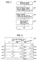
message receiving Process 2500 which is the process of the periodicalmessage receiving process 250 will be explained using Fig. 2. First, the periodicalmessage receiving Process 2500 reads out a received message which was taken from the control system network 20 (Process 2501). This is executed by calling out Receive Message () of the control systemnetwork communicating process 220, as mentioned above. - Next, the message read out is stored in the period/event message buffer 202 (Process 2502). Now, the construction of the period/
event message buffer 202 will be explained using Fig. 3. As explained above, a message has ID (identifier) attached thereto. The period/event message buffer 202 includes a messageID storing area 20210, a this-time-value (value of the most recent message) storingarea 20220 and a last-time-value (value of the message received most previously after the most recent message) storingarea 20230. Further, these areas are divided into storing areas per ID. That is, theID storing area 20210 comprises anarea 20211, anarea 20212, anarea 20213, etc. The this-time-value storing area 20220 comprises anarea 20221, anarea 20222, anarea 20223, etc. per respective ID. The last-time-value storing area 20230 also comprises anarea 20231, anarea 20232, anarea 20233, etc. per ID. For example, the message of ID2 is stored so that the value (2) of its ID is memorized in thearea 20211, the this-time-value (20) is memorized in thearea 20221 and the last-time-value (18) is memorized in thearea 20231. - In
Process 2502, the value of the message read out is stored in the storing area of the this-time-value corresponding to the ID of this message. For example, in the case of the message of which ID is 2, the value of the message read out is stored in thearea 20221. In the case of the message having ID of 6, the value of the message read out is stored in thearea 20222. - Lastly, a message value
change detecting process 2800 is started up (Process 2503). In starting up it, the message ID of the received message is given. - Next, the message value
change detecting process 2800 which is the process of the message valuechange detecting process 280 will be explained using Fig. 4. The message valuechange detecting process 280 is started up from the periodic message receiving process, as explained above. - The message value
change detecting process 2800, when started up, first reads out the message stored in the period/event message buffer 202 to check whether or not the this-time-value of the received message is deferent from the last-time-value thereof (Process 2801). For example, if in Fig. 3 the ID of the message is 2, both are different since its this-time value is 20 and its last-time-value is 18. If the ID of the message is 6, both are the same since its this-time-value is 6400 and its last-time-value is also 6400. - If the last-time-value and the this-time-value are different from each other, the event
message sending process 270 is started up (Process 2802), whereas if the last-time-value and the this-time-value are the same, the processing is completed without any additional process. - Next, an event
message sending process 2700 which is the program of the eventmessage sending process 270 will be explained by using Fig. 5. The eventmessage sending process 2700 is started up in case where the value of the message fetched from thecontrol system network is different from the last-time-value. - First, the event
message sending process 2700 reads out the this-time-value of the message sent from the period/event message buffer 202 (Process 2701). For example, in Fig. 3 if the message having its ID of 2 is intended to be sent, the this-tame-value 20 stored in thearea 20221 is read out. - Next, by calling up the information system
network communication process 230, the transmission of the message is effected (Process 2702). This can be executed by calling out Send Message (), as stated above. In this embodiment, the messages are transmitted by using the same ID both in the control system network and in the information system network. Although different IDs can be used in both of the control system and the information system, in this case it is needed to memorize the correspondence between the ID used in the control system and the ID used in the information system. - Lastly, the this-time-value of the periodical
event message buffer 202 is stored as the last-time-value (Process 2703). For example, in Fig. 3, in the case of the message having the ID of 2, the value which was stored in thearea 20221 is stored in thearea 20231. - The above-described explanation is the operation for transferring the message from the
control system network 20 handling the periodic message to theinformation system network 30 handling the event message. - An example of operation for message transfer from the
control system network 20 to theinformation system network 30 will be explained using Fig. 6. Fig. 6 shows that for the message having the ID of 2 in Fig. 3 the reception timing of the periodical message from thecontrol system network 20, the transmission timing of the event message to theinformation system network 30, and the change of the storingarea 20221 for the this-time-value of the message having the ID of 2 of the period/event message buffer. The figure shows the flow of time downwardly. - The periodical message is at a constant period, and received in the way of 20251, 20252, 20253, 20254, 20255. Incidentally, in this case, it is supposed that before the
periodic message 20251 is received, the this-time-value of the message is 15. The value of theperiodical message 20251 is 15, the values of 20252, 20253 and 20254 are 18 and the value of 20255 is 20. When theperiodical message 20252 is received, the this-time-value changes from 15 to 18, and at this timing theevent message 20261 having its value of 18 is transferred. Also, when theperiodical message 20255 is received, the this-time-value changes from 18 to 20, and at this timing theevent message 20262 having its value of 20 is transmitted. - As explained above, the message for the
control system network 20 which is received periodically, only at the time when its value is different from the value which was received at the last time, is transferred to theinformation system network 30. - Next, message transfer from the
information system network 30 handling the event message to thecontrol system network 20 handling the periodical message will be explained. In this embodiment, it is supposed that all of the messages of thecontrol system network 20 are the same in sending period. - The event
message receiving process 260 is executed as one task. This task is started up in response to the reception event of the message on the information system network by means of theOS 210. Since on theinformation system network 30 the message is delivered in response to an event, this process (task) is also started up periodically in response to this event. - The flow of an event
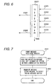
message receiving process 2600 which is the process of the eventmessage receiving process 260 will be explained using Fig. 7. The eventmessage receiving process 2600 first reads out the received message fetched from the information system network 30 (Process 2601). This is executed by calling out Receive Message () of the information systemnetwork communicating process 230, as explained above. - Next, the message read out is stored in the event/period message buffer 201 (Process 2602). Now, the construction of the event/
period message buffer 201 will be explained using Fig. 8. The event/period message buffer 201 has a message ID storing area 20110 and a value storing area 20120. Further, these areas are divided into storing areas per ID. That is, the ID storing area 20110 is comprised of an area 20111, an area 20112, an area 20113, etc. The value storing area 20120 is comprised of an area 20121, an area 20122, an area 20123, etc. In Fig. 8, for example, in the case of the message having the ID value of 1, the value of the message read out is stored in the area 20121. In the case of the message having the ID value of 5, the value of the message read out is stored in the area 20122. - Next, a periodical
message sending process 240 which is the process of the periodicalmessage sending process 240 will be explained by using Fig. 9. The periodicalmessage sending process 240 is started up periodically by theOS 210 in accordance with the transmission period of the message of the control system network. As mentioned above, in one embodiment of this invention, it is supposed that the transmission period of all of the messages of thecontrol system network 20 is the same. - The periodical message sending process 2400 first reads out the value of the message to be delivered from the event/period message buffer 201 (Process 2401). Incidentally, all of the messages to be sent are administrated with their IDs. For example, in Fig. 8, in case where the message having its ID of 1 has been registered as the message to be sent, the this-time-
value 100 stored in the area 20121 is read out. - Thereafter, the control system
network communicating process 220 is called out to perform the transmission of the message (Process 2402). This can be achieved by calling out Send Message () as mentioned above. In this embodiment, the messages are transferred with the same ID in both of the control system and the information system, as mentioned above. Although different IDs can be used in the control system and the information system, in this case it is needed to memorize the correspondence between the ID used in the control system and the ID used in the information system. - The above-mentioned process 2401 and process 2402 are repeated until the processes for all messages are completed (Process 2403).
- The above is the message transferring operation from the
information system network 30 handling the event message to thecontrol system network 20 handling the periodic message. - An example of the transferring operation from the
information system network 30 to thecontrol system network 20 will be explained using Fig. 10. Fig. 10 shows, for the message having the ID of 1 in Fig. 7, the reception timing of the event message from the information system network, the transmission timing of the periodical message to thecontrol system network 20, and the change of the storing area 20121 in the value of the message having the ID of 1 in the event/period message buffer. In the figure, the downward flow of time indicates the passage of time. - The event messages are received in the way of 20161, 20162 and 20163. The value of the event message 20161 is 80, the values of 20162 is 90, and the value of 20163 is 100. On the other hand, the periodical messages are at a constant period, and are delivered in the way of 20151, 20152, 20153, 20154 and 20155. As the value of the periodical message, the value in the storing area 20151 for the message value at the point of time of the delivery is used. Therefore, the values of the periodical messages 20151, 20152 and 20153 are 80, and the values of the periodic messages 20154 and 20155 are 100.
- Incidentally, although after the periodical message 20153 was delivered, the value changes to 90 by the reception of the event message 20162, this event message having the value of 90 is not delivered since before the next periodic message is delivered the value changes to 100 by the reception of the event message 20163.
- As mentioned above, the messages of the information system network as received periodically in response to events are delivered to the control system network periodically.
- An example of a distributed system for an automobile using the gateway of this embodiment is shown in Fig. 11. This distributed system has two networks, a
control system network 20 and aninformation system network 30, which are connected through thegateway 10 as explained above. - To the
control system network 20 thegateway 10 as well as an engine controlling unit 40 for controlling an engine and an ACC (Adaptive Cruise Control) controlling unit 50 for performing automobile travelling control to maintain the distance between a preceding car constant, are connected. Between the engine controlling unit, the ACC controlling unit and the gateway the information is exchanged by the periodical messages. - To the
information system network 30 thegateway 10 as well as a navigation system 60 for performing course guidance and an internet terminal 70 for connecting to the internet to gather information are connected. Between the navigation system, the internet terminal and the gateway the information is exchanged by the event massages. - With such system construction, it is possible to exchange the information between the navigation system and the ACC unit or between the navigation system and the engine controlling unit. For example, it is possible to realize the function of performing inter-car distance control within the range below the restricted speed by delivering course limited speed information from the navigation system to the ACC unit. Also, by delivering engine status information such as engine speed or the like from the engine controlling unit to the navigation system it is possible to observe the engine status on the screen of the navigation system.
- The above was the detailed explanation as to one embodiment of this invention.
- In accordance with one embodiment of this invention, in the distributed system having the information system network and control system network within an automobile there exists the effect that a periodical message suitable to exchange the information for control can be used in the control system network and an event massage suitable to exchange the information for information processing can be used in the information system network, and that the control system network and the information system network in the automobile can be connected effectively.
- Also, in accordance with one embodiment of this invention, the periodic message receiving process was started up in response to the received event of the message on the control system network. With it, it is possible to start up the receiving process as soon as the periodic massage reaches, and also to deliver the event message immediately upon the change of value. by this, the effect is provided that any time delay following the message transfer from the control system network to the information system network can be minimized.
- Also, in accordance with one embodiment of this application, both of the control system network and the information system network was arranged by using the DAM network. Thus, by using the same kind of network in both networks, the effect that it is possible to make the system construction simple is provided, Also, there exists the effect that in the hardware it is possible to use a micro-controller which houses the CPU, the memory and two CAN controllers, and whereby the gateway can be installed compactly.
- The
control network 20 according to one embodiment of this invention was constructed using the CAN, but a network such as SAE/J1850, TTP (Time-Triggered Protocol) or the like may be used. Also, in one embodiment of this invention, the CAN was used in the information system network, but instead a network such as D2B Optical, IDB (ITS DATA Bus), VAN (Vehicle Area Network) or the like may be used. It is possible to use different networks between the control system network and the information system network. Since these various networks can be used, the effect is provided that it is possible to cope with a wider range of automobile systems. Also, there exists the effect that by using a high speed network it is possible to realize a system with high performance. - In one embodiment of this invention, the network communication process according to the OSEK-COM specification was used in the control system
network communicating process 220 and the information systemnetwork communicating process 230. However, it is possible to use a control system network communicating process or information system network communicating process according to a specification such as IDB or the like. With this, the effect is provided that it is possible to apply it to a wider range of automobile systems. - In one embodiment of this invention, the transmission period of the control network was made constant regardless of the message, but it is possible to change the period per message. In this case, it is needed to memorize in the
memory 200 the correspondence between the ID and the transmission timing of the periodical message. TheOS 210 starts up the control systemnetwork communicating process 220 in conformity to the transmission timing of the periodical message, and transfers the ID of the message to be sent. The control systemnetwork communicating process 220, on the basis of the ID transferred from theOS 210, reads out the message of which ID agrees from the event/period message buffer, and performs the message transmitting process. Thus, the effect is provided that it is possible to set up the most appropriate transmission period per message and to use the network effectively. - In said one embodiment of this invention, the bi-directional message transfer was made between the control system network and the information system network. However, it may be modified to one directional transfer from the control system network to the information system network or from the information system network to the control system network. Thus, the effect is given that the exchange of information is limited so as thereby to improve security.
- In said one embodiment of this invention, the periodical message receiving process was started up in response to the reception event of the message on the control system network. However, it may be started up at the same period as the periodical message.
- Now, the case where the periodical message receiving process is started up at the same period, as the periodical message will be explained. In this case, the correspondence between the message ID to be received and the startup timing of the periodical message receiving process and the correspondence between the message ID to be sent and the startup timing of the periodical message sending process are stored in the
memory 200. TheOS 210 manages the startup timing of the periodical message receiving process and the startup timing of the periodical message sending process, and starts the periodicalmessage receiving process 250 and the periodicalmessage sending process 240. Also, theOS 210, when starting up the periodicalmessage sending process 240, delivers the periodical message ID to be sent. In response thereto, the periodical message sending process shown in Fig. 9 is carried out, and the message corresponding to the delivered ID is transmitted. Also, theOS 210, when starting up the periodicalmessage receiving process 250, delivers the periodical message ID to be received. In response thereto, the periodical message receiving process shown in Fig. 2 is executed, and the reception of the message corresponding to the delivered ID is performed. - Also, the periodic message receiving process may be performed as the same task as the periodical message sending process. By this, the effect is provided that it is possible to make the task construction simple.
- In said one embodiment of this invention, the OS was used and the task was started up by the function of the OS. However, instead it is possible to start up and execute, without the OS, the periodical message receiving process by interrupt from the control system network controller, the event message receiving process by interrupt from the information system network controller and the periodical message sending process by interrupt from a timer. Thus, the effect is provided that the OS becomes unnecessary and the reduction of cost can be achieved.
- In said one embodiment of this invention, one control system network and one information system network were connected. So, the
networks network controllers network drivers 50 and 700 corresponding to the control system network and information system network, respectively, were provided. However, instead, it is possible to connect a plurality of control system networks and a plurality of information system networks. To this end, it is needed to provide the control system network controllers, the control system network drivers and the control system networks corresponding to the number of the plurality of control system networks, respectively. Further, in the control system network communicating process 220 a function for performing allocation to this plurality of control system networks on the basis of the network IDS is provided. Also, the information system network controllers, the information system network drivers and the information system networks, the respective numbers corresponding to the number of the plurality of information system networks are provided, and a function is provided for performing allocation to these plurality of information system networks. By this, the effect is provided that it can cope with a large-scale system. - In said control system according to one embodiment of this invention, only the periodical message was used. However, instead, it is possible to use mixed event massage and periodical message in the control system network. In this case, at the time of the transfer from the control system network to the information system network, the periodical message is transferred after it was converted to the event message as in the one embodiment of the invention, whereas the event message is transfer as it is. Also, in the case of the transfer from the information system network to the control system network, there are the methods for transforming the event message into the periodical message as in the one embodiment of this invention, and for transferring it as it is. It is possible to properly use them depending upon the message. By this, the effect is provided that it is possible to use the event massage also in the control system, and in case where information having lesser changes is exchanged, it is possible to reduce the load of the network.
- In the information system network according to said one embodiment of this invention, only the event message was used. However, instead, it is possible to use mixed event massage and periodical message in the information system network. In this case, when the transfer from the information system network to the control system network is carried out, the event message is transferred after is was transformed into the periodical message as in the case of the one embodiment of this invention, whereas the periodical message is trans as it is. In the case of the transfer from control system network to the information system network, there are the methods for transforming the periodical message into the event message as in the one embodiment of this invention, and for transferring it as the periodical message is. It is possible to properly use them depending upon the message. By this, the effect is provided that it is possible to use the periodical message also in the information system, and to improve real-time capacity as to multi-media information such as an image, and an audio.
- In the distributed system according to said one embodiment of this invention, the control system network and the information system network were connected through the gateway which is of the type of an independent arrangement, but the gateway function may be incorporated within the controlling unit of the control system. An embodiment for this is shown in Fig. 12. In this embodiment, there are a
control system network 20 and aninformation system network 30. To thecontrol system network 20, an engine controlling unit 40 and an ACC control unit 50 are connected. Also, to theinformation system network 30, the engine controlling unit 40 and a navigation system 60 are connected. In this embodiment, a gateway function 410 is placed within the engine controlling unit 40, to cause the engine controlling unit 40 to have the gateway function. The gateway function 410 can be realized in the similar way to the gateway in one embodiment of this invention. By this, the effect is provided that there is no need to use an independent gateway, and therefore it is possible to reduce the cost. - In said one embodiment of this invention, the function of the gateway was realized by means of software, but it is possible to achieve the same function by means of hardware. By this, the effect can be obtained that the system is speeded up.
- In said one embodiment of this invention, the control system network for transmitting the periodical message and the information system network for transmitting the event message were connected, but with a network for transmitting the periodical message and a network for transmitting the event message, they are not limited to the control system network and the information system network, respectively. For example, they may be a power train system control network using the periodic message and a body system control network using the event message, respectively. Also, they are not limited to the use in an automobile. For example, in the network handling the periodical message and the network handling the event message they are applicable to many systems such as an FA (Factory Automation) system, an electric power system, a railroad system, a steel system and the like. By this, there occurs the effect that in a distributed system having various networks a high efficiency gateway can be obtained.
- This invention can be applied to a field such as industrial machinery, an electric power, a railroad, steel, an automobile or the like in which a plurality of kinds of networks are interconnected.
Claims (6)
- A gateway comprising: periodical message receiving means for receiving a periodic message delivered periodically onto one network for reading in data; memory means for storing the data of said periodic message; message value change detecting means for detecting the change of the value of the data stored in said memory means; and event message sending means for delivering the data stored in said memory means as a message on another network when said message value change detecting means detects a change of the value of the data.
- A gateway comprising: event massage receiving means for receiving an event massage delivered onto one network in response to an event or demand for reading in data; memory means for storing the data of said event massage; and periodical message sending means for delivering periodically the data stored in said memory means as a message on a different network.
- A distributed system comprising:a first network to which at least one device for performing periodically the sending or receiving of a message is connected;a second network to which at least one device for performing the sending or receiving of a message in response to an event or demand; anda gateway connected to said first and second networks, said gateway having periodical message receiving means for receiving messages which said first network sends periodically, memory means for storing the message received by said periodical message receiving means, message value change detecting means for detecting the change of the value of the data included in the message stored in said memory means, and event message sending means for producing a message from the data stored in said memory means when said message value change detecting means detects a change of the value of the data, and for delivering the produced message to said second network.
- A distributed system as claimed in claim 3, wherein said device for performing periodically the sending or receiving messages is an engine controlling device or an ACC control unit, and said device for performing the sending or receiving of messages in response to an event or demand is an navigation system or an internet terminal.
- A distributed system comprising:a first network on which a message generated at a predetermined time interval resides;s second network on which a message generated in response to an event or demand resides; anda gateway connected to said first and second network and having a memory part and a processing part;said processing part of said gateway causing to memorize in said memory part the message generated by said first network at a predetermined time interval, detecting a change of the value of the data included in said memorized message, producing a message from the data memorized in said memory part when a change of the value of the data is detected, and delivering said produced message to said second network.
- A distributed system as claimed in claim 5, wherein said processing part causes to memorize in said memory part the message generated in response to an event or demand from said second network, and delivers said memorized message to said first network at a predetermined time interval.
Applications Claiming Priority (1)
| Application Number | Priority Date | Filing Date | Title |
|---|---|---|---|
| PCT/JP1999/007042 WO2001045329A1 (en) | 1999-12-15 | 1999-12-15 | Gateway and distributed system using the gateway |
Publications (3)
| Publication Number | Publication Date |
|---|---|
| EP1244252A1 true EP1244252A1 (en) | 2002-09-25 |
| EP1244252A4 EP1244252A4 (en) | 2005-07-13 |
| EP1244252B1 EP1244252B1 (en) | 2009-03-25 |
Family
ID=14237576
Family Applications (1)
| Application Number | Title | Priority Date | Filing Date |
|---|---|---|---|
| EP99959826A Expired - Lifetime EP1244252B1 (en) | 1999-12-15 | 1999-12-15 | Gateway and distributed system using the gateway |
Country Status (5)
| Country | Link |
|---|---|
| EP (1) | EP1244252B1 (en) |
| JP (1) | JP3736460B2 (en) |
| KR (1) | KR100372982B1 (en) |
| DE (1) | DE69940645D1 (en) |
| WO (1) | WO2001045329A1 (en) |
Cited By (3)
| Publication number | Priority date | Publication date | Assignee | Title |
|---|---|---|---|---|
| FR2866172A1 (en) * | 2004-02-10 | 2005-08-12 | Renault Sas | Data transmission gateway for controller area network of motor vehicle, has transmission unit for transmitting simulated data stream that is identical to stream emitted by receiver and transmitted by gateway |
| EP1779160A2 (en) * | 2004-07-30 | 2007-05-02 | Fisher-Rosemount Systems, Inc. | System and method for preventing transmission during message reception |
| US8693346B2 (en) | 2007-02-07 | 2014-04-08 | Hitachi, Ltd. | On-vehicle gateway device, method for controlling an on-vehicle gateway device, connection device and connection control method |
Families Citing this family (7)
| Publication number | Priority date | Publication date | Assignee | Title |
|---|---|---|---|---|
| EP1624620B1 (en) * | 2004-08-05 | 2010-05-05 | Robert Bosch Gmbh | FlexRay communication controller |
| JP4525973B2 (en) * | 2004-11-10 | 2010-08-18 | Udトラックス株式会社 | Vehicle data processing system |
| US7733841B2 (en) * | 2005-05-10 | 2010-06-08 | Continental Automotive Systems, Inc. | Vehicle network with time slotted access and method |
| JP4959484B2 (en) * | 2007-09-18 | 2012-06-20 | 株式会社オートネットワーク技術研究所 | Relay connection unit |
| KR100917338B1 (en) * | 2007-09-21 | 2009-10-05 | 쌍용자동차 주식회사 | Forwarding method of a can message for a car network communication |
| JP2011131762A (en) * | 2009-12-25 | 2011-07-07 | Hitachi Automotive Systems Ltd | Control device for data relay, and vehicle control system |
| JP5337861B2 (en) * | 2011-12-01 | 2013-11-06 | 日立オートモティブシステムズ株式会社 | In-vehicle gateway device |
Citations (3)
| Publication number | Priority date | Publication date | Assignee | Title |
|---|---|---|---|---|
| US5365512A (en) * | 1993-07-02 | 1994-11-15 | Ericsson Ge Mobile Communications Inc. | Multisite trunked RF communication system with reliable control messaging network |
| US5475683A (en) * | 1994-01-07 | 1995-12-12 | Ericsson Ge Mobile Communications Inc. | Method and apparatus for permitting radio unit roaming between trunked RF transmission sites over a wide area that encompasses plural multisite networks |
| WO1997024842A2 (en) * | 1995-12-29 | 1997-07-10 | Mci Communications Corporation | Method and system for resilient frame relay network interconnection |
Family Cites Families (6)
| Publication number | Priority date | Publication date | Assignee | Title |
|---|---|---|---|---|
| US5332708A (en) * | 1992-11-23 | 1994-07-26 | Phillips Petroleum Company | Catalyst compositions and catalytic processes |
| US5923673A (en) * | 1997-02-13 | 1999-07-13 | Sony Corporation | IEEE 1394 data/protocol analyzer |
| JPH1124710A (en) * | 1997-07-01 | 1999-01-29 | Toshiba Corp | Distributed control system |
| JPH11338837A (en) * | 1998-05-21 | 1999-12-10 | Toshiba Corp | Data collection system |
| KR20000031522A (en) * | 1998-11-06 | 2000-06-05 | 윤종용 | Method for forming information data tree of equipment management using communication management network and method for processing alarm using the same |
| KR100281554B1 (en) * | 1998-12-15 | 2001-03-02 | 정선종 | Gateway system and interworking method for interworking between telecommunication management network management agent and integrated service / network management system |
-
1999
- 1999-12-15 KR KR10-2001-7003569A patent/KR100372982B1/en not_active IP Right Cessation
- 1999-12-15 JP JP2001546098A patent/JP3736460B2/en not_active Expired - Fee Related
- 1999-12-15 DE DE69940645T patent/DE69940645D1/en not_active Expired - Fee Related
- 1999-12-15 EP EP99959826A patent/EP1244252B1/en not_active Expired - Lifetime
- 1999-12-15 WO PCT/JP1999/007042 patent/WO2001045329A1/en active Search and Examination
Patent Citations (3)
| Publication number | Priority date | Publication date | Assignee | Title |
|---|---|---|---|---|
| US5365512A (en) * | 1993-07-02 | 1994-11-15 | Ericsson Ge Mobile Communications Inc. | Multisite trunked RF communication system with reliable control messaging network |
| US5475683A (en) * | 1994-01-07 | 1995-12-12 | Ericsson Ge Mobile Communications Inc. | Method and apparatus for permitting radio unit roaming between trunked RF transmission sites over a wide area that encompasses plural multisite networks |
| WO1997024842A2 (en) * | 1995-12-29 | 1997-07-10 | Mci Communications Corporation | Method and system for resilient frame relay network interconnection |
Non-Patent Citations (1)
| Title |
|---|
| See also references of WO0145329A1 * |
Cited By (5)
| Publication number | Priority date | Publication date | Assignee | Title |
|---|---|---|---|---|
| FR2866172A1 (en) * | 2004-02-10 | 2005-08-12 | Renault Sas | Data transmission gateway for controller area network of motor vehicle, has transmission unit for transmitting simulated data stream that is identical to stream emitted by receiver and transmitted by gateway |
| WO2005079010A1 (en) * | 2004-02-10 | 2005-08-25 | Renault Technocentre | Gateway and data transmission system for a motor vehicle diagnostic network |
| EP1779160A2 (en) * | 2004-07-30 | 2007-05-02 | Fisher-Rosemount Systems, Inc. | System and method for preventing transmission during message reception |
| EP1779160A4 (en) * | 2004-07-30 | 2010-07-21 | Fisher Rosemount Systems Inc | System and method for preventing transmission during message reception |
| US8693346B2 (en) | 2007-02-07 | 2014-04-08 | Hitachi, Ltd. | On-vehicle gateway device, method for controlling an on-vehicle gateway device, connection device and connection control method |
Also Published As
| Publication number | Publication date |
|---|---|
| DE69940645D1 (en) | 2009-05-07 |
| WO2001045329A1 (en) | 2001-06-21 |
| KR20010111088A (en) | 2001-12-15 |
| EP1244252A4 (en) | 2005-07-13 |
| JP3736460B2 (en) | 2006-01-18 |
| EP1244252B1 (en) | 2009-03-25 |
| KR100372982B1 (en) | 2003-02-20 |
Similar Documents
| Publication | Publication Date | Title |
|---|---|---|
| US7046638B1 (en) | Wireless access to closed embedded networks | |
| US6360145B1 (en) | Vehicle platform-portable controller | |
| WO2014057643A1 (en) | Relay device | |
| EP1244252A1 (en) | Gateway and distributed system using the gateway | |
| US20180141439A1 (en) | Onboard vehicle communication system | |
| CN104718725A (en) | Relay device | |
| US11233736B2 (en) | Vehicle gateway and method of controlling the same | |
| WO2010004765A1 (en) | Relay apparatuses, communication system, and communication method | |
| US7836233B2 (en) | Multi-processor system | |
| CN112583691B (en) | Relay device and external device | |
| EP0869039A3 (en) | Vehicle communication control apparatus and method | |
| EP1209878A2 (en) | Motor vehicle communication protocol with automatic device address assignment | |
| CN110731089A (en) | Data transmission device and data transmission method for vehicle | |
| JP7140011B2 (en) | Gateway device | |
| JP2020022019A (en) | Vehicle system | |
| JP5601306B2 (en) | Vehicle network communication management device | |
| EP1050826A1 (en) | Method for operating a communication system on a serial bus | |
| CN106257871B (en) | Method for configuring communication of control unit and control unit | |
| JP2002204243A (en) | Multiplex communication device for vehicle | |
| CN110086502A (en) | Vehicle-mounted relay, relay and method, information processing unit and system | |
| JP2024035432A (en) | Communication device | |
| EP1217531B1 (en) | Method of providing communication in distributed systems | |
| JP3088199B2 (en) | Multiplex communication device | |
| CN117413494A (en) | Method for configuring a plurality of gateway controllers of a vehicle, computer readable medium, system and vehicle | |
| JPH11112536A (en) | Vehicle multiplex communication equipment |
Legal Events
| Date | Code | Title | Description |
|---|---|---|---|
| PUAI | Public reference made under article 153(3) epc to a published international application that has entered the european phase |
Free format text: ORIGINAL CODE: 0009012 |
|
| 17P | Request for examination filed |
Effective date: 20010809 |
|
| AK | Designated contracting states |
Kind code of ref document: A1 Designated state(s): AT BE CH CY DE DK ES FI FR GB GR IE IT LI LU MC NL PT SE |
|
| RBV | Designated contracting states (corrected) |
Designated state(s): DE FR GB |
|
| A4 | Supplementary search report drawn up and despatched |
Effective date: 20050527 |
|
| RIC1 | Information provided on ipc code assigned before grant |
Ipc: 7H 04L 12/66 A |
|
| 17Q | First examination report despatched |
Effective date: 20071217 |
|
| GRAP | Despatch of communication of intention to grant a patent |
Free format text: ORIGINAL CODE: EPIDOSNIGR1 |
|
| GRAS | Grant fee paid |
Free format text: ORIGINAL CODE: EPIDOSNIGR3 |
|
| GRAC | Information related to communication of intention to grant a patent modified |
Free format text: ORIGINAL CODE: EPIDOSCIGR1 |
|
| RIN1 | Information on inventor provided before grant (corrected) |
Inventor name: NAGAURA, WATARU,C/O HITACHI RESEARCH LABORATORY Inventor name: YOKOYAMA, TAKANORI,C/O HITACHI RESEARCH LABORATORY |
|
| RAP1 | Party data changed (applicant data changed or rights of an application transferred) |
Owner name: HITACHI, LTD. |
|
| GRAA | (expected) grant |
Free format text: ORIGINAL CODE: 0009210 |
|
| AK | Designated contracting states |
Kind code of ref document: B1 Designated state(s): DE FR GB |
|
| REG | Reference to a national code |
Ref country code: GB Ref legal event code: FG4D |
|
| REF | Corresponds to: |
Ref document number: 69940645 Country of ref document: DE Date of ref document: 20090507 Kind code of ref document: P |
|
| PLBE | No opposition filed within time limit |
Free format text: ORIGINAL CODE: 0009261 |
|
| STAA | Information on the status of an ep patent application or granted ep patent |
Free format text: STATUS: NO OPPOSITION FILED WITHIN TIME LIMIT |
|
| 26N | No opposition filed |
Effective date: 20091229 |
|
| GBPC | Gb: european patent ceased through non-payment of renewal fee |
Effective date: 20091215 |
|
| REG | Reference to a national code |
Ref country code: FR Ref legal event code: ST Effective date: 20100831 |
|
| PG25 | Lapsed in a contracting state [announced via postgrant information from national office to epo] |
Ref country code: FR Free format text: LAPSE BECAUSE OF NON-PAYMENT OF DUE FEES Effective date: 20091231 |
|
| PG25 | Lapsed in a contracting state [announced via postgrant information from national office to epo] |
Ref country code: DE Free format text: LAPSE BECAUSE OF NON-PAYMENT OF DUE FEES Effective date: 20100701 |
|
| PG25 | Lapsed in a contracting state [announced via postgrant information from national office to epo] |
Ref country code: GB Free format text: LAPSE BECAUSE OF NON-PAYMENT OF DUE FEES Effective date: 20091215 |