EP1245930A2 - Automatic integrated mechanical and electrical angular motion detector test system - Google Patents
Automatic integrated mechanical and electrical angular motion detector test system Download PDFInfo
- Publication number
- EP1245930A2 EP1245930A2 EP02252219A EP02252219A EP1245930A2 EP 1245930 A2 EP1245930 A2 EP 1245930A2 EP 02252219 A EP02252219 A EP 02252219A EP 02252219 A EP02252219 A EP 02252219A EP 1245930 A2 EP1245930 A2 EP 1245930A2
- Authority
- EP
- European Patent Office
- Prior art keywords
- motion detector
- angular motion
- test system
- test
- motor
- Prior art date
- Legal status (The legal status is an assumption and is not a legal conclusion. Google has not performed a legal analysis and makes no representation as to the accuracy of the status listed.)
- Withdrawn
Links
Images


Classifications
-
- G—PHYSICS
- G01—MEASURING; TESTING
- G01C—MEASURING DISTANCES, LEVELS OR BEARINGS; SURVEYING; NAVIGATION; GYROSCOPIC INSTRUMENTS; PHOTOGRAMMETRY OR VIDEOGRAMMETRY
- G01C25/00—Manufacturing, calibrating, cleaning, or repairing instruments or devices referred to in the other groups of this subclass
- G01C25/005—Manufacturing, calibrating, cleaning, or repairing instruments or devices referred to in the other groups of this subclass initial alignment, calibration or starting-up of inertial devices
Landscapes
- Engineering & Computer Science (AREA)
- Manufacturing & Machinery (AREA)
- Physics & Mathematics (AREA)
- General Physics & Mathematics (AREA)
- Radar, Positioning & Navigation (AREA)
- Remote Sensing (AREA)
- Gyroscopes (AREA)
- Testing Or Measuring Of Semiconductors Or The Like (AREA)
- Testing Of Individual Semiconductor Devices (AREA)
Abstract
Description
- This invention relates to an automatic integrated mechanical and electrical angular motion detector test system.
- Conventional integrated circuit (IC) device handlers automatically feed IC devices to a contactor which makes electrical interconnection between the IC device and a tester. After the tester runs a series of tests on that IC device, the device is removed from the contactor and output from the handler to one of a number of bins depending on whether it passed the test or failed it. There may be a number of future bins for classifying different types of failures. These systems have high throughput typically from 500-8000 devices/hour with little or no human intervention.
- Separately, gyroscope testers for conventional strategic and tactical gyroscopes typically employ a large rate table with fixtures including temperature chambers for testing a gyroscope. The gyroscopes are manually placed and installed before testing and are manually removed after testing. The testing involves performing electrical testing while the gyroscope is being rotated in order to insure proper performance under actual operating conditions. A typical test time is several minutes to a few hours per gyroscope. These gyroscopes are relatively heavy and large, e.g. strategic gyroscopes - two inch diameter, four inches long; tactical gyroscopes - one inch diameter, two inches long. Typically a number of these gyroscopes are tested at one time to produce even a reasonable throughput. The tables are large and powerful to obtain the necessary rotational speed and accuracy with the gyroscopes loaded on board. Further, these tables must be precisely controlled in order to insure the reliability of the test data of these precision gyroscopes. The table must rotate at significant speed for a substantial period of time with very little fluctuation in the rotational speed.
- More recently, micromachining techniques have produced extremely small, lightweight micromachined gyroscopes. See U.S. Patent No. 6,122,961. These gyroscopes, too, must be tested. However, the more commercial nature of their market requires precision testing but with much higher throughput and less human intervention. The rate tables so appropriate for the larger gyroscopes are excessive and too slow for processing these micromachined gyroscopes.
- It is therefore an object of this invention to provide an improved automatic, integrated mechanical and electrical angular motion detector test system.
- It is a further object of this invention to provide such an angular motion detector test system which is smaller, lighter, and simpler.
- It is a further object of this invention to provide such an angular motion detector test system which has a higher throughput.
- It is a further object of this invention to provide such an angular motion detector test system which is faster, more efficient, more accurate and more reliable.
- It is a further object of this invention to provide such an angular motion detector test system which measures the electrical parameters of a gyroscope while it is being rotated to obtain performance data under various operating conditions.
- It is a further object of this invention to provide such an angular motion detector test system which enables the mechanical and electrical testing of an IC gyroscope.
- It is a further object of this invention to provide such an angular motion detector test system which provides a sinusoidal drive to rotate the gyroscope under test.
- The invention results from the realization that a smaller, simpler, lightweight, automated, angular motion detector test system with high throughput can be achieved using a test fixture for holding a device to be tested, a handler for feeding devices to be tested to the test fixture, rotating the test fixture with a device to be tested and electrically testing the device while it is being rotated, and the further realization that micromachined angular motion detectors can be handled and fed to the test fixture as common IC's and then rotated in a stepwise fashion or by oscillation as with a galvanometer to obtain performance data from the electrical circuits of the device while it is being rotated.
- This invention features an automatic integrated mechanical and electrical angular motion detector test system. There is a test fixture for holding an angular motion detector to be mechanically and electrically tested and a handler subsystem for feeding an angular motion detector to the test fixture. A motor has a rotatable shaft attached to the test fixture for rotating it and the angular motion detector that it holds and an electrical tester tests the angular motion detector while it is rotating.
- In a preferred embodiment the test fixture may include a seat for supporting the angular motion detector in the test fixture. There may be clamp for urging an angular motion detector against the seat. There may be a vacuum chuck for holding and sensing the presence of an angular motion detector to be tested. There may be a contactor having at least one set of gripping contacts for engaging an angular motion to be tested. The clamp may include a lever and an actuator for driving the lever to operate the clamp. The contactor may include a lever and an actuator for driving the lever to operate the gripping contacts. The motor may include an oscillator motor. The motor may provide a sinusoidal output motion to the test fixture. The motor may include a stepper motor or galvanometer. The angular motion detector may be an angular accelerometer or a gyroscope. The gyroscope may be an integrated circuit chip and it may be micromachined.
- Other objects, features and advantages will occur to those skilled in the art from the following description of a preferred embodiment and the accompanying drawings, in which:
- Fig. 1 is a schematic three dimensional block diagram of an angular motion detector test system according to this invention;
- Fig. 2 is a block diagram of portions of the system of Fig. I;
- Fig. 3 is a diagrammatic three dimensional partially broken away view from the upper right of the test fixture of Figs. 1 and 2 according to this invention;
- Fig. 4 is a view similar to Fig. 3 but viewed from the lower left;
- Fig. 5 is an enlarged more detailed three dimensional view from the upper right of the test fixture of Fig. 3;
- Fig. 6 is an enlarged more detailed view from the right rear of the test fixture of Figs. 3, 4, and 5;
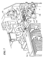
- Fig. 7 is a view similar to Fig. 6 showing the actuator components;
- Fig. 8 is a functional block diagram of the system according to this invention; and
- Figs. 9, 10, and 11 illustrate the galvanometer, stepper motor and torsional vibrator and their wave forms, respectively.
-
- There is shown in Fig. 1 an angular motion
detector test system 10 according to this invention including a test fixture contained within athermal housing 14 and having amotor 16.Test head 18 is interconnected with the device under test (DUT) bycable 20 andtest head 18 is in turn connected toelectrical tester 22 bycable 24. Amanipulator 26 such as made by Intest Corporation may be used to positiontest head 18 to accommodate thevarious handlers 28 that may be used with the system. In this particular case, the handler is an ASECO model S130 handler.Handler 28 receives micromachined integrated circuit angularmotion detector chips Computer 38 can be used to control the entire system and to interface with a local area network or larger network. - A similar handler system and test device for translational motion with respect to accelerometers is disclosed in U.S. Patent No. 5,895,858 Integrated Accelerometer Test System, Malone et al. Issued April 20, 1999 to the same assignee and is incorporated herein by reference in its entirety.
- In operation, each
integrated circuit chip handler 28 to test fixture 42 (Fig. 5) where it is rotated inthermal housing 14 by means ofgalvanometer motor 16 while simultaneously being electrically tested bytest head 18 throughcable 20.Galvanometer motor 16 may be a model 6900 scanner motor made by Cambridge Technology Inc.Handler 28 takes an individualintegrated circuit chip 44 and places it on test fixture 12 (Fig. 3) and more specifically on to thecontactor 42. - Angular motion
detector test system 10 of the subject invention may be used to test angular motion detectors such as angular accelerometers and gyroscopes. For simplicity, the following description refers to gyroscopes. Angular accelerometers would be tested in the same manner as described with respect to gyroscopes. -
Galvanometer motor 16 may actually includegalvanometer 16a, Fig. 2, andgalvanometer control circuit 16b.Galvanometer 16a has ashaft 40 which rotatescontactor 42 that carries the device under test (DUT) 44.Manipulator 26 andcomputer 38 have been omitted from Fig. 2. Theperformance board 50 and device undertest board 52 which are assembled to testhead 18 have been broken out separately in Fig. 2. -
Galvanometer shaft 40, Figs. 2 and 5, are connected by acoupler 60 by means ofshaft 62 andpillow block 64 tocontactor 42.Contactor 42 includes a mountingsection 70 and avacuum chuck 72. Vacuum applied throughhose 74 to chuck 72 is used to give an indication that an integrated circuit gyroscope chip is truly in place and ready for testing. Mountingsection 70 includes theseat 76 which receives the bottom edge of the integrated circuit gyroscope chip and aclamp 78 which is operated byclamp lever 80 to hold the upper edge of the integrated circuit gyroscope againstseat 76. Side levers 82, Fig. 3 and 84, Fig. 4 are spring loaded to press theirrespective contact elements 86, Fig. 3, and 88, Fig. 4, inwardly to grip the contacts of the micromachined integratedcircuit gyroscope chip 44, Fig. 4, when it is in place on mountingsection 70. Electrical testing is accomplished throughinterface board 90 which interconnects with thecontact elements wires 92 which eventually form intocable 20 as shown in Figs. 1 and 2. - The ends 94 of
contacts 86 that connect to interfaceboard 90 are shown in more detail in Fig. 5 where the side levers 82 and 84 as well as the clamp lever have been eliminated for clarity.Contacts 88 have similar ends (not shown) on the other side which also interconnect withinterface board 90. Also shown in Fig. 5 is a cutaway ofdrive shaft 62 showing itscentral bore 96 through which the vacuum is applied tovacuum chuck 72, Fig. 3. The vacuum is supplied throughvacuum line 74, Fig. 5 from avacuum source 98 and anindicator 100 may be used to show when a vacuum is being pulled indicating when an integratedcircuit gyroscope chip 44 is truly in place oncontactor 42. Fig. 5 also depicts a broken away view ofpillow block 64 showing itsinternal bearing assemblies Coupling 60 is also depicted in a sectional view showing the connection ofdrive shaft 62 andgalvanometer shaft 40. -
Levers respective contacts circuit gyroscope chip 44 in place on mountingsection 70. This is done by means ofsprings spring block 109, Fig. 6 which urge the rearward ends 118, 120 oflevers spring 122 which keeps clamp lever biased up at itsrearward end 124 so that its forward end is normally urged downward to grip an integratedcircuit gyroscope chip 44 in place againstseat 76. Also shown in Fig. 6 is a portion of the ends 94' ofterminals 88 which engage withinterface board 90. - The springs are opposed to, and the
various levers pneumatic actuator 130, Fig. 7, which movesclamp lever 80 against the force ofspring 122 to openclamp 78 and allow the integrated circuit gyroscope chip to be mounted. Likewise,pneumatic actuators springs contacts circuit gyroscope chip 44 to be positioned at mountingsection 70. The juxtaposition ofwires 92 andcable 20 which is formed fromwires 92 is also shown in Fig. 7. -
Tester 22, Fig. 8, may include a general purpose interface bus (GPIP),control block 150, and avision system 152. The vision system may include aTV camera 154 inside of thehandler 28 or close to it so that it can see and identify each integrated circuit gyroscope chip as it is being tested and the test result can be coordinated with the specific device for binning.Vision system 152 may also include amonitor 156 so that an operator can see exactly what is occurring and what piece is under test. Awaveform generator 158 generates a sine wave which is used by the galvanometercontrol power amplifier 16b to drivegalvanometer motor 16a with a smooth sinusoidal motion. Areference power supply 160powers reference sensor 162 and awaveform digitizer 164 receives the signal from the device undertest 44 through switchingcircuit 166 which may be a simple switching circuit if asingle handler 28 is used or maybe a multiplex switching system if a multisite handler having n sites is used. A digital/analog stimulus andmeasurement circuit 168 is used to provide the test signals to the device under test, the integratedcircuit gyroscope chip 44, and to receive the outputs from that system as it is rotated smoothly, sinusoidally bygalvanometer motor 16a.Tester 22 also includes a device under test (DUT)power supply 170 for powering integratedcircuit gyroscope chip 44 and aposition control circuit 171 which receives the output from position sensor 172 and 174 and delivers it to the digital/analog stimulus andmeasurement circuit 168 so that the electrical test signals can be coordinated with the rotary position of the device under test at any moment. - The
galvanometer motor 16a of this invention provides a smoothsinusoidal motion 180, Fig. 9, in response to asinusoidal input signal 182. This is not the case for other devices, for example,stepper motor 184, Fig. 10, when provided with asinusoidal input signal 186 provides a steppedoutput motion 188 in which the steep slopes of the vertical sides of the steps can overload the amplifier and introduce errors into the signal. The situation is equally undesirable if conventionaltorsional vibrators 190, Fig. 11, are used. There, asinusoidal input 192 results in amotion 194 that has significant harmonic distortion that will introduce significant errors into the test. - Although specific features of the invention are shown in some drawings and not in others, this is for convenience only as each feature may be combined with any or all of the other features in accordance with the invention. The words "including", "comprising", "having", and "with" as used herein are to be interpreted broadly and comprehensively and are not limited to any physical interconnection. Moreover, any embodiments disclosed in the subject application are not to be taken as the only possible embodiments.
- Other embodiments will occur to those skilled in the art and are within the following claims:
Claims (15)
- An automatic, integrated mechanical and electrical angular motion detector test system comprising:a test fixture for holding an angular motion detector to be mechanically and electrically tested;a handler subsystem for feeding an angular motion detector to said test fixture;a motor having a rotatable shaft attached to said test fixture for rotating it and the angular motion detector it holds; andan electrical tester for testing said angular motion detector while it is rotating.
- The test system of claim 1 in which said test fixture includes a seat for supporting said angular motion detector in said test fixture.
- The test system of claim 2 in which said text fixture includes a clamp for urging said angular motion detector against said seat.
- The test system of claim 1 in which said test fixture includes a vacuum chuck for sensing the presence of an angular motion detector to be tested.
- The test system of claim 1 in which said test fixture includes a contactor having at least one set of gripping contacts for engaging an angular motion detector to be tested.
- The test system of claim 3 in which said clamp includes a lever and an actuator for driving said lever to operate said clamp.
- The test system of claim 5 in which said contactor includes a lever and an actuator for driving said lever to operate said gripping contacts.
- The test system of claim 1 in which said motor includes an oscillator motor.
- The test system of claim 8 in which said motor produces a sinusoidal output motion to said test fixture.
- The test system of claim 1 in which said motor includes a stepper motor.
- The test system of claim 1 in which said motor includes a galvanometer.
- The test system of claim 1 in which said angular motion detector is a gyroscope.
- The test system of claim 12 in which said gyroscope is an integrated circuit chip gyroscope.
- The test system of claim 12 in which said gyroscope is a micromachined integrated circuit chip gyroscope.
- The test system of claim 1 in which said angular motion detector is an angular accelerometer.
Applications Claiming Priority (2)
| Application Number | Priority Date | Filing Date | Title |
|---|---|---|---|
| US09/822,117 US6640610B2 (en) | 2001-03-30 | 2001-03-30 | Automatic integrated mechanical and electrical angular motion detector test system |
| US822117 | 2001-03-30 |
Publications (2)
| Publication Number | Publication Date |
|---|---|
| EP1245930A2 true EP1245930A2 (en) | 2002-10-02 |
| EP1245930A3 EP1245930A3 (en) | 2006-02-01 |
Family
ID=25235186
Family Applications (1)
| Application Number | Title | Priority Date | Filing Date |
|---|---|---|---|
| EP02252219A Withdrawn EP1245930A3 (en) | 2001-03-30 | 2002-03-27 | Automatic integrated mechanical and electrical angular motion detector test system |
Country Status (3)
| Country | Link |
|---|---|
| US (1) | US6640610B2 (en) |
| EP (1) | EP1245930A3 (en) |
| JP (1) | JP3574437B2 (en) |
Families Citing this family (11)
| Publication number | Priority date | Publication date | Assignee | Title |
|---|---|---|---|---|
| MY138984A (en) * | 2000-03-01 | 2009-08-28 | Intest Corp | Vertical counter balanced test head manipulator |
| TWI339737B (en) * | 2005-04-27 | 2011-04-01 | Aehr Test Systems | Contactor assembly, cartridge, and apparatus and method for testing integrated circuit of device |
| CN100390543C (en) * | 2005-06-08 | 2008-05-28 | 大连理工大学 | High-load micro-mechanism dynamic characteristic testing apparatus |
| JP4675831B2 (en) * | 2006-06-02 | 2011-04-27 | Okiセミコンダクタ株式会社 | Triaxial acceleration sensor and method for inspecting triaxial acceleration sensor |
| US7800382B2 (en) | 2007-12-19 | 2010-09-21 | AEHR Test Ststems | System for testing an integrated circuit of a device and its method of use |
| TWI403721B (en) * | 2009-02-20 | 2013-08-01 | King Yuan Electronics Co Ltd | Rotating test module and test system thereof |
| TWI394949B (en) * | 2009-02-20 | 2013-05-01 | King Yuan Electronics Co Ltd | Dynamic test apparatus and method |
| TWI394950B (en) * | 2010-02-12 | 2013-05-01 | King Yuan Electronics Co Ltd | Rotary three-dimensional dynamic testing equipment |
| KR20230021177A (en) | 2017-03-03 | 2023-02-13 | 에어 테스트 시스템즈 | Electronics tester |
| CN108286988B (en) * | 2017-12-27 | 2021-06-11 | 北京航天控制仪器研究所 | High-precision mechanical gyroscope servo comprehensive test system and method |
| EP4226165A1 (en) | 2020-10-07 | 2023-08-16 | AEHR Test Systems | Electronics tester |
Citations (5)
| Publication number | Priority date | Publication date | Assignee | Title |
|---|---|---|---|---|
| GB565382A (en) * | 1943-05-04 | 1944-11-08 | George Hancock Reid | Improvements in or relating to apparatus for testing gyroscopic instruments |
| US5353642A (en) * | 1991-02-01 | 1994-10-11 | Kyowa Electronic Instruments, Ltd. | Centrifugal type acceleration measuring device |
| US5895858A (en) * | 1995-05-22 | 1999-04-20 | Analog Devices, Inc. | Integrated accelerometer test system |
| WO2000037891A1 (en) * | 1998-12-18 | 2000-06-29 | Autoflug Gmbh & Co. | Method for improving the measurement values of an inertial measurement system |
| WO2000075675A1 (en) * | 1999-06-04 | 2000-12-14 | Interscience, Inc. | Microsystems integrated testing and characterization system and method |
Family Cites Families (11)
| Publication number | Priority date | Publication date | Assignee | Title |
|---|---|---|---|---|
| US2882717A (en) * | 1954-09-03 | 1959-04-21 | Genisco Inc | Rotary apparatus for testing instruments |
| US3135120A (en) * | 1961-12-05 | 1964-06-02 | Sperry Rand Corp | Mass balance adjusting device |
| JPH0232265A (en) * | 1988-07-21 | 1990-02-02 | Fujikura Ltd | Measuring instrument for acceleration sensor |
| JP2630013B2 (en) * | 1990-04-24 | 1997-07-16 | 松下電器産業株式会社 | Acceleration measuring device |
| US5408189A (en) * | 1990-05-25 | 1995-04-18 | Everett Charles Technologies, Inc. | Test fixture alignment system for printed circuit boards |
| JPH07110342A (en) * | 1993-10-12 | 1995-04-25 | Akebono Brake Ind Co Ltd | Centrifugal acceleration tester |
| JPH102914A (en) * | 1996-06-13 | 1998-01-06 | Fujikura Ltd | Acceleration generating device and acceleration-sensor measuring device using the device |
| JPH10227810A (en) * | 1997-02-13 | 1998-08-25 | Central Japan Railway Co | Testing apparatus and method for anemometer |
| DE19721217C1 (en) * | 1997-05-21 | 1998-08-27 | Daimler Benz Aerospace Ag | Appliance for calibrating several gyro systems |
| US6122961A (en) * | 1997-09-02 | 2000-09-26 | Analog Devices, Inc. | Micromachined gyros |
| DE69834084T2 (en) * | 1997-10-21 | 2006-08-24 | Akebono Brake Industry Co., Ltd. | Turntable device for generating accelerations |
-
2001
- 2001-03-30 US US09/822,117 patent/US6640610B2/en not_active Expired - Lifetime
-
2002
- 2002-03-27 EP EP02252219A patent/EP1245930A3/en not_active Withdrawn
- 2002-03-28 JP JP2002092789A patent/JP3574437B2/en not_active Expired - Lifetime
Patent Citations (5)
| Publication number | Priority date | Publication date | Assignee | Title |
|---|---|---|---|---|
| GB565382A (en) * | 1943-05-04 | 1944-11-08 | George Hancock Reid | Improvements in or relating to apparatus for testing gyroscopic instruments |
| US5353642A (en) * | 1991-02-01 | 1994-10-11 | Kyowa Electronic Instruments, Ltd. | Centrifugal type acceleration measuring device |
| US5895858A (en) * | 1995-05-22 | 1999-04-20 | Analog Devices, Inc. | Integrated accelerometer test system |
| WO2000037891A1 (en) * | 1998-12-18 | 2000-06-29 | Autoflug Gmbh & Co. | Method for improving the measurement values of an inertial measurement system |
| WO2000075675A1 (en) * | 1999-06-04 | 2000-12-14 | Interscience, Inc. | Microsystems integrated testing and characterization system and method |
Also Published As
| Publication number | Publication date |
|---|---|
| JP2002350137A (en) | 2002-12-04 |
| US6640610B2 (en) | 2003-11-04 |
| EP1245930A3 (en) | 2006-02-01 |
| JP3574437B2 (en) | 2004-10-06 |
| US20020139169A1 (en) | 2002-10-03 |
Similar Documents
| Publication | Publication Date | Title |
|---|---|---|
| US6640610B2 (en) | Automatic integrated mechanical and electrical angular motion detector test system | |
| US5895858A (en) | Integrated accelerometer test system | |
| JP5183061B2 (en) | Test head positioning system and method | |
| US7372283B2 (en) | Probe navigation method and device and defect inspection device | |
| US4906920A (en) | Self-leveling membrane probe | |
| JP4084301B2 (en) | System for docking an electronic test head with a handling device and method for docking an electronic test head with a handling device | |
| US7782071B2 (en) | Probe card analysis system and method | |
| JPH03209737A (en) | Probe equipment | |
| US6154039A (en) | Functional OBIC analysis | |
| JPH1089903A (en) | Automatic inspection device for dial gauge | |
| JP2003227860A (en) | Apparatus for scan testing printed circuit board | |
| Lawrence et al. | Electrical characterization of through-wafer interconnects | |
| EP0309109A2 (en) | Testing process for electronic devices | |
| JPH08330370A (en) | Semiconductor inspecting device | |
| JP2533178B2 (en) | Tester head mounted stand | |
| JPH0387039A (en) | Prober | |
| Brown et al. | Comparative Failure Analysis of Components Exposed to Multi-axis and Single-axis Vibration Testing. | |
| JPS63239961A (en) | Inspecting apparatus | |
| KR0137697B1 (en) | Parts error search method & device | |
| JPH0949867A (en) | Method and apparatus for inspecting substrate | |
| JPH03263345A (en) | Ic element test prober | |
| JPH04331386A (en) | Inspection device | |
| JPH0772209A (en) | Probe for detecting component on circuit board | |
| JP2002243811A (en) | Ic tester | |
| JPH0669293A (en) | Semiconductor inspecting apparatus |
Legal Events
| Date | Code | Title | Description |
|---|---|---|---|
| PUAI | Public reference made under article 153(3) epc to a published international application that has entered the european phase |
Free format text: ORIGINAL CODE: 0009012 |
|
| AK | Designated contracting states |
Kind code of ref document: A2 Designated state(s): AT BE CH CY DE DK ES FI FR GB GR IE IT LI LU MC NL PT SE TR |
|
| AX | Request for extension of the european patent |
Free format text: AL;LT;LV;MK;RO;SI |
|
| 17P | Request for examination filed |
Effective date: 20030317 |
|
| PUAL | Search report despatched |
Free format text: ORIGINAL CODE: 0009013 |
|
| AK | Designated contracting states |
Kind code of ref document: A3 Designated state(s): AT BE CH CY DE DK ES FI FR GB GR IE IT LI LU MC NL PT SE TR |
|
| AX | Request for extension of the european patent |
Extension state: AL LT LV MK RO SI |
|
| AKX | Designation fees paid |
Designated state(s): DE FR GB |
|
| 17Q | First examination report despatched |
Effective date: 20090612 |
|
| STAA | Information on the status of an ep patent application or granted ep patent |
Free format text: STATUS: THE APPLICATION IS DEEMED TO BE WITHDRAWN |
|
| 18D | Application deemed to be withdrawn |
Effective date: 20091023 |