EP1245953A1 - Eddy current inspection probe - Google Patents
Eddy current inspection probe Download PDFInfo
- Publication number
- EP1245953A1 EP1245953A1 EP02250502A EP02250502A EP1245953A1 EP 1245953 A1 EP1245953 A1 EP 1245953A1 EP 02250502 A EP02250502 A EP 02250502A EP 02250502 A EP02250502 A EP 02250502A EP 1245953 A1 EP1245953 A1 EP 1245953A1
- Authority
- EP
- European Patent Office
- Prior art keywords
- core
- probe
- component
- eddy current
- opening
- Prior art date
- Legal status (The legal status is an assumption and is not a legal conclusion. Google has not performed a legal analysis and makes no representation as to the accuracy of the status listed.)
- Granted
Links
Images


Classifications
-
- G—PHYSICS
- G01—MEASURING; TESTING
- G01N—INVESTIGATING OR ANALYSING MATERIALS BY DETERMINING THEIR CHEMICAL OR PHYSICAL PROPERTIES
- G01N27/00—Investigating or analysing materials by the use of electric, electrochemical, or magnetic means
- G01N27/72—Investigating or analysing materials by the use of electric, electrochemical, or magnetic means by investigating magnetic variables
- G01N27/82—Investigating or analysing materials by the use of electric, electrochemical, or magnetic means by investigating magnetic variables for investigating the presence of flaws
- G01N27/90—Investigating or analysing materials by the use of electric, electrochemical, or magnetic means by investigating magnetic variables for investigating the presence of flaws using eddy currents
- G01N27/9006—Details, e.g. in the structure or functioning of sensors
Definitions
- the present invention relates generally to eddy current inspection probes for inspecting a surface of a manufactured component, and more particularly to a probe having an improved fit with the surface of the component.
- Eddy current inspection is commonly used to detect flaws in surfaces of manufactured components such as gas turbine engine components.
- electromagnetic induction is used to induce eddy currents in the component being inspected.
- An array of coils inside an eddy current probe generates alternating magnetic fields which induce the eddy currents in the component when the probe is moved near the component.
- the altered eddy currents produce changes in a secondary magnetic field which are detected by the array of coils inside the eddy current probe.
- the array generates an electrical signal in response to the altered secondary magnetic field.
- the amplitude of the electrical signal is generally proportionate to the size of the flaw. Thus, approximate sizes and general locations of flaws may be determined using eddy current probes.
- the array must be kept at a constant distance from the surface of the component being inspected to ensure the amplitude of the electrical signal is proportionate to flaw size.
- One way of ensuring a constant distance is by sizing and shaping the probe substantially identically to the feature being inspected. For instance, if the surface of an opening in a gas turbine engine disk such as a dovetail slot bottom is being inspected, a probe sized and shaped substantially identically to the opening is used.
- the probe is made to collapse so it can fit into the opening.
- These collapsible probes generally have an expandable core inside a flexible covering which holds the array.
- the covering was bonded to the core.
- the covering stretched and distorted as it expanded. Changes in the probe shape prevented the array from being positioned at a uniform distance from the surface being inspected. Further, due to variations in size and shape of the actual features being inspected, gaps sometimes occurred between the probe and the surface which also prevented the array from being positioned at a uniform distance from the surface being inspected.
- an eddy current inspection probe for inspecting a preselected surface at least partially defining an opening in a component.
- the eddy current inspection probe comprises a cast core having an exterior surface sized and shaped for receipt within the opening of the component.
- the core is resiliently deformable between a retracted position for inserting the probe into and removing the probe from the opening in the component and an expanded position in which the probe is sized and shaped for at least partially filling the opening and contacting the preselected surface of the component for inspecting the surface.
- the probe includes an eddy current array positioned over the exterior surface of the core for generating and detecting magnetic fields in the component to inspect the preselected surface of the component.
- the eddy current array has an outer surface shaped substantially identically to the preselected surface of the component when the core is in the expanded position for maintaining the outer surface of the array a preselected distance from the surface of the component.
- the present invention includes a method of making a core for an eddy current inspection probe.
- a polyurethane epoxy is mixed and poured into a mold shaped for producing the core.
- the mold is opened after a period of time sufficient for the epoxy to cure, and the core is removed from the mold.
- a core having an exterior surface sized and shaped for receipt within the opening of the component is molded, and an element is positioned over the exterior surface of the core.
- a compliant covering is positioned over an outer face of the element.
- An eddy current array is positioned over the covering for generating and detecting magnetic fields in the component to inspect the preselected surface of the component.
- an eddy current inspection probe of the present invention is designated in its entirety by the reference number 10.
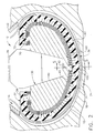
- the probe 10 is sized and shaped for inspecting a preselected surface 12 (e.g., a dovetail slot bottom of a gas turbine engine disk) at least partially defining an opening, generally designated by 14, in a component 16 (partially shown in Fig. 1).
- the probe 10 is mounted on a conventional fixture 18 positioned adjacent the component 16 to be inspected.
- the probe 10 generally comprises a base 20 which is mounted on the fixture 18, a support 22 extending downward from the base, a head (generally designated by 24) and an actuation rod 26 extending downward through the support.
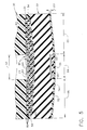
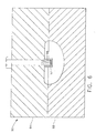
- the rod 26 is operatively connected to a conventional actuator 28 for moving the head 24 between a retracted position as shown in Fig. 2 and an expanded position as shown in Fig. 3.
- the head 24 comprises a core (generally designated by 30), a compliant covering (generally designated by 32), a layered element (generally designated by 34) positioned between the core and the covering, and an eddy current array (generally designated by 36).
- the eddy current array 36 is connected to a conventional eddy current instrument 38 for providing an output related to flaw size in the surface 12 of the component 16.
- the core 30 has an exterior surface 40 sized and shaped for receipt within the opening 14 of the component 16.
- the core 30 has a centrally located slot 42 which intersects two lateral slots 44 which each intersect two longitudinal slots 46.
- a wedge-shaped opening 48 is provided above the central slot 42 for receiving the actuation rod 26.
- the slots 42, 44, 46 give a central portion 50 of the core 30 flexibility so the core can be moved between a retracted position (illustrated in Fig. 2) for inserting the probe 10 into and removing the probe from the opening 14 in the component 16 and an expanded position (illustrated in Fig.
- the probe is sized and shaped for at least partially filling the opening and contacting the preselected surface 12 of the component for inspecting the surface.
- the central portion 50 of the core 30 may have other lengths without departing from the scope of the present invention, the central portion of one embodiment has a length generally equal to the width of the eddy current array 36 as shown in Fig. 5.
- the core 30 may be made of other materials without departing from the scope of the present invention, the core of one embodiment is molded from semi-rigid polyurethane, such as Easyflo 60 available from Polytek Development Corporation of Easton Pennsylvania.
- the core 30 may have other hardnesses without departing from the scope of the present invention
- the core of one embodiment has a Type D durometer hardness of between about 60 and about 71, and more particularly a Type D durometer hardness of about 65.
- the core 30 may include threaded inserts 52 for attaching the core to the support 22.
- end margins 54 of the core 30 protrude outward from the exterior surface 40 of the core and are attached to the covering 32 to prevent the covering from becoming detached from and sliding over the core 30 due to shearing forces as the probe 10 is inserted in the opening 14 and/or drawn over the surface 12 selected for inspection.
- the covering 32 is positioned over the exterior surface 40 of the core 30 such that an inner face 60 of the covering faces the core.
- the covering 32 also has an outer face 62 opposite the inner face 60.
- the outer face 62 has a central portion 64 and opposite end portions 66 extending longitudinally outward from the central portion.
- a groove 68 is provided in the central portion 64 of the outer face 62 for receiving the eddy current array 36.
- the inner face 60 of the covering 32 includes longitudinal ribs 70 separated by longitudinal slots 72.
- the covering 32 of one embodiment is molded from polyurethane.
- the eddy current array 36 is positioned over the central portion 64 and within the groove 68 in the outer face 62 of the covering 32.
- the array 36 is adhesively bonded to the bottom of the groove 68 in the covering 32.
- the array 36 which is conventional, generates and detects magnetic fields in the component 16 to inspect the preselected surface 12 of the component.
- the eddy current array 36 has an outer surface shaped substantially identically to the preselected surface 12 of the component 16 when the core 30 is in the expanded position for contacting the probe 10 with the preselected surface of the component.
- a sacrificial sheet of protective material 74 having a low coefficient of friction (e.g, a polytetrafluoroethylene sheet) is adhesively bonded to the outer surface of the array 36 and the outer face 62 of the covering 32 to permit the probe 10 to easily slide across the preselected surface 12 of the component 16 as it is inserted in the opening 14 and removed from the opening.
- the sheet 74 may be made of other materials without departing from the scope of the present invention, the sheet of one embodiment is Teflon7 polytetrafluoroethylene tape having a nominal thickness of about 0.0045 inches.
- Teflon7 is a federally registered trademark of E.I. du Pont de Nemours and Company of Wilmington, Delaware.
- the element 34 is positioned between the exterior surface 40 of the core 30 and the inner face 60 of the covering 32.
- the element 34 has a laminated construction formed by a plurality of layers of sheet material.
- Two of the layers, generally designated by 80, have a coefficient of friction selected to permit the inner face 60 of the covering 32 to move tangentially with respect to the exterior surface 40 of the core 30 as the actuation rod 26 moves the core from the retracted position to the expanded position.
- these two layers 80 are slick thereby permitting the covering 32 to slide with respect to the core 30 so the covering does not distort from its intended shape as the core expands into the opening 14 of the component 16.
- the layers of one embodiment are Teflon7 polytetrafluoroethylene tape having a nominal thickness of about 0.0045 inches.
- Each layer of tape comprises a flexible sheet of polytetrafluoroethylene 82 and an adhesive layer 84.
- One adhesive layer 84 bonds the respective sheet 82 to the exterior surface 40 of the core 30, and the other adhesive layer bonds the respective sheet to the inner face 60 of the covering 32.
- the polytetrafluoroethylene sheets 82 face one another so the sheets are free to move tangentially with respect each other.
- the polytetrafluoroethylene tape layers have a low coefficient of friction allowing the layers to slip tangentially with respect to each other. Further, these layers do not extend the full length of the probe 10 so the cover 32 is longitudinally retained on the core 30. In one embodiment, these layers only extend over the length of the slotted region of the core 30.
- the element 34 also includes several probe shaping layers of compressibly resilient material 86. As illustrated in Fig. 5, more layers of material 86 underlie the central portion 64 of the cover 32 than underlie the opposite end portions 66 of the covering. As a result, the central portion of the element 34 is thicker than the end portions and the central portion of the outer face 60 of the covering 32 and the array 36 are raised above the end portions of the outer face of the covering. This ensures a tight fit between the array 36 and the surface 12 being inspected but tapers the exterior surface 40 of the cover for easing insertion of the central portion of the covering and the array into the opening.
- the layers of compressibly resilient material 86 may be made of other materials without departing from the scope of the present invention, the layers of one embodiment are made of Kapton7 tape having a nominal thickness of about 0.003 inches. Kapton is a federally registered trademark of E.I. du Pont de Nemours and Company. The adhesive layer of the Kapton7 tape provides the layered element 34 with its compressible resilience.
- the core 30 Prior to assembling the probe 10 described above, the core 30 is cast.
- the probe 10 may be cast from other materials without departing from the scope of the present invention, in one embodiment the probe 10 is cast from an elastomer such as a polyurethane or a silicone rubber.
- an Easyflo 60 polyurethane epoxy is mixed by hand for between about 45 seconds and about one minute. The mixed epoxy is poured into a mold, generally designated by 90, formed by married mold halves 92, 94 as illustrated in Fig. 6 shaped for producing the core 30.
- a dry mold release agent is used on the mold 90.
- a MS-122DF PTFE Release Agent - Dry Lubricant available from Miller-Stephenson Chemical Company, Inc. of Morton Grove, Illinois, is sprayed in the mold 90.
- the threaded inserts 52 Prior to pouring the epoxy into the mold 90, the threaded inserts 52 are positioned on threaded posts 96 on the upper mold half 94 so the inserts join with the core 30 as the epoxy cures.
- the epoxy is allowed to cure before the halves 92, 94 are separated. Although the epoxy may be allowed to cure for other periods of time without departing from the scope of the present invention, in one embodiment the epoxy is cured for between about fifteen minutes and about thirty minutes before the core 30 is removed. It is envisioned that it may be desirable to allow the epoxy to cure for about twenty minutes before separating the halves 92, 94 of the mold 90. Although the mold 90 may be maintained at other temperatures without departing from the scope of the present invention, in one embodiment the halves 92, 94 are maintained at about 70 degrees Fahrenheit while the mold halves are married and the epoxy is cured. After the epoxy is cured, the mold 90 is opened and the core 30 is removed from the mold 90.
- the slots 42, 44, 46 are machined in the core. Although other methods of forming the slots 42, 44, 46 may be used without departing from the scope of the present invention, in one embodiment the slots are machined using conventional machining techniques. Alternatively, it is envisioned that the slots 42, 44, 46 may be cast into the core. Although other methods of forming the wedge-shaped opening 48 may be used without departing from the scope of the present invention, in one embodiment the opening is cast in the core. Alternatively, it is envisioned that the opening 48 may be machined using conventional machining techniques.
- the first layer 80 is bonded to the cast core 30, and cut along lines corresponding to the slots 42, 44, 46 in the core 30.
- Three probe shaping layers 86 are applied to each end of the core 30 adjacent the first layer 80.
- the second layer 80 is applied face-to-face over the first layer and held in place while the fourth probe shaping layer 86 is applied.
- the remaining layers 86 are applied to achieve the desired profile of the probe 10 as shown in Fig. 5.
- the layers 86 could be eliminated and/or replaced by a separately cast or machined element attached to the layers 80 by an adhesive or other conventional means.
- the ribbed covering 32 is positioned over and bonded to the layers 86.
- the end margins 54 of the core 30 are cast in place by applying a limited amount of polyurethane material over the ends of the layers 86 and allowing it to cure. A limited amount of polyurethane material is used to fill the end margins 54 to prevent it from filling the slots 72 between the ribs 70 in the covering 30 in the area over the layers 80.
- the array 36 is bonded in the slot 42 of the covering using transfer tape 100, and the sheet of material 74 is applied to the outer face 62 of the covering 32.
- the probe 10 is constructed so that when the core 30 is in the retracted position, the outer surface of the sheet of protective material 32 is sized and shaped substantially identically to a nominal opening 14 for which the probe is made.
- the eddy current array 36 is maintained at a preselected distance 102 from the surface 12 of the component 16.
- the probe 10 may be used in a conventional manner.
- the probe 10 is positioned in the opening of the component adjacent the surface to be inspected.
- the core 30 of the probe 10 is expanded by moving the actuation rod 26 to the position shown in Fig. 3 to at least partially fill the opening with the probe.
- the probe 10 contacts the preselected surface of the component so the outer surface of the array 36 remains at a preselected distance from the surface of the component.
- the array 36 is in this position, it is energized to generate and detect magnetic fields in the component to inspect the preselected surface of the component in a conventional manner such as by drawing the probe through the slot being inspected.
- the core 30 may be moved to a retracted position as shown in Fig. 4 for removing the probe 10 from the opening in the component.
Abstract
Description
- The present invention relates generally to eddy current inspection probes for inspecting a surface of a manufactured component, and more particularly to a probe having an improved fit with the surface of the component.
- Eddy current inspection is commonly used to detect flaws in surfaces of manufactured components such as gas turbine engine components. During this type of inspection, electromagnetic induction is used to induce eddy currents in the component being inspected. An array of coils inside an eddy current probe generates alternating magnetic fields which induce the eddy currents in the component when the probe is moved near the component. When flaws are present in the component, the flow of eddy currents is altered. The altered eddy currents produce changes in a secondary magnetic field which are detected by the array of coils inside the eddy current probe. The array generates an electrical signal in response to the altered secondary magnetic field. The amplitude of the electrical signal is generally proportionate to the size of the flaw. Thus, approximate sizes and general locations of flaws may be determined using eddy current probes.
- The array must be kept at a constant distance from the surface of the component being inspected to ensure the amplitude of the electrical signal is proportionate to flaw size. One way of ensuring a constant distance is by sizing and shaping the probe substantially identically to the feature being inspected. For instance, if the surface of an opening in a gas turbine engine disk such as a dovetail slot bottom is being inspected, a probe sized and shaped substantially identically to the opening is used.
- Frequently, the probe is made to collapse so it can fit into the opening. These collapsible probes generally have an expandable core inside a flexible covering which holds the array. In the past, the covering was bonded to the core. As a result, the covering stretched and distorted as it expanded. Changes in the probe shape prevented the array from being positioned at a uniform distance from the surface being inspected. Further, due to variations in size and shape of the actual features being inspected, gaps sometimes occurred between the probe and the surface which also prevented the array from being positioned at a uniform distance from the surface being inspected.
- Among the several features of the present invention may be noted the provision of an eddy current inspection probe for inspecting a preselected surface at least partially defining an opening in a component. The eddy current inspection probe comprises a cast core having an exterior surface sized and shaped for receipt within the opening of the component. The core is resiliently deformable between a retracted position for inserting the probe into and removing the probe from the opening in the component and an expanded position in which the probe is sized and shaped for at least partially filling the opening and contacting the preselected surface of the component for inspecting the surface. Further, the probe includes an eddy current array positioned over the exterior surface of the core for generating and detecting magnetic fields in the component to inspect the preselected surface of the component. The eddy current array has an outer surface shaped substantially identically to the preselected surface of the component when the core is in the expanded position for maintaining the outer surface of the array a preselected distance from the surface of the component.
- In another aspect, the present invention includes a method of making a core for an eddy current inspection probe. A polyurethane epoxy is mixed and poured into a mold shaped for producing the core. The mold is opened after a period of time sufficient for the epoxy to cure, and the core is removed from the mold.
- In yet another aspect of the present invention a core having an exterior surface sized and shaped for receipt within the opening of the component is molded, and an element is positioned over the exterior surface of the core. A compliant covering is positioned over an outer face of the element. An eddy current array is positioned over the covering for generating and detecting magnetic fields in the component to inspect the preselected surface of the component.
- An embodiment of the invention will now be described, by way of example, with reference to the accompanying drawings, in which:
- Fig. 1 is a vertical cross section of an eddy current inspection probe of the present invention shown in an opening of a component;
- Fig. 2 is a detail of the probe and component showing the probe in a contracted position;
- Fig. 3 is a detail similar to Fig. 2 showing the probe in an expanded position;
- Fig. 4 is a perspective of a core of the probe;
- Fig. 5 is a cross section of the probe taken in the plane of line 5-5 of Fig. 2; and
- Fig. 6 is a cross section of a mold for casting the core of the probe taken in the plane of line 6-6 of Fig. 4.
-
- Corresponding reference characters indicate corresponding parts throughout the several views of the drawings.
- Referring now to the drawings and in particular to Fig. 1, an eddy current inspection probe of the present invention is designated in its entirety by the
reference number 10. Theprobe 10 is sized and shaped for inspecting a preselected surface 12 (e.g., a dovetail slot bottom of a gas turbine engine disk) at least partially defining an opening, generally designated by 14, in a component 16 (partially shown in Fig. 1). Theprobe 10 is mounted on aconventional fixture 18 positioned adjacent thecomponent 16 to be inspected. - The
probe 10 generally comprises abase 20 which is mounted on thefixture 18, asupport 22 extending downward from the base, a head (generally designated by 24) and anactuation rod 26 extending downward through the support. Therod 26 is operatively connected to aconventional actuator 28 for moving thehead 24 between a retracted position as shown in Fig. 2 and an expanded position as shown in Fig. 3. As illustrated in Fig. 2, thehead 24 comprises a core (generally designated by 30), a compliant covering (generally designated by 32), a layered element (generally designated by 34) positioned between the core and the covering, and an eddy current array (generally designated by 36). As shown in Fig. 1, the eddycurrent array 36 is connected to a conventional eddycurrent instrument 38 for providing an output related to flaw size in thesurface 12 of thecomponent 16. - As shown in Fig. 2, the
core 30 has anexterior surface 40 sized and shaped for receipt within theopening 14 of thecomponent 16. As illustrated in Fig. 4, thecore 30 has a centrally locatedslot 42 which intersects twolateral slots 44 which each intersect twolongitudinal slots 46. In addition, a wedge-shaped opening 48 is provided above thecentral slot 42 for receiving theactuation rod 26. Theslots central portion 50 of thecore 30 flexibility so the core can be moved between a retracted position (illustrated in Fig. 2) for inserting theprobe 10 into and removing the probe from theopening 14 in thecomponent 16 and an expanded position (illustrated in Fig. 3) in which the probe is sized and shaped for at least partially filling the opening and contacting the preselectedsurface 12 of the component for inspecting the surface. Although thecentral portion 50 of thecore 30 may have other lengths without departing from the scope of the present invention, the central portion of one embodiment has a length generally equal to the width of the eddycurrent array 36 as shown in Fig. 5. Although thecore 30 may be made of other materials without departing from the scope of the present invention, the core of one embodiment is molded from semi-rigid polyurethane, such as Easyflo 60 available from Polytek Development Corporation of Easton Pennsylvania. Further, although thecore 30 may have other hardnesses without departing from the scope of the present invention, the core of one embodiment has a Type D durometer hardness of between about 60 and about 71, and more particularly a Type D durometer hardness of about 65. As further illustrated in Fig. 4, thecore 30 may include threadedinserts 52 for attaching the core to thesupport 22. As illustrated in Fig. 5,end margins 54 of thecore 30 protrude outward from theexterior surface 40 of the core and are attached to thecovering 32 to prevent the covering from becoming detached from and sliding over thecore 30 due to shearing forces as theprobe 10 is inserted in theopening 14 and/or drawn over thesurface 12 selected for inspection. - The
covering 32 is positioned over theexterior surface 40 of thecore 30 such that aninner face 60 of the covering faces the core. The covering 32 also has anouter face 62 opposite theinner face 60. Theouter face 62 has acentral portion 64 andopposite end portions 66 extending longitudinally outward from the central portion. As illustrated in Fig. 5, agroove 68 is provided in thecentral portion 64 of theouter face 62 for receiving the eddycurrent array 36. As illustrated in Fig. 2, theinner face 60 of thecovering 32 includeslongitudinal ribs 70 separated bylongitudinal slots 72. Although the covering may be made of other materials without departing from the scope of the present invention, the covering 32 of one embodiment is molded from polyurethane. - As illustrated in Fig. 5, the eddy
current array 36 is positioned over thecentral portion 64 and within thegroove 68 in theouter face 62 of thecovering 32. Thearray 36 is adhesively bonded to the bottom of thegroove 68 in the covering 32. Thearray 36, which is conventional, generates and detects magnetic fields in thecomponent 16 to inspect the preselectedsurface 12 of the component. The eddycurrent array 36 has an outer surface shaped substantially identically to the preselectedsurface 12 of thecomponent 16 when thecore 30 is in the expanded position for contacting theprobe 10 with the preselected surface of the component. A sacrificial sheet ofprotective material 74 having a low coefficient of friction (e.g, a polytetrafluoroethylene sheet) is adhesively bonded to the outer surface of thearray 36 and theouter face 62 of thecovering 32 to permit theprobe 10 to easily slide across the preselectedsurface 12 of thecomponent 16 as it is inserted in theopening 14 and removed from the opening. Although thesheet 74 may be made of other materials without departing from the scope of the present invention, the sheet of one embodiment is Teflon7 polytetrafluoroethylene tape having a nominal thickness of about 0.0045 inches. - Teflon7 is a federally registered trademark of E.I. du Pont de Nemours and Company of Wilmington, Delaware.
- As further illustrated in Fig. 5, the
element 34 is positioned between theexterior surface 40 of thecore 30 and theinner face 60 of thecovering 32. Theelement 34 has a laminated construction formed by a plurality of layers of sheet material. Two of the layers, generally designated by 80, have a coefficient of friction selected to permit theinner face 60 of the covering 32 to move tangentially with respect to theexterior surface 40 of the core 30 as theactuation rod 26 moves the core from the retracted position to the expanded position. In other words, these twolayers 80 are slick thereby permitting the covering 32 to slide with respect to the core 30 so the covering does not distort from its intended shape as the core expands into theopening 14 of thecomponent 16. This ensures intimate contact between theprobe 10 and the preselectedsurface 12 of thecomponent 16 being inspected. Although the twolayers 80 may be made of other materials without departing from the scope of the present invention, the layers of one embodiment are Teflon7 polytetrafluoroethylene tape having a nominal thickness of about 0.0045 inches. Each layer of tape comprises a flexible sheet ofpolytetrafluoroethylene 82 and anadhesive layer 84. Oneadhesive layer 84 bonds therespective sheet 82 to theexterior surface 40 of the core 30, and the other adhesive layer bonds the respective sheet to theinner face 60 of thecovering 32. Thus, thepolytetrafluoroethylene sheets 82 face one another so the sheets are free to move tangentially with respect each other. As will be appreciated by those skilled in the art, the polytetrafluoroethylene tape layers have a low coefficient of friction allowing the layers to slip tangentially with respect to each other. Further, these layers do not extend the full length of theprobe 10 so thecover 32 is longitudinally retained on thecore 30. In one embodiment, these layers only extend over the length of the slotted region of thecore 30. - The
element 34 also includes several probe shaping layers of compressiblyresilient material 86. As illustrated in Fig. 5, more layers ofmaterial 86 underlie thecentral portion 64 of thecover 32 than underlie theopposite end portions 66 of the covering. As a result, the central portion of theelement 34 is thicker than the end portions and the central portion of theouter face 60 of the covering 32 and thearray 36 are raised above the end portions of the outer face of the covering. This ensures a tight fit between thearray 36 and thesurface 12 being inspected but tapers theexterior surface 40 of the cover for easing insertion of the central portion of the covering and the array into the opening. Although the layers of compressiblyresilient material 86 may be made of other materials without departing from the scope of the present invention, the layers of one embodiment are made of Kapton7 tape having a nominal thickness of about 0.003 inches. Kapton is a federally registered trademark of E.I. du Pont de Nemours and Company. The adhesive layer of the Kapton7 tape provides thelayered element 34 with its compressible resilience. - Prior to assembling the
probe 10 described above, thecore 30 is cast. Although theprobe 10 may be cast from other materials without departing from the scope of the present invention, in one embodiment theprobe 10 is cast from an elastomer such as a polyurethane or a silicone rubber. In one embodiment, anEasyflo 60 polyurethane epoxy is mixed by hand for between about 45 seconds and about one minute. The mixed epoxy is poured into a mold, generally designated by 90, formed bymarried mold halves core 30. Although it is envisioned that other mold releases may be applied to the mold halves 92, 94 before the epoxy is poured into them (or alternatively, that no mold releases are used), in one embodiment a dry mold release agent is used on themold 90. Although other dry mold release agents may be used without departing from the scope of the present invention, in one embodiment a MS-122DF PTFE Release Agent - Dry Lubricant available from Miller-Stephenson Chemical Company, Inc. of Morton Grove, Illinois, is sprayed in themold 90. Prior to pouring the epoxy into themold 90, the threaded inserts 52 are positioned on threadedposts 96 on theupper mold half 94 so the inserts join with the core 30 as the epoxy cures. - The epoxy is allowed to cure before the
halves halves mold 90. Although themold 90 may be maintained at other temperatures without departing from the scope of the present invention, in one embodiment thehalves mold 90 is opened and thecore 30 is removed from themold 90. Once thecore 30 is removed from themold 90, theslots slots slots opening 48 may be used without departing from the scope of the present invention, in one embodiment the opening is cast in the core. Alternatively, it is envisioned that theopening 48 may be machined using conventional machining techniques. - To assemble the
probe 10, thefirst layer 80 is bonded to thecast core 30, and cut along lines corresponding to theslots core 30. Three probe shaping layers 86 are applied to each end of the core 30 adjacent thefirst layer 80. Thesecond layer 80 is applied face-to-face over the first layer and held in place while the fourthprobe shaping layer 86 is applied. The remaining layers 86 are applied to achieve the desired profile of theprobe 10 as shown in Fig. 5. Alternatively, it is envisioned that thelayers 86 could be eliminated and/or replaced by a separately cast or machined element attached to thelayers 80 by an adhesive or other conventional means. Theribbed covering 32 is positioned over and bonded to thelayers 86. Theend margins 54 of the core 30 are cast in place by applying a limited amount of polyurethane material over the ends of thelayers 86 and allowing it to cure. A limited amount of polyurethane material is used to fill theend margins 54 to prevent it from filling theslots 72 between theribs 70 in the covering 30 in the area over thelayers 80. Thearray 36 is bonded in theslot 42 of the covering usingtransfer tape 100, and the sheet ofmaterial 74 is applied to theouter face 62 of thecovering 32. Preferably, theprobe 10 is constructed so that when thecore 30 is in the retracted position, the outer surface of the sheet ofprotective material 32 is sized and shaped substantially identically to anominal opening 14 for which the probe is made. Thus, when thecore 30 is moved to the expanded position, theeddy current array 36 is maintained at apreselected distance 102 from thesurface 12 of thecomponent 16. - Once assembled, the
probe 10 may be used in a conventional manner. First, theprobe 10 is positioned in the opening of the component adjacent the surface to be inspected. After being so positioned, thecore 30 of theprobe 10 is expanded by moving theactuation rod 26 to the position shown in Fig. 3 to at least partially fill the opening with the probe. As the core expands, theprobe 10 contacts the preselected surface of the component so the outer surface of thearray 36 remains at a preselected distance from the surface of the component. When thearray 36 is in this position, it is energized to generate and detect magnetic fields in the component to inspect the preselected surface of the component in a conventional manner such as by drawing the probe through the slot being inspected. After the eddy current inspection is completed, thecore 30 may be moved to a retracted position as shown in Fig. 4 for removing theprobe 10 from the opening in the component. - When introducing elements of the present invention or the preferred embodiment(s) thereof, the articles "a", "an", "the" and "said" are intended to mean that there are one or more of the elements. The terms "comprising", "including" and "having" are intended to be inclusive and mean that there may be additional elements other than the listed elements.
Claims (7)
- An eddy current inspection probe (10) for inspecting a preselected surface (12) at least partially defining an opening (14) in a component (16), said eddy current inspection probe (10) comprising:a cast core (30) having an exterior surface (40) sized and shaped for receipt within the opening (14) of the component (16), the core (30) being resiliently deformable between a retracted position for inserting the probe (10) into and removing the probe (10) from the opening (14) in the component (16) and an expanded position in which the probe (10) is sized and shaped for at least partially filling the opening (14) and contacting the preselected surface (12) of the component (16) for inspecting the surface (12); andan eddy current array (36) positioned over the exterior surface (40) of the core (30) for generating and detecting magnetic fields in the component (16) to inspect the preselected surface (12) of the component (16), the eddy current array (36) having an outer surface shaped substantially identically to the preselected surface (12) of the component (16) when the core (30) is in the expanded position for maintaining the outer surface of the array (36) a preselected distance from the surface (12) of the component (16).
- A probe (10) as set forth in claim 1 further comprising a compliant covering (32) positioned between the exterior surface (40) of the core (30) and the eddy current array (36) having an inner face (60) facing the core (30) and an outer face (62) opposite the inner face (60).
- A probe (10) as set forth in claim 2 further comprising an element (34) positioned between the exterior surface (40) of the core (30) and the inner face (60) of the covering (32) having a coefficient of friction selected to permit the inner face (60) of the covering (32) to move tangentially with respect to the exterior surface (40) of the core (30) as the core (30) is moved from the retracted position to the expanded position to ensure intimate contact between the probe (10) and the preselected surface (12) of the component (16) being inspected.
- A probe (10) as set forth in claim 1 wherein the cast core (30) has a Type D durometer hardness of between about 60 and about 71.
- A probe (10) as set forth in claim 4 wherein the cast core (30) has a Type D durometer hardness of about 65.
- A probe (10) as set forth in claim 1 wherein the cast core (30) is made from an elastomer.
- A probe (10) as set forth in claim 1 wherein the elastomer is a polyurethane.
Applications Claiming Priority (2)
| Application Number | Priority Date | Filing Date | Title |
|---|---|---|---|
| US09/817,873 US6469503B2 (en) | 2001-03-26 | 2001-03-26 | Eddy current inspection probe and method of use |
| US817873 | 2001-03-26 |
Publications (2)
| Publication Number | Publication Date |
|---|---|
| EP1245953A1 true EP1245953A1 (en) | 2002-10-02 |
| EP1245953B1 EP1245953B1 (en) | 2009-08-26 |
Family
ID=25224067
Family Applications (1)
| Application Number | Title | Priority Date | Filing Date |
|---|---|---|---|
| EP02250502A Expired - Lifetime EP1245953B1 (en) | 2001-03-26 | 2002-01-25 | Eddy current inspection probe |
Country Status (3)
| Country | Link |
|---|---|
| US (1) | US6469503B2 (en) |
| EP (1) | EP1245953B1 (en) |
| DE (1) | DE60233454D1 (en) |
Cited By (3)
| Publication number | Priority date | Publication date | Assignee | Title |
|---|---|---|---|---|
| EP1416122A2 (en) * | 2002-10-31 | 2004-05-06 | General Electric Company | Apparatus and method for inspecting dovetail slot width for gas turbine engine rotor disk |
| FR2931242A1 (en) * | 2008-05-14 | 2009-11-20 | Snecma Sa | PROBE INTENDED FOR CURRENT FOUCAULT CONTROL OF THE SURFACE OF A CIRCONFERENTIAL ALVEOLE OF A TURBOREACTOR DISC |
| WO2015004364A1 (en) * | 2013-07-10 | 2015-01-15 | Snecma | Device for inspecting the surface of an electrically conductive part |
Families Citing this family (10)
| Publication number | Priority date | Publication date | Assignee | Title |
|---|---|---|---|---|
| US6696830B2 (en) * | 2002-02-05 | 2004-02-24 | General Electric Company | Method and inspection standard for eddy current inspection |
| US6812697B2 (en) * | 2002-09-24 | 2004-11-02 | General Electric Company | Molded eddy current array probe |
| US7126329B2 (en) * | 2004-01-21 | 2006-10-24 | General Electric Company | Methods for preparing and testing a thermal-spray coated substrate |
| US7026811B2 (en) * | 2004-03-19 | 2006-04-11 | General Electric Company | Methods and apparatus for eddy current inspection of metallic posts |
| US7689030B2 (en) * | 2005-12-21 | 2010-03-30 | General Electric Company | Methods and apparatus for testing a component |
| CA2711129A1 (en) * | 2007-12-28 | 2009-07-09 | General Electric Company | Process and apparatus for testing a component using an omni-directional eddy current probe |
| GB2468098B (en) * | 2007-12-31 | 2012-03-07 | Gen Electric | Method for compensation of responses from eddy current probes |
| WO2012154729A1 (en) * | 2011-05-09 | 2012-11-15 | President And Fellows Of Harvard College | A microfluidic module and uses thereof |
| US9646599B2 (en) * | 2013-10-24 | 2017-05-09 | Spirit Aerosystems, Inc. | Remoldable contour sensor holder |
| CN104007172B (en) * | 2014-06-18 | 2017-02-01 | 武汉理工大学 | Engine cylinder lossless detection device |
Citations (8)
| Publication number | Priority date | Publication date | Assignee | Title |
|---|---|---|---|---|
| EP0095845A1 (en) * | 1982-05-28 | 1983-12-07 | Shur-Lok Corporation | Nondestructive testing apparatus utilizing eddy currents having an improved probe for use in holes |
| US4629984A (en) * | 1985-02-26 | 1986-12-16 | Scalese Joseph J | Ferromagnetic eddy current probe apparatus |
| US4668912A (en) * | 1985-02-05 | 1987-05-26 | Westinghouse Electric Corp. | Eddy current inspection probe and method for assembling same |
| EP0348739A1 (en) * | 1988-06-29 | 1990-01-03 | Siemens Aktiengesellschaft | Probe for testing tubes, particularly U-tubes of a heat exchanger |
| US5204622A (en) * | 1990-11-28 | 1993-04-20 | Westinghouse Electric Corp. | Improved probe for inspecting tubes having mechanism for maintaining alignment of probe axis of rotation |
| EP0577244A2 (en) * | 1992-04-03 | 1994-01-05 | General Electric Company | A device for inspecting a component |
| US5442286A (en) * | 1993-09-22 | 1995-08-15 | General Electric Company | Eddy current array inspection device |
| EP1202053A1 (en) * | 2000-10-27 | 2002-05-02 | General Electric Company | Contoured surface eddy current inspection system |
Family Cites Families (2)
| Publication number | Priority date | Publication date | Assignee | Title |
|---|---|---|---|---|
| US5903147A (en) | 1997-03-18 | 1999-05-11 | General Electric Company | Eddy current array inspection device for shaped holes |
| US6339326B1 (en) * | 2000-03-15 | 2002-01-15 | General Electric Company | Eddy current inspection probe |
-
2001
- 2001-03-26 US US09/817,873 patent/US6469503B2/en not_active Expired - Fee Related
-
2002
- 2002-01-25 EP EP02250502A patent/EP1245953B1/en not_active Expired - Lifetime
- 2002-01-25 DE DE60233454T patent/DE60233454D1/en not_active Expired - Lifetime
Patent Citations (8)
| Publication number | Priority date | Publication date | Assignee | Title |
|---|---|---|---|---|
| EP0095845A1 (en) * | 1982-05-28 | 1983-12-07 | Shur-Lok Corporation | Nondestructive testing apparatus utilizing eddy currents having an improved probe for use in holes |
| US4668912A (en) * | 1985-02-05 | 1987-05-26 | Westinghouse Electric Corp. | Eddy current inspection probe and method for assembling same |
| US4629984A (en) * | 1985-02-26 | 1986-12-16 | Scalese Joseph J | Ferromagnetic eddy current probe apparatus |
| EP0348739A1 (en) * | 1988-06-29 | 1990-01-03 | Siemens Aktiengesellschaft | Probe for testing tubes, particularly U-tubes of a heat exchanger |
| US5204622A (en) * | 1990-11-28 | 1993-04-20 | Westinghouse Electric Corp. | Improved probe for inspecting tubes having mechanism for maintaining alignment of probe axis of rotation |
| EP0577244A2 (en) * | 1992-04-03 | 1994-01-05 | General Electric Company | A device for inspecting a component |
| US5442286A (en) * | 1993-09-22 | 1995-08-15 | General Electric Company | Eddy current array inspection device |
| EP1202053A1 (en) * | 2000-10-27 | 2002-05-02 | General Electric Company | Contoured surface eddy current inspection system |
Cited By (10)
| Publication number | Priority date | Publication date | Assignee | Title |
|---|---|---|---|---|
| EP1416122A2 (en) * | 2002-10-31 | 2004-05-06 | General Electric Company | Apparatus and method for inspecting dovetail slot width for gas turbine engine rotor disk |
| EP1416122A3 (en) * | 2002-10-31 | 2006-08-09 | General Electric Company | Apparatus and method for inspecting dovetail slot width for gas turbine engine rotor disk |
| FR2931242A1 (en) * | 2008-05-14 | 2009-11-20 | Snecma Sa | PROBE INTENDED FOR CURRENT FOUCAULT CONTROL OF THE SURFACE OF A CIRCONFERENTIAL ALVEOLE OF A TURBOREACTOR DISC |
| WO2009147351A2 (en) * | 2008-05-14 | 2009-12-10 | Snecma | Probe for controlling the surface of a circumferential recess of a turbojet engine disc using foucault currents |
| WO2009147351A3 (en) * | 2008-05-14 | 2010-03-11 | Snecma | Probe for controlling the surface of a circumferential recess of a turbojet engine disc using foucault currents |
| CN102027363B (en) * | 2008-05-14 | 2012-09-26 | 斯奈克玛 | Probe for controlling the surface of a circumferential recess of a turbojet engine disc using foucault currents |
| US8866471B2 (en) | 2008-05-14 | 2014-10-21 | Snecma | Probe for inspecting the surface of a circumferential slot in a turbojet disk by means of eddy currents |
| WO2015004364A1 (en) * | 2013-07-10 | 2015-01-15 | Snecma | Device for inspecting the surface of an electrically conductive part |
| FR3008490A1 (en) * | 2013-07-10 | 2015-01-16 | Snecma | DEVICE FOR INSPECTING A SURFACE OF AN ELECTRICALLY CONDUCTIVE PIECE |
| US10101300B2 (en) | 2013-07-10 | 2018-10-16 | Safran Aircraft Engines | Device for inspecting a surface of an electrically conductive part |
Also Published As
| Publication number | Publication date |
|---|---|
| US6469503B2 (en) | 2002-10-22 |
| DE60233454D1 (en) | 2009-10-08 |
| US20020135363A1 (en) | 2002-09-26 |
| EP1245953B1 (en) | 2009-08-26 |
Similar Documents
| Publication | Publication Date | Title |
|---|---|---|
| EP1245953B1 (en) | Eddy current inspection probe | |
| JP4464096B2 (en) | Synthetic eddy current array probe | |
| US6339326B1 (en) | Eddy current inspection probe | |
| PL321252A1 (en) | Diagnostic testing medium with a multilayer test field and method of determining material analysed by means of such testing medium | |
| EP2541190A1 (en) | Method and apparatus for measuring spaces with limited access | |
| DE68919622D1 (en) | Particle analyzer and method for determining a core displacement measurement number. | |
| DE59812700D1 (en) | MR method and MR arrangement for determining the position of a microcoil | |
| BR102017018188B1 (en) | SYSTEM AND METHOD FOR ATTACHING ACOUSTIC EMISSION SENSORS TO A NON-METALLIC AND NON-MAGNETIC MATERIAL | |
| DE69727446D1 (en) | Non-magnetic toner for developing electrostatic images, manufacturing processes for non-magnetic toner particles, and their use in the imaging process | |
| EP0291081A1 (en) | Elastic roller for fixing and method of producing the same | |
| US5483839A (en) | Multi-pitot tube assembly | |
| CN111623741A (en) | Plug gauge and method for performing multiple simultaneous diameter measurements | |
| KR880000052A (en) | Fastener assembly | |
| US5185046A (en) | Method for non-destructive estimation of waveguide directional coupler dimensions | |
| CN112673253B (en) | Manufacturing and detecting method of fiber plastic composite material reference body | |
| Parks et al. | Photoelastic analysis of plates subjected to restrained shrinkage | |
| US3791207A (en) | Wind tunnel model and method | |
| US10192681B2 (en) | Method of manufacturing a cryogenic coil assembly | |
| DE69930436D1 (en) | A mass transfer apparatus comprising a fiber reinforced composite body cladding having an inner surface of fluoropolymer and method of making the same | |
| KR101899647B1 (en) | Test-piece auxiliary apparatus for fatigue test | |
| WO2001036147A1 (en) | Multi-purpose universal weld test system | |
| EP1281956A1 (en) | Compliant laminar eddy current sensitivity standard | |
| US20090160437A1 (en) | Eddy Current Probe And Method Of Manufacture Thereof | |
| Williford | Estimation of fracture energy from fracture surface roughness | |
| Alqaradawi | Structural damage diagnosis using stereolithography, experimental modal analysis and finite element analysis |
Legal Events
| Date | Code | Title | Description |
|---|---|---|---|
| PUAI | Public reference made under article 153(3) epc to a published international application that has entered the european phase |
Free format text: ORIGINAL CODE: 0009012 |
|
| AK | Designated contracting states |
Kind code of ref document: A1 Designated state(s): AT BE CH CY DE DK ES FI FR GB GR IE IT LI LU MC NL PT SE TR |
|
| AX | Request for extension of the european patent |
Free format text: AL;LT;LV;MK;RO;SI |
|
| 17P | Request for examination filed |
Effective date: 20030402 |
|
| AKX | Designation fees paid |
Designated state(s): DE FR GB |
|
| 17Q | First examination report despatched |
Effective date: 20050214 |
|
| APBN | Date of receipt of notice of appeal recorded |
Free format text: ORIGINAL CODE: EPIDOSNNOA2E |
|
| APBR | Date of receipt of statement of grounds of appeal recorded |
Free format text: ORIGINAL CODE: EPIDOSNNOA3E |
|
| APBV | Interlocutory revision of appeal recorded |
Free format text: ORIGINAL CODE: EPIDOSNIRAPE |
|
| GRAP | Despatch of communication of intention to grant a patent |
Free format text: ORIGINAL CODE: EPIDOSNIGR1 |
|
| GRAS | Grant fee paid |
Free format text: ORIGINAL CODE: EPIDOSNIGR3 |
|
| GRAA | (expected) grant |
Free format text: ORIGINAL CODE: 0009210 |
|
| AK | Designated contracting states |
Kind code of ref document: B1 Designated state(s): DE FR GB |
|
| REG | Reference to a national code |
Ref country code: GB Ref legal event code: FG4D |
|
| REF | Corresponds to: |
Ref document number: 60233454 Country of ref document: DE Date of ref document: 20091008 Kind code of ref document: P |
|
| PGFP | Annual fee paid to national office [announced via postgrant information from national office to epo] |
Ref country code: FR Payment date: 20100205 Year of fee payment: 9 |
|
| PGFP | Annual fee paid to national office [announced via postgrant information from national office to epo] |
Ref country code: GB Payment date: 20100125 Year of fee payment: 9 Ref country code: DE Payment date: 20100127 Year of fee payment: 9 |
|
| PLBE | No opposition filed within time limit |
Free format text: ORIGINAL CODE: 0009261 |
|
| STAA | Information on the status of an ep patent application or granted ep patent |
Free format text: STATUS: NO OPPOSITION FILED WITHIN TIME LIMIT |
|
| 26N | No opposition filed |
Effective date: 20100527 |
|
| GBPC | Gb: european patent ceased through non-payment of renewal fee |
Effective date: 20110125 |
|
| REG | Reference to a national code |
Ref country code: FR Ref legal event code: ST Effective date: 20110930 |
|
| PG25 | Lapsed in a contracting state [announced via postgrant information from national office to epo] |
Ref country code: FR Free format text: LAPSE BECAUSE OF NON-PAYMENT OF DUE FEES Effective date: 20110131 |
|
| PG25 | Lapsed in a contracting state [announced via postgrant information from national office to epo] |
Ref country code: GB Free format text: LAPSE BECAUSE OF NON-PAYMENT OF DUE FEES Effective date: 20110125 |
|
| REG | Reference to a national code |
Ref country code: DE Ref legal event code: R119 Ref document number: 60233454 Country of ref document: DE Effective date: 20110802 |
|
| PG25 | Lapsed in a contracting state [announced via postgrant information from national office to epo] |
Ref country code: DE Free format text: LAPSE BECAUSE OF NON-PAYMENT OF DUE FEES Effective date: 20110802 |