EP1247153B1 - Computer with pressure-sensitive means, method of computer having a pressure-sensitive means and vibration means, method of using the same and recording medium for the method - Google Patents
Computer with pressure-sensitive means, method of computer having a pressure-sensitive means and vibration means, method of using the same and recording medium for the method Download PDFInfo
- Publication number
- EP1247153B1 EP1247153B1 EP01900722A EP01900722A EP1247153B1 EP 1247153 B1 EP1247153 B1 EP 1247153B1 EP 01900722 A EP01900722 A EP 01900722A EP 01900722 A EP01900722 A EP 01900722A EP 1247153 B1 EP1247153 B1 EP 1247153B1
- Authority
- EP
- European Patent Office
- Prior art keywords
- controller
- pressure
- vibration
- control
- computer
- Prior art date
- Legal status (The legal status is an assumption and is not a legal conclusion. Google has not performed a legal analysis and makes no representation as to the accuracy of the status listed.)
- Expired - Lifetime
Links
Images


Classifications
-
- A63F13/10—
-
- A—HUMAN NECESSITIES
- A63—SPORTS; GAMES; AMUSEMENTS
- A63F—CARD, BOARD, OR ROULETTE GAMES; INDOOR GAMES USING SMALL MOVING PLAYING BODIES; VIDEO GAMES; GAMES NOT OTHERWISE PROVIDED FOR
- A63F13/00—Video games, i.e. games using an electronically generated display having two or more dimensions
- A63F13/25—Output arrangements for video game devices
- A63F13/28—Output arrangements for video game devices responding to control signals received from the game device for affecting ambient conditions, e.g. for vibrating players' seats, activating scent dispensers or affecting temperature or light
- A63F13/285—Generating tactile feedback signals via the game input device, e.g. force feedback
-
- A—HUMAN NECESSITIES
- A63—SPORTS; GAMES; AMUSEMENTS
- A63F—CARD, BOARD, OR ROULETTE GAMES; INDOOR GAMES USING SMALL MOVING PLAYING BODIES; VIDEO GAMES; GAMES NOT OTHERWISE PROVIDED FOR
- A63F13/00—Video games, i.e. games using an electronically generated display having two or more dimensions
- A63F13/20—Input arrangements for video game devices
- A63F13/21—Input arrangements for video game devices characterised by their sensors, purposes or types
- A63F13/218—Input arrangements for video game devices characterised by their sensors, purposes or types using pressure sensors, e.g. generating a signal proportional to the pressure applied by the player
-
- A—HUMAN NECESSITIES
- A63—SPORTS; GAMES; AMUSEMENTS
- A63F—CARD, BOARD, OR ROULETTE GAMES; INDOOR GAMES USING SMALL MOVING PLAYING BODIES; VIDEO GAMES; GAMES NOT OTHERWISE PROVIDED FOR
- A63F13/00—Video games, i.e. games using an electronically generated display having two or more dimensions
- A63F13/45—Controlling the progress of the video game
-
- G—PHYSICS
- G06—COMPUTING; CALCULATING OR COUNTING
- G06F—ELECTRIC DIGITAL DATA PROCESSING
- G06F3/00—Input arrangements for transferring data to be processed into a form capable of being handled by the computer; Output arrangements for transferring data from processing unit to output unit, e.g. interface arrangements
- G06F3/01—Input arrangements or combined input and output arrangements for interaction between user and computer
- G06F3/016—Input arrangements with force or tactile feedback as computer generated output to the user
-
- G—PHYSICS
- G06—COMPUTING; CALCULATING OR COUNTING
- G06F—ELECTRIC DIGITAL DATA PROCESSING
- G06F3/00—Input arrangements for transferring data to be processed into a form capable of being handled by the computer; Output arrangements for transferring data from processing unit to output unit, e.g. interface arrangements
- G06F3/01—Input arrangements or combined input and output arrangements for interaction between user and computer
- G06F3/03—Arrangements for converting the position or the displacement of a member into a coded form
- G06F3/033—Pointing devices displaced or positioned by the user, e.g. mice, trackballs, pens or joysticks; Accessories therefor
- G06F3/0338—Pointing devices displaced or positioned by the user, e.g. mice, trackballs, pens or joysticks; Accessories therefor with detection of limited linear or angular displacement of an operating part of the device from a neutral position, e.g. isotonic or isometric joysticks
-
- H—ELECTRICITY
- H01—ELECTRIC ELEMENTS
- H01H—ELECTRIC SWITCHES; RELAYS; SELECTORS; EMERGENCY PROTECTIVE DEVICES
- H01H13/00—Switches having rectilinearly-movable operating part or parts adapted for pushing or pulling in one direction only, e.g. push-button switch
- H01H13/70—Switches having rectilinearly-movable operating part or parts adapted for pushing or pulling in one direction only, e.g. push-button switch having a plurality of operating members associated with different sets of contacts, e.g. keyboard
- H01H13/78—Switches having rectilinearly-movable operating part or parts adapted for pushing or pulling in one direction only, e.g. push-button switch having a plurality of operating members associated with different sets of contacts, e.g. keyboard characterised by the contacts or the contact sites
- H01H13/785—Switches having rectilinearly-movable operating part or parts adapted for pushing or pulling in one direction only, e.g. push-button switch having a plurality of operating members associated with different sets of contacts, e.g. keyboard characterised by the contacts or the contact sites characterised by the material of the contacts, e.g. conductive polymers
-
- A—HUMAN NECESSITIES
- A63—SPORTS; GAMES; AMUSEMENTS
- A63F—CARD, BOARD, OR ROULETTE GAMES; INDOOR GAMES USING SMALL MOVING PLAYING BODIES; VIDEO GAMES; GAMES NOT OTHERWISE PROVIDED FOR
- A63F2300/00—Features of games using an electronically generated display having two or more dimensions, e.g. on a television screen, showing representations related to the game
- A63F2300/10—Features of games using an electronically generated display having two or more dimensions, e.g. on a television screen, showing representations related to the game characterized by input arrangements for converting player-generated signals into game device control signals
- A63F2300/1037—Features of games using an electronically generated display having two or more dimensions, e.g. on a television screen, showing representations related to the game characterized by input arrangements for converting player-generated signals into game device control signals being specially adapted for converting control signals received from the game device into a haptic signal, e.g. using force feedback
-
- A—HUMAN NECESSITIES
- A63—SPORTS; GAMES; AMUSEMENTS
- A63F—CARD, BOARD, OR ROULETTE GAMES; INDOOR GAMES USING SMALL MOVING PLAYING BODIES; VIDEO GAMES; GAMES NOT OTHERWISE PROVIDED FOR
- A63F2300/00—Features of games using an electronically generated display having two or more dimensions, e.g. on a television screen, showing representations related to the game
- A63F2300/10—Features of games using an electronically generated display having two or more dimensions, e.g. on a television screen, showing representations related to the game characterized by input arrangements for converting player-generated signals into game device control signals
- A63F2300/1056—Features of games using an electronically generated display having two or more dimensions, e.g. on a television screen, showing representations related to the game characterized by input arrangements for converting player-generated signals into game device control signals involving pressure sensitive buttons
-
- A—HUMAN NECESSITIES
- A63—SPORTS; GAMES; AMUSEMENTS
- A63F—CARD, BOARD, OR ROULETTE GAMES; INDOOR GAMES USING SMALL MOVING PLAYING BODIES; VIDEO GAMES; GAMES NOT OTHERWISE PROVIDED FOR
- A63F2300/00—Features of games using an electronically generated display having two or more dimensions, e.g. on a television screen, showing representations related to the game
- A63F2300/60—Methods for processing data by generating or executing the game program
- A63F2300/63—Methods for processing data by generating or executing the game program for controlling the execution of the game in time
- A63F2300/638—Methods for processing data by generating or executing the game program for controlling the execution of the game in time according to the timing of operation or a time limit
-
- G—PHYSICS
- G06—COMPUTING; CALCULATING OR COUNTING
- G06F—ELECTRIC DIGITAL DATA PROCESSING
- G06F2203/00—Indexing scheme relating to G06F3/00 - G06F3/048
- G06F2203/01—Indexing scheme relating to G06F3/01
- G06F2203/013—Force feedback applied to a game
-
- H—ELECTRICITY
- H01—ELECTRIC ELEMENTS
- H01H—ELECTRIC SWITCHES; RELAYS; SELECTORS; EMERGENCY PROTECTIVE DEVICES
- H01H3/00—Mechanisms for operating contacts
- H01H2003/008—Mechanisms for operating contacts with a haptic or a tactile feedback controlled by electrical means, e.g. a motor or magnetofriction
-
- H—ELECTRICITY
- H01—ELECTRIC ELEMENTS
- H01H—ELECTRIC SWITCHES; RELAYS; SELECTORS; EMERGENCY PROTECTIVE DEVICES
- H01H2201/00—Contacts
- H01H2201/022—Material
- H01H2201/032—Conductive polymer; Rubber
- H01H2201/036—Variable resistance
-
- H—ELECTRICITY
- H01—ELECTRIC ELEMENTS
- H01H—ELECTRIC SWITCHES; RELAYS; SELECTORS; EMERGENCY PROTECTIVE DEVICES
- H01H2221/00—Actuators
- H01H2221/008—Actuators other then push button
- H01H2221/012—Joy stick type
-
- H—ELECTRICITY
- H01—ELECTRIC ELEMENTS
- H01H—ELECTRIC SWITCHES; RELAYS; SELECTORS; EMERGENCY PROTECTIVE DEVICES
- H01H2231/00—Applications
- H01H2231/008—Video game
-
- H—ELECTRICITY
- H01—ELECTRIC ELEMENTS
- H01H—ELECTRIC SWITCHES; RELAYS; SELECTORS; EMERGENCY PROTECTIVE DEVICES
- H01H2239/00—Miscellaneous
- H01H2239/078—Variable resistance by variable contact area or point
Definitions
- the present invention relates to a computer system having a pressure-sensitive means and vibrating means, a method of using same and computer software for implementing this method.
- a known example of a computer under consideration is the entertainment system, such as a game machine which is a typical example.
- Controllers that have vibration motors have been proposed as the controllers currently used for video game machines.
- Such controllers equipped with vibration motors have various vibration motors built into handles held by the user in the left and right hands.
- Such a controller is used for the feedback of various events during the game in the form of rotation of the vibration motors. Thereby, the user can feel a heightened sense of reality with these vibrations.
- a pressure-sensitive type controller was disclosed in the publication of examined Japanese utility model application No. JP-B-H1-40545, wherein pressure-sensitive output is provided as an input to a VCO (variable control oscillator) and the output of the VCO is used for repeated fire in a game.
- VCO variable control oscillator
- US-5808540 describes a biofeedback device that causes vibrations in accordance with the pressure applied to a lever.
- US-5619180 describes a method of controlling a remote effect, e.g. the application of a forcer, in which feedback in the form of vibration is provided to the operator, the amplitude of the vibrations being based on the remote force applied.
- US-6225975 discloses a controller for a gaming machine; the controller has a vibrator that is capable of vibrating and thereby causing the controller to vibrate.
- vibration depending on the pressure-sense value output at that time is output from a different controller.
- Fig. 1 is a schematic diagram showing an example of connecting an entertainment system 500 to a TV monitor 408 to enable a user to enjoy game software. More specific examples of the entertainment system are shown in Fig. 4.
- a controller 200 which has buttons connected to pressure-sensitive devices and a vibration generator consisting of a motor and a rotating member which is attached to the shaft of the motor such that it is asymmetric to the center of the shaft is connected to the entertainment system 500 used for playing games or enjoying DVD video or other types of video images, and the video output terminals are connected to the television monitor 408.
- the analog output from the pressure-sensitive devices is converted by an A/D converter to digital values in the range 0-255 and provided to the entertainment system 500.
- the aforementioned motor is driven and the aforementioned rotating member rotates, so that the vibration due to this rotation is transmitted to the player through the case of the controller.
- the controller 200 equipped with a pressure-sensitive switch and the vibration generator will be described in detail below.
- a head-to-head timing game which uses vibration generation will be now described.
- the game is played as follows. With two controllers 200 connected to the entertainment system 500, when one of the two players pushes a pressure-serisitive switch, vibration is generated on the other controller 200. If desired, when one of the two players pushes a pressure-sensitive switch, vibration may be generated on both controllers 200 (one's own and the other player's).
- Fig. 2 shows a pressure-sensed value-drive signal conversion table for selecting a drive signal corresponding to each of the pressure-sensed values "0"-"255". Using this table, each pressure-sensed value is converted to a drive signal.
- the drive signals P1-P255 corresponding to each of the pressure-sense values are supplied from the entertainment system 500 to the controller 200, and after conversion to analog signals by the A/D converter of the controller 200, they are given as drive signals for the motor of the vibration generator. It is to be noted that this conversion table is an example, and other tables may also be used.
- the present invention can offer the following alternative example.
- the pressure-sense value as pushed by the user is used as is.
- the maximum value of the user pressure-sensed value can be corrected to a maximum game pressure-sense value set in the program, and the intermediate values can be corrected proportionally. This type of correction is performed by preparing a correction table.
- the user pressure-sensed value can be corrected based upon a known function and used as the game pressure-sensed value. This type of correction is performed by creating a correction table that is stored in an appropriate storage unit prepared in advance.
- the maximum value of the user pressure-sensed value rate of change may be corrected to the maximum game pressure-sensed value rate of change set in the program, and intermediate values can be proportionally corrected and used.
- This type of correction is performed by creating a correction table.
- FIG. 3 shows the process of a game including a program for generating vibration depending on pressure-sensed values.
- the program for generating vibration depending on pressure-sensed values may be supplied either recorded alone on an optical disc or other recording medium, or recorded on the recording medium together with the game software as part of the game software.
- the program for generating vibration depending on pressure-sensed values is run by the entertainment system 500 and executed by its CPU.
- Step S1 a decision is made as to whether or not an input of pressure-sensed data is present, and if "YES" is the response then the control process moves to Step S2, where a pressure-sensed value is acquired from controller 200.
- Step S3 a decision is made as to whether or not the pressure-sensed value data of player A is nonzero, and if "YES” then the control procedure moves to Step S4, or if "NO” then the control procedure moves to Step S5.
- Step S4 a drive signal corresponding to the pressure-sensed value from the controller 200 of player A is read from the table shown in Fig. 2 and supplied to the controller 200 of player B.
- This drive signal is supplied to the motor of the vibration generator via the A/D converter of controller 200 of player B.
- vibration is generated by the vibration generator of the controller 200 of player B, and this is transmitted to player B via the controller 200 of player B.
- Step S5 a decision is made as to whether the pressure-sense value data of player B is nonzero or not, and if "YES” then control moves to Step S6, or if "NO” then control procedure moves to Step S7.
- Step S6 a drive signal corresponding to the pressure-sense value from the controller 200 of player B is read from the table of Fig. 2 and supplied to the controller 200 of player A.
- This drive signal is supplied to the motor of the vibration generator via the A/D converter of the controller 200 of player A. Thereby, vibration is generated by the vibration generator of the controller 200 of player A, and this is transmitted to player A via the controller 200 of player A.
- Step S7 a decision is made as to whether or not to end the control, and if "YES” then the control procedure moves to Step S8, and if "NO” then control procedure moves back to Step S 1.
- Step S8 a decision is made as to whether or not input of pressure-sensed data is present, and if "YES” then the control procedure moves to Step S9, and if "NO” then the control procedure moves to Step S12.
- the decision of whether or not input of pressure-sensed data is present refers to the input from the player where a decision of "none" is made in Step S3 or Step S5.
- Step S3 or Step S5 For example, if a decision is made in Step S3 or Step S5 that the input from player A is present, then player A is determined to be the side generating vibration, namely the attacking side, so in Step S8, a decision is made as to whether or not the input is present from player B, which is the side for which a decision will be made about the timing of pushing the button depending on the vibration generated, so that if "YES” then the control procedure moves to Step S9 and if "NO” then control moves to Step S12. It is noted that the decision of whether or not the input is present may be taken over a stipulated length of time, for example, 3 seconds or the like.
- Step S9 a stipulated value x is subtracted from the maximum value.
- the processing of this Step S9 has the meaning that the defending side, namely the player on the side reacting to the vibration generated by the other player, receives the maximum points decreased by the stipulated value x a number of times which is greater the slower the player's reactions are, thus decreasing the number of points earned.
- Step S10 a decision as to whether or not to end the processing is made, and if "YES” then the control processing moves to Step S11, and if "NO” then the control process goes back to Step S1.
- This decision can be based on whether one of the players A or B has reached a stipulated point score or whether one of the players has pushed a stipulated button, directing the game to end, or the like.
- Step S11 a screen indicating which player is the winner is displayed on the television monitor 408.
- Step S12 a stipulated value x is subtracted from the maximum value. This is intended to convert into points the response time from when the attacking player (A or B) sends vibration to the other player until the defending player (B or A) to which the vibration is sent pushes the button in response.
- the Steps S8 and S12 will loop several times, so that x is repetitively subtracted from the maximum number of points, and the number of points earned is low.
- vibration depending on the pressure-sensed value is provided as an output from the other player's controller, and thus the scope of game creation can be broadened.
- Fig. 4 is a diagram showing the controller 200 connected to entertainment system 500.
- the controller 200 is removably connected to the entertainment system 500, and the entertainment system 500 is connected to television monitor 408.
- the entertainment system 500 reads the program for a computer game from recording media upon which that program is recorded, and by executing the program displays characters on the television monitor 408.
- the entertainment system 500 has also various built-in functions for DVD (Digital Versatile Disc) playback, CDDA (compact disc digital audio) playback and the like.
- the signals from the controller 200 are also processed as one of the aforementioned control functions within the entertainment system 500, and the content thereof may be reflected in the movement of characters and the like on the television monitor 408.
- controller 200 may be allocated functions for moving the characters displayed on the television monitor 408 in the directions up, down, left or right.
- Fig. 5 is a block diagram of the entertainment system 500.
- a CPU 401 is connected to RAM 402 and a bus 403, respectively.
- bus 403 Connected to bus 403 are a graphics processor unit (GPU) 404 and an input/output processor (I/O) 409, respectively.
- GPU graphics processor unit
- I/O input/output processor
- the GPU 404 is connected via an encoder 407 for converting a digital RGB signal or the like into the NTSC standard television format, for example, to a television monitor (TV) 408 as a peripheral.
- a driver (DRV) 410 used for the playback and decoding of data recorded upon an optical disc 411
- a sound processor (SP) 412 used for the playback and decoding of data recorded upon an optical disc 411
- SP sound processor
- the SP 412 is connected via an amplifier 413 to a speaker 414 as a peripheral.
- the external memory 415 may be a card-type memory consisting of a CPU or a gate array and flash memory, which is removably connected via a connector 511 to the entertainment system 500 shown in Fig. 4.
- the controller 200 is configured such that, when a plurality of buttons provided thereupon are pushed, it gives instructions to the entertainment system 500.
- the driver 410 is provided with a decoder for decoding images encoded based upon the MPEG standard.
- the CPU 401 calculates the three-dimensional position and orientation of objects with respect to the point of view based on these instructions.
- the polygon vertex data for objects defined by X, Y, Z coordinate values are modified variously.
- the modified polygon vertex data is subjected to perspective conversion processing and converted into two-dimensional coordinate data.
- the regions specified by two-dimensional coordinates are so-called polygons.
- the converted coordinate data, Z data and texture data are supplied to the GPU 404. Based on this converted coordinate data, Z data and texture data, the GPU 404 performs the drawing process by writing texture data sequentially into the RAM 405.
- One frame of image data upon which the drawing process is completed is encoded by the encoder 407 and then supplied to the television monitor 408 and displayed on its screen as an image.
- Fig. 6 is a top view of controller 200.
- the controller 200 consists of a unit body 201 on the top surface of which are provided first and second control parts 210 and 220, and on the side surface of which are provided third and fourth control parts 230 and 240 of the controller 200.
- the first control part 210 of the controller is provided with a cruciform control unit 211 used for pushing control, and the individual control keys 211 a extending in each of the four directions of the control unit 211 form a control element.
- the first control part 210 is the control part for providing movement to the characters displayed on the screen of the television receiver, and has the functions for moving the characters in the up, down, left and right directions by pressing the individual control keys 211 a of the cruciform control unit 211.
- the second control part 220 is provided with four cylindrical control buttons 221 (control elements) for pushing control.
- the individual control buttons 221 have identifying marks such as " ⁇ " (circle), “ ⁇ " (cross), “ ⁇ ” (triangle) and “ ⁇ ” (quadrangle) on their tops, in order to easily identify the individual control buttons 221.
- the functions of the second control part 220 are set by the game program recorded upon the optical disc 411, and the individual control buttons 221 may be allocated functions that change the state of the game characters, for example.
- control buttons 221 may be allocated functions for moving the left arm, right arm, left leg and right leg of the character.
- the third and fourth control parts 230 and 240 of the controller have nearly the same structure, and both are provided with two control buttons 231 and 241 (control elements) for pushing control, arranged above and below.
- the functions of these third and fourth control parts 230 and 240 are also set by the game program recorded upon the optical disc, and may be allocated functions for making the game characters do special actions, for example.
- two joy sticks 251 for performing analog operation are provided upon the unit body 201 shown in Fig. 6.
- the joy sticks 251 can be switched and used instead of the first and second control parts 210 and 220 described above. This switching is performed by means of an analog selection switch 252 provided upon the unit body 201.
- an analog selection switch 252 provided upon the unit body 201.
- a display lamp 253 provided on the unit body 201 lights, indicating the state wherein the joy sticks 251 are selected.
- unit body 201 there are also provided a start switch 254 for starting the game and a select switch 255 for selecting the degree of difficulty or the like at the start of a game, and the like.
- the controller 200 is held by the left hand L and the right hand R and is operated by the other fingers, and in particular the thumbs L1 and R1 are able to operate most of the buttons on the top surface.
- Fig. 7 and Figs. 8A-8C are, respectively, an exploded perspective view and cross-sectional views showing the second control part of the controller.
- the second control part 220 consists of four control buttons 221 which serve as the control elements, an elastic body 222, and a sheet member 223 provided with resistors 40.
- the individual control buttons 221 are inserted from behind through insertion holes 201 a formed on the upper surface of the unit body 201.
- the control buttons 221 inserted into the insertion holes 201a are able to move freely in the axial direction.
- the elastic body 222 is made of insulating rubber or the like and has elastic areas 222a which protrude upward, and the lower ends of the control buttons 221 are supported upon the upper walls of the elastic areas 222a. When the control buttons 221 are pressed, the inclined-surface portions of these elastic areas 222a flex so that the upper walls move together with the control buttons 221.
- the sheet member 223 consists of a membrane or other thin sheet material which has flexibility and insulating properties. Resistors 40 are provided in appropriate locations on this sheet member 223 and these resistors 40 and conducting member 50 are each disposed such that they face one of the control buttons 221 via the elastic body 222.
- the resistors 40 and conducting members 50 form pressure-sensitive devices. These pressure-sensitive devices consisting of resistors 40 and conducting members 50 have resistance values that vary depending on the pushing pressure received from the control buttons 221.
- the second control part 220 is provided with control buttons 221 as control elements, an elastic body 222, conducting members 50 and resistors 40.
- Each conducting member 50 may be made of conductive rubber which has elasticity, for example, and has a conical shape with its center as a vertex.
- the conducting members 50 are adhered to the inside of the top surface of the elastic areas 222a formed in the elastic body 222.
- the resistors 40 may be provided on an internal board 204, for example, opposite the conducting members 50, so that the conducting members 50 come into contact with resistors 40 together with the pushing action of the control buttons 221.
- the conducting member 50 deforms depending on the pushing force on the control button 221 (namely the contact pressure with the resistor 40), so as shown in Figs. 8B and 8C, the surface area in contact with the resistor 40 varies depending on the pressure. To wit, when the pressing force on the control button 221 is weak, as shown in Fig. 8B, only the area near the conical tip of the conducting member 50 is in contact. As the pressing force on the control button 221 becomes stronger, the tip of the conducting member 50 deforms gradually so the surface area in contact expands.
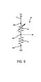
- Fig. 9 is a diagram showing an equivalent circuit for a pressure-sensitive device consisting of a resistor 40 and conducting member 50.
- the pressure-sensitive device is inserted in series in a power supply line 13, where the voltage V CC is applied between the electrodes 40a and 40b.
- the pressure-sensitive device is divided into a variable resistor 42 that has the relatively small resistance value of the conducting member 50, and a fixed resistor 41 that has the relatively large resistance value of the resistor 40.
- the portion of the variable resistor 42 is equivalent to the portion of resistance in the contact between the resistor 40 and the conducting member 50, so the resistance value of the pressure-sensitive device varies depending on the surface area of contact with the conducting member 50.
- Figs. 8A-8C show only the contact portion between the conducting member 50 and resistor 40 which forms the variable resistor 42 of Fig. 9, but the fixed resistor of Fig. 11 is omitted from Fig. 10.
- an output terminal is provided near the boundary between the variable resistor 42 and fixed resistor 41, namely near the intermediate point of the resistors 40, and thus a voltage stepped down from the applied voltage V CC by the amount the variable resistance is extracted as an analog signal corresponding to the pushing pressure by the user on the control button 221.
- the analog signal (voltage) output from the output terminal 40c of the resistor 40 reaches the maximum V max when the conducting member 50 is most deformed.
- Fig. 10 is a block diagram showing the main parts of the controller 200.
- An MPU 14 mounted on the internal board of the controller 200 is provided with a switch 18, an A/D converter 18 and two vibration generation systems.
- the analog signal (voltage) output from the output terminal 40c of the resistor 40 is provided as input to the A/D converter 16 and is converted to a digital signal.
- the digital signal output from the A/D converter 16 is sent via an interface 17 provided upon the internal board of the controller 200 to the entertainment system 500 and the actions of game characters and the like are executed based on this digital signal.
- Changes in the level of the analog signal output from the output terminal 40c of the resistor 40 correspond to changes in the pushing pressure received from the control button 221 (control element) as described above. Therefore, the digital signal outputted from the A/D converter 16 corresponds to the pushing pressure on the control button 221 (control element) from the user. If the actions of the game characters and the like are controlled based on the digital signal that has such a relationship with the pushing pressure from the user, it is possible to achieve smoother and more analog-like action than with control based on a binary digital signal based only on zeroes and ones.
- the configuration is such that the switch 18 is controlled by a control signal sent from the entertainment system 500 based on a game program recorded on an optical disc 411.
- a control signal is provided as output to specify whether the A/D converter 16 is to function as a means of providing output of a multi-valued analog signal, or as a means of providing a binary digital signal. Based on this control signal, the switch 18 is switched to select the function of the A/D converter 16.
- Each of the two vibration generation systems consists of a driver 19 which has a D/A converter that takes drive signals supplied from the entertainment system 500 via an interface 17, converts them to analog signals and amplifies them, a motor 20 driven by the output thereof, and an eccentric member 21 attached to the drive shaft of the motor 20.
- the eccentric member 21 is of a different size. This is intended to generate vibrations by its rotation.
- the vibration generation systems are to be described in detail later.
- Figs. 11 and 12 that show an example of the configuration of the first control part of the controller.
- the first control part 210 includes a cruciform control unit 211, a spacer 212 that positions this control unit 211, and an elastic body 213 that elastically supports the control unit 211.
- a conducting member 50 is attached to the rear surface of the elastic body 213, and the configuration is such that resistors 40 are disposed at the positions facing the individual control keys 211a (control elements) of the control unit 211 via the elastic body 213.
- the overall structure of the first control part 210 has already been made public knowledge in the publication of unexamined Japanese patent application No. JP-A-H8-163672.
- the control unit 211 uses a hemispherical projection 212a formed in the center of the spacer 212 as a fulcrum, and the individual control keys 211a (control elements) are assembled such that they can push on the resistor 40 side (see Fig. 12).
- Conducting members 50 are adhered to the inside of the top surface of the elastic body 213 in positions corresponding to the individual control keys 211 a (control elements) of the cruciform control unit 211.
- the resistors 40 with a single structure are disposed such that they face the individual conducting members 50.
- the pushing pressure acts via the elastic body 213 on the pressure-sensitive devices consisting of a conducting member 50 and resistor 40, so that its electrical resistance value varies depending on the magnitude of the pushing pressure.
- Fig. 13 is a diagram showing the circuit configuration of the resistor. As shown in this diagram, the resistor 40 is inserted in series in a power supply line 13, where a voltage is applied between the electrodes 40a and 40b. The resistance of this resistor 40 is illustrated schematically, as shown in this diagram, the resistor 40 is divided into first and second variable resistors 43 and 44.
- the portion of the first variable resistor 43 is in contact, respectively, with the conducting member 50 that moves together with the control key (up directional key) 211a for moving the character in the up direction, and with the conducting member 50 that moves together with the control key (left directional key) 211a for moving the character in the left direction, so its resistance value varies depending on the surface area in contact with these conducting members 50.
- the portion of the second variable resistor 44 is in contact, respectively, with the conducting member 50 that moves together with the control key (down directional key) 211a for moving the character in the down direction, and with the conducting member 50 that moves together with the control key (right directional key) 211a for moving the character in the right direction, so its resistance value varies depending on the surface area in contact with these conducting members 50.
- an output terminal 40c is provided intermediate between the variable resistors 43 and 44, and an analog signal corresponding to the pushing pressure on the individual control keys 211a (control elements) is provided as output from this output terminal 40c.
- Fig. 14 is a graph showing the characteristic of the analog signal (voltage) output from the output terminal of the resistor.
- the analog signal (voltage) output from the output terminal 40c of the resistor 40 reaches the maximum V max when the conducting member 50 is most deformed (at position q in the graph).
- the analog signal (voltage) output from the output terminal 40c of the resistor 40 reaches the minimum V min when the conducting member 50 is most deformed (at position s in the graph).
- the analog signal (voltage) output from the output terminal 40c of the resistor 40 is provided as input to an A/D converter 16 and converted to a digital signal.
- the function of the A/D converter 16 shown in Fig. 15 is as described previously based on Fig. 10, so a detailed description shall be omitted here.
- Fig. 16 is an exploded perspective view of the third control part of the controller.
- the third control part 230 consists of two control buttons 231, a spacer 232 for positioning these control buttons 231 within the interior of the controller 200, a holder 233 that supports these control buttons 231, an elastic body 234 and an internal board 235, having a structure wherein resistors 40 are attached to appropriate locations upon the internal board 235 and conducting members 50 are attached to the rear surface of the elastic body 234.
- the overall structure of the third control part 230 also already has been made public knowledge in the publication of unexamined Japanese patent application No. JP-A-H8-163672, so a detailed description thereof will be omitted.
- the individual control buttons 231 can be pushed in while being guided by the spacer 232, the pushing pressure when pressed acts via the elastic body 234 on the pressure-sensitive device consisting of a conducting member 50 and resistor 40.
- the electrical resistance value of the pressure-sensitive device varies depending on the magnitude of the pushing pressure it receives.
- the fourth control part 240 has the same structure as that of the third control part 230 described above.
- the vibration generation system mechanism 22 is disposed on the base sides of the first and second handle parts 10 and 11 which are held by the fingers of the user when the controller 200 is held.
- the vibration generation system mechanism 22 consists of a motor 20 driven by drive signals supplied from the entertainment system 500 and an eccentric member 21 attached to the driveshaft 20a of the motor 20.
- the eccentric member 21 is a metallic member having a large weight, and consists of a semicircular weight 21a which is eccentric with respect to a mating hole 20b which serves as the center of rotation when mated to the drive shaft 20a.
- the motor 20 with the eccentric member 21 attached to its drive shaft 20a is attached to the inside of the first handle part 10, mated to a motor housing 20c in a mating indentation 23 formed as a rectangular tube on the first handle part.
- the vibration generation system mechanisms 22 and 22 disposed on the first and second handle parts 10 and 11 are constituted such that the states of generation of vibrations thereof are different.
- the vibration generation system mechanisms 22 and 22 have different sizes of motors 20 and different eccentric members 21, so when driven by a fixed driving voltage, by making the speed of rotation different, the speed of rotation of the eccentric members 21 is made different, and the frequency of vibrations can be made to be different.
Abstract
Description
- The present invention relates to a computer system having a pressure-sensitive means and vibrating means, a method of using same and computer software for implementing this method.
- A known example of a computer under consideration is the entertainment system, such as a game machine which is a typical example. Controllers that have vibration motors have been proposed as the controllers currently used for video game machines. Such controllers equipped with vibration motors, have various vibration motors built into handles held by the user in the left and right hands.
- Such a controller is used for the feedback of various events during the game in the form of rotation of the vibration motors. Thereby, the user can feel a heightened sense of reality with these vibrations.
- For example, a pressure-sensitive type controller was disclosed in the publication of examined Japanese utility model application No. JP-B-H1-40545, wherein pressure-sensitive output is provided as an input to a VCO (variable control oscillator) and the output of the VCO is used for repeated fire in a game.
- US-5808540 describes a biofeedback device that causes vibrations in accordance with the pressure applied to a lever.
- US-5619180 describes a method of controlling a remote effect, e.g. the application of a forcer, in which feedback in the form of vibration is provided to the operator, the amplitude of the vibrations being based on the remote force applied.
- US-6225975 (JP-A-10 258181) discloses a controller for a gaming machine; the controller has a vibrator that is capable of vibrating and thereby causing the controller to vibrate.
- It is an object of the present invention to provide a controller which would be able itself to control vibrations of other controllers used in the video game machines.
- This and other objects of the present invention are attained by the computer-readable program, the method of controlling a computer system, a computer system and a computer program product as set out in the accompanying
independent claims -
- FIG. 1 is a schematic diagram of an example of connecting an entertainment system to a TV monitor to enable a user to enjoy game software or videos;
- Fig. 2 is a diagram showing a pressure-sensed value―drive signal conversion table for selecting various drive signals corresponding to various pressure-sensed values;
- Fig. 3 is a flowchart of a novel game process including a program for generating vibration depending on the pressure-sensed values;
- Fig. 4 is a diagram showing a controller connected to the entertainment system;
- Fig. 5 is a block diagram showing the entire entertainment system;
- Fig. 6 is a top view of the controller.
- Fig. 7 is an exploded perspective view of an embodiment of a second control part of the controller;
- Fig. 8A-8C are cross-sections through the second control part of Fig.7 showing an example of the constitution of the second control part.
- Fig. 9 shows an equivalent circuit for a pressure-sensitive device consisting of a resistor and conducting member;
- Fig. 10 is a block diagram showing the main parts of the controller;
- Fig. 11 is an exploded perspective view of a first control part of the controller;
- Fig. 12 is a sectional view through the first control part of the controller of Fig. 11;
- Fig. 13 diagrammatically shows the circuit configuration of a resistor;
- Fig. 14 is a graph showing the characteristic of the analog signal (voltage) output from the output terminal of the resistor of Fig. 13;
- Fig. 15 is a diagram showing the constitution wherein the analog signal (voltage) output from the resistor is provided as input to an A/D converter;
- Fig. 16 is an exploded perspective view of an embodiment of a third control part of the controller;
- Fig. 17 is a diagram showing the situation when the vibration generation system is disposed on the base sides of the first and second handle parts of the controller;
- Fig. 18 is an exploded perspective view of the vibration generation system;
- Fig. 19 is a perspective view of the vibration generation mechanism, consisting of a motor with an eccentric member attached to a driveshaft;
- Fig. 20 is a perspective view of the controllers showing that vibrations of the motor are transmitted via the side walls to the handle parts, and thus vibrations are transmitted to the user's fingers.
- In the preferred embodiment, when a controller having a pressure-sensitive device is operated, vibration depending on the pressure-sense value output at that time is output from a different controller. Thereby, it is possible to provide a chance to create games with an even broader range of ideas than the games that use the repetition of ON operations of an ON/OFF switch or the continuous operation thereof.
- Fig. 1 is a schematic diagram showing an example of connecting an
entertainment system 500 to aTV monitor 408 to enable a user to enjoy game software. More specific examples of the entertainment system are shown in Fig. 4. - As shown in Fig. 1, a
controller 200 which has buttons connected to pressure-sensitive devices and a vibration generator consisting of a motor and a rotating member which is attached to the shaft of the motor such that it is asymmetric to the center of the shaft is connected to theentertainment system 500 used for playing games or enjoying DVD video or other types of video images, and the video output terminals are connected to thetelevision monitor 408. - Here, the analog output from the pressure-sensitive devices is converted by an A/D converter to digital values in the range 0-255 and provided to the
entertainment system 500. In addition, based on a drive signal from theentertainment system 500, the aforementioned motor is driven and the aforementioned rotating member rotates, so that the vibration due to this rotation is transmitted to the player through the case of the controller. It is to be noted that thecontroller 200 equipped with a pressure-sensitive switch and the vibration generator will be described in detail below. - Here follows the description of the case of generating vibration by operation of the
controller 200, with reference to Figs. 2 and 3. - As an example, a head-to-head timing game which uses vibration generation will be now described. The game is played as follows. With two
controllers 200 connected to theentertainment system 500, when one of the two players pushes a pressure-serisitive switch, vibration is generated on theother controller 200. If desired, when one of the two players pushes a pressure-sensitive switch, vibration may be generated on both controllers 200 (one's own and the other player's). - In this state, when one player pushes the pressure-sensitive switch of his/her
controller 200, vibration is generated on the other player'scontroller 200. At this time, when vibration is generated on thecontroller 200 of the other player, the other player reacts and pushes the pressure-sensitive switch. The player is given points depending on the response speed at this time. - Fig. 2 shows a pressure-sensed value-drive signal conversion table for selecting a drive signal corresponding to each of the pressure-sensed values "0"-"255". Using this table, each pressure-sensed value is converted to a drive signal. The drive signals P1-P255 corresponding to each of the pressure-sense values are supplied from the
entertainment system 500 to thecontroller 200, and after conversion to analog signals by the A/D converter of thecontroller 200, they are given as drive signals for the motor of the vibration generator. It is to be noted that this conversion table is an example, and other tables may also be used. - The present invention can offer the following alternative example. In the working example, the pressure-sense value as pushed by the user is used as is. However, in order to compensate for differences in body strength among users and how good their reflexes are, the maximum value of the user pressure-sensed value can be corrected to a maximum game pressure-sense value set in the program, and the intermediate values can be corrected proportionally. This type of correction is performed by preparing a correction table.
- In addition, the user pressure-sensed value can be corrected based upon a known function and used as the game pressure-sensed value. This type of correction is performed by creating a correction table that is stored in an appropriate storage unit prepared in advance.
- Moreover, the maximum value of the user pressure-sensed value rate of change may be corrected to the maximum game pressure-sensed value rate of change set in the program, and intermediate values can be proportionally corrected and used. This type of correction is performed by creating a correction table. For more details about this method, reference is made to the present inventors' Japanese patent application No. 2000-40257 and the corresponding PCT application PCT/JP01/00136 (WO01/52037).
- Next, with reference to FIG. 3, a novel game including a program for generating vibration depending on the pressure-sensed values will be described. The flowchart shown in FIG. 3 shows the process of a game including a program for generating vibration depending on pressure-sensed values.
- The program for generating vibration depending on pressure-sensed values may be supplied either recorded alone on an optical disc or other recording medium, or recorded on the recording medium together with the game software as part of the game software. The program for generating vibration depending on pressure-sensed values is run by the
entertainment system 500 and executed by its CPU. - In FIG. 3, as shown in Step S1, a decision is made as to whether or not an input of pressure-sensed data is present, and if "YES" is the response then the control process moves to Step S2, where a pressure-sensed value is acquired from
controller 200. - The control process then moves to Step S3, where a decision is made as to whether or not the pressure-sensed value data of player A is nonzero, and if "YES" then the control procedure moves to Step S4, or if "NO" then the control procedure moves to Step S5.
- In Step S4, a drive signal corresponding to the pressure-sensed value from the
controller 200 of player A is read from the table shown in Fig. 2 and supplied to thecontroller 200 of player B. This drive signal is supplied to the motor of the vibration generator via the A/D converter ofcontroller 200 of player B. Thereby, vibration is generated by the vibration generator of thecontroller 200 of player B, and this is transmitted to player B via thecontroller 200 of player B. - In Step S5, a decision is made as to whether the pressure-sense value data of player B is nonzero or not, and if "YES" then control moves to Step S6, or if "NO" then control procedure moves to Step S7.
- In Step S6, a drive signal corresponding to the pressure-sense value from the
controller 200 of player B is read from the table of Fig. 2 and supplied to thecontroller 200 of player A. This drive signal is supplied to the motor of the vibration generator via the A/D converter of thecontroller 200 of player A. Thereby, vibration is generated by the vibration generator of thecontroller 200 of player A, and this is transmitted to player A via thecontroller 200 of player A. - In Step S7, a decision is made as to whether or not to end the control, and if "YES" then the control procedure moves to Step S8, and if "NO" then control procedure moves back to
Step S 1. - In Step S8, a decision is made as to whether or not input of pressure-sensed data is present, and if "YES" then the control procedure moves to Step S9, and if "NO" then the control procedure moves to Step S12. Here, the decision of whether or not input of pressure-sensed data is present refers to the input from the player where a decision of "none" is made in Step S3 or Step S5. For example, if a decision is made in Step S3 or Step S5 that the input from player A is present, then player A is determined to be the side generating vibration, namely the attacking side, so in Step S8, a decision is made as to whether or not the input is present from player B, which is the side for which a decision will be made about the timing of pushing the button depending on the vibration generated, so that if "YES" then the control procedure moves to Step S9 and if "NO" then control moves to Step S12. It is noted that the decision of whether or not the input is present may be taken over a stipulated length of time, for example, 3 seconds or the like.
- In Step S9, a stipulated value x is subtracted from the maximum value. The processing of this Step S9 has the meaning that the defending side, namely the player on the side reacting to the vibration generated by the other player, receives the maximum points decreased by the stipulated value x a number of times which is greater the slower the player's reactions are, thus decreasing the number of points earned.
- In Step S10, a decision as to whether or not to end the processing is made, and if "YES" then the control processing moves to Step S11, and if "NO" then the control process goes back to Step S1. This decision can be based on whether one of the players A or B has reached a stipulated point score or whether one of the players has pushed a stipulated button, directing the game to end, or the like.
- In Step S11, a screen indicating which player is the winner is displayed on the
television monitor 408. - In Step S12, a stipulated value x is subtracted from the maximum value. This is intended to convert into points the response time from when the attacking player (A or B) sends vibration to the other player until the defending player (B or A) to which the vibration is sent pushes the button in response. When the response is slow, the Steps S8 and S12 will loop several times, so that x is repetitively subtracted from the maximum number of points, and the number of points earned is low.
- As described above, in the present invention, a novel idea is that vibration depending on the pressure-sensed value is provided as an output from the other player's controller, and thus the scope of game creation can be broadened.
- For example, in the afore-described example, while this example relates to a game that uses the screen to certain extent, by allocating various vibration patterns to the increase or decrease of pressure-sensed values or to the pressure-sensed values themselves, it is possible to transmit one's wishes to the other party through a combination of vibrations, so it is possible to develop new software that can be used by seeing- or hearing-impaired persons, for example.
- Here follows an explanation of an embodiment of the present invention applied to the controller unit of a video game machine which is one example of a computer.
- Fig. 4 is a diagram showing the
controller 200 connected toentertainment system 500. Thecontroller 200 is removably connected to theentertainment system 500, and theentertainment system 500 is connected totelevision monitor 408. - The
entertainment system 500 reads the program for a computer game from recording media upon which that program is recorded, and by executing the program displays characters on thetelevision monitor 408. Theentertainment system 500 has also various built-in functions for DVD (Digital Versatile Disc) playback, CDDA (compact disc digital audio) playback and the like. The signals from thecontroller 200 are also processed as one of the aforementioned control functions within theentertainment system 500, and the content thereof may be reflected in the movement of characters and the like on thetelevision monitor 408. - While this depends also on the content of the computer game program,
controller 200 may be allocated functions for moving the characters displayed on thetelevision monitor 408 in the directions up, down, left or right. - With reference to Fig. 5, here follows a description of the interior of the
entertainment system 500 shown in Fig. 4. Fig. 5 is a block diagram of theentertainment system 500. - A
CPU 401 is connected to RAM 402 and abus 403, respectively. Connected tobus 403 are a graphics processor unit (GPU) 404 and an input/output processor (I/O) 409, respectively. - The
GPU 404 is connected via anencoder 407 for converting a digital RGB signal or the like into the NTSC standard television format, for example, to a television monitor (TV) 408 as a peripheral. Connected to the I/O 409 are a driver (DRV) 410 used for the playback and decoding of data recorded upon anoptical disc 411, a sound processor (SP) 412, anexternal memory 415 consisting of flash memory,controller 200 and aROM 416 which records the operating system and the like. TheSP 412 is connected via anamplifier 413 to aspeaker 414 as a peripheral. - Here, the
external memory 415 may be a card-type memory consisting of a CPU or a gate array and flash memory, which is removably connected via aconnector 511 to theentertainment system 500 shown in Fig. 4. - The
controller 200 is configured such that, when a plurality of buttons provided thereupon are pushed, it gives instructions to theentertainment system 500. In addition, thedriver 410 is provided with a decoder for decoding images encoded based upon the MPEG standard. - The description will be made now as to how the images will be displayed on the
television monitor 408 based on the operation ofcontroller 200. It is assumed that data for objects consisting of polygon vertex data, texture data and the like recorded on theoptical disc 411 is read by thedriver 410 and stored in theRAM 402 of theCPU 401. - When instructions from the player via
controller 200 are provided as an input to theentertainment system 500, theCPU 401 calculates the three-dimensional position and orientation of objects with respect to the point of view based on these instructions. Thereby, the polygon vertex data for objects defined by X, Y, Z coordinate values are modified variously. The modified polygon vertex data is subjected to perspective conversion processing and converted into two-dimensional coordinate data. - The regions specified by two-dimensional coordinates are so-called polygons. The converted coordinate data, Z data and texture data are supplied to the
GPU 404. Based on this converted coordinate data, Z data and texture data, theGPU 404 performs the drawing process by writing texture data sequentially into theRAM 405. One frame of image data upon which the drawing process is completed is encoded by theencoder 407 and then supplied to thetelevision monitor 408 and displayed on its screen as an image. - Fig. 6 is a top view of
controller 200. Thecontroller 200 consists of aunit body 201 on the top surface of which are provided first andsecond control parts fourth control parts controller 200. - The
first control part 210 of the controller is provided with acruciform control unit 211 used for pushing control, and theindividual control keys 211 a extending in each of the four directions of thecontrol unit 211 form a control element. Thefirst control part 210 is the control part for providing movement to the characters displayed on the screen of the television receiver, and has the functions for moving the characters in the up, down, left and right directions by pressing theindividual control keys 211 a of thecruciform control unit 211. - The
second control part 220 is provided with four cylindrical control buttons 221 (control elements) for pushing control. Theindividual control buttons 221 have identifying marks such as "○" (circle), "×" (cross), "Δ" (triangle) and "□" (quadrangle) on their tops, in order to easily identify theindividual control buttons 221. The functions of thesecond control part 220 are set by the game program recorded upon theoptical disc 411, and theindividual control buttons 221 may be allocated functions that change the state of the game characters, for example. - For example, the
control buttons 221 may be allocated functions for moving the left arm, right arm, left leg and right leg of the character. - The third and
fourth control parts control buttons 231 and 241 (control elements) for pushing control, arranged above and below. The functions of these third andfourth control parts - Moreover, two joy sticks 251 for performing analog operation are provided upon the
unit body 201 shown in Fig. 6. The joy sticks 251 can be switched and used instead of the first andsecond control parts analog selection switch 252 provided upon theunit body 201. When the joy sticks 251 are selected, adisplay lamp 253 provided on theunit body 201 lights, indicating the state wherein the joy sticks 251 are selected. - It is to be noted that on
unit body 201 there are also provided astart switch 254 for starting the game and aselect switch 255 for selecting the degree of difficulty or the like at the start of a game, and the like. - In Fig. 6, as indicated by broken lines, the
controller 200 is held by the left hand L and the right hand R and is operated by the other fingers, and in particular the thumbs L1 and R1 are able to operate most of the buttons on the top surface. - Fig. 7 and Figs. 8A-8C are, respectively, an exploded perspective view and cross-sectional views showing the second control part of the controller.
- As shown in Fig. 7, the
second control part 220 consists of fourcontrol buttons 221 which serve as the control elements, anelastic body 222, and asheet member 223 provided withresistors 40. Theindividual control buttons 221 are inserted from behind throughinsertion holes 201 a formed on the upper surface of theunit body 201. Thecontrol buttons 221 inserted into theinsertion holes 201a are able to move freely in the axial direction. - The
elastic body 222 is made of insulating rubber or the like and haselastic areas 222a which protrude upward, and the lower ends of thecontrol buttons 221 are supported upon the upper walls of theelastic areas 222a. When thecontrol buttons 221 are pressed, the inclined-surface portions of theseelastic areas 222a flex so that the upper walls move together with thecontrol buttons 221. - On the other hand, when the pushing pressure on the
control buttons 221 is released, the flexed inclined-surface portions of theseelastic areas 222a elastically return to their original shape, pushing up thecontrol buttons 221. Theelastic body 222 functions as a spring means wherebycontrol buttons 221 which had been pushed in by a pushing action are returned to their original positions. As shown in Figs. 8A-8C, conductingmembers 50 are attached to the rear surface of theelastic body 222. - The
sheet member 223 consists of a membrane or other thin sheet material which has flexibility and insulating properties.Resistors 40 are provided in appropriate locations on thissheet member 223 and theseresistors 40 and conductingmember 50 are each disposed such that they face one of thecontrol buttons 221 via theelastic body 222. Theresistors 40 and conductingmembers 50 form pressure-sensitive devices. These pressure-sensitive devices consisting ofresistors 40 and conductingmembers 50 have resistance values that vary depending on the pushing pressure received from thecontrol buttons 221. - To describe this in more detail, as shown in Fig. 8A-8C, the
second control part 220 is provided withcontrol buttons 221 as control elements, anelastic body 222, conductingmembers 50 andresistors 40. Each conductingmember 50 may be made of conductive rubber which has elasticity, for example, and has a conical shape with its center as a vertex. The conductingmembers 50 are adhered to the inside of the top surface of theelastic areas 222a formed in theelastic body 222. - In addition, the
resistors 40 may be provided on aninternal board 204, for example, opposite the conductingmembers 50, so that the conductingmembers 50 come into contact withresistors 40 together with the pushing action of thecontrol buttons 221. - The conducting
member 50 deforms depending on the pushing force on the control button 221 (namely the contact pressure with the resistor 40), so as shown in Figs. 8B and 8C, the surface area in contact with theresistor 40 varies depending on the pressure. To wit, when the pressing force on thecontrol button 221 is weak, as shown in Fig. 8B, only the area near the conical tip of the conductingmember 50 is in contact. As the pressing force on thecontrol button 221 becomes stronger, the tip of the conductingmember 50 deforms gradually so the surface area in contact expands. - Fig. 9 is a diagram showing an equivalent circuit for a pressure-sensitive device consisting of a
resistor 40 and conductingmember 50. As shown in this diagram, the pressure-sensitive device is inserted in series in apower supply line 13, where the voltage VCC is applied between theelectrodes variable resistor 42 that has the relatively small resistance value of the conductingmember 50, and a fixedresistor 41 that has the relatively large resistance value of theresistor 40. Among these, the portion of thevariable resistor 42 is equivalent to the portion of resistance in the contact between theresistor 40 and the conductingmember 50, so the resistance value of the pressure-sensitive device varies depending on the surface area of contact with the conductingmember 50. - To wit, when the conducting
member 50 comes into contact with theresistor 40, in the portion of contact, the conductingmember 50 becomes a bridge instead of theresistor 40 and a current flows, so the resistance value becomes smaller in the portion of contact. Therefore, the greater the surface area of contact between theresistor 40 and conductingmember 50, the lower the resistance value of the pressure-sensitive device becomes. In this manner, the entire pressure-sensitive device can be understood to be a variable resistor. Note that Figs. 8A-8C show only the contact portion between the conductingmember 50 andresistor 40 which forms thevariable resistor 42 of Fig. 9, but the fixed resistor of Fig. 11 is omitted from Fig. 10. - In the preferred embodiment, an output terminal is provided near the boundary between the
variable resistor 42 and fixedresistor 41, namely near the intermediate point of theresistors 40, and thus a voltage stepped down from the applied voltage VCC by the amount the variable resistance is extracted as an analog signal corresponding to the pushing pressure by the user on thecontrol button 221. - First, since a voltage is applied to the
resistor 40 when the power is turned on, even if thecontrol button 221 is not pressed, a fixed analog signal (voltage) Vmin is provided as the output from theoutput terminal 40c. Next, even if thecontrol button 221 is pressed, the resistance value of thisresistor 40 does not change until the conductingmember 50 contacts theresistor 40, so the output from theresistor 40 remains unchanged at Vmin. - If the
control button 221 is pushed further and the conductingmember 50 comes into contact with theresistor 40, the surface area of contact between the conductingmember 50 and theresistor 40 increases in response to the pushing pressure on thecontrol button 221, and thus the resistance of theresistor 40 is reduced so the analog signal (voltage) output from theoutput terminal 40c of theresistor 40 increases. - Furthermore, the analog signal (voltage) output from the
output terminal 40c of theresistor 40 reaches the maximum Vmax when the conductingmember 50 is most deformed. - Fig. 10 is a block diagram showing the main parts of the
controller 200. AnMPU 14 mounted on the internal board of thecontroller 200 is provided with aswitch 18, an A/D converter 18 and two vibration generation systems. The analog signal (voltage) output from theoutput terminal 40c of theresistor 40 is provided as input to the A/D converter 16 and is converted to a digital signal. - The digital signal output from the A/
D converter 16 is sent via aninterface 17 provided upon the internal board of thecontroller 200 to theentertainment system 500 and the actions of game characters and the like are executed based on this digital signal. - Changes in the level of the analog signal output from the
output terminal 40c of theresistor 40 correspond to changes in the pushing pressure received from the control button 221 (control element) as described above. Therefore, the digital signal outputted from the A/D converter 16 corresponds to the pushing pressure on the control button 221 (control element) from the user. If the actions of the game characters and the like are controlled based on the digital signal that has such a relationship with the pushing pressure from the user, it is possible to achieve smoother and more analog-like action than with control based on a binary digital signal based only on zeroes and ones. - The configuration is such that the
switch 18 is controlled by a control signal sent from theentertainment system 500 based on a game program recorded on anoptical disc 411. When a game program recorded on optical disc is executed by theentertainment system 500, depending on the content of the game program, a control signal is provided as output to specify whether the A/D converter 16 is to function as a means of providing output of a multi-valued analog signal, or as a means of providing a binary digital signal. Based on this control signal, theswitch 18 is switched to select the function of the A/D converter 16. - Each of the two vibration generation systems consists of a
driver 19 which has a D/A converter that takes drive signals supplied from theentertainment system 500 via aninterface 17, converts them to analog signals and amplifies them, amotor 20 driven by the output thereof, and aneccentric member 21 attached to the drive shaft of themotor 20. Theeccentric member 21 is of a different size. This is intended to generate vibrations by its rotation. The vibration generation systems are to be described in detail later. - Figs. 11 and 12 that show an example of the configuration of the first control part of the controller.
- As shown in Fig. 11, the
first control part 210 includes acruciform control unit 211, aspacer 212 that positions thiscontrol unit 211, and anelastic body 213 that elastically supports thecontrol unit 211. Moreover, as shown in Fig. 12, a conductingmember 50 is attached to the rear surface of theelastic body 213, and the configuration is such thatresistors 40 are disposed at the positions facing theindividual control keys 211a (control elements) of thecontrol unit 211 via theelastic body 213. - The overall structure of the
first control part 210 has already been made public knowledge in the publication of unexamined Japanese patent application No. JP-A-H8-163672. Thecontrol unit 211 uses ahemispherical projection 212a formed in the center of thespacer 212 as a fulcrum, and theindividual control keys 211a (control elements) are assembled such that they can push on theresistor 40 side (see Fig. 12). - Conducting
members 50 are adhered to the inside of the top surface of theelastic body 213 in positions corresponding to theindividual control keys 211 a (control elements) of thecruciform control unit 211. In addition, theresistors 40 with a single structure are disposed such that they face theindividual conducting members 50. - When the
individual control keys 211a which are control elements are pushed, the pushing pressure acts via theelastic body 213 on the pressure-sensitive devices consisting of a conductingmember 50 andresistor 40, so that its electrical resistance value varies depending on the magnitude of the pushing pressure. - Fig. 13 is a diagram showing the circuit configuration of the resistor. As shown in this diagram, the
resistor 40 is inserted in series in apower supply line 13, where a voltage is applied between theelectrodes resistor 40 is illustrated schematically, as shown in this diagram, theresistor 40 is divided into first and secondvariable resistors - Among these, the portion of the first
variable resistor 43 is in contact, respectively, with the conductingmember 50 that moves together with the control key (up directional key) 211a for moving the character in the up direction, and with the conductingmember 50 that moves together with the control key (left directional key) 211a for moving the character in the left direction, so its resistance value varies depending on the surface area in contact with these conductingmembers 50. - In addition, the portion of the second
variable resistor 44 is in contact, respectively, with the conductingmember 50 that moves together with the control key (down directional key) 211a for moving the character in the down direction, and with the conductingmember 50 that moves together with the control key (right directional key) 211a for moving the character in the right direction, so its resistance value varies depending on the surface area in contact with these conductingmembers 50. - Moreover, an
output terminal 40c is provided intermediate between thevariable resistors individual control keys 211a (control elements) is provided as output from thisoutput terminal 40c. - The output from the
output terminal 40c can be calculated from the ratio of the split in resistance value of the first and secondvariable resistors variable resistor 43, R2 is the resistance value of the secondvariable resistor 44 and VCC is the power supply voltage, then the output voltage V appearing at theoutput terminal 40c can be expressed by the following equation.
- Therefore, when the resistance value of the first
variable resistor 43 decreases, the output voltage increases, but when the resistance value of the secondvariable resistor 44 decreases, the output voltage also decreases. - Fig. 14 is a graph showing the characteristic of the analog signal (voltage) output from the output terminal of the resistor.
- First, since a voltage is applied to the
resistor 40 when the power is turned on, even if theindividual control keys 211a of thecontrol unit 211 are not pressed, a fixed analog signal (voltage) V0 is provided as output from theoutput terminal 40c (atposition 0 in the graph). - Next, even if one of the individual control keys 221a is pressed, the resistance value of this
resistor 40 does not change until the conductingmember 50 contacts theresistor 40, and the output from theresistor 40 remains unchanged at V0. - Furthermore, if the up directional key or left directional key is pushed until the conducting
member 50 comes into contact with the firstvariable resistor 43 portion of the resistor 40 (at position p in the graph), thereafter the surface area of contact between the conductingmember 50 and the firstvariable resistor 43 portion increases in response to the pushing pressure on thecontrol key 22 1 a (control elements), and thus the resistance of that portion is reduced so the analog signal (voltage) output from theoutput terminal 40c of theresistor 40 increases. - Furthermore, the analog signal (voltage) output from the
output terminal 40c of theresistor 40 reaches the maximum Vmax when the conductingmember 50 is most deformed (at position q in the graph). - On the other hand, if the down directional key or right directional key is pushed until the conducting
member 50 comes into contact with the secondvariable resistor 44 portion of the resistor 40 (at position r in the graph), thereafter the surface area of contact between the conductingmember 50 and the secondvariable resistor 44 portion increases in response to the pushing pressure on thecontrol key 211a (control elements), and thus the resistance of that portion is reduced, and as a result, the analog signal (voltage) output from theoutput terminal 40c of theresistor 40 decreases. - Furthermore, the analog signal (voltage) output from the
output terminal 40c of theresistor 40 reaches the minimum Vmin when the conductingmember 50 is most deformed (at position s in the graph). - As shown in Fig. 15, the analog signal (voltage) output from the
output terminal 40c of theresistor 40 is provided as input to an A/D converter 16 and converted to a digital signal. Note that the function of the A/D converter 16 shown in Fig. 15 is as described previously based on Fig. 10, so a detailed description shall be omitted here. - Fig. 16 is an exploded perspective view of the third control part of the controller.
- The
third control part 230 consists of twocontrol buttons 231, aspacer 232 for positioning thesecontrol buttons 231 within the interior of thecontroller 200, aholder 233 that supports thesecontrol buttons 231, anelastic body 234 and aninternal board 235, having a structure whereinresistors 40 are attached to appropriate locations upon theinternal board 235 and conductingmembers 50 are attached to the rear surface of theelastic body 234. - The overall structure of the
third control part 230 also already has been made public knowledge in the publication of unexamined Japanese patent application No. JP-A-H8-163672, so a detailed description thereof will be omitted. Theindividual control buttons 231 can be pushed in while being guided by thespacer 232, the pushing pressure when pressed acts via theelastic body 234 on the pressure-sensitive device consisting of a conductingmember 50 andresistor 40. The electrical resistance value of the pressure-sensitive device varies depending on the magnitude of the pushing pressure it receives. - It is noted that the
fourth control part 240 has the same structure as that of thethird control part 230 described above. - As shown in Fig. 17, the vibration
generation system mechanism 22 is disposed on the base sides of the first andsecond handle parts controller 200 is held. As shown in Fig. 18, the vibrationgeneration system mechanism 22 consists of amotor 20 driven by drive signals supplied from theentertainment system 500 and aneccentric member 21 attached to thedriveshaft 20a of themotor 20. - The
eccentric member 21 is a metallic member having a large weight, and consists of asemicircular weight 21a which is eccentric with respect to amating hole 20b which serves as the center of rotation when mated to thedrive shaft 20a. As shown in Fig. 19, themotor 20 with theeccentric member 21 attached to itsdrive shaft 20a is attached to the inside of thefirst handle part 10, mated to amotor housing 20c in amating indentation 23 formed as a rectangular tube on the first handle part. - With a vibration
generation system mechanism 22 having such a structure, when themotor 20 is driven theeccentric member 21 rotates and themotor 20 vibrates as shown in Fig. 20, and these vibrations are transmitted to thefirst handle part 10 through theside walls 23a which form themating indentation 23, and thus the vibrations are transmitted to the fingers holding thefirst handle part 10. - Here, the vibration
generation system mechanisms second handle parts generation system mechanisms motors 20 and differenteccentric members 21, so when driven by a fixed driving voltage, by making the speed of rotation different, the speed of rotation of theeccentric members 21 is made different, and the frequency of vibrations can be made to be different. - Due to the present invention, it is possible to control the vibrations themselves with the controller.
- Moreover, due to the present invention, it is possible to provide vibrations that depend on the pressure-sense values as output from the other player's controller, so the scope of game creation can be made much broader compared to the existing systems.
Claims (9)
- A computer-readable and executable program comprising computer code that, when run on a computer that is connected with a first controller (200) and at least one second controller (200), each controller having:pressure-sensitive means (211,221) that can provide an output in accordance with the pressure applied to it andvibrating means (19-21) that is able to vibrate,performs a step in which, the vibrating means (19-21) of said second controller (200) is caused to vibrate depending on the output of the pressure sensitive means (211,221) of said first controller (200) and a step in which the vibrating means (19-21) of said first controller (200) is caused to vibrate depending on the output of the pressure-sensitive means (211,221) of said second controller (200).
- The program according to claim 1, wherein the frequency of vibration of the vibrating means (19-21) of said second controller (200), is caused to vary depending on the rate of change per time unit of the value of the output of pressure sensitive means (211,221) of said first controller (200).
- A method of using a computer system having a first controller(200) having pressure-sensitive means (211,221) that can provide an output value in accordance with the pressure applied to it and vibrating means (19-21) that is able to vibrate, characterised in that the computer system includes at least one second controller (200), each said at least one second controller having pressure-sensitive means (211,221) that can provide an output value in accordance with the pressure applied to it and vibrating means (19-21) that is able to vibrate, wherein the method comprises:causing vibration in the vibrating means (19-21) of the second controller (200) on the basis of an output value from the pressure-sensitive means (211,221) of the first controller (200), andcausing vibration in the vibrating means (19-21) of said first controller (200) on the basis of the output value from the pressure-sensitive means (211,221) of second controller (200).
- The method according to claim 3, wherein, in said step of causing vibration in vibrating means (19-21) based on the output value from said pressure-sensitive means (211,221), the magnitude of said vibration is set in dependence on the magnitude of said output value.
- The method of using a computer according to claim 3, wherein the frequency of said vibration of the vibrating means (19-21) of one of the first and second controller (200) varies depending on the rate of change per time unit of the output value of the pressure sensitive means (211,221) of the other of the first and second controller (200).
- A computer system having a first controller (200) having a pressure-sensitive (211,221) means that can provide an output in accordance with the pressure applied to it and vibrating means (19-21) that is able to vibrate,
characterised in that the computer system further comprises:at least one second controller (200), controller each said at least one second having a pressure-sensitive means (211,221) that can provide an output in accordance with the pressure applied to it and vibrating means (19-21) that is able to vibrate,means for, based on an output value from the pressure-sensitivemeans (211,221) of said first controller (200), causing vibration in the vibrating means (19-21) of said second controller (200), andmeans for, based on the output value from the pressure-sensitive means (211,221) of said second controller (200), causing vibration in the vibrating means (19-21) of said first controller (200). - The computer system according to claim 6, wherein
said means for causing vibration in the vibrating means (19-21) includes means of setting the magnitude of said vibration in dependence on the magnitude of said output value. - The computer system according to claim 6 or claim 7 in the form of a video game machine.
- A computer program product comprising program code means stored on a computer readable medium for performing the steps of any one of claims 3 to 5 when said program product is run on a computer.
Applications Claiming Priority (3)
| Application Number | Priority Date | Filing Date | Title |
|---|---|---|---|
| JP2000040269 | 2000-01-14 | ||
| JP2000040269 | 2000-01-14 | ||
| PCT/JP2001/000150 WO2001052030A2 (en) | 2000-01-14 | 2001-01-12 | Computer with pressure-sensitive means, method of computer having a pressure-sensitive means and vibration means, method of using the same and recording medium for the method |
Publications (2)
| Publication Number | Publication Date |
|---|---|
| EP1247153A2 EP1247153A2 (en) | 2002-10-09 |
| EP1247153B1 true EP1247153B1 (en) | 2005-09-21 |
Family
ID=18563682
Family Applications (1)
| Application Number | Title | Priority Date | Filing Date |
|---|---|---|---|
| EP01900722A Expired - Lifetime EP1247153B1 (en) | 2000-01-14 | 2001-01-12 | Computer with pressure-sensitive means, method of computer having a pressure-sensitive means and vibration means, method of using the same and recording medium for the method |
Country Status (6)
| Country | Link |
|---|---|
| US (1) | US20010008849A1 (en) |
| EP (1) | EP1247153B1 (en) |
| JP (1) | JP2003519861A (en) |
| DE (1) | DE60113504D1 (en) |
| TW (1) | TW585797B (en) |
| WO (1) | WO2001052030A2 (en) |
Families Citing this family (25)
| Publication number | Priority date | Publication date | Assignee | Title |
|---|---|---|---|---|
| JP3370313B2 (en) * | 2000-07-17 | 2003-01-27 | コナミ株式会社 | GAME DEVICE, GAME MACHINE CONTROL METHOD, AND INFORMATION STORAGE MEDIUM |
| EP1406150A1 (en) * | 2002-10-01 | 2004-04-07 | Sony Ericsson Mobile Communications AB | Tactile feedback method and device and portable device incorporating same |
| US7798814B2 (en) * | 2003-02-14 | 2010-09-21 | Honda Motor Co., Ltd. | Riding simulation system |
| CN1759374A (en) * | 2003-03-12 | 2006-04-12 | 马特尔公司 | Interactive DVD gaming system |
| US8382567B2 (en) * | 2004-11-03 | 2013-02-26 | Mattel, Inc. | Interactive DVD gaming systems |
| US7331857B2 (en) * | 2004-11-03 | 2008-02-19 | Mattel, Inc. | Gaming system |
| JP5089079B2 (en) * | 2006-05-08 | 2012-12-05 | 任天堂株式会社 | Program, information storage medium, and image generation system |
| JP2007300974A (en) * | 2006-05-08 | 2007-11-22 | Nintendo Co Ltd | Program, information storage medium and image generation system |
| JP5030482B2 (en) * | 2006-06-20 | 2012-09-19 | 任天堂株式会社 | GAME PROGRAM AND GAME DEVICE |
| JP2009194597A (en) * | 2008-02-14 | 2009-08-27 | Sony Corp | Transmission and reception system, transmitter, transmission method, receiver, reception method, exhibition device, exhibition method, program, and recording medium |
| ES2585348T3 (en) * | 2010-03-29 | 2016-10-05 | Airbus Helicopters Deutschland GmbH | Flight simulator vibration system |
| WO2013069084A1 (en) * | 2011-11-07 | 2013-05-16 | 株式会社ソニー・コンピュータエンタテインメント | Manipulator and manipulation device |
| WO2016027331A1 (en) * | 2014-08-20 | 2016-02-25 | 慎司 西村 | Computer game simulated experience device |
| JP6625726B2 (en) | 2016-03-04 | 2019-12-25 | 株式会社ソニー・インタラクティブエンタテインメント | Control device and control program |
| JP6893763B2 (en) | 2016-06-10 | 2021-06-23 | 任天堂株式会社 | Game controller |
| JP6782567B2 (en) | 2016-06-10 | 2020-11-11 | 任天堂株式会社 | Game controller |
| JP6576432B2 (en) | 2016-06-10 | 2019-09-18 | 任天堂株式会社 | Game controller |
| JP7083226B2 (en) | 2016-06-10 | 2022-06-10 | 任天堂株式会社 | Game controller |
| JP6677580B2 (en) | 2016-06-10 | 2020-04-08 | 任天堂株式会社 | Game controller |
| EP3254739B1 (en) | 2016-06-10 | 2020-03-25 | Nintendo Co., Ltd. | Game controller |
| US10881953B2 (en) | 2016-07-21 | 2021-01-05 | Sony Interactive Entertainment Inc. | Operating device and control system |
| KR102171538B1 (en) | 2016-07-26 | 2020-10-29 | 주식회사 소니 인터랙티브 엔터테인먼트 | Information processing system, operating device, and operating device control method |
| JP6720310B2 (en) | 2016-07-26 | 2020-07-08 | 株式会社ソニー・インタラクティブエンタテインメント | Operating device and method for controlling operating device |
| US11173393B2 (en) * | 2017-09-29 | 2021-11-16 | Sony Interactive Entertainment Inc. | Operation device and control apparatus therefor |
| JP6949982B2 (en) | 2017-10-27 | 2021-10-13 | 株式会社ソニー・インタラクティブエンタテインメント | Operation device |
Family Cites Families (3)
| Publication number | Priority date | Publication date | Assignee | Title |
|---|---|---|---|---|
| US5451924A (en) * | 1993-01-14 | 1995-09-19 | Massachusetts Institute Of Technology | Apparatus for providing sensory substitution of force feedback |
| US5808540A (en) * | 1995-11-20 | 1998-09-15 | Wheeler; M. Rex | Position sensing and signaling system |
| JPH10258181A (en) * | 1997-03-18 | 1998-09-29 | Alps Electric Co Ltd | Operation device for game machine |
-
2001
- 2001-01-10 TW TW090100548A patent/TW585797B/en not_active IP Right Cessation
- 2001-01-10 US US09/757,812 patent/US20010008849A1/en not_active Abandoned
- 2001-01-12 WO PCT/JP2001/000150 patent/WO2001052030A2/en active IP Right Grant
- 2001-01-12 DE DE60113504T patent/DE60113504D1/en not_active Expired - Lifetime
- 2001-01-12 EP EP01900722A patent/EP1247153B1/en not_active Expired - Lifetime
- 2001-01-12 JP JP2001552183A patent/JP2003519861A/en active Pending
Also Published As
| Publication number | Publication date |
|---|---|
| JP2003519861A (en) | 2003-06-24 |
| WO2001052030A2 (en) | 2001-07-19 |
| WO2001052030A3 (en) | 2001-12-27 |
| US20010008849A1 (en) | 2001-07-19 |
| EP1247153A2 (en) | 2002-10-09 |
| TW585797B (en) | 2004-05-01 |
| DE60113504D1 (en) | 2005-10-27 |
Similar Documents
| Publication | Publication Date | Title |
|---|---|---|
| EP1247153B1 (en) | Computer with pressure-sensitive means, method of computer having a pressure-sensitive means and vibration means, method of using the same and recording medium for the method | |
| EP1255594B1 (en) | Method for changing viewpoints using pressure-sensitive means, recording medium providing software program therefor, and entertainment system | |
| JP3541030B2 (en) | Recording medium, method of using computer, and computer | |
| US20010009036A1 (en) | Method, recording medium, computer and controller for changing the settings various parameters of electronic equipment | |
| EP1218073B1 (en) | Communication optimisation for game machine | |
| US20010023204A1 (en) | Recording medium, computer, method for executing processes thereon, and method of selecting and executing processes on the computer | |
| EP1247156A2 (en) | Computer system having a pressure-sensitive controller, setup method for a pressure-sensitive controller and recording medium that records this method | |
| US20010008841A1 (en) | Recording medium, computer and method operating car images on a screen of the computer | |
| US20010009037A1 (en) | Recording medium recorded with a program that performs processing depending on a plurality of outputs from pressure-sensitive means, computer that executes the processing and method of using same | |
| US20010008397A1 (en) | Recording medium, method of entering items to be displayed and computer for executing the method | |
| WO2001052029A2 (en) | Method, recording medium, computer and controller for changing the settings of various parameters of electronic equipment | |
| US7027034B2 (en) | Method of moving objects on TV monitor, the computer and recording medium for executing the method | |
| US20010008403A1 (en) | Method, computer and recording medium for controlling message display quantity in game software | |
| JP2001259222A (en) | Recording medium wherein mah-jongg game using controller having pressure-sensitive means is stored, its computer and using method for computer |
Legal Events
| Date | Code | Title | Description |
|---|---|---|---|
| PUAI | Public reference made under article 153(3) epc to a published international application that has entered the european phase |
Free format text: ORIGINAL CODE: 0009012 |
|
| 17P | Request for examination filed |
Effective date: 20020507 |
|
| AK | Designated contracting states |
Kind code of ref document: A2 Designated state(s): AT BE CH CY DE DK ES FI FR GB GR IE IT LI LU MC NL PT SE TR |
|
| AX | Request for extension of the european patent |
Free format text: AL;LT;LV;MK;RO;SI |
|
| RBV | Designated contracting states (corrected) |
Designated state(s): DE GB |
|
| 17Q | First examination report despatched |
Effective date: 20040419 |
|
| GRAP | Despatch of communication of intention to grant a patent |
Free format text: ORIGINAL CODE: EPIDOSNIGR1 |
|
| GRAS | Grant fee paid |
Free format text: ORIGINAL CODE: EPIDOSNIGR3 |
|
| GRAA | (expected) grant |
Free format text: ORIGINAL CODE: 0009210 |
|
| AK | Designated contracting states |
Kind code of ref document: B1 Designated state(s): DE GB |
|
| REG | Reference to a national code |
Ref country code: GB Ref legal event code: FG4D |
|
| RIN1 | Information on inventor provided before grant (corrected) |
Inventor name: KOMATA, NOBUHIRO,SONY COMPUTER ENTERTAINMENT INC. |
|
| REF | Corresponds to: |
Ref document number: 60113504 Country of ref document: DE Date of ref document: 20051027 Kind code of ref document: P |
|
| PG25 | Lapsed in a contracting state [announced via postgrant information from national office to epo] |
Ref country code: DE Free format text: LAPSE BECAUSE OF FAILURE TO SUBMIT A TRANSLATION OF THE DESCRIPTION OR TO PAY THE FEE WITHIN THE PRESCRIBED TIME-LIMIT Effective date: 20051222 |
|
| PLBE | No opposition filed within time limit |
Free format text: ORIGINAL CODE: 0009261 |
|
| STAA | Information on the status of an ep patent application or granted ep patent |
Free format text: STATUS: NO OPPOSITION FILED WITHIN TIME LIMIT |
|
| 26N | No opposition filed |
Effective date: 20060622 |
|
| PGFP | Annual fee paid to national office [announced via postgrant information from national office to epo] |
Ref country code: GB Payment date: 20130109 Year of fee payment: 13 |
|
| GBPC | Gb: european patent ceased through non-payment of renewal fee |
Effective date: 20140112 |
|
| PG25 | Lapsed in a contracting state [announced via postgrant information from national office to epo] |
Ref country code: GB Free format text: LAPSE BECAUSE OF NON-PAYMENT OF DUE FEES Effective date: 20140112 |