EP1249213A2 - Method and device for pre-operative determination of the positional data of endoprosthetic parts - Google Patents
Method and device for pre-operative determination of the positional data of endoprosthetic parts Download PDFInfo
- Publication number
- EP1249213A2 EP1249213A2 EP02013129A EP02013129A EP1249213A2 EP 1249213 A2 EP1249213 A2 EP 1249213A2 EP 02013129 A EP02013129 A EP 02013129A EP 02013129 A EP02013129 A EP 02013129A EP 1249213 A2 EP1249213 A2 EP 1249213A2
- Authority
- EP
- European Patent Office
- Prior art keywords
- joint
- bones
- orientation
- determined
- processing system
- Prior art date
- Legal status (The legal status is an assumption and is not a legal conclusion. Google has not performed a legal analysis and makes no representation as to the accuracy of the status listed.)
- Withdrawn
Links
Images


Classifications
-
- A—HUMAN NECESSITIES
- A61—MEDICAL OR VETERINARY SCIENCE; HYGIENE
- A61B—DIAGNOSIS; SURGERY; IDENTIFICATION
- A61B5/00—Measuring for diagnostic purposes; Identification of persons
- A61B5/103—Detecting, measuring or recording devices for testing the shape, pattern, colour, size or movement of the body or parts thereof, for diagnostic purposes
- A61B5/107—Measuring physical dimensions, e.g. size of the entire body or parts thereof
-
- A—HUMAN NECESSITIES
- A61—MEDICAL OR VETERINARY SCIENCE; HYGIENE
- A61B—DIAGNOSIS; SURGERY; IDENTIFICATION
- A61B17/00—Surgical instruments, devices or methods, e.g. tourniquets
- A61B17/14—Surgical saws ; Accessories therefor
- A61B17/15—Guides therefor
-
- A—HUMAN NECESSITIES
- A61—MEDICAL OR VETERINARY SCIENCE; HYGIENE
- A61B—DIAGNOSIS; SURGERY; IDENTIFICATION
- A61B17/00—Surgical instruments, devices or methods, e.g. tourniquets
- A61B17/14—Surgical saws ; Accessories therefor
- A61B17/15—Guides therefor
- A61B17/154—Guides therefor for preparing bone for knee prosthesis
-
- A—HUMAN NECESSITIES
- A61—MEDICAL OR VETERINARY SCIENCE; HYGIENE
- A61B—DIAGNOSIS; SURGERY; IDENTIFICATION
- A61B34/00—Computer-aided surgery; Manipulators or robots specially adapted for use in surgery
- A61B34/20—Surgical navigation systems; Devices for tracking or guiding surgical instruments, e.g. for frameless stereotaxis
-
- A—HUMAN NECESSITIES
- A61—MEDICAL OR VETERINARY SCIENCE; HYGIENE
- A61B—DIAGNOSIS; SURGERY; IDENTIFICATION
- A61B5/00—Measuring for diagnostic purposes; Identification of persons
- A61B5/45—For evaluating or diagnosing the musculoskeletal system or teeth
- A61B5/4528—Joints
-
- A—HUMAN NECESSITIES
- A61—MEDICAL OR VETERINARY SCIENCE; HYGIENE
- A61B—DIAGNOSIS; SURGERY; IDENTIFICATION
- A61B90/00—Instruments, implements or accessories specially adapted for surgery or diagnosis and not covered by any of the groups A61B1/00 - A61B50/00, e.g. for luxation treatment or for protecting wound edges
- A61B90/10—Instruments, implements or accessories specially adapted for surgery or diagnosis and not covered by any of the groups A61B1/00 - A61B50/00, e.g. for luxation treatment or for protecting wound edges for stereotaxic surgery, e.g. frame-based stereotaxis
-
- A—HUMAN NECESSITIES
- A61—MEDICAL OR VETERINARY SCIENCE; HYGIENE
- A61B—DIAGNOSIS; SURGERY; IDENTIFICATION
- A61B90/00—Instruments, implements or accessories specially adapted for surgery or diagnosis and not covered by any of the groups A61B1/00 - A61B50/00, e.g. for luxation treatment or for protecting wound edges
- A61B90/36—Image-producing devices or illumination devices not otherwise provided for
-
- A—HUMAN NECESSITIES
- A61—MEDICAL OR VETERINARY SCIENCE; HYGIENE
- A61B—DIAGNOSIS; SURGERY; IDENTIFICATION
- A61B90/00—Instruments, implements or accessories specially adapted for surgery or diagnosis and not covered by any of the groups A61B1/00 - A61B50/00, e.g. for luxation treatment or for protecting wound edges
- A61B90/39—Markers, e.g. radio-opaque or breast lesions markers
-
- A—HUMAN NECESSITIES
- A61—MEDICAL OR VETERINARY SCIENCE; HYGIENE
- A61F—FILTERS IMPLANTABLE INTO BLOOD VESSELS; PROSTHESES; DEVICES PROVIDING PATENCY TO, OR PREVENTING COLLAPSING OF, TUBULAR STRUCTURES OF THE BODY, e.g. STENTS; ORTHOPAEDIC, NURSING OR CONTRACEPTIVE DEVICES; FOMENTATION; TREATMENT OR PROTECTION OF EYES OR EARS; BANDAGES, DRESSINGS OR ABSORBENT PADS; FIRST-AID KITS
- A61F2/00—Filters implantable into blood vessels; Prostheses, i.e. artificial substitutes or replacements for parts of the body; Appliances for connecting them with the body; Devices providing patency to, or preventing collapsing of, tubular structures of the body, e.g. stents
- A61F2/02—Prostheses implantable into the body
- A61F2/30—Joints
- A61F2/46—Special tools or methods for implanting or extracting artificial joints, accessories, bone grafts or substitutes, or particular adaptations therefor
- A61F2/4657—Measuring instruments used for implanting artificial joints
-
- G—PHYSICS
- G01—MEASURING; TESTING
- G01S—RADIO DIRECTION-FINDING; RADIO NAVIGATION; DETERMINING DISTANCE OR VELOCITY BY USE OF RADIO WAVES; LOCATING OR PRESENCE-DETECTING BY USE OF THE REFLECTION OR RERADIATION OF RADIO WAVES; ANALOGOUS ARRANGEMENTS USING OTHER WAVES
- G01S15/00—Systems using the reflection or reradiation of acoustic waves, e.g. sonar systems
- G01S15/87—Combinations of sonar systems
- G01S15/872—Combination of several systems for attitude determination
-
- G—PHYSICS
- G01—MEASURING; TESTING
- G01S—RADIO DIRECTION-FINDING; RADIO NAVIGATION; DETERMINING DISTANCE OR VELOCITY BY USE OF RADIO WAVES; LOCATING OR PRESENCE-DETECTING BY USE OF THE REFLECTION OR RERADIATION OF RADIO WAVES; ANALOGOUS ARRANGEMENTS USING OTHER WAVES
- G01S17/00—Systems using the reflection or reradiation of electromagnetic waves other than radio waves, e.g. lidar systems
- G01S17/87—Combinations of systems using electromagnetic waves other than radio waves
-
- G—PHYSICS
- G01—MEASURING; TESTING
- G01S—RADIO DIRECTION-FINDING; RADIO NAVIGATION; DETERMINING DISTANCE OR VELOCITY BY USE OF RADIO WAVES; LOCATING OR PRESENCE-DETECTING BY USE OF THE REFLECTION OR RERADIATION OF RADIO WAVES; ANALOGOUS ARRANGEMENTS USING OTHER WAVES
- G01S5/00—Position-fixing by co-ordinating two or more direction or position line determinations; Position-fixing by co-ordinating two or more distance determinations
- G01S5/16—Position-fixing by co-ordinating two or more direction or position line determinations; Position-fixing by co-ordinating two or more distance determinations using electromagnetic waves other than radio waves
- G01S5/163—Determination of attitude
-
- G—PHYSICS
- G01—MEASURING; TESTING
- G01S—RADIO DIRECTION-FINDING; RADIO NAVIGATION; DETERMINING DISTANCE OR VELOCITY BY USE OF RADIO WAVES; LOCATING OR PRESENCE-DETECTING BY USE OF THE REFLECTION OR RERADIATION OF RADIO WAVES; ANALOGOUS ARRANGEMENTS USING OTHER WAVES
- G01S5/00—Position-fixing by co-ordinating two or more direction or position line determinations; Position-fixing by co-ordinating two or more distance determinations
- G01S5/18—Position-fixing by co-ordinating two or more direction or position line determinations; Position-fixing by co-ordinating two or more distance determinations using ultrasonic, sonic, or infrasonic waves
- G01S5/186—Determination of attitude
-
- A—HUMAN NECESSITIES
- A61—MEDICAL OR VETERINARY SCIENCE; HYGIENE
- A61B—DIAGNOSIS; SURGERY; IDENTIFICATION
- A61B17/00—Surgical instruments, devices or methods, e.g. tourniquets
- A61B17/14—Surgical saws ; Accessories therefor
- A61B17/15—Guides therefor
- A61B17/154—Guides therefor for preparing bone for knee prosthesis
- A61B17/155—Cutting femur
-
- A—HUMAN NECESSITIES
- A61—MEDICAL OR VETERINARY SCIENCE; HYGIENE
- A61B—DIAGNOSIS; SURGERY; IDENTIFICATION
- A61B17/00—Surgical instruments, devices or methods, e.g. tourniquets
- A61B17/14—Surgical saws ; Accessories therefor
- A61B17/15—Guides therefor
- A61B17/154—Guides therefor for preparing bone for knee prosthesis
- A61B17/157—Cutting tibia
-
- A—HUMAN NECESSITIES
- A61—MEDICAL OR VETERINARY SCIENCE; HYGIENE
- A61B—DIAGNOSIS; SURGERY; IDENTIFICATION
- A61B17/00—Surgical instruments, devices or methods, e.g. tourniquets
- A61B2017/00017—Electrical control of surgical instruments
- A61B2017/00115—Electrical control of surgical instruments with audible or visual output
-
- A—HUMAN NECESSITIES
- A61—MEDICAL OR VETERINARY SCIENCE; HYGIENE
- A61B—DIAGNOSIS; SURGERY; IDENTIFICATION
- A61B17/00—Surgical instruments, devices or methods, e.g. tourniquets
- A61B2017/00681—Aspects not otherwise provided for
- A61B2017/00725—Calibration or performance testing
-
- A—HUMAN NECESSITIES
- A61—MEDICAL OR VETERINARY SCIENCE; HYGIENE
- A61B—DIAGNOSIS; SURGERY; IDENTIFICATION
- A61B34/00—Computer-aided surgery; Manipulators or robots specially adapted for use in surgery
- A61B34/10—Computer-aided planning, simulation or modelling of surgical operations
- A61B2034/107—Visualisation of planned trajectories or target regions
-
- A—HUMAN NECESSITIES
- A61—MEDICAL OR VETERINARY SCIENCE; HYGIENE
- A61B—DIAGNOSIS; SURGERY; IDENTIFICATION
- A61B34/00—Computer-aided surgery; Manipulators or robots specially adapted for use in surgery
- A61B34/20—Surgical navigation systems; Devices for tracking or guiding surgical instruments, e.g. for frameless stereotaxis
- A61B2034/2046—Tracking techniques
- A61B2034/2055—Optical tracking systems
-
- A—HUMAN NECESSITIES
- A61—MEDICAL OR VETERINARY SCIENCE; HYGIENE
- A61B—DIAGNOSIS; SURGERY; IDENTIFICATION
- A61B34/00—Computer-aided surgery; Manipulators or robots specially adapted for use in surgery
- A61B34/20—Surgical navigation systems; Devices for tracking or guiding surgical instruments, e.g. for frameless stereotaxis
- A61B2034/2068—Surgical navigation systems; Devices for tracking or guiding surgical instruments, e.g. for frameless stereotaxis using pointers, e.g. pointers having reference marks for determining coordinates of body points
-
- A—HUMAN NECESSITIES
- A61—MEDICAL OR VETERINARY SCIENCE; HYGIENE
- A61B—DIAGNOSIS; SURGERY; IDENTIFICATION
- A61B34/00—Computer-aided surgery; Manipulators or robots specially adapted for use in surgery
- A61B34/20—Surgical navigation systems; Devices for tracking or guiding surgical instruments, e.g. for frameless stereotaxis
- A61B2034/2072—Reference field transducer attached to an instrument or patient
-
- A—HUMAN NECESSITIES
- A61—MEDICAL OR VETERINARY SCIENCE; HYGIENE
- A61B—DIAGNOSIS; SURGERY; IDENTIFICATION
- A61B90/00—Instruments, implements or accessories specially adapted for surgery or diagnosis and not covered by any of the groups A61B1/00 - A61B50/00, e.g. for luxation treatment or for protecting wound edges
- A61B90/36—Image-producing devices or illumination devices not otherwise provided for
- A61B2090/363—Use of fiducial points
-
- A—HUMAN NECESSITIES
- A61—MEDICAL OR VETERINARY SCIENCE; HYGIENE
- A61B—DIAGNOSIS; SURGERY; IDENTIFICATION
- A61B90/00—Instruments, implements or accessories specially adapted for surgery or diagnosis and not covered by any of the groups A61B1/00 - A61B50/00, e.g. for luxation treatment or for protecting wound edges
- A61B90/39—Markers, e.g. radio-opaque or breast lesions markers
- A61B2090/3925—Markers, e.g. radio-opaque or breast lesions markers ultrasonic
- A61B2090/3929—Active markers
-
- A—HUMAN NECESSITIES
- A61—MEDICAL OR VETERINARY SCIENCE; HYGIENE
- A61B—DIAGNOSIS; SURGERY; IDENTIFICATION
- A61B90/00—Instruments, implements or accessories specially adapted for surgery or diagnosis and not covered by any of the groups A61B1/00 - A61B50/00, e.g. for luxation treatment or for protecting wound edges
- A61B90/39—Markers, e.g. radio-opaque or breast lesions markers
- A61B2090/3937—Visible markers
- A61B2090/3945—Active visible markers, e.g. light emitting diodes
-
- A—HUMAN NECESSITIES
- A61—MEDICAL OR VETERINARY SCIENCE; HYGIENE
- A61B—DIAGNOSIS; SURGERY; IDENTIFICATION
- A61B90/00—Instruments, implements or accessories specially adapted for surgery or diagnosis and not covered by any of the groups A61B1/00 - A61B50/00, e.g. for luxation treatment or for protecting wound edges
- A61B90/39—Markers, e.g. radio-opaque or breast lesions markers
- A61B2090/397—Markers, e.g. radio-opaque or breast lesions markers electromagnetic other than visible, e.g. microwave
- A61B2090/3975—Markers, e.g. radio-opaque or breast lesions markers electromagnetic other than visible, e.g. microwave active
- A61B2090/3979—Markers, e.g. radio-opaque or breast lesions markers electromagnetic other than visible, e.g. microwave active infrared
-
- A—HUMAN NECESSITIES
- A61—MEDICAL OR VETERINARY SCIENCE; HYGIENE
- A61B—DIAGNOSIS; SURGERY; IDENTIFICATION
- A61B90/00—Instruments, implements or accessories specially adapted for surgery or diagnosis and not covered by any of the groups A61B1/00 - A61B50/00, e.g. for luxation treatment or for protecting wound edges
- A61B90/39—Markers, e.g. radio-opaque or breast lesions markers
- A61B2090/3983—Reference marker arrangements for use with image guided surgery
-
- A—HUMAN NECESSITIES
- A61—MEDICAL OR VETERINARY SCIENCE; HYGIENE
- A61B—DIAGNOSIS; SURGERY; IDENTIFICATION
- A61B34/00—Computer-aided surgery; Manipulators or robots specially adapted for use in surgery
- A61B34/10—Computer-aided planning, simulation or modelling of surgical operations
-
- A—HUMAN NECESSITIES
- A61—MEDICAL OR VETERINARY SCIENCE; HYGIENE
- A61B—DIAGNOSIS; SURGERY; IDENTIFICATION
- A61B5/00—Measuring for diagnostic purposes; Identification of persons
- A61B5/68—Arrangements of detecting, measuring or recording means, e.g. sensors, in relation to patient
- A61B5/6846—Arrangements of detecting, measuring or recording means, e.g. sensors, in relation to patient specially adapted to be brought in contact with an internal body part, i.e. invasive
- A61B5/6867—Arrangements of detecting, measuring or recording means, e.g. sensors, in relation to patient specially adapted to be brought in contact with an internal body part, i.e. invasive specially adapted to be attached or implanted in a specific body part
- A61B5/6878—Bone
-
- A—HUMAN NECESSITIES
- A61—MEDICAL OR VETERINARY SCIENCE; HYGIENE
- A61B—DIAGNOSIS; SURGERY; IDENTIFICATION
- A61B90/00—Instruments, implements or accessories specially adapted for surgery or diagnosis and not covered by any of the groups A61B1/00 - A61B50/00, e.g. for luxation treatment or for protecting wound edges
- A61B90/06—Measuring instruments not otherwise provided for
-
- A—HUMAN NECESSITIES
- A61—MEDICAL OR VETERINARY SCIENCE; HYGIENE
- A61F—FILTERS IMPLANTABLE INTO BLOOD VESSELS; PROSTHESES; DEVICES PROVIDING PATENCY TO, OR PREVENTING COLLAPSING OF, TUBULAR STRUCTURES OF THE BODY, e.g. STENTS; ORTHOPAEDIC, NURSING OR CONTRACEPTIVE DEVICES; FOMENTATION; TREATMENT OR PROTECTION OF EYES OR EARS; BANDAGES, DRESSINGS OR ABSORBENT PADS; FIRST-AID KITS
- A61F2/00—Filters implantable into blood vessels; Prostheses, i.e. artificial substitutes or replacements for parts of the body; Appliances for connecting them with the body; Devices providing patency to, or preventing collapsing of, tubular structures of the body, e.g. stents
- A61F2/02—Prostheses implantable into the body
- A61F2/30—Joints
- A61F2/38—Joints for elbows or knees
-
- A—HUMAN NECESSITIES
- A61—MEDICAL OR VETERINARY SCIENCE; HYGIENE
- A61F—FILTERS IMPLANTABLE INTO BLOOD VESSELS; PROSTHESES; DEVICES PROVIDING PATENCY TO, OR PREVENTING COLLAPSING OF, TUBULAR STRUCTURES OF THE BODY, e.g. STENTS; ORTHOPAEDIC, NURSING OR CONTRACEPTIVE DEVICES; FOMENTATION; TREATMENT OR PROTECTION OF EYES OR EARS; BANDAGES, DRESSINGS OR ABSORBENT PADS; FIRST-AID KITS
- A61F2/00—Filters implantable into blood vessels; Prostheses, i.e. artificial substitutes or replacements for parts of the body; Appliances for connecting them with the body; Devices providing patency to, or preventing collapsing of, tubular structures of the body, e.g. stents
- A61F2/02—Prostheses implantable into the body
- A61F2/30—Joints
- A61F2/46—Special tools or methods for implanting or extracting artificial joints, accessories, bone grafts or substitutes, or particular adaptations therefor
- A61F2002/4632—Special tools or methods for implanting or extracting artificial joints, accessories, bone grafts or substitutes, or particular adaptations therefor using computer-controlled surgery, e.g. robotic surgery
- A61F2002/4633—Special tools or methods for implanting or extracting artificial joints, accessories, bone grafts or substitutes, or particular adaptations therefor using computer-controlled surgery, e.g. robotic surgery for selection of endoprosthetic joints or for pre-operative planning
-
- Y—GENERAL TAGGING OF NEW TECHNOLOGICAL DEVELOPMENTS; GENERAL TAGGING OF CROSS-SECTIONAL TECHNOLOGIES SPANNING OVER SEVERAL SECTIONS OF THE IPC; TECHNICAL SUBJECTS COVERED BY FORMER USPC CROSS-REFERENCE ART COLLECTIONS [XRACs] AND DIGESTS
- Y10—TECHNICAL SUBJECTS COVERED BY FORMER USPC
- Y10S—TECHNICAL SUBJECTS COVERED BY FORMER USPC CROSS-REFERENCE ART COLLECTIONS [XRACs] AND DIGESTS
- Y10S128/00—Surgery
- Y10S128/92—Computer assisted medical diagnostics
-
- Y—GENERAL TAGGING OF NEW TECHNOLOGICAL DEVELOPMENTS; GENERAL TAGGING OF CROSS-SECTIONAL TECHNOLOGIES SPANNING OVER SEVERAL SECTIONS OF THE IPC; TECHNICAL SUBJECTS COVERED BY FORMER USPC CROSS-REFERENCE ART COLLECTIONS [XRACs] AND DIGESTS
- Y10—TECHNICAL SUBJECTS COVERED BY FORMER USPC
- Y10S—TECHNICAL SUBJECTS COVERED BY FORMER USPC CROSS-REFERENCE ART COLLECTIONS [XRACs] AND DIGESTS
- Y10S623/00—Prosthesis, i.e. artificial body members, parts thereof, or aids and accessories therefor
- Y10S623/901—Method of manufacturing prosthetic device
Definitions
- the invention relates to a method for preoperative determination of the Position data of endoprosthesis parts of a middle joint relative to the bones forming the middle joint. Also concerns the invention an apparatus for performing this method.
- the procedure described can be applied to all parts of the body, in which the bones determining the joint to be replaced their other end also via a joint with additional bones are connected.
- the joint to be replaced is called the "middle one Joint "refers to the joints adjoining the outside as “outer joints".
- the External joints used to provide information about the preoperative Position of the bones adjoining the middle joint. It namely those that come together at the two outer joints Bones moved against each other, and by this movement the position of the outer joints is determined, more precisely joint points greater invariance. This is clear from the example of the leg, though the method described also used on all other links can be found where middle and outer joints are present are, for example on the arm.
- the middle joint is formed by the knee joint, the both outer joints through the hip joint and through the ankle joint.
- the hip joint is a ball joint, so that by moving the Thigh opposite the hip bone the center of this ball joint can be determined, i.e. a joint point of greatest invariance, that is, when the two bones move against each other immobile pivot point.
- the ankle is essentially a joint that only allows pivoting about a transverse axis, to a small extent is also a rotation about the longitudinal axis possible so that by superimposing these two pivoting movements a point can be determined with every movement of the ankle remains essentially motionless.
- knee joint If the knee joint is intact and still allows normal movements, you can also move the joint points near the knee with one movement of the two adjacent bones around this joint can be determined.
- the knee joint describes a relatively complicated unrolling Sliding movement, nevertheless, can be complicated when executing this superimposed movement and also when the Determine the lower leg around the vertical axis at which the movement when bending the knee becomes minimal, such a point maximum invariance is defined as the hinge point.
- hinge points can be used also by determining this at the middle Defines the joint by palpation of the articular surfaces.
- this area will be opened anyway and then the surgeon can Define certain striking points on the articular surfaces using buttons, for example between the two condyles. These are then called Hinge points determined.
- This contour of the articular surface can be opened the knee joint can be detected, for example, by a button, which is guided along the articular surface and which in different Positions along the articular surface corresponding to its position delivers to a data processing system. This can be based on this How to determine the contour of the articular surface, and based on this determined The surgeon can then define which point as the contour Hinge point of the middle joint is used.
- the articulation points are ideally determined solely by the kinematic determination the pivot points in the middle joint and in the two outer joints determined. Only in the case where the middle joint no longer permits such a provision due to damage, the described determination takes the place of the kinematic determination by palpation or by recording the contour of the articular surface. In any case, the location of the bone can be determined take place immediately before the actual operation, it is not necessary, complicated examinations in time before the operation perform.
- one for orientation of the endoprosthesis parts as Contact surfaces determined for these serving sawing planes, which are relative to adopt a predetermined orientation in the characteristic direction, in particular, these sawing planes can be perpendicular to the characteristic direction.
- the saw plane in a certain distance from that determined for the respective bone Articulation point is arranged on the middle joint. So that results a complete determination of the location and orientation of a such saw plane due to the kinematic described above Determination of the articulation points. However, this will not always be the case be practical, as it often only becomes clear during the operation how How far is a bone damaged in the joint area? the bone on the joint side must be removed.
- the inclination of the saw plane is relative to the characteristic Direction is determined, the distance from the joint is then through appropriate selection of different prosthesis parts of a set balanced or through documents between prosthesis part and bones are inserted.
- the surgeon has other options to compensate for this distance if necessary.
- the kinematic determination of the position of the Joint points made by the surgeon by making the bones of the limb moved against each other by hand.
- the Movement of the bones to determine the articulation points through a Drive device is executed.
- the two middle joint-forming bones and the two attached to the outer Joints adjacent bones each with marking elements be firmly connected, their position in the room by a measuring device is determined, the signals corresponding to this particular location generated and fed to a data processing system.
- a measuring device can be marking element and measuring devices, such as they are known per se from US-A-5,249,581, but here is from Meaning that both those connected to the middle joint Bones as well as the two attached to the outer joint Bones are connected with such marking elements that so there are at least four bones with three included joints where each bone is such a marker carries, so that at least the hinge points of the two outer Determine joints when the bones move relative to these joints can.
- the marking element and measuring device can be used as a marking element and measuring device
- radiation transmitters or several radiation receivers for example infrared radiation transmitter or ultrasound radiation transmitter and corresponding recipients.
- the marking elements can also be passive elements, for example reflecting spheres, onto those emitted by the measuring device Radiation falls and reflects off the surface of the sphere then is resumed by the measuring device. Essential is only that the measuring device the location of the marking elements in the room in a suitable way.
- the data obtained in this way in a characteristic direction and, if appropriate a sawing plane can be according to a preferred one Use embodiment of the invention to make a saw template relative to the characteristic direction of the bone aligns.
- This alignment can be done using a robot, for example be made by the position data of the data processing system is controlled.
- the differential signals can be tilted against each other Show lines that are parallel to each other when the orientation is correct run. It is beneficial if the lines intersect.
- this data processing system is designed such that that from the signals as the bones move around the two outer joints the points of greatest invariance are determined as joint points.
- the data processing system from the signals when the bones move around the middle Joint also the point of greatest invariance as the joint point of the middle joint determined.
- the Data processing system is assigned a keyboard instrument that his Positioning appropriate signals to the data processing system supplies.
- This keyboard instrument can be used, for example are opened at a certain point on the articular surface of the To feel joint and its position in space to the data processing system pass. Leave with this keyboard there are still a large number of points on the articular surface determine so that the entire course of a scanned joint surface can be passed on to the data processing system, which it can determine a data set from which the entire The course of the articular surface results.
- the keyboard can also use it on used orientation devices, for example Saw templates, the course of the contact surface for a saw blade to determine.
- the data processing system is designed so that it is out of position of the two hinge points of the two adjoining the middle hinge Bones each determine a characteristic direction for the bone.
- the data processing system for orientation the endoprosthesis parts as contact surfaces for this serving Saw planes determined relative to the characteristic direction adopt a predetermined orientation, in particular vertically stand in this characteristic direction.
- a drive device for moving the bones relative to the outer joints and possibly for movement includes relative to the central joint. This is the movement the bone around the respective joints mechanically and enables one fully automatic kinematic determination of the articulation points.
- the marking elements and the measuring device can act as radiation transmitters or radiation receiver.
- a robot can also be assigned to the device Tool template or tool relative to the characteristic Direction.
- a tool or a A marking element is assigned to the tool template, the Orientation is determined by the measuring device, so that this orientation appropriate signals to the data processing system be transmitted.
- the data processing system thus receives both the position signals of the bones as well as the position signals of the Tool or the tool template, so that the relative positioning can be monitored and controlled if necessary.
- FIG. 1 shows a patient 2 lying on an operating table 1 schematically shown, in which the knee joint 4 in a leg 3 to be replaced by an endoprosthesis.
- These marker elements 7, 8 comprise a foot 9 in which can be screwed into the bone Shape of a bone screw and a T-shaped attachment body 10, the spaced apart on its web 11 running parallel to the foot 9 to each other two radiation transmitters 12, 13 and on his to the web 11 subsequent crossbar 14 also two radiation transmitters 15, 16 wearing.
- These radiation transmitters can be, for example, ultraviolet diodes be or ultrasound transmitter.
- the attachment body 10 can be detachably on the Foot 9 be put on, but only in a very specific position can be placed relative to the foot 9, so that even after Removal and after reattaching such a body 10, the radiation transmitters 12, 13, 15, 16 are exactly the same relative to the bone Take position as before removing.
- Such marking elements 17 and 18 are not only on the thigh 5 and 6 on the lower leg, but also on the hip bone 19 and on the foot bone 20.
- a console 21 On a console 21 are three receiving devices at a distance from each other 22, 23, 24 arranged that receive the radiation that are emitted by the radiation transmitters 12, 13, 15, 16. At the The receiving devices generate electrical reception of radiation Signals that are fed to a data processing system 25. Due to the different orientation of marking elements and receiving devices there are differences in transit times between sending and receiving the radiation, and because of this The data processing system 25 can have runtime differences each marking element 7, 8, 17, 18 its position in space completely determine and save this location data. It is because of it possible to generate data sets in the data processing system the location of the marking elements and thus the position of the fixed elements Bones match at certain times.
- the receiving devices 22, 23, 24 can be in different Be designed, they can, as described, the orientation determine the marking elements by differences in transit time, in principle, it would also be possible to determine the orientation by geometrically measuring the beam direction of radiation from the radiation transmitters 12, 13, 15, 16 is emitted. With others Refinements can also be used, which do not have radiation transmitters, but reflecting surfaces, reflecting radiation emitted by the receiving device becomes. These reflection surfaces can be spherical, for example to have.
- the point of maximum approximation of this Curves can be defined as an articulation point, which is in the described Movement of the femur in relation to the Finding the lower leg bone.
- Such a calculation is also used performed by the data processing system 25, so that on this Way the data processing system both in the area of the ankle as well as in the area of the hip joint and finally also in the area of the knee joint can determine such joint points.
- the data processing system 25 calculates a characteristic one Direction for the lower leg, which is made up of a straight line Connection of the joint point in the knee and the joint point in the Ankle results in the same way for the thigh characteristic direction determined, which results from the rectilinear Connection of the joint point in the knee and the joint point in the Hip results.
- characteristic directions do not necessarily have to be coincide with the actual course of the bone, it is a question of virtual directions that arise solely from the result in kinematic data.
- the data processing system determines from the characteristic thus obtained Directions the orientation of these sawing planes 26, 27, which are preferably perpendicular to the characteristic directions. This is indicated schematically in FIG. 3.
- the orientation of the Saw planes become relative to the orientation of the marking elements 7 and 8 calculated, which in turn represent the orientation of the thigh 5 and the lower leg 6 are.
- Saw plane data can now be used, for example align a saw template 28 relative to a bone.
- this is shown schematically on the basis of the femur 5.
- the thigh bone 5 carries the marking element 7, see above that its location in the room can be determined in the manner described can.
- a saw template 28 also carries a marking element 29, see above that the location of the saw template 28 in the room at any time on the Data processing system 25 can be determined.
- the saw template 28 has a flat guide surface 30 for a saw blade 31, the position the guide surface 30 relative to the marking element 29 can be in determine easily by using a calibrated, hand-held Probe element, the guide surface 30 is mapped.
- a marking element connected to the keyboard reports all position data of the touch element to the data processing system, which in this way take up the data of the area can be moved from the tip of the probe. After such a calibration, the data processing system is ready the data is available to help from the orientation of the marking element 29 to calculate the orientation of the guide surface 30.
- the Guide surface 30 are oriented so that they are perpendicular to the characteristic direction of the femur stands, and this can be accomplished relatively easily by the data processing system 25 a difference signal is generated, which of Deviation of the orientation of the guide surface 30 from the orientation corresponds to the calculated saw plane 26.
- a difference signal can be perceived by the surgeon in various ways be designed.
- a monitor 32 is located on the console 21, for example arranged on which graphical representations are mapped which are a measure of this difference signal.
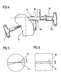
- a possible difference signal can, for example, by the inclination of two straight lines 33, 34 are reproduced against each other ( Figure 5), preferably the angle of inclination of the two lines the angle of deviation of the saw plane 26 corresponds to the guide surface 30 in one direction.
- the difference signal represented by the distance between two parallel lines 35, 36 ( Figure 6). If these two lines 35, 36 coincide, there is no more difference signal, then guide surface 30 and saw plane 26 oriented in the corresponding direction as desired. It is advantageous if the display according to FIG. 5 and the display combined according to FIG. 6, the display according to FIG. 5 and the display according to FIG. 6 then shows the inclination of the saw plane 26 relative to the guide surface 30 in mutually perpendicular Directions. If in both juxtapositions the difference signal has disappeared, the saw template 28 oriented as desired, this orientation can then, for example can be fixed by hammered guide pins 37.
- the described manual orientation of the saw template 28 can of course in another embodiment of the invention also be done by a robot that is operated by the data processing system 25 controlled according to the data records available there is that the guide surface 30 extends parallel to the saw plane 26.
- the surgeon can now prepare for the operation now by guiding the saw blade 31 along the guide surface 30 separate the bone with the desired orientation so that thereby a contact surface for a not shown in the drawing Prosthesis part is created.
- This prosthesis part takes place when it is attached to it The desired orientation relative to the bone, so that in this way a very exact positioning of prosthesis parts on the bone.
- both are connected to the joint to be replaced Bone proceeded so that both prosthesis parts in the can be positioned as desired.
Abstract
Description
Die Erfindung betrifft ein Verfahren zur präoperativen Bestimmung der Positionsdaten von Endoprothesenteilen eines mittleren Gelenkes relativ zu den das mittlere Gelenk ausbildenden Knochen. Außerdem betrifft die Erfindung eine Vorrichtung zur Durchführung dieses Verfahrens.The invention relates to a method for preoperative determination of the Position data of endoprosthesis parts of a middle joint relative to the bones forming the middle joint. Also concerns the invention an apparatus for performing this method.
Bei chirurgischen Operationen, bei denen Gelenke zwischen zwei Knochen durch Endoprothesen ersetzt werden müssen, ist es äußerst wichtig, daß die Endoprothesenteile relativ zu den Knochen exakt positioniert werden, Abweichungen in der Größenordnung von mehr als 2° stellen den Erfolg einer solchen Operation bereits infrage.In surgical operations where joints are between two bones must be replaced by endoprostheses, it is extreme it is important that the endoprosthesis parts are positioned exactly in relation to the bones deviations of the order of more than 2 ° are already questioning the success of such an operation.
Es ist bekannt, zur Vorbereitung von chirurgischen Operationen die Lage von Knochen im Körper und die relative Positionierung der an das zu ersetzende Gelenk angrenzenden Knochen durch verschiedene Verfahren zu bestimmen, um vor der Operation bereits planen zu können, wie die Endoprothesenteile relativ zu den Knochen eingesetzt werden müssen. Beispielsweise ist es bekannt, die Außenkontur der an das zu ersetzende Gelenk angrenzenden Knochen durch Computertomographieaufnahmen zu bestimmen, anhand der so gewonnenen Daten lassen sich Datensätze erstellen, die den Außenkonturen der Knochen entsprechen und die dann zur Planung der Orientierung der Prothesenteile benutzt werden können (M. Fadda et al "Computer-Assisted Knee Arthoplasty at Rizzoli Institute"; MRCAS 94, Medical Robotics and Computer Assisted Surgery, Pittsburgh, 1994, Seiten 26 bis 31; T. C. Kienzle III et al "A Computer-Assisted Total Knee Replacement Surgical System Using a Calibrated Robot", MIT Press, Cambridge, MA, 1996, Seiten 409 bis 416).It is known to prepare for surgical operations Location of bones in the body and the relative positioning of the at the Joint to be replaced adjacent bone by various methods to determine in order to be able to plan before the operation, how the endoprosthesis parts are used relative to the bones have to. For example, it is known that the outer contour of the to replacing joint adjacent bones by computer tomography to determine, based on the data obtained in this way create records that match the outer contours of the bones correspond and then to plan the orientation of the prosthesis parts can be used (M. Fadda et al "Computer-Assisted Knee Arthoplasty at Rizzoli Institute "; MRCAS 94, Medical Robotics and Computer Assisted Surgery, Pittsburgh, 1994, pages 26-31; T. C. Kienzle III et al "A Computer-Assisted Total Knee Replacement Surgical System Using a Calibrated Robot ", MIT Press, Cambridge, MA, 1996, Pages 409 to 416).
Dies setzt eine komplizierte Untersuchung des Patienten vor Beginn der Operation voraus, die häufig nicht am eigentlichen Operationsort und daher in der Regel auch nicht zeitgleich mit der Operation durchgeführt werden kann. Außerdem muß der Patient dabei einer hohen Strahlendosis ausgesetzt werden, schließlich sind für diese Untersuchung teure apparative Ausstattungen notwendig.This implies a complicated examination of the patient before starting ahead of the operation, which is often not at the actual operating site and therefore usually not performed at the same time as the operation can be. In addition, the patient must have a high Radiation dose are finally exposed for this investigation expensive equipment required.
Es ist bereits bekannt, die Lage der Knochen vor und nach der Operation dadurch miteinander zu vergleichen, daß an den Knochen Markierungselemente befestigt werden, deren Position im Raum durch geeignete kamera-ähnliche Vorrichtungen bestimmt werden kann (US-A-5,249,581). Mit einer solchen Vorrichtung kann das Ergebnis der Operation geprüft werden, denn der Operateur kann die Orientierung der Knochen vor und nach der Operation vergleichen. Es ist jedoch mit diesem Verfahren nicht möglich, präoperativ die Positionsdaten der einzusetzenden Prothesenteile zu bestimmen, auch bei diesem Verfahren muß die Lage der Prothesenteile am Knochen präoperativ dadurch bestimmt werden, daß zum Beispiel durch Computertomographie-Aufnahmen die genaue Lage der Knochen im Körper und ihre Relativpositionierung zueinander bestimmt werden. It is already known the location of the bones before and after the operation to compare with each other that on the bones marking elements be fixed, their position in the room by suitable camera-like devices can be determined (US-A-5,249,581). With such a device, the result of the operation be checked, because the surgeon can change the orientation of the Compare bones before and after surgery. However, it is with this Procedure not possible preoperatively the position data of the one to be used Determine prosthetic parts, also with this procedure the position of the prosthesis parts on the bone must be determined preoperatively be that, for example, by computer tomography the exact position of the bones in the body and their relative positioning can be determined to each other.
Es ist Aufgabe der Erfindung, ein Verfahren anzugeben, mit dem präoperativ die Lage der Prothesenteile relativ zu dem Knochen bestimmt werden kann, ohne daß dazu komplizierte Untersuchungsverfahren des Patienten notwendig werden, insbesondere sollen CT-Aufnahmen oder ähnliche Untersuchungsverfahren überflüssig werden.It is an object of the invention to provide a method with which preoperatively determines the position of the prosthesis parts relative to the bone can be done without complicated examination procedures of the Patients should be necessary, especially CT scans or similar test methods become superfluous.
Diese Aufgabe wird durch das Verfahren gemäß Anspruch 1 gelöst.This object is achieved by the method according to claim 1.
Das beschriebene Verfahren läßt sich an allen Körperteilen anwenden, bei denen die das zu ersetzende Gelenk bestimmenden Knochen an ihrem anderen Ende ebenfalls über ein Gelenk mit weiteren Knochen verbunden sind. Nachfolgend wird das zu ersetzende Gelenk als "mittleres Gelenk" bezeichnet, die außenseitig anschließenden Gelenke als "äußere Gelenke". Bei dem beschriebenen Verfahren werden nun die äußeren Gelenke dazu verwendet, präoperativ Informationen über die Lage der am mittleren Gelenk anschließenden Knochen zu liefern. Es werden nämlich die an den beiden äußeren Gelenken zusammenkommenden Knochen gegeneinander bewegt, und durch diese Bewegung wird die Lage der äußeren Gelenke bestimmt, genauer Gelenkpunkte größer Invarianz. Dies wird am Beispiel des Beines deutlich, obwohl das beschriebenen Verfahren auch an allen anderen Gliedern verwendet werden kann, bei denen mittlere und äußere Gelenke vorhanden sind, beispielsweise am Arm.The procedure described can be applied to all parts of the body, in which the bones determining the joint to be replaced their other end also via a joint with additional bones are connected. In the following, the joint to be replaced is called the "middle one Joint "refers to the joints adjoining the outside as "outer joints". In the described method, the External joints used to provide information about the preoperative Position of the bones adjoining the middle joint. It namely those that come together at the two outer joints Bones moved against each other, and by this movement the position of the outer joints is determined, more precisely joint points greater invariance. This is clear from the example of the leg, though the method described also used on all other links can be found where middle and outer joints are present are, for example on the arm.
Beim Bein wird das mittlere Gelenk durch das Kniegelenk gebildet, die beiden äußeren Gelenke durch das Hüftgelenk und durch das Fußgelenk. Das Hüftgelenk ist ein Kugelgelenk, so daß durch Bewegung des Oberschenkels gegenüber dem Hüftknochen der Mittelpunkt dieses Kugelgelenks bestimmt werden kann, also ein Gelenkpunkt größter Invarianz, das heißt ein bei der Bewegung der beiden Knochen gegeneinander unbeweglicher Gelenkpunkt.In the leg, the middle joint is formed by the knee joint, the both outer joints through the hip joint and through the ankle joint. The hip joint is a ball joint, so that by moving the Thigh opposite the hip bone the center of this ball joint can be determined, i.e. a joint point of greatest invariance, that is, when the two bones move against each other immobile pivot point.
In ähnlicher Weise läßt sich auch beim Fußgelenk ein solcher Punkt größter Invarianz bestimmen. Zwar ist das Fußgelenk im wesentlichen ein Gelenk, das nur eine Verschwenkung um eine Querachse ermöglicht, in geringem Umfange ist aber auch eine Drehung um die Längsachse möglich, so daß durch die Überlagerung dieser beiden Schwenkbewegungen ein Punkt bestimmt werden kann, der bei jeder Bewegung des Fußgelenkes im wesentlichen unbewegt bleibt.In a similar way, such a point can also be applied to the ankle determine greatest invariance. The ankle is essentially a joint that only allows pivoting about a transverse axis, to a small extent is also a rotation about the longitudinal axis possible so that by superimposing these two pivoting movements a point can be determined with every movement of the ankle remains essentially motionless.
Im Bereich des Knies werden zusätzlich in ähnlicher Weise Gelenkpunkte bestimmt, wobei dafür dem Chirurgen verschiedene Methoden zur Verfügung stehen können.In the area of the knee joint points are also created in a similar way determined, using different methods for the surgeon can be available.
Wenn das Kniegelenk intakt ist und noch normale Bewegungen ermöglicht, können auch die knienahen Gelenkpunkte durch eine Bewegung der beiden angrenzenden Knochen um dieses Gelenk bestimmt werden. Zwar beschreibt das Kniegelenk eine relativ komplizierte Abrollund Gleitbewegung, trotzdem lassen sich bei Ausführung dieser komplizierten überlagerten Bewegung und außerdem bei einer Drehung des Unterschenkels um die senkrechte Achse Punkte bestimmen, bei denen die Bewegung beim Beugen des Knies minimal wird, ein solcher Punkt maximaler Invarianz wird als Gelenkpunkt definiert.If the knee joint is intact and still allows normal movements, you can also move the joint points near the knee with one movement of the two adjacent bones around this joint can be determined. The knee joint describes a relatively complicated unrolling Sliding movement, nevertheless, can be complicated when executing this superimposed movement and also when the Determine the lower leg around the vertical axis at which the movement when bending the knee becomes minimal, such a point maximum invariance is defined as the hinge point.
Gemäß einer anderen Ausführungsform der Erfindung kann man Gelenkpunkte auch dadurch bestimmen, daß man diese am mittleren Gelenk durch Palpation der Gelenkflächen festlegt. Bei der Ersetzung eines mittleren Gelenkes, also beispielsweise des Kniegelenkes, muß dieser Bereich ohnehin eröffnet werden, und dann kann der Chirurg durch Tasten bestimmte markante Punkte der Gelenkflächen festlegen, beispielsweise zwischen den beiden Kondylen. Diese werden dann als Gelenkpunkte bestimmt.According to another embodiment of the invention, hinge points can be used also by determining this at the middle Defines the joint by palpation of the articular surfaces. When replacing a middle joint, for example the knee joint this area will be opened anyway and then the surgeon can Define certain striking points on the articular surfaces using buttons, for example between the two condyles. These are then called Hinge points determined.
Es ist auch möglich, bei einer anderen Ausführungsform der Erfindung die Gelenkpunkte der Knochen am mittleren Gelenk aus einem Datensatz zu bestimmen, der die Kontur der Gelenkfläche am mittleren Gelenk wiedergibt. Diese Kontur der Gelenkfläche kann nach dem Eröffnen des Kniegelenks beispielsweise durch einen Taster erfaßt werden, der an der Gelenkfläche entlanggeführt wird und der in verschiedenen Stellungen längs der Gelenkfläche seiner Position entsprechende Signale an eine Datenverarbeitungsanlage liefert. Diese kann auf diese Weise die Kontur der Gelenkfläche bestimmen, und anhand dieser bestimmten Kontur kann der Chirurg dann festlegen, welcher Punkt als Gelenkpunkt des mittleren Gelenkes verwendet wird.It is also possible in another embodiment of the invention the joint points of the bones at the middle joint from a data set to determine the contour of the articular surface at the middle joint reproduces. This contour of the articular surface can be opened the knee joint can be detected, for example, by a button, which is guided along the articular surface and which in different Positions along the articular surface corresponding to its position delivers to a data processing system. This can be based on this How to determine the contour of the articular surface, and based on this determined The surgeon can then define which point as the contour Hinge point of the middle joint is used.
Als Resultat dieser Bestimmung der Gelenkpunkte in den beiden äußeren Gelenken und im mittleren Gelenk lassen sich für jeden der beiden das mittlere Gelenk bildenden Knochen charakteristische Richtungen bestimmen, indem die beiden Gelenkpunkte jedes Knochens geradlinig miteinander verbunden werden. Diese charakteristischen Richtungen werden dann zur Orientierung der Prothesenteile herangezogen, das heißt anhand dieser charakteristischen Richtung wird die Neigung der Prothesenteile bestimmt, unter der diese in den Knochen eingebaut werden sollen.As a result of this determination of the hinge points in the two outer Joints and in the middle joint can be used for either of the two characteristic bones forming the middle joint determine by straightening the two hinge points of each bone be connected to each other. These characteristic directions are then used to orient the prosthesis parts is called on the basis of this characteristic direction the inclination of the Prosthesis parts determined under which these are built into the bone should be.
Zur Bestimmung dieser charakteristischen Richtung ist es nicht notwendig, den Knochen in seiner Gesamtkontur vorher zu bestimmen, beispielsweise durch eine Computertomographie, sondern die Gelenkpunkte werden im Idealfall ausschließlich durch die kinematische Bestimmung der Gelenkpunkte im mittleren Gelenk und in den beiden äußeren Gelenken bestimmt. Nur in dem Fall, in dem das mittlere Gelenk eine solche Bestimmung durch Beschädigung nicht mehr zuläßt, tritt an die Stelle der kinematischen Bestimmung die beschriebene Bestimmung durch Palpation oder durch Aufnahme der Kontur der Gelenkfläche. In jedem Fall kann die Bestimmung der Lage des Knochens unmittelbar vor der eigentlichen Operation stattfinden, es ist nicht notwendig, in zeitlichem Abstand vor der Operation komplizierte Untersuchungen durchzuführen.To determine this characteristic direction, it is not necessary determine the overall shape of the bone beforehand, for example by computer tomography, but the articulation points are ideally determined solely by the kinematic determination the pivot points in the middle joint and in the two outer joints determined. Only in the case where the middle joint no longer permits such a provision due to damage, the described determination takes the place of the kinematic determination by palpation or by recording the contour of the articular surface. In any case, the location of the bone can be determined take place immediately before the actual operation, it is not necessary, complicated examinations in time before the operation perform.
Gemäß einer bevorzugten Ausführungsform der Erfindung kann vorgesehen sein, daß man zur Orientierung der Endoprothesenteile als Anlageflächen für diese dienende Sägeebenen bestimmt, die relativ zu der charakteristischen Richtung eine vorbestimmte Orientierung einnehmen, insbesondere können diese Sägeebenen senkrecht auf der charakteristischen Richtung stehen.According to a preferred embodiment of the invention can be provided be that one for orientation of the endoprosthesis parts as Contact surfaces determined for these serving sawing planes, which are relative to adopt a predetermined orientation in the characteristic direction, in particular, these sawing planes can be perpendicular to the characteristic direction.
Wählt man eine derartige Orientierung der Sägeebenen, an denen die Prothesenteile angelegt werden, so erhält man einen Verlauf der Beugeachse des mittleren Gelenkes, der senkrecht auf den beiden charakteristischen Richtungen der beiden am mittleren Gelenk endenden Knochen steht, und dies führt dazu, daß bei gestrecktem mittleren Gelenk die charakteristischen Richtungen dieser beiden Knochen eine gerade Linie bilden. Dies ist ein idealer Verlauf für die mechanische Belastung des Gliedes, insbesondere eines Beines, und dies kann allein aufgrund der beschriebenen Bestimmung der charakteristischen Richtungen der beiden Knochen und durch eine entsprechende Orientierung der Prothesenteile relativ zu diesen charakteristischen Richtungen erreicht werden.If one chooses such an orientation of the sawing planes at which the Prosthesis parts are created, so you get a course of the flexion axis of the middle joint, which is perpendicular to the two characteristic Directions of the two ending at the middle joint Bone stands, and this means that when the middle is stretched Articulate the characteristic directions of these two bones form a straight line. This is an ideal course for the mechanical Stress on the limb, especially one leg, and this can be done alone based on the described determination of the characteristic directions of the two bones and by appropriate orientation of the prosthesis parts relative to these characteristic directions can be achieved.
Zusätzlich zur Vorbestimmung der Neigung derartiger Sägeebenen relativ zum charakteristischen Abstand kann bei einer weiteren bevorzugten Ausführungsform auch vorgesehen sein, daß die Sägeebene in einem bestimmten Abstand von dem für den jeweiligen Knochen bestimmten Gelenkpunkt am mittleren Gelenk angeordnet ist. Damit ergibt sich eine vollständige Bestimmung der Lage und Orientierung einer solchen Sägeebene aufgrund der oben beschriebenen kinematischen Bestimmung der Gelenkpunkte. Allerdings wird dies nicht in jedem Fall praktikabel sein, da sich häufig erst bei der Operation herausstellt, wie weit ein Knochen im Gelenkbereich geschädigt ist, das heißt wie weit der Knochen gelenkseitig entfernt werden muß. In diesen Fällen ist es ausreichend, wenn die Neigung der Sägeebene relativ zu der charakteristischen Richtung bestimmt wird, der Abstand vom Gelenk wird dann durch entsprechende Wahl unterschiedlicher Prothesenteile eines Satzes ausgeglichen oder durch Unterlagen, die zwischen Prothesenteil und Knochen eingefügt werden. Hier hat der Chirurg andere Möglichkeiten, diesen Abstand gegebenenfalls auszugleichen.In addition to the predetermination of the inclination of such sawing planes relative to the characteristic distance can be preferred in another Embodiment may also be provided that the saw plane in a certain distance from that determined for the respective bone Articulation point is arranged on the middle joint. So that results a complete determination of the location and orientation of a such saw plane due to the kinematic described above Determination of the articulation points. However, this will not always be the case be practical, as it often only becomes clear during the operation how How far is a bone damaged in the joint area? the bone on the joint side must be removed. In these cases it is sufficient if the inclination of the saw plane is relative to the characteristic Direction is determined, the distance from the joint is then through appropriate selection of different prosthesis parts of a set balanced or through documents between prosthesis part and bones are inserted. Here the surgeon has other options to compensate for this distance if necessary.
Im einfachsten Fall wird die kinematische Bestimmung der Lage der Gelenkpunkte vom Chirurgen dadurch vorgenommen, daß er die Knochen des Gliedes von Hand gegeneinander bewegt. Es kann aber bei einer bevorzugten Ausführungsform auch vorgesehen sein, daß die Bewegung der Knochen zur Bestimmung der Gelenkpunkte durch eine Antriebsvorrichtung ausgeführt wird. In the simplest case, the kinematic determination of the position of the Joint points made by the surgeon by making the bones of the limb moved against each other by hand. But it can a preferred embodiment can also be provided that the Movement of the bones to determine the articulation points through a Drive device is executed.
Bei einer besonders bevorzugten Ausführungsform der Erfindung ist vorgesehen, daß zur Bestimmung der Gelenkpunkte die beiden das mittlere Gelenk bildenden Knochen sowie die beiden sich an die äußeren Gelenke anschließenden Knochen jeweils mit Markierungselementen fest verbunden werden, deren Lage im Raum durch eine Meßeinrichtung bestimmt wird, die dieser jeweiligen Lage entsprechende Signale erzeugt und einer Datenverarbeitungsanlage zuführt. Es kann sich dabei um Markierungselement und Meßeinrichtungen handeln, wie sie an sich aus der US-A-5,249,581 bekannt sind, jedoch ist hier von Bedeutung, daß sowohl die an das mittlere Gelenk anschließenden Knochen als auch die beiden an das äußere Gelenk anschließenden Knochen mit derartigen Markierungselementen verbunden sind, daß also mindestens vier Knochen mit drei eingeschlossenen Gelenken vorhanden sind, wobei jeder Knochen ein solche Markierungselement trägt, so daß man zumindest die Gelenkpunkte der beiden äußeren Gelenke bei Bewegung der Knochen relativ zu diesen Gelenken bestimmen kann.In a particularly preferred embodiment of the invention provided that to determine the articulation points the two middle joint-forming bones and the two attached to the outer Joints adjacent bones each with marking elements be firmly connected, their position in the room by a measuring device is determined, the signals corresponding to this particular location generated and fed to a data processing system. It can are marking element and measuring devices, such as they are known per se from US-A-5,249,581, but here is from Meaning that both those connected to the middle joint Bones as well as the two attached to the outer joint Bones are connected with such marking elements that so there are at least four bones with three included joints where each bone is such a marker carries, so that at least the hinge points of the two outer Determine joints when the bones move relative to these joints can.
Insbesondere kann man als Markierungselemente und Meßeinrichtung Strahlungssender beziehungsweise mehrere Strahlungsempfänger verwenden, beispielsweise Infrarotstahlungssender oder Ultraschallstrahlungssender und entsprechende Empfänger.In particular, it can be used as a marking element and measuring device Use radiation transmitters or several radiation receivers, for example infrared radiation transmitter or ultrasound radiation transmitter and corresponding recipients.
Die Markierungselemente können auch passive Elemente sein, beispielsweise reflektierende Kugeln, auf die von der Meßeinrichtung ausgesandte Strahlung fällt, die von der Kugeloberfläche reflektiert und dann von der Meß-einrichtung wieder aufgenommen wird. Wesentlich ist lediglich, daß die Meßeinrichtung die Lage der Markierungselemente im Raum in geeigneter Weise bestimmen kann. The marking elements can also be passive elements, for example reflecting spheres, onto those emitted by the measuring device Radiation falls and reflects off the surface of the sphere then is resumed by the measuring device. Essential is only that the measuring device the location of the marking elements in the room in a suitable way.
In der Datenverarbeitungsanlage bestimmt man dann aufgrund der Bewegungsdaten für jedes Gelenk als Gelenkpunkt den Punkt der größten Invarianz bei der Bewegung der beiden das Gelenk bildenden Knochen.In the data processing system, one then determines the Movement data for each joint as the joint point the point of greatest invariance in the movement of the two forming the joint Bone.
Die so gewonnenen Daten einer charakteristischen Richtung und gegebenenfalls einer Sägeebene kann man gemäß einer bevorzugten Ausführungsform der Erfindung dazu einsetzen, daß man eine Sägeschablone relativ zu der charakteristischen Richtung des Knochens ausrichtet. Diese Ausrichtung kann beispielsweise mittels eines Roboters vorgenommen werden, der durch die Positionsdaten der Datenverarbeitungsanlage gesteuert wird.The data obtained in this way in a characteristic direction and, if appropriate a sawing plane can be according to a preferred one Use embodiment of the invention to make a saw template relative to the characteristic direction of the bone aligns. This alignment can be done using a robot, for example be made by the position data of the data processing system is controlled.
Es ist aber gemäß einer bevorzugten Ausführungsform der Erfindung auch möglich, daß man die Ausrichtung manuell vornimmt und dabei durch Messung der Orientierung der Sägeschablone deren Orientierung relativ zu der charakteristischen Richtung laufend bestimmt. Der Chirurg muß also zur Vorbereitung eines Sägeschnittes lediglich eine entsprechende Schablone so orientieren, daß diese mit der berechneten Orientierung der Sägefläche übereinstimmt.But it is according to a preferred embodiment of the invention it is also possible to do the alignment manually while doing so by measuring the orientation of the saw template, its orientation determined continuously relative to the characteristic direction. The surgeon all that is required to prepare a saw cut is a corresponding one Orient the template so that it matches the calculated one Orientation of the saw surface matches.
Günstig ist es, wenn man zur Beobachtung der Abweichung der Orientierung der Sägeschablone von der charakteristischen Richtung Differenzsignale erzeugt, die bei zutreffender Orientierung minimal sind, und wenn man diese Differenzsignale optisch oder akustisch anzeigt. Dies ermöglicht dem Chirurgen, vor der eigentlichen Operation zur Vorbereitung eines Operationsschrittes eine Sägeschablone durch Beobachten dieser Differenzsignale so einzurichten, daß ihre Orientierung mit der für die Sägefläche berechneten Orientierung übereinstimmt.It is beneficial if one observes the deviation of the orientation the saw template from the characteristic direction difference signals generated that are minimal if the orientation is correct, and if you display these difference signals optically or acoustically. This enables the surgeon to perform the actual surgery Preparation of an operation step of a saw template by observation to set up these difference signals so that their orientation corresponds to the orientation calculated for the sawing surface.
Beispielsweise kann man die Differenzsignale durch gegeneinander geneigte Linien anzeigen, die bei zutreffender Orientierung parallel zueinander verlaufen. Dabei ist es günstig, wenn die Linien sich schneiden.For example, the differential signals can be tilted against each other Show lines that are parallel to each other when the orientation is correct run. It is beneficial if the lines intersect.
Bei einer anderen Ausführungsform kann vorgesehen sein, daß man die Differenzsignale durch den Abstand von zwei parallelen Linien anzeigt, deren Abstand bei zutreffender Orientierung verschwindet.In another embodiment, it can be provided that indicates the difference signals by the distance between two parallel lines, whose distance disappears when the orientation is correct.
Bei einer anderen Ausführungsform kann man die Differenzsignale durch Töne mit variierender Lautstärke oder variierender Frequenz darstellen, so daß der Chirurg allein aufgrund der Lautstärkeänderung oder der Frequenzänderung die optimale Orientierung vornehmen kann.In another embodiment, one can use the difference signals through sounds with varying volume or frequency represent so that the surgeon solely due to the volume change or the optimal change in the frequency change can.
Dabei ist es günstig, wenn man zwei getrennte Differenzsignale für Winkelabweichungen in senkrecht zueinander stehenden Ebenen erzeugt, so daß es dem Chirurgen ohne weiteres möglich ist, die Schablone um senkrecht zueinander stehende Winkel zu verschwenken, bis die optimale Position gefunden ist.It is beneficial if you have two separate differential signals for Generated angular deviations in mutually perpendicular planes, so that the surgeon can easily use the template to swivel angles perpendicular to each other until the optimal position is found.
Grundsätzlich ist es natürlich auch möglich, die so gewonnenen Daten der charakteristischen Richtung unmittelbar zu verwenden, um einen Bearbeitungsroboter zu steuern, also beispielsweise einen Sägeroboter.In principle, it is of course also possible to use the data obtained in this way the characteristic direction to use immediately To control processing robots, for example a sawing robot.
Die oben angegebene Aufgabe wird mit einer Vorrichtung gemäß Anspruch 25 gelöst. The above object is achieved with a device according to claim 25 solved.
Diese Datenverarbeitungsanlage ist erfindungsgemäß so ausgebildet, daß sie aus den Signalen bei der Bewegung der Knochen um die beiden äußeren Gelenke die Punkte größter Invarianz als Gelenkpunkte bestimmt.According to the invention, this data processing system is designed such that that from the signals as the bones move around the two outer joints the points of greatest invariance are determined as joint points.
Vorzugsweise ist weiterhin vorgesehen, daß die Datenverarbeitungsanlage aus den Signalen bei der Bewegung der Knochen um das mittlere Gelenk zusätzlich den Punkt größter Invarianz als Gelenkpunkt des mittleren Gelenkes bestimmt.It is also preferably provided that the data processing system from the signals when the bones move around the middle Joint also the point of greatest invariance as the joint point of the middle joint determined.
Gemäß einer bevorzugten Ausführungsform ist vorgesehen, daß der Datenverarbeitungsanlage ein Tastinstrument zugeordnet ist, das seiner Positionierung entsprechende Signale an die Datenverarbeitungsanlage liefert. Dieses Tastinstrument kann beispielsweise verwendet werden, um einen bestimmten Punkt an der Gelenkfläche des eröffneten Gelenkes zu ertasten und dessen Lage im Raum an die Datenverarbeitungsanlage weiterzugeben. Mit diesem Tastinstrument lassen sich weiterhin eine größere Anzahl von Punkten auf der Gelenkfläche bestimmen, so daß der gesamte Verlauf einer abgetasteten Gelenkfläche an die Datenverarbeitungsanlage weitergegeben werden kann, die daraus einen Datensatz bestimmen kann, aus dem sich der gesamte Verlauf der Gelenkfläche ergibt. Schließlich läßt sich das Tastinstrument auch einsetzen, um an verwendeten Orientierungsgeräten, beispielsweise Sägeschablonen, den Verlauf der Anlagefläche für ein Sägeblatt zu bestimmen.According to a preferred embodiment it is provided that the Data processing system is assigned a keyboard instrument that his Positioning appropriate signals to the data processing system supplies. This keyboard instrument can be used, for example are opened at a certain point on the articular surface of the To feel joint and its position in space to the data processing system pass. Leave with this keyboard there are still a large number of points on the articular surface determine so that the entire course of a scanned joint surface can be passed on to the data processing system, which it can determine a data set from which the entire The course of the articular surface results. Finally, the keyboard can also use it on used orientation devices, for example Saw templates, the course of the contact surface for a saw blade to determine.
Die Datenverarbeitungsanlage ist so ausgebildet, daß sie aus der Lage der zwei Gelenkpunkte der beiden an das mittlere Gelenk anschließenden Knochen je eine charakteristische Richtung für den Knochen bestimmt.The data processing system is designed so that it is out of position of the two hinge points of the two adjoining the middle hinge Bones each determine a characteristic direction for the bone.
Dabei ist es vorteilhaft, wenn die Datenverarbeitungsanlage zur Orientierung der Endoprothesenteile als Anlageflächen für diese dienende Sägeebenen bestimmt, die relativ zur der charakteristischen Richtung eine vorbestimmte Orientierung einnehmen, insbesondere senkrecht auf dieser charakteristischen Richtung stehen.It is advantageous if the data processing system for orientation the endoprosthesis parts as contact surfaces for this serving Saw planes determined relative to the characteristic direction adopt a predetermined orientation, in particular vertically stand in this characteristic direction.
Bei einer weiteren bevorzugten Ausführungsform der Erfindung ist vorgesehen, daß sie eine Antriebsvorrichtung zur Bewegung der Knochen relativ zu den äußeren Gelenken und gegebenenfalls zur Bewegung relativ zum mittleren Gelenk umfaßt. Dadurch erfolgt die Bewegung der Knochen um die jeweiligen Gelenke maschinell und ermöglicht eine vollautomatische kinematische Bestimmung der Gelenkpunkte.In a further preferred embodiment of the invention, that they are a drive device for moving the bones relative to the outer joints and possibly for movement includes relative to the central joint. This is the movement the bone around the respective joints mechanically and enables one fully automatic kinematic determination of the articulation points.
Die Markierungselemente und die Meßeinrichtung können als Strahlungssender beziehungsweise Strahlungsempfänger ausgebildet sein.The marking elements and the measuring device can act as radiation transmitters or radiation receiver.
Der Vorrichtung kann weiterhin ein Roboter zugeordnet sein, der eine Werkzeugschablone oder ein Werkzeug relativ zu der charakteristischen Richtung ausrichtet.A robot can also be assigned to the device Tool template or tool relative to the characteristic Direction.
Es kann weiterhin vorgesehen sein, daß einem Werkzeug oder einer Werkzeugschablone ein Markierungselement zugeordnet ist, dessen Orientierung von der Meßeinrichtung bestimmt wird, so daß dieser Orientierung entsprechende Signale an die Datenverarbeitungsanlage übertragen werden. Die Datenverarbeitungsanlage erhält somit sowohl die Positionssignale der Knochen als auch die Positionssignale des Werkzeugs oder der Werkzeugschablone, so daß die Relativpositionierung überwacht und gegebenenfalls gesteuert werden kann.It can also be provided that a tool or a A marking element is assigned to the tool template, the Orientation is determined by the measuring device, so that this orientation appropriate signals to the data processing system be transmitted. The data processing system thus receives both the position signals of the bones as well as the position signals of the Tool or the tool template, so that the relative positioning can be monitored and controlled if necessary.
Weitere bevorzugte Ausführungsformen der erfindungsgemäßen Vorrichtung ergeben sich aus den Unteransprüchen.Further preferred embodiments of the device according to the invention result from the subclaims.
Die nachfolgende Beschreibung bevorzugter Ausführungsformen der Erfindung dient im Zusammenhang mit der Zeichnung der näheren Erläuterung. Es zeigen:
- Figur 1 :
- eine schematische Ansicht einer Vorrichtung zur Bestimmung der charakteristischen Richtung eines Oberschenkelknochens und eines Unterschenkelknochens;
- Figur 2 :
- ein in einen Knochen eingesetztes Markierungselement;
- Figur 3 :
- eine schematische Ansicht der durch Gelenkpunkte CA, CP und CB definierten charakteristischen Richtungen eines Oberschenkels und eines Unterschenkels mit jeweiligen Sägeflächen;
- Figur 4 :
- eine schematische Ansicht eines mit einem Markierungselement versehenen Knochens mit einer ebenfalls mit einem Markierungselement versehenen Sägeschablone;
- Figur 5 :
- eine bildlich Darstellung einer Orientierungshilfe für eine Werkzeugschablone und
- Figur 6 :
- ein anderes Ausführungsbeispiel einer bildlichen Orientierungshilfe für eine Werkzeugschablone.
- Figure 1:
- a schematic view of a device for determining the characteristic direction of a thigh bone and a lower leg bone;
- Figure 2:
- a marker inserted into a bone;
- Figure 3:
- a schematic view of the characteristic directions defined by articulation points CA, CP and CB of a thigh and a lower leg with respective saw surfaces;
- Figure 4:
- a schematic view of a bone provided with a marking element with a saw template also provided with a marking element;
- Figure 5:
- a pictorial representation of an orientation aid for a tool template and
- Figure 6:
- another embodiment of a visual orientation aid for a tool template.
In Figur 1 ist ein auf einem Operationstisch 1 liegender Patient 2
schematisch dargestellt, bei dem in einem Bein 3 das Kniegelenk 4
durch eine Endoprothese ersetzt werden soll.FIG. 1 shows a
Zur Vorbereitung dieser Operation ist es notwendig, die Orientierung
der zu verwendenden Prothesenteile relativ zu den Knochen zu bestimmen,
also relativ zum Oberschenkelknochen 5 und zum Unterschenkelknochen
6.To prepare for this operation, it is necessary to orientate yourself
determine the prosthesis parts to be used relative to the bones,
so relative to the
Zu diesem Zweck werden sowohl in den Oberschenkelknochen 5 als
auch in den Unterschenkelknochen 6 durch kleine Einschnitte im umgebenden
Gewebe hindurch Markierungselemente 7 beziehungsweise 8
eingesetzt, wie sie in Figur 2 dargestellt sind. Diese Markierungselemente
7, 8 umfassen einen in den Knochen einschraubbaren Fuß 9 in
Form einer Knochenschraube und einen T-förmigen Aufsetzkörper 10,
der an seinem parallel zum Fuß 9 verlaufenden Steg 11 im Abstand
zueinander zwei Strahlungssender 12, 13 und an seinem an den Steg
11 anschließenden Quersteg 14 ebenfalls zwei Strahlungssender 15, 16
trägt. Diese Strahlungssender können beispielsweise Ultrarotdioden
sein oder Ultraschallsender. Der Aufsetzkörper 10 kann lösbar auf den
Fuß 9 aufgesetzt sein, der allerdings nur in einer ganz bestimmten Position
relativ zum Fuß 9 aufgesetzt werden kann, so daß auch nach der
Abnahme und nach dem Wiederaufsetzen eines solchen Aufsetzkörpers
10 die Strahlungssender 12, 13, 15, 16 relativ zum Knochen exakt dieselbe
Position einnehmen wie vor dem Abnehmen.For this purpose, both in the
Derartige Markierungselemente 17 und 18 werden nicht nur am Oberschenkel
5 und am Unterschenkel 6 festgelegt, sondern auch am Hüftknochen
19 und am Fußknochen 20.
An einer Konsole 21 sind im Abstand zueinander drei Empfangseinrichtungen
22, 23, 24 angeordnet, die die Strahlung empfangen, die
von den Strahlungssendern 12, 13, 15, 16 ausgesandt werden. Beim
Empfang von Strahlung erzeugen die Empfangseinrichtungen elektrische
Signale, die einer Datenverarbeitungsanlage 25 zugeführt werden.
Aufgrund der unterschiedlichen Orientierung von Markierungselementen
und Empfangseinrichtungen ergeben sich Laufzeitunterschiede
zwischen Aussenden und Empfangen der Strahlung, und aufgrund dieser
Laufzeitunterschiede kann die Datenverarbeitungsanlage 25 bei
jedem Markierungselement 7, 8, 17, 18 dessen Lage im Raum vollständig
bestimmen und diese Lagedaten speichern. Es ist dadurch
möglich, in der Datenverarbeitungsanlage Datensätze zu erzeugen, die
der Lage der Markierungs-elemente und damit der fest mit ihnen verbundenen
Knochen zu bestimmten Zeiten entsprechen.On a
Die Empfangseinrichtungen 22, 23, 24 können in unterschiedlicher
Weise ausgebildet sein, sie können, wie beschrieben, die Orientierung
der Markierungselemente durch Laufzeitunterschiede feststellen,
grundsätzlich möglich wäre auch die Bestimmung der Orientierung
durch geometrische Messung der Strahlrichtung von Strahlung, die von
den Strahlungssendern 12, 13, 15, 16 ausgesandt wird. Bei anderen
Ausgestaltungen können auch Markierungselemente verwendet werden,
die keine Strahlungssender aufweisen, sondern Reflexionsflächen,
an denen von der Empfangseinrichtung ausgesandte Strahlung reflektiert
wird. Diese Reflexionsflächen können beispielsweise Kugelform
haben.The receiving
Wesentlich ist lediglich, daß es aufgrund der Verwendung von mehreren Empfangseinrichtungen und mehreren Sendern oder Reflexionsflächen an den Markierungselementen möglich ist, die Lage jedes Markierungselementes im Raum eindeutig zu bestimmen.It is only essential that it is due to the use of several Receiving devices and several transmitters or reflective surfaces on the marking elements, the position of each marking element is possible to be clearly determined in the room.
Wenn zwei Knochen gegeneinander bewegt werden, so kann diese Bewegung
somit von der Datenverarbeitungsanlage 25 in entsprechende
Datensätze umgesetzt werden, die die Bahnen der Markierungselemente
und dabei der Knochen bei der Bewegung bestimmen. Die Datenverarbeitungsanlage
kann aus diesen Bahnen Punkte bestimmen,
die bei einer solchen Bewegung von zwei Knochen relativ zu einem
Gelenk unbewegt bleiben oder sich nur minimal bewegen, diese Punkte
werden als Punkte maximaler Invarianz bezeichnet und als Gelenkpunkte
der entsprechenden Gelenke definiert.If two bones are moved against each other, this movement can
thus from the
Im Fall des Hüftgelenkes ergibt sich ein solcher Gelenkpunkt automatisch
als Mittelpunkt des als Kugelgelenk ausgebildeten Hüftgelenks, im
Fall des Fußgelenkes ergibt sich ein solcher Gelenkpunkt als Schnittpunkt
der Schwenkachsen des Fußgelenkes um eine quer zum Bein
verlaufende Achse und um eine längs zum Bein verlaufende Achse, im
Falle des Kniegelenkes ist die Situation komplizierter, da das Kniegelenk
weder ein Kugelgelenk noch ein Scharniergelenk ist. Es ergeben
sich aber beim Beugen des Knies und beim Drehen des Unterschenkels
um dessen Längsachse Kurven, auf denen die Punkte maximaler Invarianz
liegen, also im wesentlichen Kurven maximaler Invarianz, und
diese nähern sich sehr stark an. Der Punkt maximaler Annäherung dieser
Kurven läßt sich als Gelenkpunkt definieren, der sich bei der beschriebenen
Bewegung des Oberschenkelknochens gegenüber dem
Unterschenkelknochen finden läßt. Auch eine solche Berechnung wird
durch die Datenverarbeitungsanlage 25 durchgeführt, so daß auf diese
Weise die Datenverarbeitungsanlage sowohl im Bereich des Fußgelenkes
als auch im Bereich des Hüftgelenkes als schließlich auch im Bereich
des Kniegelenkes derartige Gelenkpunkte bestimmen kann.In the case of the hip joint, such a joint point arises automatically
as the center of the hip joint designed as a ball joint, in
In the case of the ankle, such an articulation point results as an intersection
the swivel axes of the ankle around one transverse to the leg
extending axis and about an axis running longitudinally to the leg, in
In the case of the knee joint, the situation is more complicated since the knee joint
is neither a ball joint nor a hinge joint. Result it
but when bending the knee and turning the lower leg
around its longitudinal axis curves on which the points of maximum invariance
lie, so essentially curves of maximum invariance, and
these are very close. The point of maximum approximation of this
Curves can be defined as an articulation point, which is in the described
Movement of the femur in relation to the
Finding the lower leg bone. Such a calculation is also used
performed by the
Weiterhin berechnet die Datenverarbeitungsanlage 25 eine charakteristische
Richtung für den Unterschenkel, die sich aus einer geradlinigen
Verbindung des Gelenkpunktes im Knie und des Gelenkpunktes im
Fußgelenk ergibt, in gleicher Weise wird für den Oberschenkel eine
charakteristische Richtung bestimmt, die sich aus der geradlinigen
Verbindung des Gelenkpunktes im Knie und des Gelenkpunktes in der
Hüfte ergibt. Diese charakteristischen Richtungen müssen nicht unbedingt
mit dem tatsächlichen Verlauf des Knochens zusammenfallen,
sondern es handelt sich um virtuelle Richtungen, die sich allein aus den
kinematischen Daten ergeben.Furthermore, the
In Figur 3 ist der Verlauf dieser charakteristischen Richtungen schematisch dargestellt. Für den Oberschenkel ergibt sich diese aus der geradlinigen Verbindung des hüftnahen Gelenkpunktes CA und des knienahen Gelenkpunktes CP, für den Unterschenkel durch die geradlinige Verbindung des fußnahen Gelenkpunktes CB und des knienahen Gelenkpunktes CP. The course of these characteristic directions is schematic in FIG shown. For the thigh this results from the straight line Connection of the hip joint point CA and the knee joint Joint point CP, for the lower leg through the straight line Connection of the joint point CB close to the foot and the joint point close to the knee CP.
Anhand dieser beiden, allein durch eine Bewegung des Beines des Patienten gewonnenen charakteristischen Richtungen läßt sich nun präoperativ die Orientierung einer Sägeebene bestimmen, längs welcher der Oberschenkel beziehungsweise der Unterschenkel abgetrennt werden müssen, um an dieser Sägefläche anliegend die Prothesenteile zu implantieren.Using these two, simply by moving the patient's leg obtained characteristic directions can now be preoperatively determine the orientation of a saw plane, along which the thigh or lower leg are separated need to close the prosthesis parts against this saw surface implant.
Die Datenverarbeitungsanlage bestimmt aus den so gewonnenen charakteristischen
Richtungen die Orientierung dieser Sägeebenen 26, 27,
die vorzugsweise senkrecht auf den charakteristischen Richtungen stehen.
Dies ist in Figur 3 schematisch angedeutet. Die Orientierung der
Sägeebenen wird dabei relativ zur Orientierung der Markierungselemente
7 und 8 berechnet, die wiederum stellvertretend für die Orientierung
des Oberschenkels 5 und des Unterschenkels 6 sind.The data processing system determines from the characteristic thus obtained
Directions the orientation of these sawing
Zur Vorbereitung der Operation können die in dieser Weise gewonnenen
Daten der Sägeebene nun verwendet werden, um beispielsweise
eine Sägeschablone 28 relativ zu einem Knochen auszurichten. In Figur
4 wird dies anhand des Oberschenkelknochens 5 schematisch dargestellt.
Der Oberschenkelknochen 5 trägt das Markierungselement 7, so
daß seine Lage im Raum in der beschriebenen Weise festgestellt werden
kann.To prepare for the operation, those obtained in this way can be used
Saw plane data can now be used, for example
align a
Eine Sägeschablone 28 trägt ebenfalls ein Markierungselement 29, so
daß auch die Lage der Sägeschablone 28 im Raum jederzeit über die
Datenverarbeitungsanlage 25 bestimmbar ist. Die Sägeschablone 28
weist eine ebene Führungsfläche 30 für ein Sägeblatt 31 auf, die Lage
der Führungsfläche 30 relativ zum Markierungselement 29 läßt sich in
einfacher Weise dadurch bestimmen, daß mit einem geeichten, handgeführten
Tastelement die Führungsfläche 30 abgebildet wird. Dazu
wird dieses Tast-element mit seiner Spitze an der Führungsfläche 30
entlanggeführt, ein mit dem Tastinstrument verbundenes Markierungselement
meldet dabei alle Positionsdaten des Tastelementes zur Datenverarbeitungsanlage,
die auf diese Weise die Daten der Fläche aufnehmen
kann, die von der Spitze des Tastelementes abgefahren werden.
Nach einer solchen Kalibrierung stehen der Datenverarbeitungsanlage
die Daten zur Verfügung, um aus der Orientierung des Markierungselementes
29 die Orientierung der Führungsfläche 30 zu berechnen.A
Zur richtigen Orientierung der Sägeschablone 28 muß nunmehr die
Führungsfläche 30 so orientiert werden, daß sie senkrecht auf der
charakteristischen Richtung des Oberschenkelknochens steht, und dies
läßt sich relativ einfach dadurch bewerkstelligen, daß von der Datenverarbeitungsanlage
25 ein Differenzsignal erzeugt wird, welches der
Abweichung der Orientierung der Führungsfläche 30 von der Orientierung
der berechneten Sägeebene 26 entspricht. Ein solches Differenzsignal
kann in verschiedener Weise für den Operateur wahrnehmbar
gestaltet werden.For the correct orientation of the
Zu diesem Zweck ist beispielsweise auf der Konsole 21 ein Monitor 32
angeordnet, auf dem graphische Darstellungen abgebildet werden, die
ein Maß für dieses Differenzsignal sind. Ein mögliches Differenzsignal
kann beispielsweise durch die Neigung von zwei geraden Linien 33, 34
gegeneinander wiedergegeben werden (Figur 5), wobei vorzugsweise
der Neigungswinkel der beiden Linien dem Abweichungswinkel der Sägeebene
26 von der Führungsfläche 30 in einer Richtung entspricht.
Sobald die Führungsfläche 30 so orientiert ist, daß die beiden sich
schneidenden Linien 33 und 34 sich decken, ist die Führungsfläche in
der entsprechenden Richtung wunschgemäß orientiert.For this purpose, a
Bei einer anderen graphischen Darstellungsmöglichkeit wird das Differenzsignal
durch den Abstand von zwei parallelen Linien 35, 36 repräsentiert
(Figur 6). Wenn sich diese beiden Linien 35, 36 decken, existiert
kein Differenzsignal mehr, dann sind Führungsfläche 30 und Sägeebene
26 in der entsprechenden Richtung wunschgemäß orientiert.
Es ist dabei vorteilhaft, wenn die Anzeige gemäß Figur 5 und die Anzeige
gemäß Figur 6 kombiniert werden, die Anzeige gemäß Figur 5 und
die Anzeige gemäß Figur 6 geben dann die Neigung der Sägeebene 26
relativ zur Führungsfläche 30 in senkrecht aufeinander stehenden
Richtungen an. Wenn in beiden nebeneinander angeordneten Darstellungen
das Differenzsignal verschwunden ist, ist die Sägeschablone 28
wunschgemäß orientiert, diese Orientierung kann dann beispielsweise
durch eingeschlagene Führungsstifte 37 fixiert werden.In another graphical representation, the difference signal
represented by the distance between two
Die beschriebene manuelle Orientierung der Sägeschablone 28 kann
selbstverständlich bei einer anderen Ausführungsform der Erfindung
auch durch einen Roboter erfolgen, der von der Datenverarbeitungsanlage
25 gemäß den dort vorhandenen Datensätzen so gesteuert
wird, daß die Führungsfläche 30 parallel zur Sägeebene 26 verläuft.The described manual orientation of the
Damit ist die Vorbereitung der Operation beendet, der Chirurg kann
nunmehr durch Führung des Sägeblattes 31 längs der Führungsfläche
30 den Knochen mit der gewünschten Orientierung abtrennen, so daß
dadurch eine Anlagefläche für ein in der Zeichnung nicht dargestelltes
Prothesenteil entsteht. Dieses Prothesenteil nimmt bei Anlage an dieser
Anlagefläche die gewünschte Orientierung relativ zum Knochen ein, so
daß auf diese Weise eine sehr exakte Positionierung von Prothesenteilen
am Knochen möglich wird.The surgeon can now prepare for the operation
now by guiding the
Grundsätzlich wäre es natürlich auch möglich, daß der Sägeschnitt
selbst durch den Roboter durchgeführt wird, wobei dieser dann ebenfalls
durch die Datensätze gesteuert wird, die in der Datenverarbeitungsanlage
25 erzeugt werden und dort zur Verfügung stehen.In principle, it would of course also be possible for the saw cut
is carried out by the robot itself, which then also
is controlled by the records that are in the
In gleicher Weise wird bei beiden an das zu ersetzende Gelenk anschließende Knochen vorgegangen, so daß beide Prothesenteile in der gewünschten Weise positioniert werden können. Es ist dadurch sichergestellt, daß nach dem Einbau der Prothesenteile die Knochen die gewünschte Orientierung einnehmen, beispielsweise in der Weise, daß die charakteristischen Richtungen beider Knochen bei gestrecktem Bein eine durchgehende gerade Linie bilden.In the same way, both are connected to the joint to be replaced Bone proceeded so that both prosthesis parts in the can be positioned as desired. This ensures that after installing the prosthesis parts, the bones the desired Take orientation, for example in such a way that the characteristic directions of both bones with the leg extended form a continuous straight line.
Claims (44)
Priority Applications (1)
| Application Number | Priority Date | Filing Date | Title |
|---|---|---|---|
| EP06006663A EP1669027A1 (en) | 1997-03-11 | 1998-01-24 | Method and device for pre-operative determination of the positional data of endoprosthetic parts |
Applications Claiming Priority (3)
| Application Number | Priority Date | Filing Date | Title |
|---|---|---|---|
| DE19709960A DE19709960A1 (en) | 1997-03-11 | 1997-03-11 | Method and device for preoperatively determining the position data of endoprosthesis parts |
| DE19709960 | 1997-03-11 | ||
| EP98907988A EP0969780B1 (en) | 1997-03-11 | 1998-01-24 | Process and device for the preoperative determination of positioning data of endoprosthesis parts |
Related Parent Applications (1)
| Application Number | Title | Priority Date | Filing Date |
|---|---|---|---|
| EP98907988A Division EP0969780B1 (en) | 1997-03-11 | 1998-01-24 | Process and device for the preoperative determination of positioning data of endoprosthesis parts |
Related Child Applications (1)
| Application Number | Title | Priority Date | Filing Date |
|---|---|---|---|
| EP06006663A Division EP1669027A1 (en) | 1997-03-11 | 1998-01-24 | Method and device for pre-operative determination of the positional data of endoprosthetic parts |
Publications (2)
| Publication Number | Publication Date |
|---|---|
| EP1249213A2 true EP1249213A2 (en) | 2002-10-16 |
| EP1249213A3 EP1249213A3 (en) | 2003-02-05 |
Family
ID=7822951
Family Applications (3)
| Application Number | Title | Priority Date | Filing Date |
|---|---|---|---|
| EP02013129A Withdrawn EP1249213A3 (en) | 1997-03-11 | 1998-01-24 | Method and device for pre-operative determination of the positional data of endoprosthetic parts |
| EP98907988A Expired - Lifetime EP0969780B1 (en) | 1997-03-11 | 1998-01-24 | Process and device for the preoperative determination of positioning data of endoprosthesis parts |
| EP06006663A Withdrawn EP1669027A1 (en) | 1997-03-11 | 1998-01-24 | Method and device for pre-operative determination of the positional data of endoprosthetic parts |
Family Applications After (2)
| Application Number | Title | Priority Date | Filing Date |
|---|---|---|---|
| EP98907988A Expired - Lifetime EP0969780B1 (en) | 1997-03-11 | 1998-01-24 | Process and device for the preoperative determination of positioning data of endoprosthesis parts |
| EP06006663A Withdrawn EP1669027A1 (en) | 1997-03-11 | 1998-01-24 | Method and device for pre-operative determination of the positional data of endoprosthetic parts |
Country Status (5)
| Country | Link |
|---|---|
| US (3) | US6385475B1 (en) |
| EP (3) | EP1249213A3 (en) |
| DE (3) | DE29704393U1 (en) |
| ES (1) | ES2189139T3 (en) |
| WO (1) | WO1998040037A1 (en) |
Cited By (9)
| Publication number | Priority date | Publication date | Assignee | Title |
|---|---|---|---|---|
| EP1444962A3 (en) * | 2003-02-04 | 2004-09-01 | Zimmer Technology, Inc. | Surgical navigation instrument useful in marking anatomical structures |
| EP1574170B1 (en) * | 2004-03-08 | 2007-04-11 | BrainLAB AG | Adjustable working aid for treatment of bones |
| EP2135576A1 (en) | 2008-06-20 | 2009-12-23 | Tornier | Method for modelling a glenoidal surface of a scapula, device for implanting a glenoidal component of a shoulder prosthesis, and method for manufacturing such a component |
| US7776048B2 (en) | 2004-04-23 | 2010-08-17 | Brainlab Ag | Adjustable treatment aid for treating bones |
| EP2324801A1 (en) | 2009-11-24 | 2011-05-25 | Tornier | Device and method for determining a configuration for implanting a glenoid prosthetic component or a configuration for applying a glenoid resurfacing tool |
| US10405993B2 (en) | 2013-11-13 | 2019-09-10 | Tornier Sas | Shoulder patient specific instrument |
| US10959742B2 (en) | 2017-07-11 | 2021-03-30 | Tornier, Inc. | Patient specific humeral cutting guides |
| US11065016B2 (en) | 2015-12-16 | 2021-07-20 | Howmedica Osteonics Corp. | Patient specific instruments and methods for joint prosthesis |
| US11166733B2 (en) | 2017-07-11 | 2021-11-09 | Howmedica Osteonics Corp. | Guides and instruments for improving accuracy of glenoid implant placement |
Families Citing this family (308)
| Publication number | Priority date | Publication date | Assignee | Title |
|---|---|---|---|---|
| US6675040B1 (en) | 1991-01-28 | 2004-01-06 | Sherwood Services Ag | Optical object tracking system |
| DE29704393U1 (en) * | 1997-03-11 | 1997-07-17 | Aesculap Ag | Device for preoperative determination of the position data of endoprosthesis parts |
| US6226548B1 (en) * | 1997-09-24 | 2001-05-01 | Surgical Navigation Technologies, Inc. | Percutaneous registration apparatus and method for use in computer-assisted surgical navigation |
| JP4177903B2 (en) * | 1998-01-22 | 2008-11-05 | バイオセンス・ウエブスター・インコーポレーテツド | Measurement in the body |
| EP1415609A1 (en) * | 1998-01-28 | 2004-05-06 | Sherwood Services AG | Optical object tracking system |
| ES2228043T3 (en) * | 1998-05-28 | 2005-04-01 | Orthosoft, Inc. | INTERACTIVE SURGICAL SYSTEM ASSISTED BY COMPUTER. |
| PT1089669E (en) | 1998-06-22 | 2008-06-30 | Ao Technology Ag | Fiducial matching by means of fiducial screws |
| AU6421599A (en) * | 1998-10-09 | 2000-05-01 | Surgical Navigation Technologies, Inc. | Image guided vertebral distractor |
| FR2785517B1 (en) | 1998-11-10 | 2001-03-09 | Univ Joseph Fourier | METHOD AND DEVICE FOR DETERMINING THE CENTER OF A JOINT |
| US6692447B1 (en) | 1999-02-16 | 2004-02-17 | Frederic Picard | Optimizing alignment of an appendicular |
| JP4612196B2 (en) | 1999-03-17 | 2011-01-12 | アーオー テクノロジー アクチエンゲゼルシャフト | Device for imaging and planning for ligament graft placement |
| JP4636696B2 (en) | 1999-04-20 | 2011-02-23 | アーオー テクノロジー アクチエンゲゼルシャフト | Device for percutaneous acquisition of 3D coordinates on the surface of a human or animal organ |
| CA2383096A1 (en) | 1999-09-17 | 2001-03-29 | The University Of British Columbia | Positioning method and apparatus for mounting a tracker |
| US7635390B1 (en) | 2000-01-14 | 2009-12-22 | Marctec, Llc | Joint replacement component having a modular articulating surface |
| DK174402B1 (en) * | 2000-05-09 | 2003-02-10 | Gn Netcom As | communication Unit |
| DE10031887B4 (en) * | 2000-06-30 | 2008-02-07 | Stryker Leibinger Gmbh & Co. Kg | System for implantation of knee joint prostheses |
| US6928742B2 (en) * | 2000-08-31 | 2005-08-16 | Plus Orthopedics Ag | Method and apparatus for finding the position of a mechanical axis of a limb |
| DE10045376B4 (en) * | 2000-09-14 | 2010-03-25 | Aesculap Ag | Devices for determining the position of the ankle |
| EP1190676B1 (en) * | 2000-09-26 | 2003-08-13 | BrainLAB AG | Device for determining the position of a cutting guide |
| FR2816200A1 (en) | 2000-11-06 | 2002-05-10 | Praxim | DETERMINING THE POSITION OF A KNEE PROSTHESIS |
| US6917827B2 (en) * | 2000-11-17 | 2005-07-12 | Ge Medical Systems Global Technology Company, Llc | Enhanced graphic features for computer assisted surgery system |
| DE10062580B4 (en) | 2000-12-15 | 2006-07-13 | Aesculap Ag & Co. Kg | Method and device for determining the mechanical axis of a femur |
| US6607487B2 (en) * | 2001-01-23 | 2003-08-19 | The Regents Of The University Of California | Ultrasound image guided acetabular implant orientation during total hip replacement |
| GB0101990D0 (en) * | 2001-01-25 | 2001-03-14 | Finsbury Dev Ltd | Surgical system |
| US6719757B2 (en) | 2001-02-06 | 2004-04-13 | Brainlab Ag | Device for attaching an element to a body |
| US7547307B2 (en) * | 2001-02-27 | 2009-06-16 | Smith & Nephew, Inc. | Computer assisted knee arthroplasty instrumentation, systems, and processes |
| US6827723B2 (en) | 2001-02-27 | 2004-12-07 | Smith & Nephew, Inc. | Surgical navigation systems and processes for unicompartmental knee arthroplasty |
| US6595997B2 (en) | 2001-02-28 | 2003-07-22 | Howmedica Osteonics Corp. | Methods used in performing femoral and tibial resection in knee surgery |
| US6685711B2 (en) | 2001-02-28 | 2004-02-03 | Howmedica Osteonics Corp. | Apparatus used in performing femoral and tibial resection in knee surgery |
| US7909831B2 (en) | 2001-02-28 | 2011-03-22 | Howmedica Osteonics Corp. | Systems used in performing femoral and tibial resection in knee surgery |
| NO20011769D0 (en) * | 2001-04-06 | 2001-04-06 | Bjoern Franc Iversen | Device and system for mutual positioning of prosthetic parts |
| WO2013155501A1 (en) * | 2012-04-13 | 2013-10-17 | Conformis, Inc. | Patient adapted joint arthroplasty devices, surgical tools and methods of use |
| FR2826254B1 (en) | 2001-06-25 | 2004-06-18 | Aesculap Sa | DEVICE FOR POSITIONING A CUTTING PLAN OF A BONE CUTTING GUIDE |
| US7469166B2 (en) * | 2001-06-29 | 2008-12-23 | Honda Motor Co., Ltd. | System and method of predicting novel motion in a serial chain system |
| US7650204B2 (en) * | 2001-06-29 | 2010-01-19 | Honda Motor Co., Ltd. | Active control of an ankle-foot orthosis |
| US7623944B2 (en) * | 2001-06-29 | 2009-11-24 | Honda Motor Co., Ltd. | System and method of estimating joint loads in a three-dimensional system |
| US7390309B2 (en) * | 2002-09-23 | 2008-06-24 | Honda Motor Co., Ltd. | Human assist system using gravity compensation control system and method using multiple feasibility parameters |
| US7684896B2 (en) | 2001-06-29 | 2010-03-23 | Honda Motor Co., Ltd. | System and method of estimating joint loads using an approach of closed form dynamics |
| US7774177B2 (en) * | 2001-06-29 | 2010-08-10 | Honda Motor Co., Ltd. | Exoskeleton controller for a human-exoskeleton system |
| US7708741B1 (en) | 2001-08-28 | 2010-05-04 | Marctec, Llc | Method of preparing bones for knee replacement surgery |
| US7618421B2 (en) * | 2001-10-10 | 2009-11-17 | Howmedica Osteonics Corp. | Tools for femoral resection in knee surgery |
| AU2002361572A1 (en) * | 2001-10-19 | 2003-04-28 | University Of North Carolina At Chape Hill | Methods and systems for dynamic virtual convergence and head mountable display |
| US7715602B2 (en) | 2002-01-18 | 2010-05-11 | Orthosoft Inc. | Method and apparatus for reconstructing bone surfaces during surgery |
| US7206627B2 (en) | 2002-03-06 | 2007-04-17 | Z-Kat, Inc. | System and method for intra-operative haptic planning of a medical procedure |
| US8996169B2 (en) | 2011-12-29 | 2015-03-31 | Mako Surgical Corp. | Neural monitor-based dynamic haptics |
| US8010180B2 (en) | 2002-03-06 | 2011-08-30 | Mako Surgical Corp. | Haptic guidance system and method |
| US11202676B2 (en) | 2002-03-06 | 2021-12-21 | Mako Surgical Corp. | Neural monitor-based dynamic haptics |
| EP1487385A2 (en) | 2002-03-19 | 2004-12-22 | The Board of Trustees for the University of Illinois | System and method for prosthetic fitting and balancing in joints |
| US9155544B2 (en) * | 2002-03-20 | 2015-10-13 | P Tech, Llc | Robotic systems and methods |
| MY139721A (en) * | 2002-04-19 | 2009-10-30 | Cpex Pharmaceuticals Inc | Pharmaceutical composition |
| US8801720B2 (en) | 2002-05-15 | 2014-08-12 | Otismed Corporation | Total joint arthroplasty system |
| DE10306793A1 (en) * | 2002-05-21 | 2003-12-04 | Plus Endoprothetik Ag Rotkreuz | Arrangement and method for the intraoperative determination of the position of a joint replacement implant |
| ATE409006T1 (en) * | 2002-05-21 | 2008-10-15 | Plus Orthopedics Ag | ARRANGEMENT FOR DETERMINING FUNCTIONAL GEOMETRIC SIZE OF A JOINT OF A VERTEBRATE |
| DE60332038D1 (en) * | 2002-08-09 | 2010-05-20 | Kinamed Inc | NON-IMAGE POSITIONING PROCEDURES FOR A HIP OPERATION |
| GB0219342D0 (en) | 2002-08-20 | 2002-09-25 | Depuy Int Ltd | A guide block for use in surgery |
| EP1531743B1 (en) * | 2002-08-23 | 2015-03-11 | Orthosoft Inc. | Total knee replacement surgery system |
| US7736368B2 (en) * | 2002-08-23 | 2010-06-15 | Orthosoft Inc. | Surgical universal positioning block and tool guide |
| US20040039396A1 (en) * | 2002-08-23 | 2004-02-26 | Orthosoft Inc. | Universal positioning block |
| US7933640B2 (en) * | 2002-11-14 | 2011-04-26 | General Electric Company | Interchangeable localizing devices for use with tracking systems |
| US7319897B2 (en) * | 2002-12-02 | 2008-01-15 | Aesculap Ag & Co. Kg | Localization device display method and apparatus |
| US7318827B2 (en) * | 2002-12-02 | 2008-01-15 | Aesculap Ag & Co. Kg | Osteotomy procedure |
| US7209776B2 (en) * | 2002-12-03 | 2007-04-24 | Aesculap Ag & Co. Kg | Method of determining the position of the articular point of a joint |
| US20040122305A1 (en) * | 2002-12-20 | 2004-06-24 | Grimm James E. | Surgical instrument and method of positioning same |
| US20040172044A1 (en) * | 2002-12-20 | 2004-09-02 | Grimm James E. | Surgical instrument and method of positioning same |
| US8355773B2 (en) * | 2003-01-21 | 2013-01-15 | Aesculap Ag | Recording localization device tool positional parameters |
| US7241298B2 (en) * | 2003-01-31 | 2007-07-10 | Howmedica Osteonics Corp. | Universal alignment guide |
| US7008430B2 (en) * | 2003-01-31 | 2006-03-07 | Howmedica Osteonics Corp. | Adjustable reamer with tip tracker linkage |
| ATE534965T1 (en) * | 2003-02-04 | 2011-12-15 | Z Kat Inc | COMPUTER-ASSISTED KNEE REPLACEMENT DEVICE |
| EP1615577A2 (en) * | 2003-02-04 | 2006-01-18 | Orthosoft, Inc. | Cas modular bone reference assembly and limb position measurement system |
| FR2852223B1 (en) * | 2003-03-11 | 2005-06-10 | Perception Raisonnement Action En Medecine | INSTRUMENT FOR TRACKING THE POSITION OF A CUTTING PLAN |
| DE10311454B4 (en) * | 2003-03-15 | 2010-01-14 | Aesculap Ag | Device for determining geometric data on a pelvic bone |
| DE20304922U1 (en) * | 2003-03-27 | 2003-05-22 | Aesculap Ag & Co Kg | Device for determining an articulation point of two bones |
| DE10313747A1 (en) * | 2003-03-27 | 2004-10-28 | Aesculap Ag & Co. Kg | Joint hinging and articulation investigation system is used for examination of problems with knee joints and uses pins with markers fixed to tibia and femur with positions sensed by navigation system |
| US20040204645A1 (en) * | 2003-04-10 | 2004-10-14 | Vahid Saadat | Scope position and orientation feedback device |
| US7831295B2 (en) * | 2003-06-05 | 2010-11-09 | Aesculap Ag & Co. Kg | Localization device cross check |
| WO2004112610A2 (en) | 2003-06-09 | 2004-12-29 | Vitruvian Orthopaedics, Llc | Surgical orientation device and method |
| US7559931B2 (en) | 2003-06-09 | 2009-07-14 | OrthAlign, Inc. | Surgical orientation system and method |
| DE10343826B4 (en) * | 2003-09-22 | 2006-02-09 | Plus-Endoprothetik Ag | Bone-proof locator and navigation system |
| DE20315005U1 (en) * | 2003-09-27 | 2004-01-22 | Aesculap Ag & Co. Kg | Hip-joint mobility determining device for artificial hip-joints has a navigation system to define hip bone/femur positions and a data-processing device to calculate a bearing shell's center points |
| US7862570B2 (en) | 2003-10-03 | 2011-01-04 | Smith & Nephew, Inc. | Surgical positioners |
| DE10346615B4 (en) * | 2003-10-08 | 2006-06-14 | Aesculap Ag & Co. Kg | Device for determining the position of a body part |
| US7764985B2 (en) | 2003-10-20 | 2010-07-27 | Smith & Nephew, Inc. | Surgical navigation system component fault interfaces and related processes |
| US7794467B2 (en) | 2003-11-14 | 2010-09-14 | Smith & Nephew, Inc. | Adjustable surgical cutting systems |
| US7364581B2 (en) * | 2004-01-14 | 2008-04-29 | Howmedica Osteonics Corp. | Variable angle cutting block |
| JP2007523696A (en) * | 2004-01-16 | 2007-08-23 | スミス アンド ネフュー インコーポレーテッド | Computer-aided ligament balancing in total knee arthroplasty |
| US20050171545A1 (en) * | 2004-01-30 | 2005-08-04 | Howmedica Osteonics Corp. | Knee computer-aided navigation instruments |
| US9380980B2 (en) * | 2004-03-05 | 2016-07-05 | Depuy International Limited | Orthpaedic monitoring system, methods and apparatus |
| US7641660B2 (en) * | 2004-03-08 | 2010-01-05 | Biomet Manufacturing Corporation | Method, apparatus, and system for image guided bone cutting |
| EP1737375B1 (en) | 2004-04-21 | 2021-08-11 | Smith & Nephew, Inc | Computer-aided navigation systems for shoulder arthroplasty |
| FR2871363B1 (en) * | 2004-06-15 | 2006-09-01 | Medtech Sa | ROBOTIZED GUIDING DEVICE FOR SURGICAL TOOL |
| DE102004038610A1 (en) * | 2004-08-08 | 2006-03-16 | Lb Medical Gmbh | System used in transplant and resection surgery acquires the position of a calibrated image sensor relative to a tissue and continuously evaluates characteristics of a vessel structure in the tissue in a single image |
| US7749223B2 (en) * | 2004-08-09 | 2010-07-06 | Howmedica Osteonics Corp. | Navigated femoral axis finder |
| US7377924B2 (en) * | 2004-09-09 | 2008-05-27 | Howmedica Osteonics Corp. | Navigated drill guided resection block |
| US8007448B2 (en) * | 2004-10-08 | 2011-08-30 | Stryker Leibinger Gmbh & Co. Kg. | System and method for performing arthroplasty of a joint and tracking a plumb line plane |
| US20060081063A1 (en) * | 2004-10-11 | 2006-04-20 | Timo Neubauer | Ligament force detection system |
| ATE422847T1 (en) | 2004-12-08 | 2009-03-15 | Perception Raisonnement Action | DEVICE FOR POSITIONING A BONE CUT GUIDE |
| DE102005003318A1 (en) * | 2005-01-17 | 2006-07-27 | Aesculap Ag & Co. Kg | Displaying method for the position of a medical instrument in which planes and an intersection line are defined and determined for the femur and inserted instrument |
| JP2008526427A (en) * | 2005-01-18 | 2008-07-24 | スミス アンド ネフュー インコーポレーテッド | Computer-aided ligament balancing in knee arthroplasty |
| US20060190012A1 (en) * | 2005-01-29 | 2006-08-24 | Aesculap Ag & Co. Kg | Method and apparatus for representing an instrument relative to a bone |
| US7623250B2 (en) * | 2005-02-04 | 2009-11-24 | Stryker Leibinger Gmbh & Co. Kg. | Enhanced shape characterization device and method |
| CA2601976A1 (en) | 2005-02-22 | 2006-08-31 | Smith & Nephew, Inc. | In-line milling system |
| US20060241405A1 (en) * | 2005-03-09 | 2006-10-26 | Aesculap Ag & Co. Kg | Method and apparatus for performing an orthodepic stability test using a surgical navigation system |
| US20060235290A1 (en) * | 2005-04-04 | 2006-10-19 | Aesculap Ag & Co. Kg | Method and apparatus for positioning a cutting tool for orthopedic surgery using a localization system |
| EP1922010A2 (en) * | 2005-05-02 | 2008-05-21 | Smith & Nephew, Inc. | System and method for determining tibial rotation |
| US7809184B2 (en) * | 2005-05-04 | 2010-10-05 | Brainlab Ag | Devices and methods for automatically verifying, calibrating and surveying instruments for computer-assisted surgery |
| EP1719472B1 (en) * | 2005-05-04 | 2008-03-19 | BrainLAB AG | Devices and methods for automatic verification, calibration and measurement of instruments for computer aided surgery |
| US20070016011A1 (en) * | 2005-05-18 | 2007-01-18 | Robert Schmidt | Instrument position recording in medical navigation |
| US8082062B2 (en) * | 2005-06-10 | 2011-12-20 | Honda Motor Co., Ltd. | Regenerative actuation in motion control |
| US20070162142A1 (en) * | 2005-06-15 | 2007-07-12 | Vitruvian Orthopaedics, Llc | Knee surgery method and apparatus |
| WO2007030866A1 (en) * | 2005-09-12 | 2007-03-22 | Advanced Surgical Design & Manufacture Limited | Image guided surgery |
| US20070073136A1 (en) * | 2005-09-15 | 2007-03-29 | Robert Metzger | Bone milling with image guided surgery |
| US20070118140A1 (en) * | 2005-10-18 | 2007-05-24 | Aesculap Ag & Co. Kg | Method and apparatus for navigating a cutting tool during orthopedic surgery using a localization system |
| US20070179626A1 (en) * | 2005-11-30 | 2007-08-02 | De La Barrera Jose L M | Functional joint arthroplasty method |
| WO2007097853A2 (en) | 2006-02-15 | 2007-08-30 | Otismed Corp | Arthroplasty jigs and related methods |
| US9808262B2 (en) | 2006-02-15 | 2017-11-07 | Howmedica Osteonics Corporation | Arthroplasty devices and related methods |
| US8298237B2 (en) | 2006-06-09 | 2012-10-30 | Biomet Manufacturing Corp. | Patient-specific alignment guide for multiple incisions |
| US8568487B2 (en) | 2006-02-27 | 2013-10-29 | Biomet Manufacturing, Llc | Patient-specific hip joint devices |
| US8092465B2 (en) | 2006-06-09 | 2012-01-10 | Biomet Manufacturing Corp. | Patient specific knee alignment guide and associated method |
| US8282646B2 (en) | 2006-02-27 | 2012-10-09 | Biomet Manufacturing Corp. | Patient specific knee alignment guide and associated method |
| US7967868B2 (en) | 2007-04-17 | 2011-06-28 | Biomet Manufacturing Corp. | Patient-modified implant and associated method |
| US8858561B2 (en) | 2006-06-09 | 2014-10-14 | Blomet Manufacturing, LLC | Patient-specific alignment guide |
| US9907659B2 (en) | 2007-04-17 | 2018-03-06 | Biomet Manufacturing, Llc | Method and apparatus for manufacturing an implant |
| US9918740B2 (en) | 2006-02-27 | 2018-03-20 | Biomet Manufacturing, Llc | Backup surgical instrument system and method |
| US9339278B2 (en) | 2006-02-27 | 2016-05-17 | Biomet Manufacturing, Llc | Patient-specific acetabular guides and associated instruments |
| US8070752B2 (en) | 2006-02-27 | 2011-12-06 | Biomet Manufacturing Corp. | Patient specific alignment guide and inter-operative adjustment |
| US8608749B2 (en) | 2006-02-27 | 2013-12-17 | Biomet Manufacturing, Llc | Patient-specific acetabular guides and associated instruments |
| US20150335438A1 (en) | 2006-02-27 | 2015-11-26 | Biomet Manufacturing, Llc. | Patient-specific augments |
| US9113971B2 (en) | 2006-02-27 | 2015-08-25 | Biomet Manufacturing, Llc | Femoral acetabular impingement guide |
| US8377066B2 (en) | 2006-02-27 | 2013-02-19 | Biomet Manufacturing Corp. | Patient-specific elbow guides and associated methods |
| US9289253B2 (en) | 2006-02-27 | 2016-03-22 | Biomet Manufacturing, Llc | Patient-specific shoulder guide |
| US8407067B2 (en) | 2007-04-17 | 2013-03-26 | Biomet Manufacturing Corp. | Method and apparatus for manufacturing an implant |
| US8864769B2 (en) | 2006-02-27 | 2014-10-21 | Biomet Manufacturing, Llc | Alignment guides with patient-specific anchoring elements |
| US8535387B2 (en) | 2006-02-27 | 2013-09-17 | Biomet Manufacturing, Llc | Patient-specific tools and implants |
| US9345548B2 (en) | 2006-02-27 | 2016-05-24 | Biomet Manufacturing, Llc | Patient-specific pre-operative planning |
| US8608748B2 (en) | 2006-02-27 | 2013-12-17 | Biomet Manufacturing, Llc | Patient specific guides |
| US9173661B2 (en) | 2006-02-27 | 2015-11-03 | Biomet Manufacturing, Llc | Patient specific alignment guide with cutting surface and laser indicator |
| US8603180B2 (en) | 2006-02-27 | 2013-12-10 | Biomet Manufacturing, Llc | Patient-specific acetabular alignment guides |
| US8473305B2 (en) | 2007-04-17 | 2013-06-25 | Biomet Manufacturing Corp. | Method and apparatus for manufacturing an implant |
| US8133234B2 (en) | 2006-02-27 | 2012-03-13 | Biomet Manufacturing Corp. | Patient specific acetabular guide and method |
| US8241293B2 (en) | 2006-02-27 | 2012-08-14 | Biomet Manufacturing Corp. | Patient specific high tibia osteotomy |
| US10278711B2 (en) | 2006-02-27 | 2019-05-07 | Biomet Manufacturing, Llc | Patient-specific femoral guide |
| US8591516B2 (en) | 2006-02-27 | 2013-11-26 | Biomet Manufacturing, Llc | Patient-specific orthopedic instruments |
| US8323290B2 (en) * | 2006-03-03 | 2012-12-04 | Biomet Manufacturing Corp. | Tensor for use in surgical navigation |
| US8337508B2 (en) * | 2006-03-20 | 2012-12-25 | Perception Raisonnement Action En Medecine | Distractor system |
| US8141437B2 (en) | 2006-03-29 | 2012-03-27 | Ortho Sensing Technologies, Llc | Force monitoring system |
| AU2007254160B2 (en) | 2006-05-19 | 2013-06-20 | Mako Surgical Corp. | Method and apparatus for controlling a haptic device |
| US9795399B2 (en) | 2006-06-09 | 2017-10-24 | Biomet Manufacturing, Llc | Patient-specific knee alignment guide and associated method |
| US20080015602A1 (en) * | 2006-06-22 | 2008-01-17 | Howmedica Osteonics Corp. | Cutting block for bone resection |
| US20110057930A1 (en) * | 2006-07-26 | 2011-03-10 | Inneroptic Technology Inc. | System and method of using high-speed, high-resolution depth extraction to provide three-dimensional imagery for endoscopy |
| US7728868B2 (en) | 2006-08-02 | 2010-06-01 | Inneroptic Technology, Inc. | System and method of providing real-time dynamic imagery of a medical procedure site using multiple modalities |
| EP1886641A1 (en) * | 2006-08-11 | 2008-02-13 | BrainLAB AG | Method and system for determining the position of a medical instrument in relation to a body structure |
| US8565853B2 (en) | 2006-08-11 | 2013-10-22 | DePuy Synthes Products, LLC | Simulated bone or tissue manipulation |
| DE502006004024D1 (en) * | 2006-12-12 | 2009-07-30 | Brainlab Ag | Determination of joint orientation for implantation |
| US8214016B2 (en) * | 2006-12-12 | 2012-07-03 | Perception Raisonnement Action En Medecine | System and method for determining an optimal type and position of an implant |
| US8460302B2 (en) | 2006-12-18 | 2013-06-11 | Otismed Corporation | Arthroplasty devices and related methods |
| US20080161824A1 (en) * | 2006-12-27 | 2008-07-03 | Howmedica Osteonics Corp. | System and method for performing femoral sizing through navigation |
| US8934961B2 (en) | 2007-05-18 | 2015-01-13 | Biomet Manufacturing, Llc | Trackable diagnostic scope apparatus and methods of use |
| US8382765B2 (en) | 2007-08-07 | 2013-02-26 | Stryker Leibinger Gmbh & Co. Kg. | Method of and system for planning a surgery |
| US7867263B2 (en) * | 2007-08-07 | 2011-01-11 | Transcorp, Inc. | Implantable bone plate system and related method for spinal repair |
| WO2009021144A2 (en) * | 2007-08-07 | 2009-02-12 | Transcorp, Inc. | Device for variably adjusting intervertebral distraction and lordosis |
| US8709054B2 (en) | 2007-08-07 | 2014-04-29 | Transcorp, Inc. | Implantable vertebral frame systems and related methods for spinal repair |
| US8430882B2 (en) | 2007-09-13 | 2013-04-30 | Transcorp, Inc. | Transcorporeal spinal decompression and repair systems and related methods |
| EP2564793B1 (en) * | 2007-09-13 | 2014-08-20 | Transcorp, Inc. | Transcorporeal spinal decompression and repair system |
| US20090076516A1 (en) * | 2007-09-13 | 2009-03-19 | David Lowry | Device and method for tissue retraction in spinal surgery |
| US8265949B2 (en) | 2007-09-27 | 2012-09-11 | Depuy Products, Inc. | Customized patient surgical plan |
| US20090088604A1 (en) * | 2007-09-28 | 2009-04-02 | David Lowry | Vertebrally-mounted tissue retractor and method for use in spinal surgery |
| US8398645B2 (en) | 2007-09-30 | 2013-03-19 | DePuy Synthes Products, LLC | Femoral tibial customized patient-specific orthopaedic surgical instrumentation |
| WO2011106399A1 (en) | 2010-02-25 | 2011-09-01 | Depuy Products, Inc. | Customized patient-specific bone cutting blocks |
| US9173662B2 (en) | 2007-09-30 | 2015-11-03 | DePuy Synthes Products, Inc. | Customized patient-specific tibial cutting blocks |
| US8357111B2 (en) | 2007-09-30 | 2013-01-22 | Depuy Products, Inc. | Method and system for designing patient-specific orthopaedic surgical instruments |
| US8460303B2 (en) | 2007-10-25 | 2013-06-11 | Otismed Corporation | Arthroplasty systems and devices, and related methods |
| USD642263S1 (en) | 2007-10-25 | 2011-07-26 | Otismed Corporation | Arthroplasty jig blank |
| EP2227181A1 (en) | 2007-11-27 | 2010-09-15 | Transcorp, Inc. | Methods and systems for repairing an intervertebral disc using a transcorporal approach |
| US10582934B2 (en) | 2007-11-27 | 2020-03-10 | Howmedica Osteonics Corporation | Generating MRI images usable for the creation of 3D bone models employed to make customized arthroplasty jigs |
| US8480679B2 (en) | 2008-04-29 | 2013-07-09 | Otismed Corporation | Generation of a computerized bone model representative of a pre-degenerated state and useable in the design and manufacture of arthroplasty devices |
| US8545509B2 (en) | 2007-12-18 | 2013-10-01 | Otismed Corporation | Arthroplasty system and related methods |
| US8311306B2 (en) | 2008-04-30 | 2012-11-13 | Otismed Corporation | System and method for image segmentation in generating computer models of a joint to undergo arthroplasty |
| US8617171B2 (en) * | 2007-12-18 | 2013-12-31 | Otismed Corporation | Preoperatively planning an arthroplasty procedure and generating a corresponding patient specific arthroplasty resection guide |
| US8221430B2 (en) | 2007-12-18 | 2012-07-17 | Otismed Corporation | System and method for manufacturing arthroplasty jigs |
| US8715291B2 (en) | 2007-12-18 | 2014-05-06 | Otismed Corporation | Arthroplasty system and related methods |
| US8737700B2 (en) | 2007-12-18 | 2014-05-27 | Otismed Corporation | Preoperatively planning an arthroplasty procedure and generating a corresponding patient specific arthroplasty resection guide |
| US8160345B2 (en) | 2008-04-30 | 2012-04-17 | Otismed Corporation | System and method for image segmentation in generating computer models of a joint to undergo arthroplasty |
| US8777875B2 (en) | 2008-07-23 | 2014-07-15 | Otismed Corporation | System and method for manufacturing arthroplasty jigs having improved mating accuracy |
| WO2009094646A2 (en) * | 2008-01-24 | 2009-07-30 | The University Of North Carolina At Chapel Hill | Methods, systems, and computer readable media for image guided ablation |
| EP2242453B1 (en) * | 2008-02-20 | 2018-11-28 | Mako Surgical Corp. | Implant planning using corrected captured joint motion information |
| US9408618B2 (en) | 2008-02-29 | 2016-08-09 | Howmedica Osteonics Corporation | Total hip replacement surgical guide tool |
| US8340379B2 (en) | 2008-03-07 | 2012-12-25 | Inneroptic Technology, Inc. | Systems and methods for displaying guidance data based on updated deformable imaging data |
| WO2009111888A1 (en) * | 2008-03-13 | 2009-09-17 | Orthosoft Inc. | Tracking cas system |
| US20090312629A1 (en) * | 2008-06-13 | 2009-12-17 | Inneroptic Technology Inc. | Correction of relative tracking errors based on a fiducial |
| US8617175B2 (en) | 2008-12-16 | 2013-12-31 | Otismed Corporation | Unicompartmental customized arthroplasty cutting jigs and methods of making the same |
| EP3381382A1 (en) | 2008-07-24 | 2018-10-03 | OrthAlign, Inc. | Systems for joint replacement |
| FR2934486B1 (en) * | 2008-07-29 | 2012-08-17 | Univ Joseph Fourier Grenoble I | MODULAR SURGICAL TOOL |
| FR2934487B1 (en) * | 2008-07-29 | 2010-08-27 | Univ Joseph Fourier Grenoble I | DEVICE FOR POSITIONING A SURGICAL TOOL IN THE BODY OF A PATIENT |
| EP2358310B1 (en) | 2008-09-10 | 2019-07-31 | OrthAlign, Inc. | Hip surgery systems |
| DE102008052680A1 (en) * | 2008-10-22 | 2010-04-29 | Surgitaix Ag | Device for the controlled adjustment of a surgical positioning unit |
| US8641621B2 (en) | 2009-02-17 | 2014-02-04 | Inneroptic Technology, Inc. | Systems, methods, apparatuses, and computer-readable media for image management in image-guided medical procedures |
| US11464578B2 (en) | 2009-02-17 | 2022-10-11 | Inneroptic Technology, Inc. | Systems, methods, apparatuses, and computer-readable media for image management in image-guided medical procedures |
| US8690776B2 (en) | 2009-02-17 | 2014-04-08 | Inneroptic Technology, Inc. | Systems, methods, apparatuses, and computer-readable media for image guided surgery |
| US8554307B2 (en) | 2010-04-12 | 2013-10-08 | Inneroptic Technology, Inc. | Image annotation in image-guided medical procedures |
| US8170641B2 (en) | 2009-02-20 | 2012-05-01 | Biomet Manufacturing Corp. | Method of imaging an extremity of a patient |
| US9168106B2 (en) * | 2009-05-05 | 2015-10-27 | Blue Ortho | Device and method for instrument adjustment in computer assisted surgery |
| US8118815B2 (en) | 2009-07-24 | 2012-02-21 | OrthAlign, Inc. | Systems and methods for joint replacement |
| US10869771B2 (en) | 2009-07-24 | 2020-12-22 | OrthAlign, Inc. | Systems and methods for joint replacement |
| WO2011014687A2 (en) * | 2009-07-31 | 2011-02-03 | Inneroptic Technology, Inc. | Dual-tube stereoscope |
| DE102009035948A1 (en) * | 2009-08-03 | 2010-09-16 | Siemens Aktiengesellschaft | Device for determining position e.g. six degree of freedom position, of object e.g. body part, in patient during setting in medical field, has position determination unit determining position of field generator from received rays |
| DE102009028503B4 (en) | 2009-08-13 | 2013-11-14 | Biomet Manufacturing Corp. | Resection template for the resection of bones, method for producing such a resection template and operation set for performing knee joint surgery |
| US20110082351A1 (en) * | 2009-10-07 | 2011-04-07 | Inneroptic Technology, Inc. | Representing measurement information during a medical procedure |
| US9282947B2 (en) | 2009-12-01 | 2016-03-15 | Inneroptic Technology, Inc. | Imager focusing based on intraoperative data |
| CA2825042C (en) | 2010-01-21 | 2021-01-05 | OrthAlign, Inc. | Systems and methods for joint replacement |
| WO2011106407A1 (en) | 2010-02-25 | 2011-09-01 | Depuy Products, Inc. | Method of fabricating customized patient-specific bone cutting blocks |
| ES2704658T3 (en) | 2010-02-25 | 2019-03-19 | Depuy Products Inc | Custom patient-specific bone cutting blocks |
| EP2538855A4 (en) | 2010-02-25 | 2016-08-03 | Depuy Products Inc | Customized patient-specific tibial cutting blocks |
| US8632547B2 (en) | 2010-02-26 | 2014-01-21 | Biomet Sports Medicine, Llc | Patient-specific osteotomy devices and methods |
| US9066727B2 (en) | 2010-03-04 | 2015-06-30 | Materialise Nv | Patient-specific computed tomography guides |
| US8425569B2 (en) | 2010-05-19 | 2013-04-23 | Transcorp, Inc. | Implantable vertebral frame systems and related methods for spinal repair |
| US9271744B2 (en) | 2010-09-29 | 2016-03-01 | Biomet Manufacturing, Llc | Patient-specific guide for partial acetabular socket replacement |
| US9968376B2 (en) | 2010-11-29 | 2018-05-15 | Biomet Manufacturing, Llc | Patient-specific orthopedic instruments |
| US9119655B2 (en) | 2012-08-03 | 2015-09-01 | Stryker Corporation | Surgical manipulator capable of controlling a surgical instrument in multiple modes |
| US9921712B2 (en) | 2010-12-29 | 2018-03-20 | Mako Surgical Corp. | System and method for providing substantially stable control of a surgical tool |
| US9241745B2 (en) | 2011-03-07 | 2016-01-26 | Biomet Manufacturing, Llc | Patient-specific femoral version guide |
| US8715289B2 (en) | 2011-04-15 | 2014-05-06 | Biomet Manufacturing, Llc | Patient-specific numerically controlled instrument |
| US9675400B2 (en) | 2011-04-19 | 2017-06-13 | Biomet Manufacturing, Llc | Patient-specific fracture fixation instrumentation and method |
| US8668700B2 (en) | 2011-04-29 | 2014-03-11 | Biomet Manufacturing, Llc | Patient-specific convertible guides |
| US8956364B2 (en) | 2011-04-29 | 2015-02-17 | Biomet Manufacturing, Llc | Patient-specific partial knee guides and other instruments |
| US8532807B2 (en) | 2011-06-06 | 2013-09-10 | Biomet Manufacturing, Llc | Pre-operative planning and manufacturing method for orthopedic procedure |
| US9084618B2 (en) | 2011-06-13 | 2015-07-21 | Biomet Manufacturing, Llc | Drill guides for confirming alignment of patient-specific alignment guides |
| US8641721B2 (en) | 2011-06-30 | 2014-02-04 | DePuy Synthes Products, LLC | Customized patient-specific orthopaedic pin guides |
| US8764760B2 (en) | 2011-07-01 | 2014-07-01 | Biomet Manufacturing, Llc | Patient-specific bone-cutting guidance instruments and methods |
| US20130001121A1 (en) | 2011-07-01 | 2013-01-03 | Biomet Manufacturing Corp. | Backup kit for a patient-specific arthroplasty kit assembly |
| US8597365B2 (en) | 2011-08-04 | 2013-12-03 | Biomet Manufacturing, Llc | Patient-specific pelvic implants for acetabular reconstruction |
| US9066734B2 (en) | 2011-08-31 | 2015-06-30 | Biomet Manufacturing, Llc | Patient-specific sacroiliac guides and associated methods |
| US9295497B2 (en) | 2011-08-31 | 2016-03-29 | Biomet Manufacturing, Llc | Patient-specific sacroiliac and pedicle guides |
| US9167989B2 (en) * | 2011-09-16 | 2015-10-27 | Mako Surgical Corp. | Systems and methods for measuring parameters in joint replacement surgery |
| US9386993B2 (en) | 2011-09-29 | 2016-07-12 | Biomet Manufacturing, Llc | Patient-specific femoroacetabular impingement instruments and methods |
| ES2635542T3 (en) | 2011-10-27 | 2017-10-04 | Biomet Manufacturing, Llc | Glenoid guides specific to the patient |
| US9451973B2 (en) | 2011-10-27 | 2016-09-27 | Biomet Manufacturing, Llc | Patient specific glenoid guide |
| US9554910B2 (en) | 2011-10-27 | 2017-01-31 | Biomet Manufacturing, Llc | Patient-specific glenoid guide and implants |
| US9301812B2 (en) | 2011-10-27 | 2016-04-05 | Biomet Manufacturing, Llc | Methods for patient-specific shoulder arthroplasty |
| KR20130046337A (en) | 2011-10-27 | 2013-05-07 | 삼성전자주식회사 | Multi-view device and contol method thereof, display apparatus and contol method thereof, and display system |
| US8670816B2 (en) | 2012-01-30 | 2014-03-11 | Inneroptic Technology, Inc. | Multiple medical device guidance |
| US9237950B2 (en) | 2012-02-02 | 2016-01-19 | Biomet Manufacturing, Llc | Implant with patient-specific porous structure |
| US9539112B2 (en) * | 2012-03-28 | 2017-01-10 | Robert L. Thornberry | Computer-guided system for orienting a prosthetic acetabular cup in the acetabulum during total hip replacement surgery |
| US9237951B1 (en) | 2012-04-17 | 2016-01-19 | Sam Hakki | Apparatus and method for identifying tibia bone rotation in knee implant surgery |
| EP2849683A4 (en) | 2012-05-18 | 2015-11-25 | Orthalign Inc | Devices and methods for knee arthroplasty |
| US9820818B2 (en) | 2012-08-03 | 2017-11-21 | Stryker Corporation | System and method for controlling a surgical manipulator based on implant parameters |
| CN104736092B (en) | 2012-08-03 | 2017-07-21 | 史赛克公司 | Systems and methods for robotic surgery |
| US9226796B2 (en) | 2012-08-03 | 2016-01-05 | Stryker Corporation | Method for detecting a disturbance as an energy applicator of a surgical instrument traverses a cutting path |
| US9649160B2 (en) | 2012-08-14 | 2017-05-16 | OrthAlign, Inc. | Hip replacement navigation system and method |
| US10002227B2 (en) | 2012-09-18 | 2018-06-19 | Think Surgical, Inc. | System and method for registration in orthopaedic applications |
| US9402637B2 (en) | 2012-10-11 | 2016-08-02 | Howmedica Osteonics Corporation | Customized arthroplasty cutting guides and surgical methods using the same |
| US9060788B2 (en) | 2012-12-11 | 2015-06-23 | Biomet Manufacturing, Llc | Patient-specific acetabular guide for anterior approach |
| FR2999070B1 (en) * | 2012-12-11 | 2015-11-20 | Ostesys | SYSTEM FOR PARTIALLY CUTTING BONE |
| US9204977B2 (en) | 2012-12-11 | 2015-12-08 | Biomet Manufacturing, Llc | Patient-specific acetabular guide for anterior approach |
| US9839438B2 (en) | 2013-03-11 | 2017-12-12 | Biomet Manufacturing, Llc | Patient-specific glenoid guide with a reusable guide holder |
| US9579107B2 (en) | 2013-03-12 | 2017-02-28 | Biomet Manufacturing, Llc | Multi-point fit for patient specific guide |
| CN105025835B (en) | 2013-03-13 | 2018-03-02 | 史赛克公司 | System for arranging objects in an operating room in preparation for a surgical procedure |
| US9826981B2 (en) | 2013-03-13 | 2017-11-28 | Biomet Manufacturing, Llc | Tangential fit of patient-specific guides |
| US9498233B2 (en) | 2013-03-13 | 2016-11-22 | Biomet Manufacturing, Llc. | Universal acetabular guide and associated hardware |
| WO2014165060A2 (en) | 2013-03-13 | 2014-10-09 | Stryker Corporation | Systems and methods for establishing virtual constraint boundaries |
| US10314559B2 (en) | 2013-03-14 | 2019-06-11 | Inneroptic Technology, Inc. | Medical device guidance |
| US10452238B2 (en) | 2013-03-15 | 2019-10-22 | Blue Belt Technologies, Inc. | Systems and methods for determining a position for placing of a joint prosthesis |
| US9517145B2 (en) | 2013-03-15 | 2016-12-13 | Biomet Manufacturing, Llc | Guide alignment system and method |
| US9566020B2 (en) * | 2013-03-18 | 2017-02-14 | Orthosensor Inc | System and method for assessing, measuring, and correcting an anterior-posterior bone cut |
| US11793424B2 (en) | 2013-03-18 | 2023-10-24 | Orthosensor, Inc. | Kinetic assessment and alignment of the muscular-skeletal system and method therefor |
| WO2015003727A1 (en) | 2013-07-08 | 2015-01-15 | Brainlab Ag | Single-marker navigation |
| WO2015022084A1 (en) | 2013-08-13 | 2015-02-19 | Brainlab Ag | Medical registration apparatus and method for registering an axis |
| WO2015022037A1 (en) * | 2013-08-13 | 2015-02-19 | Brainlab Ag | Determining the positional information of characteristic points of a leg for osteotomy |
| FR3010628B1 (en) | 2013-09-18 | 2015-10-16 | Medicrea International | METHOD FOR REALIZING THE IDEAL CURVATURE OF A ROD OF A VERTEBRAL OSTEOSYNTHESIS EQUIPMENT FOR STRENGTHENING THE VERTEBRAL COLUMN OF A PATIENT |
| FR3012030B1 (en) | 2013-10-18 | 2015-12-25 | Medicrea International | METHOD FOR REALIZING THE IDEAL CURVATURE OF A ROD OF A VERTEBRAL OSTEOSYNTHESIS EQUIPMENT FOR STRENGTHENING THE VERTEBRAL COLUMN OF A PATIENT |
| US20150112349A1 (en) | 2013-10-21 | 2015-04-23 | Biomet Manufacturing, Llc | Ligament Guide Registration |
| US20150216541A1 (en) * | 2014-02-03 | 2015-08-06 | Arthrex, Inc. | Pointing device and drilling tool |
| WO2015144246A1 (en) * | 2014-03-28 | 2015-10-01 | Brainlab Ag | Instrument for creating an artificial landmark on a surface of a bone and medical navigation system |
| US10282488B2 (en) | 2014-04-25 | 2019-05-07 | Biomet Manufacturing, Llc | HTO guide with optional guided ACL/PCL tunnels |
| US9408616B2 (en) | 2014-05-12 | 2016-08-09 | Biomet Manufacturing, Llc | Humeral cut guide |
| US9561040B2 (en) | 2014-06-03 | 2017-02-07 | Biomet Manufacturing, Llc | Patient-specific glenoid depth control |
| US9839436B2 (en) | 2014-06-03 | 2017-12-12 | Biomet Manufacturing, Llc | Patient-specific glenoid depth control |
| US9826994B2 (en) | 2014-09-29 | 2017-11-28 | Biomet Manufacturing, Llc | Adjustable glenoid pin insertion guide |
| US9833245B2 (en) | 2014-09-29 | 2017-12-05 | Biomet Sports Medicine, Llc | Tibial tubercule osteotomy |
| US9901406B2 (en) | 2014-10-02 | 2018-02-27 | Inneroptic Technology, Inc. | Affected region display associated with a medical device |
| US10188467B2 (en) | 2014-12-12 | 2019-01-29 | Inneroptic Technology, Inc. | Surgical guidance intersection display |
| US10363149B2 (en) | 2015-02-20 | 2019-07-30 | OrthAlign, Inc. | Hip replacement navigation system and method |
| US9820868B2 (en) | 2015-03-30 | 2017-11-21 | Biomet Manufacturing, Llc | Method and apparatus for a pin apparatus |
| US10568647B2 (en) | 2015-06-25 | 2020-02-25 | Biomet Manufacturing, Llc | Patient-specific humeral guide designs |
| US10226262B2 (en) | 2015-06-25 | 2019-03-12 | Biomet Manufacturing, Llc | Patient-specific humeral guide designs |
| US9949700B2 (en) | 2015-07-22 | 2018-04-24 | Inneroptic Technology, Inc. | Medical device approaches |
| US10058393B2 (en) | 2015-10-21 | 2018-08-28 | P Tech, Llc | Systems and methods for navigation and visualization |
| EP3370657B1 (en) | 2015-11-04 | 2023-12-27 | Medicrea International | Apparatus for spinal reconstructive surgery and measuring spinal length |
| KR20180099702A (en) | 2015-12-31 | 2018-09-05 | 스트리커 코포레이션 | System and method for performing surgery on a patient at a target site defined by a virtual object |
| US9675319B1 (en) | 2016-02-17 | 2017-06-13 | Inneroptic Technology, Inc. | Loupe display |
| CA3034071A1 (en) * | 2016-08-30 | 2018-03-08 | Mako Surgical Corp. | Systems and methods for intra-operative pelvic registration |
| CN109952070B (en) | 2016-10-05 | 2022-02-01 | 纽文思公司 | Surgical navigation system and related methods |
| US10278778B2 (en) | 2016-10-27 | 2019-05-07 | Inneroptic Technology, Inc. | Medical device navigation using a virtual 3D space |
| WO2018109556A1 (en) | 2016-12-12 | 2018-06-21 | Medicrea International | Systems and methods for patient-specific spinal implants |
| US11202682B2 (en) | 2016-12-16 | 2021-12-21 | Mako Surgical Corp. | Techniques for modifying tool operation in a surgical robotic system based on comparing actual and commanded states of the tool relative to a surgical site |
| US10722310B2 (en) | 2017-03-13 | 2020-07-28 | Zimmer Biomet CMF and Thoracic, LLC | Virtual surgery planning system and method |
| CA3056382A1 (en) | 2017-03-14 | 2018-09-20 | OrthAlign, Inc. | Hip replacement navigation systems and methods |
| WO2018169980A1 (en) | 2017-03-14 | 2018-09-20 | OrthAlign, Inc. | Soft tissue measurement & balancing systems and methods |
| US11185369B2 (en) | 2017-04-21 | 2021-11-30 | Medicrea Nternational | Systems, methods, and devices for developing patient-specific spinal treatments, operations, and procedures |
| US11259879B2 (en) | 2017-08-01 | 2022-03-01 | Inneroptic Technology, Inc. | Selective transparency to assist medical device navigation |
| EP3681381A1 (en) | 2017-09-14 | 2020-07-22 | Orthosensor Inc. | Non-symmetrical insert sensing system and method therefor |
| US10918422B2 (en) | 2017-12-01 | 2021-02-16 | Medicrea International | Method and apparatus for inhibiting proximal junctional failure |
| US11484365B2 (en) | 2018-01-23 | 2022-11-01 | Inneroptic Technology, Inc. | Medical image guidance |
| US11051829B2 (en) | 2018-06-26 | 2021-07-06 | DePuy Synthes Products, Inc. | Customized patient-specific orthopaedic surgical instrument |
| US11925417B2 (en) | 2019-04-02 | 2024-03-12 | Medicrea International | Systems, methods, and devices for developing patient-specific spinal implants, treatments, operations, and/or procedures |
| WO2020201353A1 (en) | 2019-04-02 | 2020-10-08 | Medicrea International | Systems, methods, and devices for developing patient-specific spinal implants, treatments, operations, and/or procedures |
| US11612440B2 (en) | 2019-09-05 | 2023-03-28 | Nuvasive, Inc. | Surgical instrument tracking devices and related methods |
| US11812978B2 (en) | 2019-10-15 | 2023-11-14 | Orthosensor Inc. | Knee balancing system using patient specific instruments |
| US11769251B2 (en) | 2019-12-26 | 2023-09-26 | Medicrea International | Systems and methods for medical image analysis |
Citations (1)
| Publication number | Priority date | Publication date | Assignee | Title |
|---|---|---|---|---|
| US5249581A (en) * | 1991-07-15 | 1993-10-05 | Horbal Mark T | Precision bone alignment |
Family Cites Families (62)
| Publication number | Priority date | Publication date | Assignee | Title |
|---|---|---|---|---|
| US4631676A (en) * | 1983-05-25 | 1986-12-23 | Hospital For Joint Diseases Or | Computerized video gait and motion analysis system and method |
| FR2587198A1 (en) | 1985-09-13 | 1987-03-20 | Aubaniac Jean | METHOD FOR IMPLEMENTING KNEE PROSTHESIS AND IMPLEMENTING APPARATUS |
| JPS62170594A (en) * | 1986-01-17 | 1987-07-27 | 東京製綱株式会社 | Steel cord for reinforcing rubber |
| US4841975A (en) | 1987-04-15 | 1989-06-27 | Cemax, Inc. | Preoperative planning of bone cuts and joint replacement using radiant energy scan imaging |
| CA1297952C (en) | 1987-10-05 | 1992-03-24 | Diagnospine Research Inc. | Method and equipment for evaluating the flexibility of a human spine |
| US4938762A (en) * | 1987-12-16 | 1990-07-03 | Protek Ag | Reference system for implantation of condylar total knee prostheses |
| US5251127A (en) * | 1988-02-01 | 1993-10-05 | Faro Medical Technologies Inc. | Computer-aided surgery apparatus |
| US4979949A (en) * | 1988-04-26 | 1990-12-25 | The Board Of Regents Of The University Of Washington | Robot-aided system for surgery |
| US5099859A (en) * | 1988-12-06 | 1992-03-31 | Bell Gene D | Method and apparatus for comparative analysis of videofluoroscopic joint motion |
| US5295483A (en) | 1990-05-11 | 1994-03-22 | Christopher Nowacki | Locating target in human body |
| US5007912A (en) * | 1990-05-30 | 1991-04-16 | Albrektsson Bjoern | Arrangement for fixing a knee-joint in defined positions and for positional control of instruments for replacing the knee-joint with a prosthesis |
| US5488725A (en) | 1991-10-08 | 1996-01-30 | West Publishing Company | System of document representation retrieval by successive iterated probability sampling |
| US5265065A (en) | 1991-10-08 | 1993-11-23 | West Publishing Company | Method and apparatus for information retrieval from a database by replacing domain specific stemmed phases in a natural language to create a search query |
| US5470354A (en) | 1991-11-12 | 1995-11-28 | Biomet Inc. | Force sensing apparatus and method for orthopaedic joint reconstruction |
| DE4202505B4 (en) | 1992-01-30 | 2004-04-29 | Carl Zeiss | Guide system for the spatial positioning of a surgical instrument, in particular an operating microscope |
| DE4207901C3 (en) * | 1992-03-12 | 1999-10-07 | Aesculap Ag & Co Kg | Method and device for displaying a work area in a three-dimensional structure |
| EP0648090A4 (en) | 1992-07-06 | 1995-11-02 | James F Kramer | Determination of kinematically constrained multi-articulated structures. |
| FR2699271B1 (en) | 1992-12-15 | 1995-03-17 | Univ Joseph Fourier | Method for determining the femoral anchor point of a cruciate knee ligament. |
| US6142959A (en) | 1992-12-21 | 2000-11-07 | Armed L.L.C. | Device for palpation and mechanical imaging of the prostate |
| AU680267B2 (en) * | 1993-06-21 | 1997-07-24 | Howmedica Osteonics Corp. | Method and apparatus for locating functional structures of the lower leg during knee surgery |
| US5738096A (en) | 1993-07-20 | 1998-04-14 | Biosense, Inc. | Cardiac electromechanics |
| US5634701A (en) | 1994-08-31 | 1997-06-03 | Fireking International, Inc. | Multi-drawer cabinet having a drawer lock-out mechanism |
| GB9422007D0 (en) | 1994-11-01 | 1994-12-21 | Beacon Jonathan P | An orthopaedic measurement and display system |
| DE69528435D1 (en) | 1994-11-22 | 2002-11-07 | Baker Hughes Inc | Procedure for drilling and completing boreholes |
| US5588430A (en) | 1995-02-14 | 1996-12-31 | University Of Florida Research Foundation, Inc. | Repeat fixation for frameless stereotactic procedure |
| DE19506197A1 (en) | 1995-02-23 | 1996-09-05 | Aesculap Ag | Method and device for determining the location of a body part |
| US5638819A (en) | 1995-08-29 | 1997-06-17 | Manwaring; Kim H. | Method and apparatus for guiding an instrument to a target |
| US5806518A (en) | 1995-09-11 | 1998-09-15 | Integrated Surgical Systems | Method and system for positioning surgical robot |
| US6351659B1 (en) | 1995-09-28 | 2002-02-26 | Brainlab Med. Computersysteme Gmbh | Neuro-navigation system |
| US5682886A (en) | 1995-12-26 | 1997-11-04 | Musculographics Inc | Computer-assisted surgical system |
| DE29600990U1 (en) | 1996-01-20 | 1996-04-11 | Elekta Instr Ab | Device for image guided surgery |
| US20020045812A1 (en) | 1996-02-01 | 2002-04-18 | Shlomo Ben-Haim | Implantable sensor for determining position coordinates |
| US5628886A (en) * | 1996-02-09 | 1997-05-13 | Patterson; James A. | Electrolytic system for heating a liquid electrolyte |
| US5769092A (en) | 1996-02-22 | 1998-06-23 | Integrated Surgical Systems, Inc. | Computer-aided system for revision total hip replacement surgery |
| US6217582B1 (en) * | 1996-02-23 | 2001-04-17 | D. Barclay Slocum | Joint support |
| US6167145A (en) * | 1996-03-29 | 2000-12-26 | Surgical Navigation Technologies, Inc. | Bone navigation system |
| US5865769A (en) | 1996-05-20 | 1999-02-02 | International Business Machines Corporation | Surface contour measurement instrument |
| DE19701838A1 (en) | 1997-01-21 | 1998-07-23 | Albert Prof Dr Gollhofer | Measuring arrangement for determining the drawer displacement |
| AU6164298A (en) | 1997-02-13 | 1998-09-08 | Integrated Surgical Systems, Inc. | Method and system for registering the position of a surgical system with a preoperative bone image |
| DE29704393U1 (en) * | 1997-03-11 | 1997-07-17 | Aesculap Ag | Device for preoperative determination of the position data of endoprosthesis parts |
| NL1005565C2 (en) | 1997-03-18 | 1998-09-24 | Franciscus Pieter Bernoski | Apparatus and method for measuring the position of an implant connected to at least one bone in a body. |
| CA2201800C (en) | 1997-04-04 | 2003-01-28 | Brian Kelly | Method and apparatus for locating transepicondylar line in a joint that defines transverse action for a motion |
| US5834759A (en) | 1997-05-22 | 1998-11-10 | Glossop; Neil David | Tracking device having emitter groups with different emitting directions |
| DE19725137C2 (en) | 1997-06-13 | 2003-01-23 | Siemens Ag | Medical examination device with means for recording patient and / or device movements |
| WO1998058593A2 (en) | 1997-06-23 | 1998-12-30 | Koninklijke Philips Electronics N.V. | Image guided surgery system |
| DE19837152B4 (en) | 1997-09-26 | 2009-08-13 | Carl Zeiss Surgical Gmbh | Medical therapy and / or diagnostic device with a position detection device |
| US5961474A (en) | 1998-03-20 | 1999-10-05 | Reis; Mark T. | Non-invasive measurement of joint translation and range of motion |
| ES2228043T3 (en) * | 1998-05-28 | 2005-04-01 | Orthosoft, Inc. | INTERACTIVE SURGICAL SYSTEM ASSISTED BY COMPUTER. |
| US6301496B1 (en) | 1998-07-24 | 2001-10-09 | Biosense, Inc. | Vector mapping of three-dimensionally reconstructed intrabody organs and method of display |
| US6033415A (en) | 1998-09-14 | 2000-03-07 | Integrated Surgical Systems | System and method for performing image directed robotic orthopaedic procedures without a fiducial reference system |
| FR2785517B1 (en) * | 1998-11-10 | 2001-03-09 | Univ Joseph Fourier | METHOD AND DEVICE FOR DETERMINING THE CENTER OF A JOINT |
| US6430434B1 (en) | 1998-12-14 | 2002-08-06 | Integrated Surgical Systems, Inc. | Method for determining the location and orientation of a bone for computer-assisted orthopedic procedures using intraoperatively attached markers |
| WO2000038571A1 (en) | 1998-12-31 | 2000-07-06 | Ball Semiconductor, Inc. | Position sensing system |
| US6285902B1 (en) | 1999-02-10 | 2001-09-04 | Surgical Insights, Inc. | Computer assisted targeting device for use in orthopaedic surgery |
| US6692447B1 (en) * | 1999-02-16 | 2004-02-17 | Frederic Picard | Optimizing alignment of an appendicular |
| US6187018B1 (en) | 1999-10-27 | 2001-02-13 | Z-Kat, Inc. | Auto positioner |
| EP1190675B1 (en) | 2000-09-26 | 2004-04-28 | BrainLAB AG | System for navigation-assisted orientation of elements on a body |
| US6383149B1 (en) | 2000-10-05 | 2002-05-07 | Innovative Medical Products | Laser length discrepancy device |
| US6388819B1 (en) * | 2001-01-12 | 2002-05-14 | Eastman Kodak Company | High numerical aperture objective lens assembly |
| GB0101990D0 (en) * | 2001-01-25 | 2001-03-14 | Finsbury Dev Ltd | Surgical system |
| US6827723B2 (en) * | 2001-02-27 | 2004-12-07 | Smith & Nephew, Inc. | Surgical navigation systems and processes for unicompartmental knee arthroplasty |
| WO2003041566A2 (en) * | 2001-11-14 | 2003-05-22 | University Of British Columbia | Methods and systems for intraoperative measurement of soft tissue constraints in computer aided total joint replacement surgery |
-
1997
- 1997-03-11 DE DE29704393U patent/DE29704393U1/en not_active Expired - Lifetime
- 1997-03-11 DE DE19709960A patent/DE19709960A1/en not_active Withdrawn
-
1998
- 1998-01-24 ES ES98907988T patent/ES2189139T3/en not_active Expired - Lifetime
- 1998-01-24 EP EP02013129A patent/EP1249213A3/en not_active Withdrawn
- 1998-01-24 EP EP98907988A patent/EP0969780B1/en not_active Expired - Lifetime
- 1998-01-24 EP EP06006663A patent/EP1669027A1/en not_active Withdrawn
- 1998-01-24 DE DE59806721T patent/DE59806721D1/en not_active Expired - Lifetime
- 1998-01-24 WO PCT/EP1998/000399 patent/WO1998040037A1/en active IP Right Grant
-
1999
- 1999-09-02 US US09/389,315 patent/US6385475B1/en not_active Expired - Lifetime
-
2002
- 2002-03-08 US US10/094,298 patent/US6915150B2/en not_active Expired - Lifetime
-
2004
- 2004-03-19 US US10/805,565 patent/US7033360B2/en not_active Expired - Lifetime
Patent Citations (1)
| Publication number | Priority date | Publication date | Assignee | Title |
|---|---|---|---|---|
| US5249581A (en) * | 1991-07-15 | 1993-10-05 | Horbal Mark T | Precision bone alignment |
Non-Patent Citations (2)
| Title |
|---|
| KIENZLE T C ET AL: "AN INTEGRATED CAD-ROBOTICS SYSTEM FOR TOTAL KNEE REPLACEMENT SURGERY" PROCEEDINGS OF THE INTERNATIONAL CONFERENCE ON ROBOTICS AND AUTOMAT, ATLANTA, MAY 2 - 6, 1993, Bd. VOL. 1, Nr. CONF. 10, 3. Mai 1993 (1993-05-03), Seiten 889-894, XP000410274 INSTITUTE OF ELECTRICAL AND ELECTRONICS ENGINEERS * |
| ORTI R ET AL: "COMPUTER ASSISTED KNEE LIGAMENT RECONSTRUCTION" MEDICAL INFORMATICS, ETHICS, CARDIOLOGY, INSTRUMENTATION, SAN DIEGO, OCT. 28 - 31, 1993, Bd. VOL. 2, Nr. CONF. 15, 28. Oktober 1993 (1993-10-28), Seite 936/937 XP000436956 SZETO A;RANGARAJ M RANGAYYAN * |
Cited By (27)
| Publication number | Priority date | Publication date | Assignee | Title |
|---|---|---|---|---|
| EP1444962A3 (en) * | 2003-02-04 | 2004-09-01 | Zimmer Technology, Inc. | Surgical navigation instrument useful in marking anatomical structures |
| EP1854426A1 (en) * | 2003-02-04 | 2007-11-14 | Zimmer Technology, Inc. | Surgical navigation instrument useful in marking anatomical structures |
| US7458977B2 (en) | 2003-02-04 | 2008-12-02 | Zimmer Technology, Inc. | Surgical navigation instrument useful in marking anatomical structures |
| EP1574170B1 (en) * | 2004-03-08 | 2007-04-11 | BrainLAB AG | Adjustable working aid for treatment of bones |
| US7776048B2 (en) | 2004-04-23 | 2010-08-17 | Brainlab Ag | Adjustable treatment aid for treating bones |
| EP2135576A1 (en) | 2008-06-20 | 2009-12-23 | Tornier | Method for modelling a glenoidal surface of a scapula, device for implanting a glenoidal component of a shoulder prosthesis, and method for manufacturing such a component |
| FR2932674A1 (en) * | 2008-06-20 | 2009-12-25 | Tornier Sa | METHOD FOR MODELING A GLENOIDAL SURFACE OF AN OMOPLATE, DEVICE FOR IMPLANTING A GLENOIDAL COMPONENT OF A SHOULDER PROSTHESIS, AND METHOD FOR MANUFACTURING SUCH COMPOUND |
| US11432930B2 (en) | 2008-06-20 | 2022-09-06 | Tornier Sas | Method for modeling a glenoid surface of a scapula, apparatus for implanting a glenoid component of a shoulder prosthesis, and method for producing such a component |
| US10716676B2 (en) | 2008-06-20 | 2020-07-21 | Tornier Sas | Method for modeling a glenoid surface of a scapula, apparatus for implanting a glenoid component of a shoulder prosthesis, and method for producing such a component |
| US8932361B2 (en) | 2008-06-20 | 2015-01-13 | Tornier Sas | Method for modeling a glenoid surface of a scapula, apparatus for implanting a glenoid component of a shoulder prosthesis, and method for producing such a component |
| US10195036B2 (en) | 2009-11-24 | 2019-02-05 | Tornier | Determining implantation configuration for a prosthetic component or application of a resurfacing tool |
| US9211199B2 (en) | 2009-11-24 | 2015-12-15 | Tornier | Determining implantation configuration for a prosthetic component or application of a resurfacing tool |
| US10695185B2 (en) | 2009-11-24 | 2020-06-30 | Tornier | Determining implantation configuration for a prosthetic component or application of a resurfacing tool |
| US11911277B2 (en) | 2009-11-24 | 2024-02-27 | Tornier Sas | Determining implantation configuration for a prosthetic component or application of a resurfacing tool |
| EP2324801A1 (en) | 2009-11-24 | 2011-05-25 | Tornier | Device and method for determining a configuration for implanting a glenoid prosthetic component or a configuration for applying a glenoid resurfacing tool |
| US9575931B2 (en) | 2009-11-24 | 2017-02-21 | Tornier | Determining implantation configuration for a prosthetic component or application of a resurfacing tool |
| FR2955481A1 (en) * | 2010-01-27 | 2011-07-29 | Tornier Sa | DEVICE AND METHOD FOR GLENOIDAL CHARACTERIZATION OF PROSTHETIC OR RESURFACING OMOPLATE |
| US11179249B2 (en) | 2013-11-13 | 2021-11-23 | Tornier Sas | Shoulder patient specific instrument |
| US10405993B2 (en) | 2013-11-13 | 2019-09-10 | Tornier Sas | Shoulder patient specific instrument |
| US11065016B2 (en) | 2015-12-16 | 2021-07-20 | Howmedica Osteonics Corp. | Patient specific instruments and methods for joint prosthesis |
| US11166733B2 (en) | 2017-07-11 | 2021-11-09 | Howmedica Osteonics Corp. | Guides and instruments for improving accuracy of glenoid implant placement |
| US11234721B2 (en) | 2017-07-11 | 2022-02-01 | Howmedica Osteonics Corp. | Guides and instruments for improving accuracy of glenoid implant placement |
| US11278299B2 (en) | 2017-07-11 | 2022-03-22 | Howmedica Osteonics Corp | Guides and instruments for improving accuracy of glenoid implant placement |
| US11399851B2 (en) | 2017-07-11 | 2022-08-02 | Howmedica Osteonics Corp. | Guides and instruments for improving accuracy of glenoid implant placement |
| US11076873B2 (en) | 2017-07-11 | 2021-08-03 | Howmedica Osteonics Corp. | Patient specific humeral cutting guides |
| US10959742B2 (en) | 2017-07-11 | 2021-03-30 | Tornier, Inc. | Patient specific humeral cutting guides |
| US11918239B2 (en) | 2017-07-11 | 2024-03-05 | Howmedica Osteonics Corp. | Guides and instruments for improving accuracy of glenoid implant placement |
Also Published As
| Publication number | Publication date |
|---|---|
| US20040181144A1 (en) | 2004-09-16 |
| EP1669027A1 (en) | 2006-06-14 |
| US7033360B2 (en) | 2006-04-25 |
| DE29704393U1 (en) | 1997-07-17 |
| EP0969780B1 (en) | 2002-12-18 |
| DE19709960A1 (en) | 1998-09-24 |
| ES2189139T3 (en) | 2003-07-01 |
| DE59806721D1 (en) | 2003-01-30 |
| EP0969780A1 (en) | 2000-01-12 |
| US6385475B1 (en) | 2002-05-07 |
| US20020095083A1 (en) | 2002-07-18 |
| EP1249213A3 (en) | 2003-02-05 |
| WO1998040037A1 (en) | 1998-09-17 |
| US6915150B2 (en) | 2005-07-05 |
Similar Documents
| Publication | Publication Date | Title |
|---|---|---|
| EP0969780B1 (en) | Process and device for the preoperative determination of positioning data of endoprosthesis parts | |
| DE102004052228B4 (en) | System and method for aligning image data with respect to intraoperatively digitized characteristics | |
| EP1190675B1 (en) | System for navigation-assisted orientation of elements on a body | |
| EP1558150B1 (en) | Device for determining the position of a knee-joint endoprosthesis | |
| DE4219939C2 (en) | Device for aligning, positioning and guiding machining tools, machining or measuring devices for machining a bony structure and method for producing this device | |
| EP1313400B1 (en) | Device for determining a load axis of an extremity | |
| DE19639615C2 (en) | Reflector referencing system for surgical and medical instruments, and marker system for parts of the body to be treated with neurosurgery | |
| EP2103270B1 (en) | System for navigation-supported shoulder operations for positioning navigated treatment devices relative to a bone | |
| EP1591075A1 (en) | Method and device for planning knee implants | |
| DE102006056399A1 (en) | Joint replacement, for a knee or elbow or ankle, uses a manipulator and software to prepare the joint and evaluate its characteristics for interactive display with a selected implant | |
| DE10306793A1 (en) | Arrangement and method for the intraoperative determination of the position of a joint replacement implant | |
| DE10108547A1 (en) | Device and method for controlling surgical instruments during a surgical procedure | |
| DE19639615A9 (en) | Neuro-navigation system for surgery | |
| DE10358926B4 (en) | Resektionsschnittlehre | |
| EP2092907A1 (en) | Calculation of the position of body parts considering anatomical symmetry | |
| EP1292235B1 (en) | Device for positioning a surgical instrument | |
| WO2006074954A1 (en) | Method for determining the neutral position of a femur in relation to a pelvic bone, and device for carrying out said method | |
| WO2002074500A2 (en) | Device for display of the spatial position of a surgical instrument during an operation | |
| EP1663080B1 (en) | Method and device for determination of the mobility of a hip joint prosthesis | |
| EP1663019B1 (en) | Device for determining the angle between the femur and the tibia | |
| DE202005001128U1 (en) | Navigation system to determine the neutral position of the thigh bone relative to the pelvis for use in hip operations by using markers laid down on both bones to determine their position and orientation | |
| DE10003533A1 (en) | Procedure and device for determining data for constructing and matching of joint or bones prosthesis, especially knee joint prosthesis, uses computerized technique for generating 3-D model of scanned in joint images | |
| DE10219578B4 (en) | Method and device for positioning a medical examination device | |
| DE102014102615A1 (en) | Method for aligning the tibia relative to the femur in a high tibial osteotomy and apparatus for performing the method | |
| DE102020116073A1 (en) | Medical device, method for registering a model data set, data processing program and program storage medium |
Legal Events
| Date | Code | Title | Description |
|---|---|---|---|
| PUAI | Public reference made under article 153(3) epc to a published international application that has entered the european phase |
Free format text: ORIGINAL CODE: 0009012 |
|
| AC | Divisional application: reference to earlier application |
Ref document number: 969780 Country of ref document: EP |
|
| AK | Designated contracting states |
Kind code of ref document: A2 Designated state(s): CH DE ES FR GB IT LI |
|
| RIN1 | Information on inventor provided before grant (corrected) |
Inventor name: SCHULZ, HANS-JOACHIM Inventor name: SARAGAGLIA, DOMINIQUE Inventor name: PICARD, FREDERIC Inventor name: MINEFELDE, RICHARD Inventor name: LEITNER, FRANCOIS Inventor name: LAVALLE, STEPHANE Inventor name: CINQUIN, PHILIPPE |
|
| PUAL | Search report despatched |
Free format text: ORIGINAL CODE: 0009013 |
|
| RIN1 | Information on inventor provided before grant (corrected) |
Inventor name: DIE ANDERE ERFINDER HABEN AUF IHRE NENNUNG VERZIC |
|
| AK | Designated contracting states |
Designated state(s): CH DE ES FR GB IT LI |
|
| RIN1 | Information on inventor provided before grant (corrected) |
Inventor name: SCHULZ, HANS-JOACHIM Inventor name: SARAGAGLIA, DOMINIQUE Inventor name: PICARD, FREDERIC Inventor name: MINEFELDE, RICHARD Inventor name: LEITNER, FRANCOIS Inventor name: CINQUIN, PHILIPPE Inventor name: DIE ANDERE ERFINDER HABEN AUF IHRE NENNUNG VERZICH |
|
| 17P | Request for examination filed |
Effective date: 20030801 |
|
| AKX | Designation fees paid |
Designated state(s): CH DE ES FR GB IT LI |
|
| STAA | Information on the status of an ep patent application or granted ep patent |
Free format text: STATUS: THE APPLICATION HAS BEEN WITHDRAWN |
|
| 18W | Application withdrawn |
Effective date: 20060505 |