EP1253494A2 - Control device with field bus - Google Patents
Control device with field bus Download PDFInfo
- Publication number
- EP1253494A2 EP1253494A2 EP02009582A EP02009582A EP1253494A2 EP 1253494 A2 EP1253494 A2 EP 1253494A2 EP 02009582 A EP02009582 A EP 02009582A EP 02009582 A EP02009582 A EP 02009582A EP 1253494 A2 EP1253494 A2 EP 1253494A2
- Authority
- EP
- European Patent Office
- Prior art keywords
- control
- synchronization signal
- regulating device
- signals
- fieldbus system
- Prior art date
- Legal status (The legal status is an assumption and is not a legal conclusion. Google has not performed a legal analysis and makes no representation as to the accuracy of the status listed.)
- Granted
Links
Images

Classifications
-
- G—PHYSICS
- G05—CONTROLLING; REGULATING
- G05B—CONTROL OR REGULATING SYSTEMS IN GENERAL; FUNCTIONAL ELEMENTS OF SUCH SYSTEMS; MONITORING OR TESTING ARRANGEMENTS FOR SUCH SYSTEMS OR ELEMENTS
- G05B19/00—Programme-control systems
- G05B19/02—Programme-control systems electric
- G05B19/04—Programme control other than numerical control, i.e. in sequence controllers or logic controllers
- G05B19/042—Programme control other than numerical control, i.e. in sequence controllers or logic controllers using digital processors
- G05B19/0423—Input/output
-
- G—PHYSICS
- G05—CONTROLLING; REGULATING
- G05B—CONTROL OR REGULATING SYSTEMS IN GENERAL; FUNCTIONAL ELEMENTS OF SUCH SYSTEMS; MONITORING OR TESTING ARRANGEMENTS FOR SUCH SYSTEMS OR ELEMENTS
- G05B2219/00—Program-control systems
- G05B2219/20—Pc systems
- G05B2219/25—Pc structure of the system
- G05B2219/25021—Profibus
-
- G—PHYSICS
- G05—CONTROLLING; REGULATING
- G05B—CONTROL OR REGULATING SYSTEMS IN GENERAL; FUNCTIONAL ELEMENTS OF SUCH SYSTEMS; MONITORING OR TESTING ARRANGEMENTS FOR SUCH SYSTEMS OR ELEMENTS
- G05B2219/00—Program-control systems
- G05B2219/20—Pc systems
- G05B2219/25—Pc structure of the system
- G05B2219/25428—Field device
-
- G—PHYSICS
- G05—CONTROLLING; REGULATING
- G05B—CONTROL OR REGULATING SYSTEMS IN GENERAL; FUNCTIONAL ELEMENTS OF SUCH SYSTEMS; MONITORING OR TESTING ARRANGEMENTS FOR SUCH SYSTEMS OR ELEMENTS
- G05B2219/00—Program-control systems
- G05B2219/20—Pc systems
- G05B2219/25—Pc structure of the system
- G05B2219/25472—Synchronise controllers, sensors, measurement with data bus
-
- G—PHYSICS
- G05—CONTROLLING; REGULATING
- G05B—CONTROL OR REGULATING SYSTEMS IN GENERAL; FUNCTIONAL ELEMENTS OF SUCH SYSTEMS; MONITORING OR TESTING ARRANGEMENTS FOR SUCH SYSTEMS OR ELEMENTS
- G05B2219/00—Program-control systems
- G05B2219/20—Pc systems
- G05B2219/25—Pc structure of the system
- G05B2219/25483—Synchronize several controllers using messages over data bus
Definitions
- the invention relates to a method and a control and / or Control system for controlling and / or regulating various Devices such as drives, actuators, sensors etc., the via a fieldbus system to a common control and / or Control device are connected.
- Such systems are used in automated machining and processing systems Control and / or regulation of the for the respective production or work processes necessary for individual operating facilities necessary. Automation systems in particular or automatic systems with such Control systems equipped.
- General is in automation systems or manufacturing plants and the like a tendency towards decentralization and determine distribution.
- plant and machine configurations become inputs like Measured values, position information etc. and outputs such as Control signals (including speed, position, etc.) both controlled and / or regulated via a fieldbus system processed. More specifically, be in the peripheral area determined input or actual values from a control or Control device read in via a fieldbus system, centrally in a CPU of the control system processed and via the fieldbus system as the manipulated variable of Output periphery communicated.
- the technological application requires real-time critical Applications a strict time frame of the Processing across the entire chain of effects and a fully synchronized and jitter-free processing of the peripheral signals both when recording the inputs and when providing them of the exits.
- the achievable quality and quality of the technological Application depends heavily on the dynamic Relationships in the runtime system and is essentially determined by the following factors. So has an essential one Share the size of the strictly adhered to processing time grid, so the equidistance cycle. Even the amount of maximum jitter that occurs in the equidistance cycle is from of great importance as well as synchronicity, d. H. the simultaneity the processing of the peripheral signals, i.e. the Inputs and outputs.
- the technical problem underlying the invention exists in providing a control and / or regulation system, this despite the coupling of the to be controlled or regulating components via a common fieldbus system too highly dynamic requirements.
- the invention is based on the idea that has so far been free current processing cycles rigidly to the cycle of the fieldbus system to couple by a clock for synchronization is specified.
- the previously free-running Processing cycles of the entire chain of effects from the single and Exits via proprietary backplane bus systems of the decentralized, components connected to the fieldbus such as Peripheral station or field devices (measuring devices, drives, Sensors, tools etc.) up to the fieldbus itself to the processing level, i.e. program processing rigid in the control device be coupled.
- Peripheral station or field devices measuring devices, drives, Sensors, tools etc.
- program processing rigid in the control device be coupled.
- these values to be set precisely in one predetermined time interval from each other to detect, whereby all connected to the fieldbus system Components can be coordinated with one another , especially the individual values (inputs and outputs) predefined times are available. It is the first time possible, also the manipulated variables calculated from the input values to output at certain times or these values to assign a specific point in time, whereby the individual, Components connected to the fieldbus system at the same time can be supplied with the respective values.
- synchronous freezing is of the inputs and a transfer of the inputs in Exchange buffer possible.
- a synchronous start is the Processing tasks with a buffer change and consistent user data image feasible for the processing tasks.
- a change buffer is preferably provided which contains the processing cycles at the fieldbus level and program processing separates from each other in the control or regulation. By exchanging buffers and synchronization pulses synchronous output of the outputs to the process. The manipulated variables, so the exits will be in the next or further Cycle may also output asynchronously.
- the processing task in the control is extended via beyond the equidistance cycle, e.g. due to extreme interrupt load, the change principle applies that with old, values in the buffer are continued until the new task provides new values.
- This new design of a tax and Control systems benefit in particular from drive-based systems Systems in production automation and in Machine tool industry. In addition to single-axis tasks, it can also coupled axes can be realized.
- FIG. 1 The basic structure of a control and / or regulation system according to the invention can be seen from FIG. 1.
- a control and / or regulating device 1 via a professional bus system 2 with different components 3 like for example transducers, sensors, drives, tools, Actuators etc. connected.
- the fieldbus system 2 is a Profibus DP.
- the tax and / or Control device 1 according to the invention is a synchronization signal generating device 4 available, the one Synchronization signal generated with which the cycles of the Fieldbus system 2 with the processing tasks in the control and / or Control device 1 are coupled. To do this discussed in more detail below.
- In terms of design of the fieldbus system is based on the widespread Literature, especially those referenced to Profibus DP. This Literature is expressly included here by reference.
- Processing is carried out there, i.e. a program is run with the through the Components 3 given input signals, i.e. Input values.
- the calculated output values, manipulated variables or Control values are in turn transmitted via the DP 2 Profibus system the components 3 transmitted, which then proceed accordingly or controlled or regulated.
- This is automatic Control and / or regulation of a plurality of motors, Tool etc. comprehensive system such as a Continuous processing system adjustable.
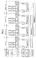
- FIG. 3 A more detailed illustration of the individual processes is shown in FIG. 3. It is shown here that an equidistance cycle comprises different cycles, but a control cycle in a control and / or regulating device 1 can take longer than an equidistance cycle, but this is not a problem, since then predetermined values are used for this control cycle, which result in a specific time t 0 - t n are stored and thus synchronized with each other.
- the synchronization signal determines the Equidistance clock for the slaves or components 3.
- the equidistance clock becomes the synchronization of the acquisition accordingly which uses input and output values.
- S / F means that Clock signal (i.e. a special broadcast telegram) illustrates which sets the equidistance clock.
- Clock signal i.e. a special broadcast telegram
- DPcyclic cyclical polling of the components is illustrated (i.e. read / write of input and output values).
- the Block Azykl illustrates acyclic DP communication.
- the pause block illustrates that waiting until the equidistance time has expired.
- the Master 1 shown here is a with a removable buffer. With the equidistance clock the Input and output buffers exchanged. Here is a buffer used by the application or CPU. A buffer is created by Bus system or components 3 used. Master 1 may only change the buffer if the enable signal (from the last equidistance cycle) exists. After this The release arrangement will be buffer change by master 1 reset again. It will change accordingly Approval request pending. This interaction of the buffers causes the input signals of all components to always be off a time t (x). So that becomes a Ensuring consistency.
- the actual control task is in the CPU shown carried out and the processing of the regulation takes place necessary program steps.
- the control task is started with the Equidistance clock called. After processing the various Program steps for controlling or regulating are carried out from this control task an enable signal to master 1. The master is now ready for a buffer change.
- control cycles the duration of a complete control cycle from the input (time t 0 -k) to the control with these input values and the output of the control results (time t 3 + k) is shown schematically.
Abstract
Description
Die Erfindung betrifft ein Verfahren und ein Steuer- und/oder Regelungssystem zum Steuern und/oder Regeln von verschiedenen Einrichtungen wie Antriebe, Stelltriebe, Sensoren etc., die über ein Feldbussystem an eine gemeinsame Steuer- und/oder Regelungsvorrichtung angeschlossen sind. Derartige Systeme sind in automatisierten Be- und Verarbeitungsanlagen zur Steuerung und/oder Regelung der für die jeweiligen Produktions- oder Arbeitsabläufe notwendigen einzelnen Betriebseinrichtungen notwendig. Insbesondere sind Automatisierungssysteme oder automatisch arbeitende Anlagen mit derartigen Steuer- bzw. Regelungssystemen ausgestattet.The invention relates to a method and a control and / or Control system for controlling and / or regulating various Devices such as drives, actuators, sensors etc., the via a fieldbus system to a common control and / or Control device are connected. Such systems are used in automated machining and processing systems Control and / or regulation of the for the respective production or work processes necessary for individual operating facilities necessary. Automation systems in particular or automatic systems with such Control systems equipped.
Allgemein ist in Automatisierungssystemen oder Fertigungsanlagen und dergleichen eine Tendenz zur Dezentralisierung und Verteilung festzustellen. In verteilten Systemen, Anlagen- und Maschinenkonfigurationen werden Eingänge wie Messwerte, Positionsangaben etc. und Ausgänge wie beispielsweise Stellsignale (u.a. Drehzahl, Position etc.) sowohl gesteuert und/oder auch geregelt über ein Feldbussystem verarbeitet. Genauer gesagt werden im Peripheriebereich ermittelte Eingangs- bzw. Istwerte von einer Steuer- bzw. Regelungsvorrichtung über ein Feldbussystem eingelesen, zentral in einer CPU des Steuerungs- bzw. Regelungssystems verarbeitet und über das Feldbussystem als Stellgröße der Ausgangsperipherie mitgeteilt. General is in automation systems or manufacturing plants and the like a tendency towards decentralization and determine distribution. In distributed systems, plant and machine configurations become inputs like Measured values, position information etc. and outputs such as Control signals (including speed, position, etc.) both controlled and / or regulated via a fieldbus system processed. More specifically, be in the peripheral area determined input or actual values from a control or Control device read in via a fieldbus system, centrally in a CPU of the control system processed and via the fieldbus system as the manipulated variable of Output periphery communicated.
Dabei werden häufig hohe dynamische Anforderungen über die gesamte Verarbeitungskette von der Ebene der Peripheriesignal, dem Feldbussystem bis zur Verarbeitungsinstanz, also dem Programm in der Steuer- bzw. Regelung gestellt.Often high dynamic requirements about the entire processing chain from the level of peripheral signal, the fieldbus system to the processing instance, that is the program in the tax or regulation.
Die technologische Applikation erfordert in echtzeitkritischen Anwendungen ein strikt einzuhaltendes Zeitraster der Verarbeitung über die gesamte Wirkungskette und eine vollsynchrone sowie jitterfreie Bearbeitung der Peripheriesignale sowohl beim Erfassen der Eingänge als auch beim Bereitstellen der Ausgänge. Die erreichbare Qualität und Güte der technologischen Applikation hängt dabei stark von den dynamischen Verhältnissen im Laufzeitsystem ab und ist im Wesentlichen von folgenden Faktoren mitbestimmt. So hat ein wesentlicher Anteil die Größe des strikt einzuhaltenden Verarbeitungszeitrasters, also des Äquidistanzzyklus. Auch die Höhe des maximal auftretenden Jitters des Äquidistanzzyklus ist von großer Bedeutung wie auch die Synchronität, d. h. die Gleichzeitigkeit der Bearbeitung der Peripheriesignale, also der Ein- und Ausgänge.The technological application requires real-time critical Applications a strict time frame of the Processing across the entire chain of effects and a fully synchronized and jitter-free processing of the peripheral signals both when recording the inputs and when providing them of the exits. The achievable quality and quality of the technological Application depends heavily on the dynamic Relationships in the runtime system and is essentially determined by the following factors. So has an essential one Share the size of the strictly adhered to processing time grid, so the equidistance cycle. Even the amount of maximum jitter that occurs in the equidistance cycle is from of great importance as well as synchronicity, d. H. the simultaneity the processing of the peripheral signals, i.e. the Inputs and outputs.
Bisherige, rein zentrale Automatisierungssysteme erreichten struktur- und implementierungsbedingt akzeptable Werte bei diesen zeitkritischen Parametern. Dezentrale Systeme hingegen verlieren hier durch weiträumigere Verteilung der beteiligten Komponenten und wegen der weitestgehenden Asynchronität diverser Bearbeitungszyklen in den Automatisierungskomponenten, also Steuerung, Feldbus, zentrale Peripherie etc., deutlich an Qualität, was beispielsweise in der Antriebs- und Regelungstechnik basierten Automatisierung von Produktionsabläufen bis hin zu numerischen Werkzeugmaschinen besonders kritisch im Hinblick auf die resultierende bzw. geforderte Regelungsgüte und Qualität ist. Die Asynchronität wird zusätzlich noch verstärkt durch den offenen Ansatz in der Feldtechnik, bei dem Geräte unterschiedlichster Komponentenlieferanten des Automatisierungssystems nicht synchronisiert betrieben werden können. Previous, purely central automation systems were achieved acceptable values due to structure and implementation these time-critical parameters. Decentralized systems, however, lose here due to the more extensive distribution of those involved Components and because of the greatest possible asynchrony various processing cycles in the automation components, control, fieldbus, central periphery etc., clearly in quality, for example in the drive and Control technology based automation of production processes up to numerical machine tools in particular critical with regard to the resulting or required Regulation quality and quality is. The asynchrony is additional reinforced by the open approach in the Field technology for devices from a wide variety of component suppliers of the automation system is not synchronized can be operated.
Bisher wurden zentrale, proprietäre Systeme eingesetzt, die mit hochspeziellen und firmenspezifischen Lösungen die erforderlichen Leistungsdaten für die Systeme wie Verarbeitungszyklen, Zyklenkonstanz etc. erreichen konnten. Dies wird heute zunehmend weniger von Anwendern akzeptiert, da sie die Vorteile der offenen Feldtechnik uneingeschränkt nutzen möchten. Diese Vorteile sind: Interoperabilität, Interchangeability. Hochspezielle Bussysteme, wie sie beispielsweise unter dem Markennamen SERCOS bekannt sind, werden wegen ihrer geringen Marktdurchdringung und ihrer Einschränkung auf Spezialsegmente nicht flächendeckend akzeptiert.So far, central, proprietary systems have been used the necessary with highly specialized and company-specific solutions Performance data for the systems such as processing cycles, Cycle consistency etc. could be achieved. this will less and less accepted by users today because they Want to fully benefit from the advantages of open field technology. These advantages are: interoperability, interchangeability. Highly specialized bus systems, such as those used for example are known under the brand name SERCOS because of their low market penetration and its restriction Special segments not accepted across the board.
Das der Erfindung zugrunde liegende technische Problem besteht darin, ein Steuer- und/oder Regelungssystem bereitzustellen, das trotz der Ankopplung der zu steuernden bzw. zu regelnden Komponenten über ein gemeinsames Feldbussystem auch hochdynamischen Anforderungen gerecht wird.The technical problem underlying the invention exists in providing a control and / or regulation system, this despite the coupling of the to be controlled or regulating components via a common fieldbus system too highly dynamic requirements.
Ein weiteres der Erfindung zugrunde liegende technische Problem besteht darin, ein hochdynamischen Anforderungen gerecht werdendes Verfahren bereitzustellen, mit dem über ein gemeinsames Feldbussystem an eine Steuer- und/oder Regelungsvorrichtung angeschlossene Komponenten gesteuert und/oder geregelt werden können.Another technical on which the invention is based Problem is a highly dynamic requirement to provide a fair procedure with which over a common fieldbus system to a control and / or regulating device connected components controlled and / or can be regulated.
Diese technischen Probleme werden durch ein Steuer- und/oder
Regelungssystem mit den Merkmalen des Anspruchs 1 bzw. durch
ein Verfahren mit den Merkmalen des Anspruchs 7 gelöst.These technical problems are caused by a tax and / or
Control system with the features of
Der Erfindung liegt der Gedanke zugrunde, die bisher frei laufenden Verarbeitungszyklen starr an den Zyklus des Feldbussystems zu koppeln, indem ein Takt zur Synchronisation vorgegeben wird. Insbesondere sollen die bisher freilaufenden Verarbeitungszyklen der gesamten Wirkungskette von den Einund Ausgängen über proprietäre Rückwandbussysteme der dezentralen, an dem Feldbus angeschlossenen Komponenten wie Peripheriestation oder Feldgeräte (Messeinrichtungen, Antriebe, Sensoren, Werkzeuge etc. ) bis über den Feldbus selbst hin zur Verarbeitungsebene, d.h. der Programmbearbeitung in der Steuer- bzw. Regelungsvorrichtung starr gekoppelt werden. Damit ist es vorzugsweise möglich, die Eingangs- bzw. Messwerterfassung in diesem durch das Synchronisationssignal vorgegebenen Äquidistanzraster synchron zu erfassen, d.h. diese Werte zu genau festgelegten, in einem vorgegebenen zeitlichen Abstand zueinander liegenden Zeitpunkten zu erfassen, wodurch alle an dem Feldbussystem angeschlossenen Komponenten zeitlich aufeinander abstimmbar sind, insbesondere die einzelnen Werte (Ein- und Ausgänge) zu vorgegebenen Zeitpunkten abrufbar sind. Es ist damit erstmals möglich, auch die aus den Eingangswerten errechneten Stellgrößen zu bestimmten Zeitpunkten auszugeben bzw. diesen Werten einen bestimmten Zeitpunkt zuzuordnen, wodurch die einzelnen, am Feldbussystem angeschlossenen Komponenten gleichzeitig mit den jeweiligen Werten versorgbar sind.The invention is based on the idea that has so far been free current processing cycles rigidly to the cycle of the fieldbus system to couple by a clock for synchronization is specified. In particular, the previously free-running Processing cycles of the entire chain of effects from the single and Exits via proprietary backplane bus systems of the decentralized, components connected to the fieldbus such as Peripheral station or field devices (measuring devices, drives, Sensors, tools etc.) up to the fieldbus itself to the processing level, i.e. program processing rigid in the control device be coupled. So that it is preferably possible to Input or measured value acquisition in this by the synchronization signal predetermined equidistance grid synchronously to grasp, i.e. these values to be set precisely in one predetermined time interval from each other to detect, whereby all connected to the fieldbus system Components can be coordinated with one another , especially the individual values (inputs and outputs) predefined times are available. It is the first time possible, also the manipulated variables calculated from the input values to output at certain times or these values to assign a specific point in time, whereby the individual, Components connected to the fieldbus system at the same time can be supplied with the respective values.
Durch diese Maßnahmen erfolgt eine auch hochdynamischen Verhältnissen gerecht werdende genaue Steuer- bzw. Regelung einer mehrere über das Feldbussystem angekoppelte Komponenten umfassenden Anlage wie beispielsweise eine Durchlaufbearbeitungsanlage oder dergleichen.These measures also result in highly dynamic conditions accurate control or regulation one of several components coupled via the fieldbus system comprehensive system such as a continuous processing system or similar.
Es erfolgt ferner vorzugsweise eine starre und synchrone Kopplung des Feldbuszyklus an die Verarbeitungstasks in der Steuer- bzw. Regelung. Insbesondere ist ein synchrones Einfrieren der Eingänge und eine Übertragung der Eingänge in Wechselpuffer möglich. Außerdem ist ein synchroner Start der Verarbeitungstasks mit Pufferwechsel und konsistenten Nutzdatenabbild für die Verarbeitungstasks durchführbar.There is also preferably a rigid and synchronous Coupling the fieldbus cycle to the processing tasks in the Tax or regulation. In particular, synchronous freezing is of the inputs and a transfer of the inputs in Exchange buffer possible. In addition, a synchronous start is the Processing tasks with a buffer change and consistent user data image feasible for the processing tasks.
Vorzugsweise ist ein Wechselpuffer vorhanden, der die Verarbeitungszyklen in der Feldbusebene und der Programmbearbeitung in der Steuer bzw. Regelung voneinander trennt. Durch Puffertausch und Synchronisationsimpulse erfolgt ein synchrones Ausgeben der Ausgänge zum Prozess. Die Stellgrößen, also die Ausgänge, werden im nächsten oder weiteren Zyklus u.U. auch asynchron ausgegeben.A change buffer is preferably provided which contains the processing cycles at the fieldbus level and program processing separates from each other in the control or regulation. By exchanging buffers and synchronization pulses synchronous output of the outputs to the process. The manipulated variables, so the exits will be in the next or further Cycle may also output asynchronously.
Zwischen dem Verarbeitungstask und dem Äquidistanzzyklus ist also ein enger und strikter Zeitbezug vorgegeben. Sollte aufgrund von Fehlern in Übertragungssystemen der Äquidistanzzyklus sporadisch oder permanent verfehlt werden oder ein Verarbeitungstask langsamer sein als der Äquidistanzzyklus, so ergeben sich an der Aufrufschnittstelle des Verarbeitungstasks insbesondere folgende Besonderheiten. Es wird kommunikationsseitig, z.B. bei Busstörungen im Feldbussystem mit hoher Wiederholungsrate von Telegrammen, die Äquidistanzzeit überschritten, so erhält der Verarbeitungstask in seiner Startfunktion die entsprechende Signalisierung inklusive des Abweichungswertes vom Äquidistanzzyklus. Die Applikation in der Verarbeitungstask kann dann ein entsprechendes Fehlermanagement durchführen.Between the processing task and the equidistance cycle So a tight and strict time reference is given. Should be due errors in transmission systems the equidistance cycle be missed sporadically or permanently or a Processing task be slower than the equidistance cycle, this results in the call interface of the processing task in particular the following special features. It becomes communication side, e.g. with bus faults in the fieldbus system high repetition rate of telegrams, the equidistance time exceeded, the processing task receives in its Start function the corresponding signaling including the Deviation value from the equidistance cycle. The application in the processing task can then perform appropriate error management carry out.
Verlängert sich der Bearbeitungstask in der Steuerung über den Äquidistanzzyklus hinaus, z.B. wegen extremer Interrupt-Last, greift das Wechselprinzip dahingehend, dass mit alten, im Puffer befindlichen Werten, weitergearbeitet wird, bis die neue Task neue Werte zur Verfügung stellt.The processing task in the control is extended via beyond the equidistance cycle, e.g. due to extreme interrupt load, the change principle applies that with old, values in the buffer are continued until the new task provides new values.
Durch diese neuartige Ausgestaltung eines Steuer- und Regelungssystems profitieren hier insbesondere antriebsbasierte Systeme in der Produktionsautomatisierung und im Werkzeugmaschinenbau. Es können neben Einachsaufgaben auch verkoppelte Achsen realisiert werden.This new design of a tax and Control systems benefit in particular from drive-based systems Systems in production automation and in Machine tool industry. In addition to single-axis tasks, it can also coupled axes can be realized.
Falls ein Regelungstask länger dauert als der Zeitabstand zwischen zwei Zeitpunkten, die durch das Synchronisationssignal vorgegeben sind, das heißt, einem Äquidistanzzyklus, so ist dies kein Problem, da für die Verarbeitung immer bekannt ist, wann welche Werte generiert und abgespeichert wurden. So kann zu bestimmten Zeitpunkten immer auf die entsprechend passend synchronisierten Werte (Ein- und Ausgänge) zurückgegriffen werden.If a control task lasts longer than the interval between two times by the synchronization signal are specified, that is, an equidistance cycle, so this is not a problem as it is always for processing it is known when which values are generated and saved were. So at certain times you can always refer to the correspondingly synchronized values (inputs and outputs) be resorted to.
Im Folgenden sind zum besseren Verständnis und zur Erläuterung mehrere Ausführungsbeispiele der Erfindung unter Bezugnahme auf die beigefügten Zeichnungen näher beschrieben. Es zeigt:
- Fig. 1
- eine schematische Darstellung eines Steuer- und/oder Regelungssystems gemäß der Erfindung,
- Fig. 2
- eine schematisierte Darstellung der über das gemeinsame Feldbussystem erfolgenden Abläufe über die Zeit und
- Fig. 3
- eine schematisierte Darstellung ähnlich der Fig. 2 mit verschiedenen Ebenen.
- Fig. 1
- 1 shows a schematic representation of a control and / or regulation system according to the invention,
- Fig. 2
- a schematic representation of the processes taking place over the common fieldbus system over time and
- Fig. 3
- a schematic representation similar to FIG. 2 with different levels.
Der grundsätzliche Aufbau eines Steuerungs- und/oder Regelungssystems
gemäß der Erfindung ist aus der Fig. 1 ersichtlich.
Hier ist eine Steuer- und/oder Regelungsvorrichtung 1
über ein Profibussystem 2 mit verschiedenen Komponenten 3 wie
beispielsweise Messwertaufnehmer, Sensoren, Antriebe, Werkzeuge,
Stellglieder etc. verbunden. Im vorliegenden Fall ist
das Feldbussystem 2 ein Profibus DP. In der Steuer- und/oder
Regelungsvorrichtung 1 ist erfindungsgemäß eine Synchronisationssignal-Generierungseinrichtung
4 vorhanden, die ein
Synchronisationssignal generiert, mit dem die Zyklen des
Feldbussystems 2 mit den Verarbeitungstasks in der Steuerund/oder
Regelungsvorrichtung 1 gekoppelt werden. Hierzu wird
im Folgenden noch näher eingegangen. Im Hinblick auf die Ausgestaltung
des Feldbussystems wird auf die weitverbreitete
Literatur, insbesondere der zum Profibus DP verwiesen. Diese
Literatur wird hier ausdrücklich durch Bezugnahme mit aufgenommen.The basic structure of a control and / or regulation system
according to the invention can be seen from FIG. 1.
Here is a control and / or regulating
In üblicher Weise werden durch die Einrichtungen 3, Feldgeräte
oder Komponenten Messwerte oder Positionsangaben über
das Feldbussystem 2 an die Steuerungs- und/oder Regelungsvorrichtung
1 übermittelt. Dort wird eine Verarbeitung durchgeführt,
d.h. ein Programmablauf erfolgt mit den durch die
Komponenten 3 gegebenen Eingangssignalen, d.h. Eingangswerten.
Die errechneten Ausgangswerte, Stellgrößen bzw.
Stellwerte werden wiederum über das Profibussystem DP 2 an
die Komponenten 3 übermittelt, die dann entsprechend verfahren
oder gesteuert bzw. geregelt werden. Damit ist eine automatische
Steuer- und/oder Regelung einer mehrere Motoren,
Werkzeuge etc. umfassenden Anlage wie beispielsweise eine
Durchlaufbearbeitungsanlage regelbar.In the usual way,
In der Fig. 2 ist nun die erfindungsgemäße Triggerung der
Abläufe besser ersichtlich. Hier ist über den Zeitstrahl t
die regelmäßige periodische Signalgenerierung mit Äqui_1,
Äqui_2, Äqui_3 und Äqui_4 bzw. t1 - t4 veranschaulicht. Zu
dem Zeitpunkt t1 werden Istwerte im Verfahrensschritt 5 von
einer Komponente 3 zum Feldbussystem 2 übertragen. Im Verfahrensschritt
6 erfolgt dann der Transport dieser Werte zu
der Steuer- und oder Regelungsvorrichtung 1. Dieser Transport
liegt im vorliegenden Fall innerhalb eines Äquidistanzzyklus,
d.h. zwischen den Zeitpunkten t1 und t2. Zum Zeitpunkt t2
erfolgt dann in einem Verarbeitungstask die Regelung gemäß
Verfahrensschritt 7, die Ausgangssignale, d.h. die Stellwerte,
werden dann zum Zeitpunkt t3 an das Feldbussystem 2
übertragen. Zwischen den Zeitpunkten t3 und t4 erfolgt dann
in einem weiteren Verfahrensschritt 8 der Transport der Ausgangswerte
zu den einzelnen Komponenten. Zum Zeitpunkt t4
erfolgt schließlich die Übertragung dieser Werte in einem
weiteren Verfahrensschritt 9. Die Zeitabstände zwischen den
einzelnen Zeitpunkten t1 - t4 sind immer gleich und durch das
Synchronisationssignal vorgegeben.2, the triggering of the processes according to the invention can now be seen better. The periodic signal generation with Equi_1, Equi_2, Equi_3 and Equi_4 or t 1 - t 4 is illustrated here via the time line t. At time t 1 , actual values are transferred from
Eine genauere Darstellung der einzelnen Abläufe ist in der
Fig. 3 gezeigt. Hier ist dargestellt, dass ein Äquidistanzzyklus
verschiedene Zyklen umfasst, ein Regelungszyklus in
einer Steuer- und/oder Regelungseinrichtung 1 kann aber
länger als ein Äquidistanzzyklus dauern, das ist jedoch kein
Problem, da dann für diesen Regelungszyklus auf vorgegebene
Werte zurückgegriffen wird, die zu einem bestimmten Zeitpunkt
t0 - tn abgespeichert und damit zueinander synchronisiert
sind.A more detailed illustration of the individual processes is shown in FIG. 3. It is shown here that an equidistance cycle comprises different cycles, but a control cycle in a control and / or regulating
Wie in der Fig. 3 schematisch dargestellt und wie es bereits
zuvor erläutert wurde, werden allgemein zu Zeiten t(x)- k (k
= Konstante die Eingangssignale oder Werte (erfasste Istwerte)
ausgegeben und zu Zeiten t(x)+ k (k = Konstante werden
die Ausgangswerte bzw. Ausgangssignale (Sollwerte) ausgegeben.
Mit Slaves sind hier die Komponenten 3 gemeint. In
der Fig. 3 ist in einfachster Weise verdeutlicht, wie das
zyklische Lesen bzw. Schreiben der Ein- und Ausgangssignale
von den einzelnen Komponenten über die Zeitachse, d.h. pro
Äquidistanzzyklus erfolgt. Es wird also pro Äquidistanzzyklus
von jeder Komponente 3 einmal ein von der Steuer- und/oder
Regelungsvorrichtung 1 (setzt sich in der Fig. 3 aus Master
und CPU zusammen) errechneter Sollwert gelesen und ein erfasster
Istwert geschrieben, der dann über den Feldbus 2 an
die Steuer- und/oder Regelungsvorrichtung übermittelt wird.
Das Synchronisationssignal gemäß der Erfindung bestimmt den
Äquidistanztakt für die Slaves bzw. Komponenten 3. Der Äquidistanztakt
wird entsprechend zur Synchronisation der Erfassung
der Ein- und Ausgabewerte benutzt.As shown schematically in Fig. 3 and as it already does
previously explained, generally at times t (x) - k (k
= Constant the input signals or values (recorded actual values)
are output and at times t (x) + k (k = constant
the output values or output signals (setpoints) are output.
Bei der in der Fig. 3 gezeigten Darstellung ist mit S/F das Taktsignal (d.h. ein spezielles Broadcast-Telegramm) veranschaulicht, das den Äquidistanztakt vorgibt. Mit DPzyklisch ist das zyklische Abfragen der Komponenten veranschaulicht (d.h. read/write von Ein- und Ausgabewerten). Der Block Azykl veranschaulicht eine azyklische DP-Kommunikation. Mit dem Block Pause wird veranschaulicht, dass abgewartet wird, bis die Äquidistanzzeit abgelaufen ist.In the illustration shown in FIG. 3, S / F means that Clock signal (i.e. a special broadcast telegram) illustrates which sets the equidistance clock. With DPcyclic cyclical polling of the components is illustrated (i.e. read / write of input and output values). The Block Azykl illustrates acyclic DP communication. The pause block illustrates that waiting until the equidistance time has expired.
Bei dem hier gezeigten Master 1 handelt es sich um einen mit
einem Wechselpuffer. Mit dem Äquidistanztakt werden die
Eingabe- und Ausgabepuffer getauscht. Hier wird ein Puffer
von der Applikation bzw. CPU benutzt. Ein Puffer wird vom
Bussystem bzw. den Komponenten 3 benutzt. Der Master 1 darf
den Pufferwechsel nur durchführen, wenn das Freigabesignal
(aus dem letzten Äquidistanzzyklus) vorhanden ist. Nach dem
Pufferwechsel wird die Freigabeanordnung durch den Master 1
wieder zurückgesetzt. Es wird entsprechend auf eine neue
Freigabeanforderung gewartet. Dieses Zusammenspiel der Puffer
bewirkt, dass die Eingabesignale aller Komponenten immer aus
einem Zeitpunkt t(x) stammen. Damit wird eine
Konsistenzsicherung bewirkt.The
Der eigentliche Regelungstask wird in der dargestellten CPU
durchgeführt und es erfolgt die Abarbeitung der zur Regelung
notwendigen Programmschritte. Der Regelungstask wird mit dem
Äquidistanztakt aufgerufen. Nach Abarbeitung der verschiedenen
Programmschritte zum Steuern bzw. zur Regelung erfolgt
aus diesem Regelungstask ein Freigabesignal an den Master 1.
Damit ist der Master fertig für einen Pufferwechsel.The actual control task is in the CPU shown
carried out and the processing of the regulation takes place
necessary program steps. The control task is started with the
Equidistance clock called. After processing the various
Program steps for controlling or regulating are carried out
from this control task an enable signal to
In dem letzten Block, der mit "Regelzyklen" gekennzeichnet ist, ist schematisch die Dauer eines kompletten Regelungszyklus von der Eingabe (Zeitpunkt t0 - k) über die Regelung mit diesen Eingabewerten bis zur Ausgabe der Regelungsergebnisse (Zeitpunkt t3 + k) dargestellt.In the last block, which is labeled "control cycles", the duration of a complete control cycle from the input (time t 0 -k) to the control with these input values and the output of the control results (time t 3 + k) is shown schematically.
Claims (14)
Applications Claiming Priority (2)
| Application Number | Priority Date | Filing Date | Title |
|---|---|---|---|
| DE10120558A DE10120558A1 (en) | 2001-04-26 | 2001-04-26 | Method and device for controlling and / or regulating devices coupled to a control and / or regulating device via a common fieldbus system |
| DE10120558 | 2001-04-26 |
Publications (3)
| Publication Number | Publication Date |
|---|---|
| EP1253494A2 true EP1253494A2 (en) | 2002-10-30 |
| EP1253494A3 EP1253494A3 (en) | 2007-05-30 |
| EP1253494B1 EP1253494B1 (en) | 2009-09-30 |
Family
ID=7682874
Family Applications (1)
| Application Number | Title | Priority Date | Filing Date |
|---|---|---|---|
| EP02009582A Revoked EP1253494B1 (en) | 2001-04-26 | 2002-04-26 | Control device with field bus |
Country Status (3)
| Country | Link |
|---|---|
| EP (1) | EP1253494B1 (en) |
| AT (1) | ATE444504T1 (en) |
| DE (2) | DE10120558A1 (en) |
Cited By (10)
| Publication number | Priority date | Publication date | Assignee | Title |
|---|---|---|---|---|
| EP1450265A1 (en) * | 2003-02-10 | 2004-08-25 | Omron Corporation | Inverter |
| EP1688809A1 (en) * | 2004-08-17 | 2006-08-09 | Obshschestvo S Ogranichennoy Otveetstvennostiuy "Promishlennaya Gruppa" Finprom - Resurs" | Device for controlling a system of objects through a power line and an adapter therefor |
| EP2169487A1 (en) * | 2008-09-29 | 2010-03-31 | Rockwell Automation Technologies, Inc. | Industrial controller with coordination of network transmissions using global clock |
| WO2014161855A1 (en) * | 2013-04-03 | 2014-10-09 | Phoenix Contact Gmbh & Co.Kg | Method and control device for the output of data on a local bus |
| JP2015049902A (en) * | 2013-08-30 | 2015-03-16 | ドクトル・ヨハネス・ハイデンハイン・ゲゼルシヤフト・ミツト・ベシユレンクテル・ハフツングDr. Johannes Heidenhain Gesellschaft Mitbeschrankter Haftung | Method and facility for synchronization of one control device with at least one peripheral device |
| US9274993B2 (en) | 2012-03-23 | 2016-03-01 | Siemens Aktiengesellschaft | Interface device and method for consistently exchanging data |
| US9436212B2 (en) | 2012-09-17 | 2016-09-06 | Wago Verwaltungsgesellschaft Mbh | Data bus part and method for synchronizing data bus parts |
| EP3082118A1 (en) * | 2015-04-14 | 2016-10-19 | Dräger Safety AG & Co. KGaA | Method for transmitting data between measuring devices and a data processing system in a measurement data recording device |
| EP3223093A1 (en) * | 2016-03-24 | 2017-09-27 | Omron Corporation | Optical measurement device |
| EP2730988A3 (en) * | 2012-11-08 | 2017-10-25 | General Electric Company | Systems and methods for segment synchronization |
Families Citing this family (3)
| Publication number | Priority date | Publication date | Assignee | Title |
|---|---|---|---|---|
| DE10338514B4 (en) * | 2003-08-21 | 2013-09-19 | Lenze Automation Gmbh | Drive system with decentralized intelligence |
| DE102009037156A1 (en) | 2009-08-04 | 2011-02-17 | Lenze Automation Gmbh | Method for the synchronous recording and recording of process and / or status data and automation system |
| DE102018111452A1 (en) * | 2018-05-14 | 2019-11-14 | Carl Zeiss Ag | Control unit for real-time systems |
Family Cites Families (2)
| Publication number | Priority date | Publication date | Assignee | Title |
|---|---|---|---|---|
| DE19917354B4 (en) * | 1999-04-16 | 2005-12-22 | Siemens Ag | Synchronization method for a main unit and at least one subsidiary unit with internal timers to be synchronized with each other, communication system corresponding thereto, and main unit and slave unit of such a communication system |
| DE19943724A1 (en) * | 1999-09-04 | 2001-03-15 | Imc Messysteme Gmbh | Arrangement for synchronizing clock generator of several slave devices connected to field bus e.g. for industrial systems in communication devices |
-
2001
- 2001-04-26 DE DE10120558A patent/DE10120558A1/en not_active Withdrawn
-
2002
- 2002-04-26 AT AT02009582T patent/ATE444504T1/en not_active IP Right Cessation
- 2002-04-26 EP EP02009582A patent/EP1253494B1/en not_active Revoked
- 2002-04-26 DE DE50213877T patent/DE50213877D1/en not_active Expired - Lifetime
Non-Patent Citations (1)
| Title |
|---|
| None |
Cited By (20)
| Publication number | Priority date | Publication date | Assignee | Title |
|---|---|---|---|---|
| EP1450265A1 (en) * | 2003-02-10 | 2004-08-25 | Omron Corporation | Inverter |
| US7026784B2 (en) | 2003-02-10 | 2006-04-11 | Omron Corporation | Inverter |
| US7119514B2 (en) | 2003-02-10 | 2006-10-10 | Omron Corporation | Inverter |
| EP1688809A1 (en) * | 2004-08-17 | 2006-08-09 | Obshschestvo S Ogranichennoy Otveetstvennostiuy "Promishlennaya Gruppa" Finprom - Resurs" | Device for controlling a system of objects through a power line and an adapter therefor |
| EP1688809A4 (en) * | 2004-08-17 | 2007-01-03 | Obshschestvo S Ogranichennoy O | Device for controlling a system of objects through a power line and an adapter therefor |
| EP2169487A1 (en) * | 2008-09-29 | 2010-03-31 | Rockwell Automation Technologies, Inc. | Industrial controller with coordination of network transmissions using global clock |
| US7930041B2 (en) | 2008-09-29 | 2011-04-19 | Rockwell Automation Technologies, Inc. | Industrial controller with coordination of network transmissions using global clock |
| US9274993B2 (en) | 2012-03-23 | 2016-03-01 | Siemens Aktiengesellschaft | Interface device and method for consistently exchanging data |
| US9436212B2 (en) | 2012-09-17 | 2016-09-06 | Wago Verwaltungsgesellschaft Mbh | Data bus part and method for synchronizing data bus parts |
| EP2730988A3 (en) * | 2012-11-08 | 2017-10-25 | General Electric Company | Systems and methods for segment synchronization |
| WO2014161855A1 (en) * | 2013-04-03 | 2014-10-09 | Phoenix Contact Gmbh & Co.Kg | Method and control device for the output of data on a local bus |
| JP2015049902A (en) * | 2013-08-30 | 2015-03-16 | ドクトル・ヨハネス・ハイデンハイン・ゲゼルシヤフト・ミツト・ベシユレンクテル・ハフツングDr. Johannes Heidenhain Gesellschaft Mitbeschrankter Haftung | Method and facility for synchronization of one control device with at least one peripheral device |
| EP2843486A3 (en) * | 2013-08-30 | 2015-04-01 | Dr. JOHANNES HEIDENHAIN GmbH | Method and apparatus for synchronising a control unit and at least one associated peripheral unit |
| US9703749B2 (en) | 2013-08-30 | 2017-07-11 | Johannes Heidenhain Gmbh | Method and device for synchronizing a control unit and at least one assigned peripheral unit |
| EP3082118A1 (en) * | 2015-04-14 | 2016-10-19 | Dräger Safety AG & Co. KGaA | Method for transmitting data between measuring devices and a data processing system in a measurement data recording device |
| CN106056888A (en) * | 2015-04-14 | 2016-10-26 | 德尔格安全股份两合公司 | Method for data transmission between measuring apparatuses and data processing device in measured data recording system |
| US9693121B2 (en) | 2015-04-14 | 2017-06-27 | Dräger Safety AG & Co. KGaA | Method for data transmission between measuring apparatuses and a data processing device in a measured data recording system |
| CN106056888B (en) * | 2015-04-14 | 2019-05-03 | 德尔格安全股份两合公司 | Method for carrying out data transmission between measuring device and data processing equipment |
| EP3223093A1 (en) * | 2016-03-24 | 2017-09-27 | Omron Corporation | Optical measurement device |
| US10254108B2 (en) | 2016-03-24 | 2019-04-09 | Omron Corporation | Optical measurement device |
Also Published As
| Publication number | Publication date |
|---|---|
| EP1253494A3 (en) | 2007-05-30 |
| DE10120558A1 (en) | 2002-10-31 |
| EP1253494B1 (en) | 2009-09-30 |
| ATE444504T1 (en) | 2009-10-15 |
| DE50213877D1 (en) | 2009-11-12 |
Similar Documents
| Publication | Publication Date | Title |
|---|---|---|
| EP2621193B1 (en) | Device for transmitting sensor data | |
| EP1657619B1 (en) | Method for time synchronisation in a cyclically working communication system | |
| WO2003028258A1 (en) | Method for synchronising nodes of a communications system | |
| EP1253494B1 (en) | Control device with field bus | |
| DE19645735A1 (en) | Numerical control system using a personal computer and method for controlling the same | |
| DE19813203A1 (en) | Servo control method for serial communication process | |
| DE3236302A1 (en) | PROGRAMMABLE CONTROL | |
| DE102005011285A1 (en) | Apparatus and method for coordinate measurement | |
| DE102017208831A1 (en) | Processing of process data | |
| EP1368728A2 (en) | Synchronous, clocked communication system with a relative time clock and method for establishing such a system | |
| EP2544388B1 (en) | Method for cycle and time unit synchronisation in an automation network | |
| EP1064589B1 (en) | Method for synchronising a local time base on a central time base and device for implementing said method with preferred applications | |
| DE10144788A1 (en) | Process data recording method e.g. for robot, involves storing process data in data buffer memory having first-in-first out characteristic | |
| EP1692579B1 (en) | Method and device for operating interacting different units | |
| DE60027929T2 (en) | NUMERICAL CONTROL SYSTEM AND METHOD FOR FIXING TRANSMISSION COTS IN A NUMERICAL CONTROL SYSTEM | |
| EP3032429B1 (en) | Method and device for reading a serial data stream | |
| DE102010064123B3 (en) | Method for controlling peripheral devices of an isochronous bus system and third party peripheral devices of a third-party bus system and associated bus converter | |
| DE19815647A1 (en) | Method for synchronizing a local to a central time base, and device for carrying out the method with preferred uses | |
| DE10229110A1 (en) | Method for synchronizing nodes of a communication system | |
| EP1184755B1 (en) | Method for operating a peripheral unit comprising one main group and at least one input group | |
| EP2746892B1 (en) | Automated system and method for synchronising an automated system | |
| DE3123379C2 (en) | ||
| EP4179425A1 (en) | Method for transferring a software application from a first to a second data processing device | |
| DE10237097B4 (en) | Correction of signal propagation times in distributed communication systems | |
| DE19504291C2 (en) | Method of operating a network |
Legal Events
| Date | Code | Title | Description |
|---|---|---|---|
| PUAI | Public reference made under article 153(3) epc to a published international application that has entered the european phase |
Free format text: ORIGINAL CODE: 0009012 |
|
| AK | Designated contracting states |
Kind code of ref document: A2 Designated state(s): AT BE CH CY DE DK ES FI FR GB GR IE IT LI LU MC NL PT SE TR |
|
| AX | Request for extension of the european patent |
Free format text: AL;LT;LV;MK;RO;SI |
|
| PUAL | Search report despatched |
Free format text: ORIGINAL CODE: 0009013 |
|
| AK | Designated contracting states |
Kind code of ref document: A3 Designated state(s): AT BE CH CY DE DK ES FI FR GB GR IE IT LI LU MC NL PT SE TR |
|
| AX | Request for extension of the european patent |
Extension state: AL LT LV MK RO SI |
|
| 17P | Request for examination filed |
Effective date: 20070709 |
|
| 17Q | First examination report despatched |
Effective date: 20070903 |
|
| AKX | Designation fees paid |
Designated state(s): AT CH DE ES FR GB LI |
|
| APBK | Appeal reference recorded |
Free format text: ORIGINAL CODE: EPIDOSNREFNE |
|
| APBN | Date of receipt of notice of appeal recorded |
Free format text: ORIGINAL CODE: EPIDOSNNOA2E |
|
| APBV | Interlocutory revision of appeal recorded |
Free format text: ORIGINAL CODE: EPIDOSNIRAPE |
|
| GRAP | Despatch of communication of intention to grant a patent |
Free format text: ORIGINAL CODE: EPIDOSNIGR1 |
|
| GRAS | Grant fee paid |
Free format text: ORIGINAL CODE: EPIDOSNIGR3 |
|
| GRAA | (expected) grant |
Free format text: ORIGINAL CODE: 0009210 |
|
| AK | Designated contracting states |
Kind code of ref document: B1 Designated state(s): AT CH DE ES FR GB LI |
|
| REG | Reference to a national code |
Ref country code: CH Ref legal event code: EP Ref country code: GB Ref legal event code: FG4D Free format text: NOT ENGLISH |
|
| REF | Corresponds to: |
Ref document number: 50213877 Country of ref document: DE Date of ref document: 20091112 Kind code of ref document: P |
|
| PG25 | Lapsed in a contracting state [announced via postgrant information from national office to epo] |
Ref country code: ES Free format text: LAPSE BECAUSE OF FAILURE TO SUBMIT A TRANSLATION OF THE DESCRIPTION OR TO PAY THE FEE WITHIN THE PRESCRIBED TIME-LIMIT Effective date: 20100110 |
|
| PLBI | Opposition filed |
Free format text: ORIGINAL CODE: 0009260 |
|
| PLAX | Notice of opposition and request to file observation + time limit sent |
Free format text: ORIGINAL CODE: EPIDOSNOBS2 |
|
| 26 | Opposition filed |
Opponent name: WAGO KONTAKTTECHNIK GMBH & CO. KG Effective date: 20100623 |
|
| REG | Reference to a national code |
Ref country code: CH Ref legal event code: PL |
|
| PLAF | Information modified related to communication of a notice of opposition and request to file observations + time limit |
Free format text: ORIGINAL CODE: EPIDOSCOBS2 |
|
| PLBB | Reply of patent proprietor to notice(s) of opposition received |
Free format text: ORIGINAL CODE: EPIDOSNOBS3 |
|
| PG25 | Lapsed in a contracting state [announced via postgrant information from national office to epo] |
Ref country code: LI Free format text: LAPSE BECAUSE OF NON-PAYMENT OF DUE FEES Effective date: 20100430 Ref country code: CH Free format text: LAPSE BECAUSE OF NON-PAYMENT OF DUE FEES Effective date: 20100430 |
|
| PG25 | Lapsed in a contracting state [announced via postgrant information from national office to epo] |
Ref country code: AT Free format text: LAPSE BECAUSE OF NON-PAYMENT OF DUE FEES Effective date: 20100426 |
|
| RDAF | Communication despatched that patent is revoked |
Free format text: ORIGINAL CODE: EPIDOSNREV1 |
|
| APBM | Appeal reference recorded |
Free format text: ORIGINAL CODE: EPIDOSNREFNO |
|
| APBP | Date of receipt of notice of appeal recorded |
Free format text: ORIGINAL CODE: EPIDOSNNOA2O |
|
| APAH | Appeal reference modified |
Free format text: ORIGINAL CODE: EPIDOSCREFNO |
|
| APBQ | Date of receipt of statement of grounds of appeal recorded |
Free format text: ORIGINAL CODE: EPIDOSNNOA3O |
|
| RAP2 | Party data changed (patent owner data changed or rights of a patent transferred) |
Owner name: SIEMENS AKTIENGESELLSCHAFT |
|
| PLAB | Opposition data, opponent's data or that of the opponent's representative modified |
Free format text: ORIGINAL CODE: 0009299OPPO |
|
| R26 | Opposition filed (corrected) |
Opponent name: WAGO KONTAKTTECHNIK GMBH & CO. KG Effective date: 20100623 |
|
| RAP2 | Party data changed (patent owner data changed or rights of a patent transferred) |
Owner name: SIEMENS AKTIENGESELLSCHAFT |
|
| PGFP | Annual fee paid to national office [announced via postgrant information from national office to epo] |
Ref country code: DE Payment date: 20150619 Year of fee payment: 14 |
|
| REG | Reference to a national code |
Ref country code: FR Ref legal event code: PLFP Year of fee payment: 15 |
|
| REG | Reference to a national code |
Ref country code: DE Ref legal event code: R103 Ref document number: 50213877 Country of ref document: DE Ref country code: DE Ref legal event code: R064 Ref document number: 50213877 Country of ref document: DE |
|
| APBU | Appeal procedure closed |
Free format text: ORIGINAL CODE: EPIDOSNNOA9O |
|
| RDAG | Patent revoked |
Free format text: ORIGINAL CODE: 0009271 |
|
| STAA | Information on the status of an ep patent application or granted ep patent |
Free format text: STATUS: PATENT REVOKED |
|
| 27W | Patent revoked |
Effective date: 20160613 |
|
| GBPR | Gb: patent revoked under art. 102 of the ep convention designating the uk as contracting state |
Effective date: 20160613 |
|
| PGFP | Annual fee paid to national office [announced via postgrant information from national office to epo] |
Ref country code: GB Payment date: 20160411 Year of fee payment: 15 |
|
| PGFP | Annual fee paid to national office [announced via postgrant information from national office to epo] |
Ref country code: FR Payment date: 20160429 Year of fee payment: 15 |
|
| REG | Reference to a national code |
Ref country code: AT Ref legal event code: MA03 Ref document number: 444504 Country of ref document: AT Kind code of ref document: T Effective date: 20160613 |