EP1254803A2 - Reduction of slip during regenerative braking - Google Patents
Reduction of slip during regenerative braking Download PDFInfo
- Publication number
- EP1254803A2 EP1254803A2 EP02252868A EP02252868A EP1254803A2 EP 1254803 A2 EP1254803 A2 EP 1254803A2 EP 02252868 A EP02252868 A EP 02252868A EP 02252868 A EP02252868 A EP 02252868A EP 1254803 A2 EP1254803 A2 EP 1254803A2
- Authority
- EP
- European Patent Office
- Prior art keywords
- axle
- braking
- wheeled axle
- wheeled
- vehicle
- Prior art date
- Legal status (The legal status is an assumption and is not a legal conclusion. Google has not performed a legal analysis and makes no representation as to the accuracy of the status listed.)
- Granted
Links
Images

Classifications
-
- B—PERFORMING OPERATIONS; TRANSPORTING
- B60—VEHICLES IN GENERAL
- B60L—PROPULSION OF ELECTRICALLY-PROPELLED VEHICLES; SUPPLYING ELECTRIC POWER FOR AUXILIARY EQUIPMENT OF ELECTRICALLY-PROPELLED VEHICLES; ELECTRODYNAMIC BRAKE SYSTEMS FOR VEHICLES IN GENERAL; MAGNETIC SUSPENSION OR LEVITATION FOR VEHICLES; MONITORING OPERATING VARIABLES OF ELECTRICALLY-PROPELLED VEHICLES; ELECTRIC SAFETY DEVICES FOR ELECTRICALLY-PROPELLED VEHICLES
- B60L7/00—Electrodynamic brake systems for vehicles in general
- B60L7/10—Dynamic electric regenerative braking
-
- B—PERFORMING OPERATIONS; TRANSPORTING
- B60—VEHICLES IN GENERAL
- B60L—PROPULSION OF ELECTRICALLY-PROPELLED VEHICLES; SUPPLYING ELECTRIC POWER FOR AUXILIARY EQUIPMENT OF ELECTRICALLY-PROPELLED VEHICLES; ELECTRODYNAMIC BRAKE SYSTEMS FOR VEHICLES IN GENERAL; MAGNETIC SUSPENSION OR LEVITATION FOR VEHICLES; MONITORING OPERATING VARIABLES OF ELECTRICALLY-PROPELLED VEHICLES; ELECTRIC SAFETY DEVICES FOR ELECTRICALLY-PROPELLED VEHICLES
- B60L15/00—Methods, circuits, or devices for controlling the traction-motor speed of electrically-propelled vehicles
- B60L15/20—Methods, circuits, or devices for controlling the traction-motor speed of electrically-propelled vehicles for control of the vehicle or its driving motor to achieve a desired performance, e.g. speed, torque, programmed variation of speed
- B60L15/2009—Methods, circuits, or devices for controlling the traction-motor speed of electrically-propelled vehicles for control of the vehicle or its driving motor to achieve a desired performance, e.g. speed, torque, programmed variation of speed for braking
-
- B—PERFORMING OPERATIONS; TRANSPORTING
- B60—VEHICLES IN GENERAL
- B60L—PROPULSION OF ELECTRICALLY-PROPELLED VEHICLES; SUPPLYING ELECTRIC POWER FOR AUXILIARY EQUIPMENT OF ELECTRICALLY-PROPELLED VEHICLES; ELECTRODYNAMIC BRAKE SYSTEMS FOR VEHICLES IN GENERAL; MAGNETIC SUSPENSION OR LEVITATION FOR VEHICLES; MONITORING OPERATING VARIABLES OF ELECTRICALLY-PROPELLED VEHICLES; ELECTRIC SAFETY DEVICES FOR ELECTRICALLY-PROPELLED VEHICLES
- B60L3/00—Electric devices on electrically-propelled vehicles for safety purposes; Monitoring operating variables, e.g. speed, deceleration or energy consumption
- B60L3/10—Indicating wheel slip ; Correction of wheel slip
- B60L3/106—Indicating wheel slip ; Correction of wheel slip for maintaining or recovering the adhesion of the drive wheels
- B60L3/108—Indicating wheel slip ; Correction of wheel slip for maintaining or recovering the adhesion of the drive wheels whilst braking, i.e. ABS
-
- B—PERFORMING OPERATIONS; TRANSPORTING
- B60—VEHICLES IN GENERAL
- B60L—PROPULSION OF ELECTRICALLY-PROPELLED VEHICLES; SUPPLYING ELECTRIC POWER FOR AUXILIARY EQUIPMENT OF ELECTRICALLY-PROPELLED VEHICLES; ELECTRODYNAMIC BRAKE SYSTEMS FOR VEHICLES IN GENERAL; MAGNETIC SUSPENSION OR LEVITATION FOR VEHICLES; MONITORING OPERATING VARIABLES OF ELECTRICALLY-PROPELLED VEHICLES; ELECTRIC SAFETY DEVICES FOR ELECTRICALLY-PROPELLED VEHICLES
- B60L50/00—Electric propulsion with power supplied within the vehicle
- B60L50/10—Electric propulsion with power supplied within the vehicle using propulsion power supplied by engine-driven generators, e.g. generators driven by combustion engines
- B60L50/16—Electric propulsion with power supplied within the vehicle using propulsion power supplied by engine-driven generators, e.g. generators driven by combustion engines with provision for separate direct mechanical propulsion
-
- B—PERFORMING OPERATIONS; TRANSPORTING
- B60—VEHICLES IN GENERAL
- B60L—PROPULSION OF ELECTRICALLY-PROPELLED VEHICLES; SUPPLYING ELECTRIC POWER FOR AUXILIARY EQUIPMENT OF ELECTRICALLY-PROPELLED VEHICLES; ELECTRODYNAMIC BRAKE SYSTEMS FOR VEHICLES IN GENERAL; MAGNETIC SUSPENSION OR LEVITATION FOR VEHICLES; MONITORING OPERATING VARIABLES OF ELECTRICALLY-PROPELLED VEHICLES; ELECTRIC SAFETY DEVICES FOR ELECTRICALLY-PROPELLED VEHICLES
- B60L50/00—Electric propulsion with power supplied within the vehicle
- B60L50/50—Electric propulsion with power supplied within the vehicle using propulsion power supplied by batteries or fuel cells
- B60L50/60—Electric propulsion with power supplied within the vehicle using propulsion power supplied by batteries or fuel cells using power supplied by batteries
- B60L50/61—Electric propulsion with power supplied within the vehicle using propulsion power supplied by batteries or fuel cells using power supplied by batteries by batteries charged by engine-driven generators, e.g. series hybrid electric vehicles
-
- B—PERFORMING OPERATIONS; TRANSPORTING
- B60—VEHICLES IN GENERAL
- B60L—PROPULSION OF ELECTRICALLY-PROPELLED VEHICLES; SUPPLYING ELECTRIC POWER FOR AUXILIARY EQUIPMENT OF ELECTRICALLY-PROPELLED VEHICLES; ELECTRODYNAMIC BRAKE SYSTEMS FOR VEHICLES IN GENERAL; MAGNETIC SUSPENSION OR LEVITATION FOR VEHICLES; MONITORING OPERATING VARIABLES OF ELECTRICALLY-PROPELLED VEHICLES; ELECTRIC SAFETY DEVICES FOR ELECTRICALLY-PROPELLED VEHICLES
- B60L7/00—Electrodynamic brake systems for vehicles in general
- B60L7/10—Dynamic electric regenerative braking
- B60L7/18—Controlling the braking effect
-
- B—PERFORMING OPERATIONS; TRANSPORTING
- B60—VEHICLES IN GENERAL
- B60L—PROPULSION OF ELECTRICALLY-PROPELLED VEHICLES; SUPPLYING ELECTRIC POWER FOR AUXILIARY EQUIPMENT OF ELECTRICALLY-PROPELLED VEHICLES; ELECTRODYNAMIC BRAKE SYSTEMS FOR VEHICLES IN GENERAL; MAGNETIC SUSPENSION OR LEVITATION FOR VEHICLES; MONITORING OPERATING VARIABLES OF ELECTRICALLY-PROPELLED VEHICLES; ELECTRIC SAFETY DEVICES FOR ELECTRICALLY-PROPELLED VEHICLES
- B60L7/00—Electrodynamic brake systems for vehicles in general
- B60L7/24—Electrodynamic brake systems for vehicles in general with additional mechanical or electromagnetic braking
- B60L7/26—Controlling the braking effect
-
- B—PERFORMING OPERATIONS; TRANSPORTING
- B60—VEHICLES IN GENERAL
- B60L—PROPULSION OF ELECTRICALLY-PROPELLED VEHICLES; SUPPLYING ELECTRIC POWER FOR AUXILIARY EQUIPMENT OF ELECTRICALLY-PROPELLED VEHICLES; ELECTRODYNAMIC BRAKE SYSTEMS FOR VEHICLES IN GENERAL; MAGNETIC SUSPENSION OR LEVITATION FOR VEHICLES; MONITORING OPERATING VARIABLES OF ELECTRICALLY-PROPELLED VEHICLES; ELECTRIC SAFETY DEVICES FOR ELECTRICALLY-PROPELLED VEHICLES
- B60L2240/00—Control parameters of input or output; Target parameters
- B60L2240/40—Drive Train control parameters
- B60L2240/46—Drive Train control parameters related to wheels
- B60L2240/461—Speed
-
- B—PERFORMING OPERATIONS; TRANSPORTING
- B60—VEHICLES IN GENERAL
- B60L—PROPULSION OF ELECTRICALLY-PROPELLED VEHICLES; SUPPLYING ELECTRIC POWER FOR AUXILIARY EQUIPMENT OF ELECTRICALLY-PROPELLED VEHICLES; ELECTRODYNAMIC BRAKE SYSTEMS FOR VEHICLES IN GENERAL; MAGNETIC SUSPENSION OR LEVITATION FOR VEHICLES; MONITORING OPERATING VARIABLES OF ELECTRICALLY-PROPELLED VEHICLES; ELECTRIC SAFETY DEVICES FOR ELECTRICALLY-PROPELLED VEHICLES
- B60L2240/00—Control parameters of input or output; Target parameters
- B60L2240/40—Drive Train control parameters
- B60L2240/46—Drive Train control parameters related to wheels
- B60L2240/465—Slip
-
- B—PERFORMING OPERATIONS; TRANSPORTING
- B60—VEHICLES IN GENERAL
- B60L—PROPULSION OF ELECTRICALLY-PROPELLED VEHICLES; SUPPLYING ELECTRIC POWER FOR AUXILIARY EQUIPMENT OF ELECTRICALLY-PROPELLED VEHICLES; ELECTRODYNAMIC BRAKE SYSTEMS FOR VEHICLES IN GENERAL; MAGNETIC SUSPENSION OR LEVITATION FOR VEHICLES; MONITORING OPERATING VARIABLES OF ELECTRICALLY-PROPELLED VEHICLES; ELECTRIC SAFETY DEVICES FOR ELECTRICALLY-PROPELLED VEHICLES
- B60L2240/00—Control parameters of input or output; Target parameters
- B60L2240/40—Drive Train control parameters
- B60L2240/48—Drive Train control parameters related to transmissions
- B60L2240/486—Operating parameters
-
- B—PERFORMING OPERATIONS; TRANSPORTING
- B60—VEHICLES IN GENERAL
- B60L—PROPULSION OF ELECTRICALLY-PROPELLED VEHICLES; SUPPLYING ELECTRIC POWER FOR AUXILIARY EQUIPMENT OF ELECTRICALLY-PROPELLED VEHICLES; ELECTRODYNAMIC BRAKE SYSTEMS FOR VEHICLES IN GENERAL; MAGNETIC SUSPENSION OR LEVITATION FOR VEHICLES; MONITORING OPERATING VARIABLES OF ELECTRICALLY-PROPELLED VEHICLES; ELECTRIC SAFETY DEVICES FOR ELECTRICALLY-PROPELLED VEHICLES
- B60L2260/00—Operating Modes
- B60L2260/20—Drive modes; Transition between modes
- B60L2260/28—Four wheel or all wheel drive
-
- B—PERFORMING OPERATIONS; TRANSPORTING
- B60—VEHICLES IN GENERAL
- B60W—CONJOINT CONTROL OF VEHICLE SUB-UNITS OF DIFFERENT TYPE OR DIFFERENT FUNCTION; CONTROL SYSTEMS SPECIALLY ADAPTED FOR HYBRID VEHICLES; ROAD VEHICLE DRIVE CONTROL SYSTEMS FOR PURPOSES NOT RELATED TO THE CONTROL OF A PARTICULAR SUB-UNIT
- B60W2520/00—Input parameters relating to overall vehicle dynamics
- B60W2520/26—Wheel slip
-
- B—PERFORMING OPERATIONS; TRANSPORTING
- B60—VEHICLES IN GENERAL
- B60W—CONJOINT CONTROL OF VEHICLE SUB-UNITS OF DIFFERENT TYPE OR DIFFERENT FUNCTION; CONTROL SYSTEMS SPECIALLY ADAPTED FOR HYBRID VEHICLES; ROAD VEHICLE DRIVE CONTROL SYSTEMS FOR PURPOSES NOT RELATED TO THE CONTROL OF A PARTICULAR SUB-UNIT
- B60W2710/00—Output or target parameters relating to a particular sub-units
- B60W2710/10—Change speed gearings
- B60W2710/105—Output torque
-
- Y—GENERAL TAGGING OF NEW TECHNOLOGICAL DEVELOPMENTS; GENERAL TAGGING OF CROSS-SECTIONAL TECHNOLOGIES SPANNING OVER SEVERAL SECTIONS OF THE IPC; TECHNICAL SUBJECTS COVERED BY FORMER USPC CROSS-REFERENCE ART COLLECTIONS [XRACs] AND DIGESTS
- Y02—TECHNOLOGIES OR APPLICATIONS FOR MITIGATION OR ADAPTATION AGAINST CLIMATE CHANGE
- Y02T—CLIMATE CHANGE MITIGATION TECHNOLOGIES RELATED TO TRANSPORTATION
- Y02T10/00—Road transport of goods or passengers
- Y02T10/10—Internal combustion engine [ICE] based vehicles
- Y02T10/40—Engine management systems
-
- Y—GENERAL TAGGING OF NEW TECHNOLOGICAL DEVELOPMENTS; GENERAL TAGGING OF CROSS-SECTIONAL TECHNOLOGIES SPANNING OVER SEVERAL SECTIONS OF THE IPC; TECHNICAL SUBJECTS COVERED BY FORMER USPC CROSS-REFERENCE ART COLLECTIONS [XRACs] AND DIGESTS
- Y02—TECHNOLOGIES OR APPLICATIONS FOR MITIGATION OR ADAPTATION AGAINST CLIMATE CHANGE
- Y02T—CLIMATE CHANGE MITIGATION TECHNOLOGIES RELATED TO TRANSPORTATION
- Y02T10/00—Road transport of goods or passengers
- Y02T10/60—Other road transportation technologies with climate change mitigation effect
- Y02T10/62—Hybrid vehicles
-
- Y—GENERAL TAGGING OF NEW TECHNOLOGICAL DEVELOPMENTS; GENERAL TAGGING OF CROSS-SECTIONAL TECHNOLOGIES SPANNING OVER SEVERAL SECTIONS OF THE IPC; TECHNICAL SUBJECTS COVERED BY FORMER USPC CROSS-REFERENCE ART COLLECTIONS [XRACs] AND DIGESTS
- Y02—TECHNOLOGIES OR APPLICATIONS FOR MITIGATION OR ADAPTATION AGAINST CLIMATE CHANGE
- Y02T—CLIMATE CHANGE MITIGATION TECHNOLOGIES RELATED TO TRANSPORTATION
- Y02T10/00—Road transport of goods or passengers
- Y02T10/60—Other road transportation technologies with climate change mitigation effect
- Y02T10/64—Electric machine technologies in electromobility
-
- Y—GENERAL TAGGING OF NEW TECHNOLOGICAL DEVELOPMENTS; GENERAL TAGGING OF CROSS-SECTIONAL TECHNOLOGIES SPANNING OVER SEVERAL SECTIONS OF THE IPC; TECHNICAL SUBJECTS COVERED BY FORMER USPC CROSS-REFERENCE ART COLLECTIONS [XRACs] AND DIGESTS
- Y02—TECHNOLOGIES OR APPLICATIONS FOR MITIGATION OR ADAPTATION AGAINST CLIMATE CHANGE
- Y02T—CLIMATE CHANGE MITIGATION TECHNOLOGIES RELATED TO TRANSPORTATION
- Y02T10/00—Road transport of goods or passengers
- Y02T10/60—Other road transportation technologies with climate change mitigation effect
- Y02T10/70—Energy storage systems for electromobility, e.g. batteries
-
- Y—GENERAL TAGGING OF NEW TECHNOLOGICAL DEVELOPMENTS; GENERAL TAGGING OF CROSS-SECTIONAL TECHNOLOGIES SPANNING OVER SEVERAL SECTIONS OF THE IPC; TECHNICAL SUBJECTS COVERED BY FORMER USPC CROSS-REFERENCE ART COLLECTIONS [XRACs] AND DIGESTS
- Y02—TECHNOLOGIES OR APPLICATIONS FOR MITIGATION OR ADAPTATION AGAINST CLIMATE CHANGE
- Y02T—CLIMATE CHANGE MITIGATION TECHNOLOGIES RELATED TO TRANSPORTATION
- Y02T10/00—Road transport of goods or passengers
- Y02T10/60—Other road transportation technologies with climate change mitigation effect
- Y02T10/7072—Electromobility specific charging systems or methods for batteries, ultracapacitors, supercapacitors or double-layer capacitors
-
- Y—GENERAL TAGGING OF NEW TECHNOLOGICAL DEVELOPMENTS; GENERAL TAGGING OF CROSS-SECTIONAL TECHNOLOGIES SPANNING OVER SEVERAL SECTIONS OF THE IPC; TECHNICAL SUBJECTS COVERED BY FORMER USPC CROSS-REFERENCE ART COLLECTIONS [XRACs] AND DIGESTS
- Y02—TECHNOLOGIES OR APPLICATIONS FOR MITIGATION OR ADAPTATION AGAINST CLIMATE CHANGE
- Y02T—CLIMATE CHANGE MITIGATION TECHNOLOGIES RELATED TO TRANSPORTATION
- Y02T10/00—Road transport of goods or passengers
- Y02T10/60—Other road transportation technologies with climate change mitigation effect
- Y02T10/72—Electric energy management in electromobility
Definitions
- This invention relates to electric or hybrid electric vehicles and in particular to an electric or hybrid electric vehicle (HEV) having regenerative and friction braking
- Regenerative braking seeks to recover the kinetic energy of the vehicle which is normally dissipated as heat through a normal hydraulic friction brake system, by operating the electric motor drive as a generator to restore the generated electricity to a battery or other energy storage device.
- regenerative braking has certain limitations because the maximum amount of regenerative braking torque available is not a constant, but is a function of a normal force at the tyre patch and a rolling surface coefficient of friction. If the regenerative brake torque demand exceeds the physics of this interface, wheel slip will be triggered.
- ABS anti-lock braking systems
- a method of braking a vehicle having a regenerative braked first wheeled axle and a second wheeled axle selectively connectable with the first wheeled axle to provide a drivable connection therebetween characterised in that the method comprises of sensing to determine if one or more of the first wheeled axle wheels are slipping and if one or more of the first wheeled axle wheels are slipping driveably connecting the second wheeled axle to said first wheeled axle.
- the first axle may be a driven axle.
- the method may further comprise of reducing the regenerative braking of said first and second wheeled axles below a slip condition of said first wheeled axle.
- the method may further comprise of providing the first wheeled axle with a second brake system having an antilock mode of operation.
- the method may further comprise of shutting off the regenerative braking of the first wheeled axle if slipping continues to occur after a reduction in regenerative braking and engaging the second brake system.
- the first wheeled axle may be regeneratively braked to effect over-run braking of the vehicle.
- Regeneratively braking may be applied in response to an operator command signal.
- the first axle may be an electrically driven and electrically regenerative braked first wheeled axle and the method may further comprise of driveably connecting the second wheeled axle to said first wheeled axle to electrically regeneratively brake said first and second wheeled axles.
- the method may further include reducing the electric regenerative braking of said first and second axles to cause said wheels on said first wheeled axle to come out of a slip condition.
- the first wheeled axle may be driven by an internal combustion engine.
- a vehicle having an electrically driven and regeneratively braked first wheeled axle, a second wheeled axle and a controller characterised in that the controller is operable to sense a slip condition of a wheel of said first axle when the first wheeled axle is being electrically regeneratively braked and driveably connect the second wheeled axle with said first wheeled axle if said first wheeled axle is being electrically regeneratively braked.
- the vehicle may have a second brake system for the first axle which has an antilock mode of operation.
- the controller may be operable to determine if the first axle is currently being regeneratively braked, brake the first wheeled axle with the second brake system in an antilock mode of operation when a slip condition is sensed on a wheel of said first wheeled axle and the electric regenerative brake is not activated.
- the first and second axles may be driveably connected by a clutch.
- FIGS 1 and 2 demonstrate a front wheel drive portion of a possible hybrid electric vehicle (HEV) configuration, specifically a parallel-series hybrid electric vehicle 7 (powersplit) configuration.
- HEV hybrid electric vehicle
- powersplit parallel-series hybrid electric vehicle 7
- a planetary gear set 20 mechanically couples a gear carrier 22 to an internal combustion engine 24 via a one way clutch 26.
- the planetary gear set 20 also mechanically couples a sun gear 28 to a generator motor 30 and a ring (output) gear 32.
- the generator motor 30 is also mechanically linked to a generator brake 34 and is electrically linked to a battery 36.
- a traction motor 38 is mechanically coupled to the ring gear 32 of the planetary gear set 20 via a second gear set 40 and is electrically linked to the battery 36.
- the ring gear 32 of the planetary gear set 20 and the traction motor 38 are mechanically coupled to front drive wheels 42 via gear 59, transaxle 43 and axle half shafts 44 and 45.
- the planetary gear set 20 splits the engine 24 output energy into a series path from the engine 24 to the generator motor 30 and a parallel path from the engine 24 to the drive wheels 42.
- the engine speed can be controlled by varying the split to the series path while maintaining the mechanical connection through the parallel path.
- the traction motor 38 augments the engine 24 power to the drive wheels 42 on the parallel path through the second gear set 40.
- the traction motor 38 also provides the opportunity to use energy directly from the series path, essentially running off power created by the generator motor 30. This reduces losses associated with converting energy into and out of chemical energy in the battery 36 and allowing all the energy in engine 24, minus conversion losses, to reach the drive wheels 42.
- a vehicle system controller (VSC) 46 controls many components in HEV 7 by connecting to each component's controller.
- the engine control unit ⁇ ECU) 48 connects to the engine 24 via a hardwire interface.
- the ECU 48 and VSC 46 can be based in the same unit, but are actually separate controllers.
- the VSC 46 communicates with the ECU, as well as a battery control unit (BCU) 50 and a transaxle management unit (TMU) 52 through a communication network such as a controller area network (CAN) (not shown).
- the BCU 50 connects to the battery 36 via a hardwire interface (not shown).
- the TMU 52 controls the generator motor 30 and traction motor 38 via a hardwire interface.
- the vehicle 7 additionally has a rear axle 60.
- Rear axle 60 has wheels 64 and half shafts 66, 68.
- the half shafts 66, 68 are powered via a rear differential 70.
- the rear differential 70 is connected to a drive shaft 74 by a rear axle electronic clutch 76.
- the rear axle electronic clutch 76 can be a viscous-type clutch, which can additionally be electrically actuated upon command.
- the clutch 76 is normally engaged by a rotational difference between the rear wheels 64 and front wheels 42. At other times the clutch is normally non-engaged.
- the drive shaft 74 is connected to a power take off unit 78.
- the power take off unit 78 torsionally connects the drive shaft 74 with an output shaft from the transaxle 43.
- the vehicle 7 also has a conventional hydraulic braking system having a master cylinder 90 which is connected to an anti-skid or anti-lock brake module 92.
- the brake module 92 allows the master cylinder 90 to be directly connected to foundation friction brakes 94 during normal brake operation. During ABS mode of operation, the brake module 92 will isolate the foundation brakes 94 from the master cylinder 90 and will then modulate the mode of operation.
- brake module 92 During ABS mode of operation, brake module 92 will be controlled by a brake controller 100.
- the brake controller 100 will be in communication with wheel speed sensors (not shown) which monitor the front wheels 42 and rear wheels 64.
- Brake controller 100 will be connected to the vehicle main communicative bus allowing it to communicate with other components as required, typically including the VSC 46.
- a slip condition can occur, meaning that the wheels are slipping on the road surface.
- the slip condition is also commonly referred to as a locked condition wherein the brakes whether regenerative or friction lock or prevent the wheels 42 from rotation.
- a slip condition can be sensed by virtue of control parameters which may include vehicle speed, wheel speed, regenerative torque and un-driven axle clutch torque.
- control parameters which may include vehicle speed, wheel speed, regenerative torque and un-driven axle clutch torque.
- the VSC 46 will signal it to engage.
- the engagement of the electronic clutch 76 will cause the regenerative braking to occur not only against the driven axle (half shafts 44, 45 ⁇ but also against the torque of the un-driven wheels 42 via the un-driven axle 60.
- the slip condition indication for the wheels 42 will be relieved and regenerative braking can continue.
- the VSC 46 will signal the regenerative braking to be reduced. If a reduction of the regenerative braking does not relieve the slip conditions then the VSC 46 will signal the brake controller 100 to engage into an ABS mode causing the brake module 92 to isolate the master cylinder 90 and to pulsate the friction brakes 94.
- the brake controller 100 can signal for the brake module 90 to cease ABS actuation and regenerative braking can again be instigated by the traction motor 38.
- the present invention can also be used on primarily rear wheel drive vehicles. Additionally, the present invention can be utilized in a vehicle where regenerative braking is applied on a secondary non-driven wheeled axle and a clutch can be actuated to torsionally connect the non-driven wheeled axle to the primary driven wheeled axle to relieve a slip condition.
- a clutch can be actuated to torsionally connect the non-driven wheeled axle to the primary driven wheeled axle to relieve a slip condition.
Abstract
Description
- This invention relates to electric or hybrid electric vehicles and in particular to an electric or hybrid electric vehicle (HEV) having regenerative and friction braking
- The general principle of regenerative braking is recognized by manufacturers of electric and HEV's as a way to increase the overall efficiency of the vehicle. Regenerative braking seeks to recover the kinetic energy of the vehicle which is normally dissipated as heat through a normal hydraulic friction brake system, by operating the electric motor drive as a generator to restore the generated electricity to a battery or other energy storage device.
- However, regenerative braking has certain limitations because the maximum amount of regenerative braking torque available is not a constant, but is a function of a normal force at the tyre patch and a rolling surface coefficient of friction. If the regenerative brake torque demand exceeds the physics of this interface, wheel slip will be triggered.
- Most anti-lock braking systems (ABS) require that the brakes be applied and released on a given wheel at a rate that exceeds the frequency response of the typical electric motor. Many ABS require that the friction brakes be applied and released on a given wheel approximately a minimum of seven times a second.
- Accordingly, during an ABS incident, most electric and HEV's are programmed to shut off the regenerative braking and begin the friction braking. However shutting off the regenerative braking causes energy losses and a lowering of overall fuel economy.
- It would therefore be advantageous to provide a method of braking for an electric or a HEV wherein the incidents which require a termination of regenerative braking during an ABS mode of operation be minimized. This and other issues related to electric and Hybrid electric vehicles are the subject of the following U.S. Patents: 4,962,969; 5,269,390; 5,294,191; 5,358,084; 5,378,053; 5,421,643; 5,450,324; 5,551,764; 5,573,312; 5,615,933; 5,632,534; 5,895,100; 6,070,689; 6,076,899; 6,086,166; and 6,099,089.
- It is an object of this invention to provide a method that permits better utilization of regenerative braking.
- According to a first aspect of the invention there is provided a method of braking a vehicle having a regenerative braked first wheeled axle and a second wheeled axle selectively connectable with the first wheeled axle to provide a drivable connection therebetween, characterised in that the method comprises of sensing to determine if one or more of the first wheeled axle wheels are slipping and if one or more of the first wheeled axle wheels are slipping driveably connecting the second wheeled axle to said first wheeled axle.
- The first axle may be a driven axle.
- The method may further comprise of reducing the regenerative braking of said first and second wheeled axles below a slip condition of said first wheeled axle.
- The method may further comprise of providing the first wheeled axle with a second brake system having an antilock mode of operation.
- The method may further comprise of shutting off the regenerative braking of the first wheeled axle if slipping continues to occur after a reduction in regenerative braking and engaging the second brake system.
- The first wheeled axle may be regeneratively braked to effect over-run braking of the vehicle.
- Regeneratively braking may be applied in response to an operator command signal.
- The first axle may be an electrically driven and electrically regenerative braked first wheeled axle and the method may further comprise of driveably connecting the second wheeled axle to said first wheeled axle to electrically regeneratively brake said first and second wheeled axles.
- The method may further include reducing the electric regenerative braking of said first and second axles to cause said wheels on said first wheeled axle to come out of a slip condition.
- The first wheeled axle may be driven by an internal combustion engine.
- According to a second aspect of the invention there is provided a vehicle having an electrically driven and regeneratively braked first wheeled axle, a second wheeled axle and a controller characterised in that the controller is operable to sense a slip condition of a wheel of said first axle when the first wheeled axle is being electrically regeneratively braked and driveably connect the second wheeled axle with said first wheeled axle if said first wheeled axle is being electrically regeneratively braked.
- The vehicle may have a second brake system for the first axle which has an antilock mode of operation.
- The controller may be operable to determine if the first axle is currently being regeneratively braked, brake the first wheeled axle with the second brake system in an antilock mode of operation when a slip condition is sensed on a wheel of said first wheeled axle and the electric regenerative brake is not activated.
- The first and second axles may be driveably connected by a clutch.
- The invention will now be described by way of example with reference to the accompanying drawing of which:-
- Fig. 1 illustrates a hybrid electric vehicle configuration for the normally driven wheels;
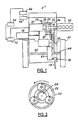
- Fig. 2 illustrates a planetary gear set for the vehicle show in Figure 1;
- Fig. 3 illustrates a general four wheel drive hybrid electric vehicle configuration; and
- Fig. 4 illustrates a flowchart illustrating operation of the braking system of the vehicle shown in Fig. 3.
-
- Figures 1 and 2 demonstrate a front wheel drive portion of a possible hybrid electric vehicle (HEV) configuration, specifically a parallel-series hybrid electric vehicle 7 (powersplit) configuration.
- A planetary gear set 20 mechanically couples a
gear carrier 22 to aninternal combustion engine 24 via a oneway clutch 26. The planetary gear set 20 also mechanically couples asun gear 28 to agenerator motor 30 and a ring (output)gear 32. Thegenerator motor 30 is also mechanically linked to agenerator brake 34 and is electrically linked to abattery 36. - A traction motor 38 is mechanically coupled to the
ring gear 32 of theplanetary gear set 20 via asecond gear set 40 and is electrically linked to thebattery 36. - The
ring gear 32 of the planetary gear set 20 and the traction motor 38 are mechanically coupled tofront drive wheels 42 viagear 59,transaxle 43 and axlehalf shafts - The planetary gear set 20 splits the
engine 24 output energy into a series path from theengine 24 to thegenerator motor 30 and a parallel path from theengine 24 to thedrive wheels 42. - The engine speed can be controlled by varying the split to the series path while maintaining the mechanical connection through the parallel path. The traction motor 38 augments the
engine 24 power to thedrive wheels 42 on the parallel path through thesecond gear set 40. The traction motor 38 also provides the opportunity to use energy directly from the series path, essentially running off power created by thegenerator motor 30. This reduces losses associated with converting energy into and out of chemical energy in thebattery 36 and allowing all the energy inengine 24, minus conversion losses, to reach thedrive wheels 42. - A vehicle system controller (VSC) 46 controls many components in HEV 7 by connecting to each component's controller. The engine control unit {ECU) 48 connects to the
engine 24 via a hardwire interface. The ECU 48 and VSC 46 can be based in the same unit, but are actually separate controllers. TheVSC 46 communicates with the ECU, as well as a battery control unit (BCU) 50 and a transaxle management unit (TMU) 52 through a communication network such as a controller area network (CAN) (not shown). The BCU 50 connects to thebattery 36 via a hardwire interface (not shown). The TMU 52 controls thegenerator motor 30 and traction motor 38 via a hardwire interface. - Referring additionally to Figure 3, the vehicle 7 according to the present invention additionally has a
rear axle 60.Rear axle 60 haswheels 64 andhalf shafts half shafts rear differential 70. Therear differential 70 is connected to adrive shaft 74 by a rear axleelectronic clutch 76. The rear axleelectronic clutch 76 can be a viscous-type clutch, which can additionally be electrically actuated upon command. Theclutch 76 is normally engaged by a rotational difference between therear wheels 64 andfront wheels 42. At other times the clutch is normally non-engaged. Thedrive shaft 74 is connected to a power take offunit 78. The power take offunit 78 torsionally connects thedrive shaft 74 with an output shaft from thetransaxle 43. - The vehicle 7 also has a conventional hydraulic braking system having a
master cylinder 90 which is connected to an anti-skid oranti-lock brake module 92. Thebrake module 92 allows themaster cylinder 90 to be directly connected tofoundation friction brakes 94 during normal brake operation. During ABS mode of operation, thebrake module 92 will isolate thefoundation brakes 94 from themaster cylinder 90 and will then modulate the mode of operation. - During ABS mode of operation,
brake module 92 will be controlled by abrake controller 100. Thebrake controller 100 will be in communication with wheel speed sensors (not shown) which monitor thefront wheels 42 andrear wheels 64.Brake controller 100 will be connected to the vehicle main communicative bus allowing it to communicate with other components as required, typically including theVSC 46. - Referring to Figure 4, in an operation due to a lift throttle incident, commonly referred to as compressive braking or over-run braking or by virtue of an operator-commanded brake signal, regenerative braking will be applied to the primary driven front axle. The regenerative braking will occur due to the action of the traction motor 38.
- If the driven
wheels 42 are on a low friction surface such as ice or gravel, a slip condition can occur, meaning that the wheels are slipping on the road surface. The slip condition is also commonly referred to as a locked condition wherein the brakes whether regenerative or friction lock or prevent thewheels 42 from rotation. - A slip condition can be sensed by virtue of control parameters which may include vehicle speed, wheel speed, regenerative torque and un-driven axle clutch torque. When a slip condition is sensed, the
VSC 46 will sense if theun-driven axle 60electronic clutch 76 is disengaged. - If the
electronic clutch 76 is disengaged theVSC 46 will signal it to engage. The engagement of the electronic clutch 76 will cause the regenerative braking to occur not only against the driven axle (half shafts 44, 45} but also against the torque of theun-driven wheels 42 via theun-driven axle 60. - Accordingly the torque available to stop the driven
wheels 42 will be halved and in many instances the drivenwheels 42 will be relieved from their slip condition. - Accordingly the slip condition indication for the
wheels 42 will be relieved and regenerative braking can continue.
In instances where both the front 42 andrear wheels 64 are on low friction surfaces theVSC 46 will signal the regenerative braking to be reduced. If a reduction of the regenerative braking does not relieve the slip conditions then theVSC 46 will signal thebrake controller 100 to engage into an ABS mode causing thebrake module 92 to isolate themaster cylinder 90 and to pulsate thefriction brakes 94. - When a slip condition is relieved, the
brake controller 100 can signal for thebrake module 90 to cease ABS actuation and regenerative braking can again be instigated by the traction motor 38. - The above-described embodiment of the invention is provided purely for purposes of example. For instance, the present invention can also be used on primarily rear wheel drive vehicles. Additionally, the present invention can be utilized in a vehicle where regenerative braking is applied on a secondary non-driven wheeled axle and a clutch can be actuated to torsionally connect the non-driven wheeled axle to the primary driven wheeled axle to relieve a slip condition. The person skilled in the art will understand that many other variations, modifications, and applications of the invention may be made.
Claims (10)
- A method of braking a vehicle (7) having a regenerative braked first wheeled axle (44)and a second wheeled axle (60) selectively connectable with the first wheeled axle (44) to provide a drivable connection therebetween, characterised in that the method comprises of sensing to determine if one or more of the first wheeled axle wheels (42) are slipping and if one or more of the first wheeled axle wheels (42) are slipping, driveably connecting the second wheeled axle (60) to said first wheeled axle (44).
- A method of braking a vehicle as claimed in claim 1 wherein the first axle is a driven axle (44).
- A method of braking a vehicle as claimed in claim 1 or in claim 2 wherein the method further comprises of reducing the regenerative braking of said first and second wheeled axles (44 and 60) below a slip condition of said first wheeled axle (44).
- A method of braking a vehicle as claimed in any of claims 1 to 3 wherein the method further comprises providing the first wheeled axle (44) with a second brake system (90,92,94,100) having an antilock mode of operation.
- A method of braking a vehicle as claimed in claim 4 wherein the method further comprises of shutting off the regenerative braking of the first wheeled axle (44) if slipping continues to occur after a reduction in regenerative braking and engaging the second brake system (90,92,94,100).
- A method as claimed in any of claims 1 to 5 wherein the first wheeled axle (44) is regeneratively braked to effect over-run braking of the vehicle (7).
- A method of braking a vehicle as claimed in any of claims 1 to 5 wherein regeneratively braking is applied in response to an operator command signal.
- A method of braking a vehicle as claimed in any of claims 1 to 7 wherein the first axle (44) is an electrically driven and electrically regenerative braked first wheeled axle (44) and the method further comprises of driveably connecting the second wheeled axle (60) to said first wheeled axle to electrically regeneratively brake said first and second wheeled axles (44 and 60).
- A method of braking a vehicle as claimed in any of claims 1 to 7, wherein the first wheeled axle is driven by an internal combustion engine (24).
- A vehicle (7) having an electrically driven and regeneratively braked first wheeled axle (44), a second wheeled axle (60) and a controller (46, 100) characterised in that the controller (46, 100) is operable to sense a slip condition of a wheel (42) of said first axle (44) when the first wheeled axle (44) is being electrically regeneratively braked and driveably connect the second wheeled axle (60) with said first wheeled axle (44) if said first wheeled axle (44) is being electrically regeneratively braked.
Applications Claiming Priority (2)
| Application Number | Priority Date | Filing Date | Title |
|---|---|---|---|
| US09/848,570 US6488344B2 (en) | 2001-05-03 | 2001-05-03 | Distribution of torque when driven wheels slip during regenerative braking |
| US848570 | 2001-05-03 |
Publications (3)
| Publication Number | Publication Date |
|---|---|
| EP1254803A2 true EP1254803A2 (en) | 2002-11-06 |
| EP1254803A3 EP1254803A3 (en) | 2003-12-03 |
| EP1254803B1 EP1254803B1 (en) | 2009-04-01 |
Family
ID=25303659
Family Applications (1)
| Application Number | Title | Priority Date | Filing Date |
|---|---|---|---|
| EP02252868A Expired - Lifetime EP1254803B1 (en) | 2001-05-03 | 2002-04-24 | Reduction of slip during regenerative braking |
Country Status (5)
| Country | Link |
|---|---|
| US (1) | US6488344B2 (en) |
| EP (1) | EP1254803B1 (en) |
| JP (1) | JP2003018701A (en) |
| CA (1) | CA2384714A1 (en) |
| DE (1) | DE60231774D1 (en) |
Cited By (1)
| Publication number | Priority date | Publication date | Assignee | Title |
|---|---|---|---|---|
| CN102700419A (en) * | 2012-06-06 | 2012-10-03 | 北京汽车新能源汽车有限公司 | Parallel-type braking energy recovery system and control method thereof |
Families Citing this family (44)
| Publication number | Priority date | Publication date | Assignee | Title |
|---|---|---|---|---|
| JP3811372B2 (en) * | 2001-05-30 | 2006-08-16 | トヨタ自動車株式会社 | Braking force control device for vehicle |
| DE10204723A1 (en) * | 2002-02-05 | 2003-08-14 | Continental Teves Ag & Co Ohg | Procedure for coordinating the use of a regenerative and an anti-lock system |
| JP2004155390A (en) * | 2002-11-08 | 2004-06-03 | Nissan Motor Co Ltd | Braking device for vehicle |
| US7500687B2 (en) * | 2004-01-31 | 2009-03-10 | Lockheed Martin Corporation | Vehicle suspension systems |
| US7441845B2 (en) * | 2004-09-13 | 2008-10-28 | Ford Global Technologies, Llc | Method for operating multiple axle regenerative braking in an automotive vehicle |
| US7311163B2 (en) * | 2004-11-16 | 2007-12-25 | Eaton Corporation | Regeneration and brake management system |
| US20070108838A1 (en) * | 2005-11-14 | 2007-05-17 | Ford Global Technologies, Llc | Regenerative braking control system and method |
| US7393065B2 (en) * | 2006-06-01 | 2008-07-01 | Lockheed Martin Corporation | Redundant braking system |
| US20080066613A1 (en) * | 2006-09-15 | 2008-03-20 | Lockheed Martin Corporation | Perforated hull for vehicle blast shield |
| US20080173167A1 (en) | 2006-09-15 | 2008-07-24 | Armor Holdings | Vehicular based mine blast energy mitigation structure |
| US20100025167A1 (en) * | 2008-07-31 | 2010-02-04 | Caterpillar Inc. | Braking system for an off-highway machine involving electric retarding integrated with service brakes |
| US8281908B2 (en) | 2008-08-29 | 2012-10-09 | Caterpillar Inc. | Brake cooling fluid diverter for an off-highway machine |
| US7956762B2 (en) * | 2008-09-15 | 2011-06-07 | Caterpillar Inc. | Method and apparatus for power generation failure diagnostics |
| US7918296B2 (en) | 2008-09-15 | 2011-04-05 | Caterpillar Inc. | Cooling system for an electric drive machine and method |
| US8410739B2 (en) | 2008-09-15 | 2013-04-02 | Caterpillar Inc. | Method and apparatus for determining the operating condition of generator rotating diodes |
| US8324846B2 (en) | 2008-09-15 | 2012-12-04 | Caterpillar Inc. | Electric drive retarding system and method |
| US8253357B2 (en) | 2008-09-15 | 2012-08-28 | Caterpillar Inc. | Load demand and power generation balancing in direct series electric drive system |
| US9063202B2 (en) | 2008-09-15 | 2015-06-23 | Caterpillar Inc. | Method and apparatus for detecting phase current imbalance in a power generator |
| US8054016B2 (en) | 2008-09-15 | 2011-11-08 | Caterpillar Inc. | Retarding energy calculator for an electric drive machine |
| US7996163B2 (en) | 2008-09-15 | 2011-08-09 | Caterpillar Inc. | Method and apparatus for detecting a short circuit in a DC link |
| US7795825B2 (en) | 2008-09-15 | 2010-09-14 | Caterpillar Inc | Over-voltage and under-voltage management for electric drive system |
| US8140206B2 (en) | 2008-09-15 | 2012-03-20 | Caterpillar Inc. | Engine load management for traction vehicles |
| US8612076B2 (en) * | 2008-10-31 | 2013-12-17 | Mahindra Reva Electric Vehicles Pvt. Ltd. | Antilock braking for vehicles |
| US8231183B2 (en) * | 2009-02-19 | 2012-07-31 | Ford Global Technologies | Traction control method |
| US8154140B2 (en) * | 2009-05-25 | 2012-04-10 | Harris Technology, Llc | Air regeneration for a moving vehicle |
| US8924120B2 (en) * | 2009-06-06 | 2014-12-30 | Ford Global Technologies, Llc | Regenerative brake control system and method |
| JP4913205B2 (en) * | 2009-12-18 | 2012-04-11 | 日立オートモティブシステムズ株式会社 | Electric vehicle braking control device |
| US8998353B2 (en) | 2010-09-07 | 2015-04-07 | GM Global Technology Operations LLC | Hybrid brake control |
| US8626368B2 (en) | 2010-09-07 | 2014-01-07 | Caterpillar Inc. | Electric drive power response management system and method |
| US8655528B2 (en) | 2011-01-31 | 2014-02-18 | GM Global Technology Operations LLC | Real-time allocation of actuator torque in a vehicle |
| KR101305260B1 (en) * | 2011-12-23 | 2013-09-06 | 대동공업주식회사 | Electric driving type Multi-purpose Utility vehicle with regenerative brake force distribute function and regenerative brake force distribute control method |
| DE102012210328A1 (en) * | 2012-06-19 | 2013-12-19 | Bayerische Motoren Werke Aktiengesellschaft | Vehicle stabilization for a hybrid vehicle with brake slip of the drive wheels or increased risk for this |
| KR102165371B1 (en) | 2013-03-14 | 2020-10-14 | 알리손 트랜스미션, 인크. | System and method for engine driveline disconnect during regeneration in hybrid vehicles |
| KR101519227B1 (en) * | 2013-10-18 | 2015-05-11 | 현대자동차주식회사 | Controlling method and system for operating Anti-lock Brake System of vehicle |
| EP3337700A4 (en) * | 2015-09-12 | 2019-06-12 | GM Global Technology Operations LLC | Vehicle having electric parking brake |
| KR102224145B1 (en) * | 2017-02-24 | 2021-03-05 | 현대자동차주식회사 | System and method for regenerative braking of vehicle |
| US10513265B2 (en) | 2017-03-13 | 2019-12-24 | Ford Global Technologies, Llc | Methods and system for hybrid vehicle regenerative braking |
| US10106150B2 (en) | 2017-03-13 | 2018-10-23 | Ford Global Technologies, Llc | Methods and system for operating a hybrid vehicle |
| US10118605B2 (en) | 2017-03-13 | 2018-11-06 | Ford Global Technologies, Llc | Methods and system for a hybrid vehicle |
| US10513254B2 (en) | 2017-03-13 | 2019-12-24 | Ford Global Technologies, Llc | Methods and system providing vehicle drift |
| US11820254B2 (en) * | 2018-05-03 | 2023-11-21 | Ford Global Technologies, Llc | Hybrid electric vehicle with torque split regenerative braking |
| JP7327256B2 (en) * | 2020-04-10 | 2023-08-16 | トヨタ自動車株式会社 | Regenerative braking control device for electric vehicle |
| CN112026527A (en) * | 2020-09-07 | 2020-12-04 | 中国第一汽车股份有限公司 | Control method, device and equipment for recovered torque and vehicle |
| US11724678B2 (en) * | 2020-10-30 | 2023-08-15 | Cummins Inc. | Method and system for performing regenerative braking with feedback from brake-traction control system |
Citations (9)
| Publication number | Priority date | Publication date | Assignee | Title |
|---|---|---|---|---|
| US4962969A (en) | 1988-09-30 | 1990-10-16 | Ford Motor Company | Adaptive controller for regenerative and friction braking system |
| US5269390A (en) | 1991-04-06 | 1993-12-14 | Lucas Industries Public Limited Company | Traction control system |
| US5294191A (en) | 1991-08-02 | 1994-03-15 | Brembo S.P.A. | Braking system for electrically driven vehicles |
| US5358084A (en) | 1993-01-19 | 1994-10-25 | Chrysler Corporation | Torque magnitude control using electrorheological fluids |
| US5378053A (en) | 1993-12-07 | 1995-01-03 | Alliedsignal Inc. | Maximized regenerative braking vehicle braking controller |
| US5421643A (en) | 1992-11-24 | 1995-06-06 | Itt Automotive Europe Gmbh | Brake system for automotive vehicles with electric drive |
| US5450324A (en) | 1993-01-07 | 1995-09-12 | Ford Motor Company | Electric vehicle regenerative antiskid braking and traction control system |
| US5573312A (en) | 1993-05-18 | 1996-11-12 | Smh Management Services Ag | Vehicle having an electric and mechanical braking system |
| US5615933A (en) | 1995-05-31 | 1997-04-01 | General Motors Corporation | Electric vehicle with regenerative and anti-lock braking |
Family Cites Families (8)
| Publication number | Priority date | Publication date | Assignee | Title |
|---|---|---|---|---|
| US4591016A (en) * | 1984-03-19 | 1986-05-27 | General Motors Corporation | Brake system in a vehicle hybrid drive arrangement |
| GB9320661D0 (en) | 1993-10-07 | 1993-11-24 | Lucas Ind Public Limited | Electric vehicle having abs |
| JP3585607B2 (en) | 1995-10-13 | 2004-11-04 | 本田技研工業株式会社 | Midship vehicle |
| JP3546277B2 (en) | 1996-01-29 | 2004-07-21 | トヨタ自動車株式会社 | Electric vehicle braking system |
| DE19607823C1 (en) | 1996-03-01 | 1997-08-21 | Bosch Gmbh Robert | Braking control device and method for electrically-driven motor vehicle |
| JP3541621B2 (en) | 1997-06-10 | 2004-07-14 | トヨタ自動車株式会社 | Vehicle braking system |
| US6099089A (en) | 1997-11-01 | 2000-08-08 | Ford Motor Company | Method and apparatus for regenerative and friction braking |
| US6203468B1 (en) * | 1998-11-18 | 2001-03-20 | Fuji Jukogyo Kabushiki Kaisha | Control device for hybrid vehicle and method thereof |
-
2001
- 2001-05-03 US US09/848,570 patent/US6488344B2/en not_active Expired - Lifetime
-
2002
- 2002-04-24 DE DE60231774T patent/DE60231774D1/en not_active Expired - Lifetime
- 2002-04-24 EP EP02252868A patent/EP1254803B1/en not_active Expired - Lifetime
- 2002-05-02 JP JP2002130290A patent/JP2003018701A/en active Pending
- 2002-05-03 CA CA002384714A patent/CA2384714A1/en not_active Abandoned
Patent Citations (10)
| Publication number | Priority date | Publication date | Assignee | Title |
|---|---|---|---|---|
| US4962969A (en) | 1988-09-30 | 1990-10-16 | Ford Motor Company | Adaptive controller for regenerative and friction braking system |
| US5269390A (en) | 1991-04-06 | 1993-12-14 | Lucas Industries Public Limited Company | Traction control system |
| US5294191A (en) | 1991-08-02 | 1994-03-15 | Brembo S.P.A. | Braking system for electrically driven vehicles |
| US5421643A (en) | 1992-11-24 | 1995-06-06 | Itt Automotive Europe Gmbh | Brake system for automotive vehicles with electric drive |
| US5551764A (en) | 1992-11-24 | 1996-09-03 | Itt Automotive Europe Gmbh | Brake system for automotive vehicles with electric drive |
| US5450324A (en) | 1993-01-07 | 1995-09-12 | Ford Motor Company | Electric vehicle regenerative antiskid braking and traction control system |
| US5358084A (en) | 1993-01-19 | 1994-10-25 | Chrysler Corporation | Torque magnitude control using electrorheological fluids |
| US5573312A (en) | 1993-05-18 | 1996-11-12 | Smh Management Services Ag | Vehicle having an electric and mechanical braking system |
| US5378053A (en) | 1993-12-07 | 1995-01-03 | Alliedsignal Inc. | Maximized regenerative braking vehicle braking controller |
| US5615933A (en) | 1995-05-31 | 1997-04-01 | General Motors Corporation | Electric vehicle with regenerative and anti-lock braking |
Cited By (1)
| Publication number | Priority date | Publication date | Assignee | Title |
|---|---|---|---|---|
| CN102700419A (en) * | 2012-06-06 | 2012-10-03 | 北京汽车新能源汽车有限公司 | Parallel-type braking energy recovery system and control method thereof |
Also Published As
| Publication number | Publication date |
|---|---|
| DE60231774D1 (en) | 2009-05-14 |
| US20020163250A1 (en) | 2002-11-07 |
| JP2003018701A (en) | 2003-01-17 |
| CA2384714A1 (en) | 2002-11-03 |
| US6488344B2 (en) | 2002-12-03 |
| EP1254803B1 (en) | 2009-04-01 |
| EP1254803A3 (en) | 2003-12-03 |
Similar Documents
| Publication | Publication Date | Title |
|---|---|---|
| EP1254803B1 (en) | Reduction of slip during regenerative braking | |
| CA2588092C (en) | Regeneration and brake management system | |
| US7458650B2 (en) | Regenerative braking system for motor vehicles | |
| EP1698507B1 (en) | Vehicle regenerative braking control apparatus and method | |
| US6959971B2 (en) | Vehicle braking apparatus | |
| CN109466536B (en) | Method for controlling electric four-wheel drive hybrid vehicle | |
| US8062175B2 (en) | Method and apparatus for optimizing braking control during a threshold braking event | |
| US6631960B2 (en) | Series regenerative braking torque control systems and methods | |
| US20060276289A1 (en) | Vehicle drive control apparatus and method | |
| US20070108838A1 (en) | Regenerative braking control system and method | |
| US20050151420A1 (en) | Hybrid electric vehicle powertrain with regenerative braking | |
| US11225238B2 (en) | System and method for increasing regenerative braking in a rear-wheel-drive-based platform with four-wheel-drive capability | |
| CN102219018A (en) | System to distribute propulsion in a vehicle | |
| JP2007060761A (en) | Deceleration controller for hybrid car | |
| CN102442310B (en) | Method and driveline stability control system for a vehicle | |
| JP2008056151A (en) | Vehicular braking control device | |
| CN106585403A (en) | Driving system for electric vehicle and electric vehicle driving method | |
| US20090107741A1 (en) | Limited Slip Differential For Electric Vehicle | |
| CN104859657A (en) | Hybrid vehicle and method of operation | |
| CN104395124B (en) | For the hybrid electric vehicle Vehicle Stability System when driving wheel brake slip or dangerous raising as noted above | |
| JPH04103433A (en) | Driving force distribution control device for four-wheel drive vehicle | |
| US20020163251A1 (en) | Regenerative brake system architecture for an electric or hybrid electric vehicle | |
| CN102442306B (en) | System and method for controlling stability of hybrid power electric vehicle | |
| JP2006352954A (en) | Regenerative braking system | |
| Guo et al. | Hierarchical control research for composite braking system of an electric vehicle |
Legal Events
| Date | Code | Title | Description |
|---|---|---|---|
| PUAI | Public reference made under article 153(3) epc to a published international application that has entered the european phase |
Free format text: ORIGINAL CODE: 0009012 |
|
| AK | Designated contracting states |
Kind code of ref document: A2 Designated state(s): AT BE CH CY DE DK ES FI FR GB GR IE IT LI LU MC NL PT SE TR |
|
| AX | Request for extension of the european patent |
Free format text: AL;LT;LV;MK;RO;SI |
|
| PUAL | Search report despatched |
Free format text: ORIGINAL CODE: 0009013 |
|
| AK | Designated contracting states |
Kind code of ref document: A3 Designated state(s): AT BE CH CY DE DK ES FI FR GB GR IE IT LI LU MC NL PT SE TR |
|
| AX | Request for extension of the european patent |
Extension state: AL LT LV MK RO SI |
|
| RIC1 | Information provided on ipc code assigned before grant |
Ipc: 7B 60L 7/26 B Ipc: 7B 60L 7/10 A |
|
| 17P | Request for examination filed |
Effective date: 20040428 |
|
| AKX | Designation fees paid |
Designated state(s): DE FR GB |
|
| GRAP | Despatch of communication of intention to grant a patent |
Free format text: ORIGINAL CODE: EPIDOSNIGR1 |
|
| GRAS | Grant fee paid |
Free format text: ORIGINAL CODE: EPIDOSNIGR3 |
|
| GRAA | (expected) grant |
Free format text: ORIGINAL CODE: 0009210 |
|
| AK | Designated contracting states |
Kind code of ref document: B1 Designated state(s): DE FR GB |
|
| REG | Reference to a national code |
Ref country code: GB Ref legal event code: FG4D |
|
| REF | Corresponds to: |
Ref document number: 60231774 Country of ref document: DE Date of ref document: 20090514 Kind code of ref document: P |
|
| PLBE | No opposition filed within time limit |
Free format text: ORIGINAL CODE: 0009261 |
|
| STAA | Information on the status of an ep patent application or granted ep patent |
Free format text: STATUS: NO OPPOSITION FILED WITHIN TIME LIMIT |
|
| 26N | No opposition filed |
Effective date: 20100105 |
|
| REG | Reference to a national code |
Ref country code: DE Ref legal event code: R082 Ref document number: 60231774 Country of ref document: DE Representative=s name: DOERFLER, THOMAS, DR.-ING., DE |
|
| REG | Reference to a national code |
Ref country code: FR Ref legal event code: PLFP Year of fee payment: 15 |
|
| REG | Reference to a national code |
Ref country code: FR Ref legal event code: PLFP Year of fee payment: 16 |
|
| PGFP | Annual fee paid to national office [announced via postgrant information from national office to epo] |
Ref country code: FR Payment date: 20170322 Year of fee payment: 16 |
|
| PGFP | Annual fee paid to national office [announced via postgrant information from national office to epo] |
Ref country code: GB Payment date: 20170328 Year of fee payment: 16 |
|
| GBPC | Gb: european patent ceased through non-payment of renewal fee |
Effective date: 20180424 |
|
| PG25 | Lapsed in a contracting state [announced via postgrant information from national office to epo] |
Ref country code: GB Free format text: LAPSE BECAUSE OF NON-PAYMENT OF DUE FEES Effective date: 20180424 |
|
| PG25 | Lapsed in a contracting state [announced via postgrant information from national office to epo] |
Ref country code: FR Free format text: LAPSE BECAUSE OF NON-PAYMENT OF DUE FEES Effective date: 20180430 |
|
| PGFP | Annual fee paid to national office [announced via postgrant information from national office to epo] |
Ref country code: DE Payment date: 20210318 Year of fee payment: 20 |
|
| REG | Reference to a national code |
Ref country code: DE Ref legal event code: R071 Ref document number: 60231774 Country of ref document: DE |