EP1255221A2 - Method and apparatus for document processing - Google Patents
Method and apparatus for document processing Download PDFInfo
- Publication number
- EP1255221A2 EP1255221A2 EP02252629A EP02252629A EP1255221A2 EP 1255221 A2 EP1255221 A2 EP 1255221A2 EP 02252629 A EP02252629 A EP 02252629A EP 02252629 A EP02252629 A EP 02252629A EP 1255221 A2 EP1255221 A2 EP 1255221A2
- Authority
- EP
- European Patent Office
- Prior art keywords
- operator
- transport
- display unit
- message
- messages
- Prior art date
- Legal status (The legal status is an assumption and is not a legal conclusion. Google has not performed a legal analysis and makes no representation as to the accuracy of the status listed.)
- Granted
Links
Images


Classifications
-
- G—PHYSICS
- G06—COMPUTING; CALCULATING OR COUNTING
- G06K—GRAPHICAL DATA READING; PRESENTATION OF DATA; RECORD CARRIERS; HANDLING RECORD CARRIERS
- G06K17/00—Methods or arrangements for effecting co-operative working between equipments covered by two or more of main groups G06K1/00 - G06K15/00, e.g. automatic card files incorporating conveying and reading operations
- G06K17/0022—Methods or arrangements for effecting co-operative working between equipments covered by two or more of main groups G06K1/00 - G06K15/00, e.g. automatic card files incorporating conveying and reading operations arrangements or provisious for transferring data to distant stations, e.g. from a sensing device
Definitions
- the present invention relates generally to financial document transport and processing systems. More particularly, the invention relates to an improved document processing system and methods employing a small, low cost wireless display unit which can be worn or carried by an operator in order to receive messages notifying the operator of a need for intervention.
- An item transport used in financial document processing systems to receive, process and sort documents, typically comprises an input section in which a batch of documents is placed for processing, a transport path for transporting the documents through various processing steps, a sorting area where the documents are sorted into different pockets after processing, and display and input sections where an operator is able to read displayed messages and enter information and commands.
- An operator is frequently called on to perform tasks at different areas of the transport.
- a typical item transport is quite large and requires an operator to walk a significant distance to get from one side or end of the transport to the other. For example, an operator may be working at the sorting area of the transport when a problem occurs, causing the transport to interrupt processing and display an error message.
- the operator must walk to the display area, read the error message and then proceed back to the sorting area or to another identified area in order to correct the problem.
- the need for the operator to walk back and forth along the transport to receive messages and then perform tasks related to those messages interferes with operator efficiency.
- the present invention recognizes that there is a need for a system to provide instructions to an operator of a document processing system, which may advantageously employ a low cost, rugged wireless display unit with relatively low power usage, able to receive transmissions anywhere in the vicinity of a processing machine without requiring a line of sight transmission.
- such a system advantageously allows an operator to be notified of problems and their locations wherever he or she happens to be with respect to the transport.
- the methods used for notification will not interfere with the operator's freedom of movement and may advantageously be accomplished using a low cost device in order to minimize expense and to insure that breakage or loss of devices would not cause undue hardship.
- the devices used will also advantageously minimize battery drain in order to allow the operator to work without being interrupted by a need to replace batteries.
- a document processing system may suitably include an item transport controlled by a transport controller which may suitably be a personal computer (PC).
- the transport controller communicates with a user interface for displaying operator messages and receiving operator inputs.
- the user interface may suitably include a monitor for displaying messages and a keyboard to allow operator inputs.
- the transport controller also communicates with a transmitter interface for sending messages to and receiving commands or other operator inputs from each of a plurality of wireless operator display units which may be carried or worn by the operators.
- the operator display units are preferably inexpensive and rugged, and may suitably be implemented through the appropriate adaptation of electronic shelf labels such as are presently used in retail stores to receive and display price information.
- Each of the operator display units has a unique address so that a message directed toward a particular unit includes the unit address and the message, so that only the intended unit will display the message. This ability is important where multiple units are employed in the same processing environment as may occur in major check or credit processing operations.
- Each of the operator display units is preferably adapted to allow the operator to transmit messages back to the transport controller through the use of pushbuttons or other simple interface devices. When an exception occurs affecting an item transport, the transport controller suspends item processing, displays a message using the monitor and also transmits an abbreviated message to an operator display unit associated with the affected transport.
- the message may be sent directly or by means of a server controlling access to a transmitter interface shared by a number of different transports, the transports being connected to the server by means of a local area network.
- the transport controller Upon sending the operator display message, the transport controller begins transmitting status messages to the operator display unit. Once the operator has cleared the exception, he or she directs the operator display unit to signal the transport controller that the exception has been cleared, typically by pressing a pushbutton on the operator display unit. It is also possible to signal that the exception has been cleared by pressing a button on the transport pocket or by pressing a key on a keyboard providing an interface to the transport controller.
- the operator display unit responds to a status request by signaling the transport processor that the exception has been cleared.
- the transport processor then performs another check for exceptions, and either resumes processing or performs further exception handling depending on whether exceptions exist.
- a document processing system comprising : a document transport ; a transport controller for directing the operation of the document transport, the transport controller being operative to sense exceptions and to generate operator messages in response to the exceptions; a transmitter interface for receiving operator messages from the transport controller and wirelessly transmitting the messages; and an operator display unit for wirelessly receiving operator display messages from the transmitter interface and visually displaying the messages for an operator.
- a method of document processing exception handling comprising the steps of: suspending document processing upon detection of an exception; wirelessly transmitting a visual operator message describing the exception to an operator display unit; and receiving a notification that the exception has been cleared
- Fig. 1 illustrates a document processing system 100 in accordance with the present invention.
- the system 100 includes an item processing transport 102 for processing and sorting documents.
- the transport 102 includes a hopper 104, a transport path 106 and sorting pocket modules 107A and 107B.
- the sorting pocket module 107A includes sorting pockets 108A-108D and the sorting pocket module 107B includes sorting pockets 108E-108H.
- the sorting pocket modules 107A and 107B are physically distinct units of machinery, each containing four pockets, but in document processing operations the pockets 108A-108H are grouped in accordance with the needs of the processing operation being performed.
- a particular operation may use the pockets 108A-108D as a set of pockets for grouping of documents, while another operation at a later stage of processing may use the set of pockets 108A-108B, while still another operation uses the pockets 108A-108H.
- the number of sorting pocket modules which may be used is not limited to the two represented by the modules 107A and 107B.
- the transport 102 may include as many sorting pocket modules as are needed. For example, many large item transports may have 12 or more sorting pocket modules, each module having four pockets, for a total of 48 or more pockets. In such a case, the number of sorting pocket modules add substantially to the length of the transport 102, increasing the time required for an operator to walk between two different widely separated parts of the transport 102.
- the transport 102 is controlled by a transport controller 110 which may suitably be a programmed personal computer (PC) which controls the operation of the transport 102 and which receives inputs from an operator through a keyboard 112 and displays operator messages through a monitor 114.
- the transport 102 also includes a transmitter interface 116 communicating with the transport controller 110, receiving operator messages from the transport controller 110 and transmitting the messages through an antenna 117 to an operator display unit 118 carried or worn by the operator.
- exceptions and problems, such as document jams occur in the area of the pockets such as the pockets 108A-108H, and transmitting messages to the operator display unit 118 saves the operator from walking to the monitor to receive an error message and then returning to the area of the pockets 108A-108H to deal with the problem.
- Fig. 2 is a detailed functional view of a document processing system 200 in accordance with the present invention.
- the document processing system 200 includes an item processing transport 202 including a document hopper 204, document feeder 205, transport path 206 and sorting pockets 208A-H.
- the sorting pockets 208A-208H are shown here by way of example, and are discussed here as part of a single operational group, but it will be recognized that the transport 202 may include more or fewer pockets and that operational groupings of pockets will be determined by the needs of the processing operation being undertaken.
- the transport 202 also includes an operator interface 210 including a keyboard 212 and monitor 214.
- the operator interface 210 may be used for entering data to be entered on a document, such as the amount of the document, and is also used to receive information about the status of the transport 202 and to enter commands directing operation of the transport 202.
- the transport 202 also includes a reading module 216, an image capture module 218, an encoding module 220 and an endorsing module 222.
- a transport such as the transport 202 to include additional modules, for example an ultraviolet snippet module for use in detecting security features appearing in ultraviolet ink, an endorsement capture module, a micro verifier module, a microfilmer module, or any of a number of optional modules.
- additional modules for example an ultraviolet snippet module for use in detecting security features appearing in ultraviolet ink, an endorsement capture module, a micro verifier module, a microfilmer module, or any of a number of optional modules.
- Operation of the transport 202 is controlled by a transport controller 224 which displays operator messages using the monitor 214 and receives operator inputs from the keyboard 212.
- the transport controller 224 also directs the operation of the document feeder 205, transport path 206, sorting pocket modules 208A-H and the modules 216, 218, 220 and 222, and receives and processes data generated by processing of documents.
- the transport controller 224 also communicates with a transmitter interface 226 in order to convey operator messages to an operator display unit 228 which receives operator messages transmitted via an antenna 230 connected to the transport controller 224.
- an item processing transport such as the transport 202 requires only a single operator, so that the transport controller 224 sends messages addressed to only one operator display unit 228.
- each message to the intended operator display unit 228 it is possible for the transport 202 to operate within radio range of other similar transports, each communicating to its own operator display unit, without misrouting of messages or other interference.
- the operator display unit 228 will display only messages including its address and will ignore messages addressed to other units.
- the affected module sends a message to the transport controller 224, which suspends operation of the transport 102, displays a message on the monitor 214 and uses the transmitter interface 226 to send an operator message to the operator display unit 228.
- the operator proceeds to the indicated area of the transport 202 and corrects the problem.
- the operator then preferably presses a button on the display unit 228, which sends a command to the transport controller 224 to resume operation.
- the operator may also alternatively press a pocket button or press an "Enter" key or another predetermined key on the keyboard 212 in order to resume operation.
- an operator audio message unit 232 may be employed as an alternative to, or in addition to, the display unit 228.
- the operator audio message unit 230 preferably comprises a receiver 234 and a headset 236.
- the transmitter interface 226 is modified to include a voice synthesizer and an audio transmitter, which will be described more fully below in connection with Fig. 7.
- the transmitter interface 226 uses the voice synthesizer to create a voice message constituting the desired operator message.
- the transmitter interface 226 uses the audio transmitter to transmit the desired voice message to the operator audio message unit 232.
- the document processing system 200 provides significant savings of time and effort over prior art systems, which require the operator to walk to a display in order to read a message describing the problem and then walk back to the pocket area if, as is likely, the problem affects one of the pockets. Eliminating or substantially reducing the need to walk back and forth between the information display and the area where the problem exists significantly increases the productivity of the operator.
- a plurality of transports may share a single transmitter interface.
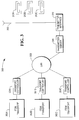
- Fig. 3 illustrates a document processing system 300 including transports 302A-302C, controlled by transport controllers 304A-304C, respectively.
- Each of the transport controllers 304A-304C is connected to a transmitter server 306 by a local area network 308. It will be recognized that the transmitter server 306 need not be exclusively dedicated to transmitting, but may be a multifunction server.
- the transmitter server 306 is in turn connected to a transmitter interface 310 and controls the operation of the transmitter interface 310 in response to commands from the transport controllers 304A-304C, also transferring data from the transmitter interface 310 to the transport controllers 304A-304C.
- Each of the transports 302A-302C is associated with one of the operator display units 312A-312C.
- the transport controller 304A prepares an operator message addressed to the operator display unit 312A.
- the transport controller 304A then passes the message to the transmitter server 306, which sends the message using the transmitter interface 308 and antenna 309. Because the message is addressed to the operator display unit 312A, the operator display units 312B and 312C will not be affected.
- a plurality of transports such as the transports 302A-302C are able to operate within radio range of one another and are able to share a transmitter interface, each transport being able to communicate with its own dedicated operator display unit without interfering with the operation of operator display units associated with the other transports.
- Fig. 4 illustrates a front view of an operator display unit 400 in accordance with the present invention.
- the transportable display unit 400 includes an LCD display 402, shown here as displaying an operator message "PKT 36 IS FULL," indicating to the operator that pocket 36 of the item transport sending the message is full.
- the unit 400 also includes a wrist strap 404, preferably including VELCRO, to allow secure attachment for wearing by the operator, as well as easy removal.
- First and second pushbuttons 406 and 408 are also shown and may be utilized as discussed in greater detail below.
- the display unit 400 includes a display unit processor 502, which may suitably be implemented as a digital signal processor, and a communications interface 504 for communicating with a transmitter interface such as the transmitter interface 226.
- the communications interface 504 includes a receiver 506 and an antenna 507
- the antenna 507 is built into and preferably enclosed entirely within the display unit 400.
- the display unit 400 includes various other electronic components, including a battery 508, and the LCD display 402.
- the display unit 400 further includes read-only memory 512 for permanent storage of instructions and other data, as well as data registers 514A-514D for storing message information received from the transmitter interface 226.
- the data registers 514A-514D are preferably implemented using volatile memory.
- the first pushbutton 406 allows an operator to direct the processor 502 to select the contents of any one of the registers 514A-514D for display. Repeated presses of the pushbutton 406 cycle between the different registers 514A-514D. In this way, the operator display unit 400 is able to receive messages longer than could otherwise be displayed on the LCD display 402, allowing the operator to read such messages by cycling through successive screens.
- a second pushbutton 408 is provided to allow the operator to signal the transport 202 to resume operation.
- the display unit 400 also includes writable memory, shown here as RAM, 518 in addition to the volatile memory used for the data registers 514A-514D.
- the RAM 518 is used for short-term data storage in performing the normal operations of the operator display unit 400.
- the processor 502 displays the message using the LCD display 402.
- the processor 502 may also direct an audible signal using an alerter 519.
- the operator display unit 400 is preferably implemented as a passive device.
- the display unit 400 does not independently transmit data to the transmitter interface 226, but sends signals only in response to status requests received from the transmitter interface 226.
- the transport controller 224 directs the transmitter interface 226 to transmit an operator message to the display unit 400
- the controller 224 preferably also directs the transmitter interface 226 to send repeated status requests by polling the display unit 400, in order to determine if the operator has pressed the second button 516 to command the transport controller 224 to resume operation of the transport.
- the display unit 400 employs a modulated backscatter approach to answer the status request, reflecting the transmission back to the transmitter interface 226.
- the transmitter interface 226 Upon receiving the reflected answer to the status request, the transmitter interface 226 sends a signal to the transport controller 224, which responds by proceeding to the next step in the exception handling operation, typically by examining the status of the transport 202 to determine if any exceptions remain and by resuming operation of the transport 202 or transmitting a follow-up message to the operator, as appropriate. Under normal circumstances, the transport controller 224 will send status requests only for a short time, during periods when operator intervention has been requested. When normal operation is resumed, the transport controller 224 stops sending status requests.
- the display unit 400 including a transmitter 520. If such an implementation is chosen, the display unit 500 can send unsolicited messages to the transport controller 524, providing greater flexibility in operation at the expense of added cost and complexity of the display unit 400.
- the display unit 400 is preferably implemented by adapting an electronic shelf label, presently used in retail environments to receive radio frequency information messages comprising product description and price information and to respond to queries through the use of modulated backscatter.
- An electronic shelf label can be purchased from a suitable vendor and adapted for use as an operator display unit such as the display unit 400 simply by selecting the messages to be transmitted to the unit.
- a modified design may be developed to more closely adapt the display unit to the requirements of the item processing environment.
- the data registers 514A-514D are preferably implemented as flash memory when the device is used as an electronic shelf label, because the contents of the registers change relatively infrequently. In an item processing environment, the contents of the registers 514A-514D change with much greater frequency, so that an institution might find it desirable to design an operator display unit 500 using RAM to implement the data registers 514A-514D.
- Fig. 6 provides a functional illustration of a transport controller which may be employed as the transport controller 224.
- the transport controller 224 includes a microcontroller 602 connected to a transport interface 604 and a user interface 606.
- the user interface 606 provides communication with a keyboard and monitor, such as the keyboard 212 and monitor 214 of Fig. 2, as well as a mouse or other desired user interface devices.
- the transport controller also includes a processor 608, memory 610 and extended database storage 612.
- a visual message database 613 and an audio message database 614 preferably reside in the storage 612.
- the processor 608 implements various functions used to control the transport operation and operator communication.
- the functions include a flow control function 615 for control of information and commands used by the transport controller.
- An item data and memory image function 616 are also implemented for reading and processing encoded item information as well as for capturing and storing item images.
- An item control function 618 is also implemented for directing transport of the items to be processed, as well as an error message function 620.
- the flow control function directs the item control function to suspend processing of items, and notifies the error message function that an error has occurred.
- the error message function 620 receives error information from the flow control function 615 and prepares error messages based on the error reports.
- Visual error messages are prepared by using the error information to look up appropriate messages in the visual message database 613 and audio error messages are prepared by using the error information to look up appropriate messages in the audio message database 614.
- the error message function 620 displays the error message locally and then provides the error messages to a transmitter control function 622, which formats the error messages into error message transmissions directed toward appropriate operator display units, and sends the error message transmissions to a transmitter control such as the transmitter interface 226.
- Fig. 7 illustrates additional details of the transmitter interface 226 of Fig. 2.
- the transmitter interface 226 is suitably adapted from an electronic price label communication device and includes a computer 702 and communication base station (CBS) 704.
- the computer 702 includes a storage medium 706, which may suitably be a disk drive, on which is stored an operator display unit data file 708 containing addresses of all display units such as the display unit 228, as well as data to be transmitted to each display unit.
- the computer 702 implements electronic display unit control software including a data scheduler 710 which manages transmission and reception of messages to and from each of the display units, as well as CBS management software 712, which directs the operations of the CBS 704 and which constructs messages to and interprets messages from the display units.
- the computer 702 also implements communication interface software 714, which manages the receipt of instructions from other elements of the document processing system and passes messages received from the display units to appropriate elements of the document processing system.
- the computer 702 stores the messages in the operator display unit data file 708, each message being indexed to the correct display unit address.
- the data scheduler software 710 retrieves the messages and addresses from the data file 708 when one or more messages are scheduled to be sent, formats the messages and passes them to the CBS manager software 710.
- the CBS manager software 710 formats the messages for transmission by the CBS 704 and passes them to the CBS 704.
- the CBS 704 translates the messages to a signal using CBS circuitry 716, and sends the signal using a CBS transmit antenna 718.
- the CBS transmit antenna 718 and CBS circuitry 716 are also adapted to receive signals from the operator display units in the form of modulated backscatter.
- a signal is received from an operator display unit, the signal is converted to a message by the CBS circuitry 716, which passes the message to the data scheduler 710.
- the data scheduler 710 in turn passes the message to the CBS manager 712.
- the CBS manager software 710 passes the message to the communication interface software 714, which in turn passes the message to the transport controller 224.
- the computer 702 includes software adapted from management of electronic price labels and the CBS 704 is an adaptation of a CBS used to communicate with electronic price labels.
- the communication interface 226 can be constructed through the purchase and adaptation of readily available devices.
- Electronic price labels are used in the typical retail store environment in great numbers over a wide area, so that a number of CBS modules such as the CBS module 704 are employed to communicate with and control them.
- the number of electronic labels and the range over which they are to be used is likely to be smaller than in the typical retail store environment, so that it may often be possible or typical to employ only one CBS module such as the module 704.
- the interface 226 also includes an audio communication module 720 including a voice synthesizer 722 and an audio transmitter 724, as well as an audio transmission antenna 725.
- the computer 702 preferably includes a text to speech module 722.
- the transport controller 224 sends the message to the computer 702.
- the computer 702 uses the text to speech module 722 to produce an audio message.
- the computer 702 finds the address of the message unit to which the message unit is to be sent in an audio message unit address database 728, adds the address to the audio message, and sends the audio message to the audio communication module 720.
- the audio communication module 720 uses the speech synthesizer 722 to convert the audio message to speech, and transmits the message using the audio transmitter 724.
- Fig. 8 illustrates a process 800 for exception handling for a single item transport, as in Fig. 2, or a group of item transports, as in Fig. 3, in accordance with the present invention.
- an identification table is established associating each transport with an operator display unit.
- the item transport suspends processing of items in response to an exception.
- the item transport may suitably be similar to the transport 202, or may be any of a number of item transport designs adapted to suspend operation in response to an exception and sense the nature of the exception.
- an error message is constructed.
- the error message is preferably created by first retrieving data from an error database associating each exception with a specific error message and then adding data identifying the item transport affected and the operator display unit to receive the message, and formatting the message for transmission.
- the message is wirelessly transmitted to an operator display unit, preferably a small, low cost wearable unit similar to the unit 400 of Figs 4 and 5.
- the message may be transmitted using a transmitter interface dedicated to a single item transport, or may alternatively be passed to a server controlling access to a shared transmitter interface.
- the transport sends repeated status requests to the operator display unit to determine if the operator has signaled for the transport to resume operation.
- the transport in response to a notification by the operator to resume operation, the transport examines sensors related to the exception to determine if the exception has been cleared. If the exception has been cleared, the process proceeds to step 850 and the transport sends a transmission clearing the error message on the operator display unit and resumes operation. If the exception has not been cleared, the process proceeds to step 812 and the transport examines a correction attempt count to determine if a predetermined number of allowable attempts to correct the exception has been made. If the maximum number of attempts has been made, the process proceeds to step 860 and the operator is instructed that the maximum number of correction attempts has been made and is instructed to proceed to a monitor for detailed instructions. The process then terminates at step 870.
- step 814 the correction attempt count is incremented and a supplemental error message is transmitted, either giving additional details about the exception or simply alerting the operator that the exception has not been corrected.
- the process returns to step 810.
Abstract
Description
- The present invention relates generally to financial document transport and processing systems. More particularly, the invention relates to an improved document processing system and methods employing a small, low cost wireless display unit which can be worn or carried by an operator in order to receive messages notifying the operator of a need for intervention.
- An item transport, used in financial document processing systems to receive, process and sort documents, typically comprises an input section in which a batch of documents is placed for processing, a transport path for transporting the documents through various processing steps, a sorting area where the documents are sorted into different pockets after processing, and display and input sections where an operator is able to read displayed messages and enter information and commands. An operator is frequently called on to perform tasks at different areas of the transport. A typical item transport is quite large and requires an operator to walk a significant distance to get from one side or end of the transport to the other. For example, an operator may be working at the sorting area of the transport when a problem occurs, causing the transport to interrupt processing and display an error message. The operator must walk to the display area, read the error message and then proceed back to the sorting area or to another identified area in order to correct the problem. The need for the operator to walk back and forth along the transport to receive messages and then perform tasks related to those messages interferes with operator efficiency.
- The present invention recognizes that there is a need for a system to provide instructions to an operator of a document processing system, which may advantageously employ a low cost, rugged wireless display unit with relatively low power usage, able to receive transmissions anywhere in the vicinity of a processing machine without requiring a line of sight transmission.
- Among its several aspects, such a system advantageously allows an operator to be notified of problems and their locations wherever he or she happens to be with respect to the transport. Ideally, the methods used for notification will not interfere with the operator's freedom of movement and may advantageously be accomplished using a low cost device in order to minimize expense and to insure that breakage or loss of devices would not cause undue hardship. The devices used will also advantageously minimize battery drain in order to allow the operator to work without being interrupted by a need to replace batteries.
- A document processing system according to one aspect of the present invention may suitably include an item transport controlled by a transport controller which may suitably be a personal computer (PC). The transport controller communicates with a user interface for displaying operator messages and receiving operator inputs. The user interface may suitably include a monitor for displaying messages and a keyboard to allow operator inputs. The transport controller also communicates with a transmitter interface for sending messages to and receiving commands or other operator inputs from each of a plurality of wireless operator display units which may be carried or worn by the operators. The operator display units are preferably inexpensive and rugged, and may suitably be implemented through the appropriate adaptation of electronic shelf labels such as are presently used in retail stores to receive and display price information. Each of the operator display units has a unique address so that a message directed toward a particular unit includes the unit address and the message, so that only the intended unit will display the message. This ability is important where multiple units are employed in the same processing environment as may occur in major check or credit processing operations. Each of the operator display units is preferably adapted to allow the operator to transmit messages back to the transport controller through the use of pushbuttons or other simple interface devices. When an exception occurs affecting an item transport, the transport controller suspends item processing, displays a message using the monitor and also transmits an abbreviated message to an operator display unit associated with the affected transport. The message may be sent directly or by means of a server controlling access to a transmitter interface shared by a number of different transports, the transports being connected to the server by means of a local area network. Upon sending the operator display message, the transport controller begins transmitting status messages to the operator display unit. Once the operator has cleared the exception, he or she directs the operator display unit to signal the transport controller that the exception has been cleared, typically by pressing a pushbutton on the operator display unit. It is also possible to signal that the exception has been cleared by pressing a button on the transport pocket or by pressing a key on a keyboard providing an interface to the transport controller. Once the operator has pressed the pushbutton or otherwise signaled that the exception has been cleared, the operator display unit responds to a status request by signaling the transport processor that the exception has been cleared. The transport processor then performs another check for exceptions, and either resumes processing or performs further exception handling depending on whether exceptions exist.
- According to a first aspect of the present invention there is provided a document processing system, comprising : a document transport ; a transport controller for directing the operation of the document transport, the transport controller being operative to sense exceptions and to generate operator messages in response to the exceptions; a transmitter interface for receiving operator messages from the transport controller and wirelessly transmitting the messages; and an operator display unit for wirelessly receiving operator display messages from the transmitter interface and visually displaying the messages for an operator.
- According to a second aspect of the present invention there is provided a method of document processing exception handling comprising the steps of: suspending document processing upon detection of an exception; wirelessly transmitting a visual operator message describing the exception to an operator display unit; and receiving a notification that the exception has been cleared
- An embodiment of the present invention will now be described, by way of example, with reference to the accompanying drawings, in which:
- Fig. 1 illustrates a document processing system in accordance with the present invention;
- Fig. 2 illustrates functional details of a document processing system in accordance with the present invention;
- Fig. 3 illustrates a document processing system including multiple item transports in accordance with the present invention;
- Fig. 4 illustrates an operator display unit in accordance with the present invention;
- Fig. 5 illustrates additional details of an operator display unit in accordance with the present invention;
- Fig. 6 illustrates functional details of a transport controller in accordance with the present invention;
- Fig. 7 illustrates a transmitter interface in accordance with the present invention; and
- Fig. 8 illustrates a process of transport exception handling in accordance with the present invention.
-
- Fig. 1 illustrates a
document processing system 100 in accordance with the present invention. Thesystem 100 includes anitem processing transport 102 for processing and sorting documents. Thetransport 102 includes ahopper 104, atransport path 106 and sortingpocket modules sorting pocket module 107A includessorting pockets 108A-108D and thesorting pocket module 107B includessorting pockets 108E-108H. Thesorting pocket modules pockets 108A-108H are grouped in accordance with the needs of the processing operation being performed. For example, a particular operation may use thepockets 108A-108D as a set of pockets for grouping of documents, while another operation at a later stage of processing may use the set ofpockets 108A-108B, while still another operation uses thepockets 108A-108H. It will be recognized that the number of sorting pocket modules which may be used is not limited to the two represented by themodules transport 102 may include as many sorting pocket modules as are needed. For example, many large item transports may have 12 or more sorting pocket modules, each module having four pockets, for a total of 48 or more pockets. In such a case, the number of sorting pocket modules add substantially to the length of thetransport 102, increasing the time required for an operator to walk between two different widely separated parts of thetransport 102. - The
transport 102 is controlled by atransport controller 110 which may suitably be a programmed personal computer (PC) which controls the operation of thetransport 102 and which receives inputs from an operator through akeyboard 112 and displays operator messages through amonitor 114. Thetransport 102 also includes atransmitter interface 116 communicating with thetransport controller 110, receiving operator messages from thetransport controller 110 and transmitting the messages through anantenna 117 to anoperator display unit 118 carried or worn by the operator. Frequently, exceptions and problems, such as document jams, occur in the area of the pockets such as thepockets 108A-108H, and transmitting messages to theoperator display unit 118 saves the operator from walking to the monitor to receive an error message and then returning to the area of thepockets 108A-108H to deal with the problem. - Fig. 2 is a detailed functional view of a
document processing system 200 in accordance with the present invention. Thedocument processing system 200 includes anitem processing transport 202 including adocument hopper 204,document feeder 205,transport path 206 andsorting pockets 208A-H. Thesorting pockets 208A-208H are shown here by way of example, and are discussed here as part of a single operational group, but it will be recognized that thetransport 202 may include more or fewer pockets and that operational groupings of pockets will be determined by the needs of the processing operation being undertaken. - The
transport 202 also includes anoperator interface 210 including akeyboard 212 andmonitor 214. Theoperator interface 210 may be used for entering data to be entered on a document, such as the amount of the document, and is also used to receive information about the status of thetransport 202 and to enter commands directing operation of thetransport 202. Thetransport 202 also includes areading module 216, animage capture module 218, anencoding module 220 and anendorsing module 222. While thereading module 216,image capture module 218,encoding module 220 andendorsing module 222 are shown here by way of example, it is also possible for a transport such as thetransport 202 to include additional modules, for example an ultraviolet snippet module for use in detecting security features appearing in ultraviolet ink, an endorsement capture module, a micro verifier module, a microfilmer module, or any of a number of optional modules. - Operation of the
transport 202 is controlled by atransport controller 224 which displays operator messages using themonitor 214 and receives operator inputs from thekeyboard 212. Thetransport controller 224 also directs the operation of thedocument feeder 205,transport path 206, sortingpocket modules 208A-H and themodules transport controller 224 also communicates with atransmitter interface 226 in order to convey operator messages to anoperator display unit 228 which receives operator messages transmitted via anantenna 230 connected to thetransport controller 224. Typically, an item processing transport such as thetransport 202 requires only a single operator, so that thetransport controller 224 sends messages addressed to only oneoperator display unit 228. By addressing each message to the intendedoperator display unit 228 it is possible for thetransport 202 to operate within radio range of other similar transports, each communicating to its own operator display unit, without misrouting of messages or other interference. Theoperator display unit 228 will display only messages including its address and will ignore messages addressed to other units. - Many transports, such as the
transport 202, require little or no data entry via thekeyboard 212. Instead, the necessary data is obtained from each document through image analysis. In such a case, the primary function of the operator is to correct problems in the operation of the transport. Because thetransport 202 moves and sorts paper documents, the documents are subject to jams, misroutings and other problems which may cause thetransport 202 to shut down until they can be corrected. Most problems occur in the vicinity of the sorting pockets 208A-H and an operator can be most productive by spending the bulk of his or her time in that area, moving to an appropriate one of the sorting pockets 208A-H when needed and correcting problems affecting that module. When thetransport 202 experiences a problem, the affected module sends a message to thetransport controller 224, which suspends operation of thetransport 102, displays a message on themonitor 214 and uses thetransmitter interface 226 to send an operator message to theoperator display unit 228. The operator proceeds to the indicated area of thetransport 202 and corrects the problem. The operator then preferably presses a button on thedisplay unit 228, which sends a command to thetransport controller 224 to resume operation. The operator may also alternatively press a pocket button or press an "Enter" key or another predetermined key on thekeyboard 212 in order to resume operation. - It may also be desired to design the
document processing system 200 to allow auditory notification of an operator. If such a design is desired, an operatoraudio message unit 232 may be employed as an alternative to, or in addition to, thedisplay unit 228. The operatoraudio message unit 230 preferably comprises areceiver 234 and aheadset 236. Thetransmitter interface 226 is modified to include a voice synthesizer and an audio transmitter, which will be described more fully below in connection with Fig. 7. When thetransmitter interface 226 receives a signal from thetransport controller 224 to send an operator message, thetransmitter interface 226 uses the voice synthesizer to create a voice message constituting the desired operator message. Thetransmitter interface 226 uses the audio transmitter to transmit the desired voice message to the operatoraudio message unit 232. - The
document processing system 200 provides significant savings of time and effort over prior art systems, which require the operator to walk to a display in order to read a message describing the problem and then walk back to the pocket area if, as is likely, the problem affects one of the pockets. Eliminating or substantially reducing the need to walk back and forth between the information display and the area where the problem exists significantly increases the productivity of the operator. - If desired, a plurality of transports may share a single transmitter interface. Fig. 3 illustrates a
document processing system 300 includingtransports 302A-302C, controlled bytransport controllers 304A-304C, respectively. Each of thetransport controllers 304A-304C is connected to atransmitter server 306 by alocal area network 308. It will be recognized that thetransmitter server 306 need not be exclusively dedicated to transmitting, but may be a multifunction server. Thetransmitter server 306 is in turn connected to atransmitter interface 310 and controls the operation of thetransmitter interface 310 in response to commands from thetransport controllers 304A-304C, also transferring data from thetransmitter interface 310 to thetransport controllers 304A-304C. Each of thetransports 302A-302C is associated with one of theoperator display units 312A-312C. When an exception occurs, for example affecting thetransport 302A, thetransport controller 304A prepares an operator message addressed to theoperator display unit 312A. Thetransport controller 304A then passes the message to thetransmitter server 306, which sends the message using thetransmitter interface 308 andantenna 309. Because the message is addressed to theoperator display unit 312A, theoperator display units transports 302A-302C are able to operate within radio range of one another and are able to share a transmitter interface, each transport being able to communicate with its own dedicated operator display unit without interfering with the operation of operator display units associated with the other transports. - Fig. 4 illustrates a front view of an
operator display unit 400 in accordance with the present invention. Thetransportable display unit 400 includes anLCD display 402, shown here as displaying an operator message "PKT 36 IS FULL," indicating to the operator thatpocket 36 of the item transport sending the message is full. Theunit 400 also includes awrist strap 404, preferably including VELCRO, to allow secure attachment for wearing by the operator, as well as easy removal. First andsecond pushbuttons - Fig. 5 illustrates additional details of the
operator display unit 400 in accordance with the present invention. Thedisplay unit 400 includes adisplay unit processor 502, which may suitably be implemented as a digital signal processor, and acommunications interface 504 for communicating with a transmitter interface such as thetransmitter interface 226. Thecommunications interface 504 includes areceiver 506 and anantenna 507 Theantenna 507 is built into and preferably enclosed entirely within thedisplay unit 400. Thedisplay unit 400 includes various other electronic components, including abattery 508, and theLCD display 402. Thedisplay unit 400 further includes read-only memory 512 for permanent storage of instructions and other data, as well as data registers 514A-514D for storing message information received from thetransmitter interface 226. The data registers 514A-514D are preferably implemented using volatile memory. - The
first pushbutton 406 allows an operator to direct theprocessor 502 to select the contents of any one of theregisters 514A-514D for display. Repeated presses of thepushbutton 406 cycle between thedifferent registers 514A-514D. In this way, theoperator display unit 400 is able to receive messages longer than could otherwise be displayed on theLCD display 402, allowing the operator to read such messages by cycling through successive screens. Asecond pushbutton 408 is provided to allow the operator to signal thetransport 202 to resume operation. - The
display unit 400 also includes writable memory, shown here as RAM, 518 in addition to the volatile memory used for the data registers 514A-514D. TheRAM 518 is used for short-term data storage in performing the normal operations of theoperator display unit 400. - When the
display unit 400 receives an operator message from thetransmitter interface 226, theprocessor 502 displays the message using theLCD display 402. Theprocessor 502 may also direct an audible signal using analerter 519. - In order to reduce cost and complexity, the
operator display unit 400 is preferably implemented as a passive device. In such an implementation, thedisplay unit 400 does not independently transmit data to thetransmitter interface 226, but sends signals only in response to status requests received from thetransmitter interface 226. When thetransport controller 224 directs thetransmitter interface 226 to transmit an operator message to thedisplay unit 400, thecontroller 224 preferably also directs thetransmitter interface 226 to send repeated status requests by polling thedisplay unit 400, in order to determine if the operator has pressed thesecond button 516 to command thetransport controller 224 to resume operation of the transport. When the operator presses thesecond button 408, thedisplay unit 400 employs a modulated backscatter approach to answer the status request, reflecting the transmission back to thetransmitter interface 226. For further details of such an approach, see, for example, U.S. Patent No. 5,640,683, assigned to the assignee of the present invention and incorporated herein by reference in its entirety. Upon receiving the reflected answer to the status request, thetransmitter interface 226 sends a signal to thetransport controller 224, which responds by proceeding to the next step in the exception handling operation, typically by examining the status of thetransport 202 to determine if any exceptions remain and by resuming operation of thetransport 202 or transmitting a follow-up message to the operator, as appropriate. Under normal circumstances, thetransport controller 224 will send status requests only for a short time, during periods when operator intervention has been requested. When normal operation is resumed, thetransport controller 224 stops sending status requests. - It is possible to implement the
display unit 400 including atransmitter 520. If such an implementation is chosen, thedisplay unit 500 can send unsolicited messages to the transport controller 524, providing greater flexibility in operation at the expense of added cost and complexity of thedisplay unit 400. - The
display unit 400 is preferably implemented by adapting an electronic shelf label, presently used in retail environments to receive radio frequency information messages comprising product description and price information and to respond to queries through the use of modulated backscatter. An electronic shelf label can be purchased from a suitable vendor and adapted for use as an operator display unit such as thedisplay unit 400 simply by selecting the messages to be transmitted to the unit. Alternatively, a modified design may be developed to more closely adapt the display unit to the requirements of the item processing environment. For example, the data registers 514A-514D are preferably implemented as flash memory when the device is used as an electronic shelf label, because the contents of the registers change relatively infrequently. In an item processing environment, the contents of theregisters 514A-514D change with much greater frequency, so that an institution might find it desirable to design anoperator display unit 500 using RAM to implement the data registers 514A-514D. - Fig. 6 provides a functional illustration of a transport controller which may be employed as the
transport controller 224. Thetransport controller 224 includes amicrocontroller 602 connected to atransport interface 604 and auser interface 606. Theuser interface 606 provides communication with a keyboard and monitor, such as thekeyboard 212 and monitor 214 of Fig. 2, as well as a mouse or other desired user interface devices. The transport controller also includes aprocessor 608,memory 610 andextended database storage 612. Avisual message database 613 and anaudio message database 614 preferably reside in thestorage 612. Theprocessor 608 implements various functions used to control the transport operation and operator communication. The functions include aflow control function 615 for control of information and commands used by the transport controller. An item data andmemory image function 616 are also implemented for reading and processing encoded item information as well as for capturing and storing item images. Anitem control function 618 is also implemented for directing transport of the items to be processed, as well as anerror message function 620. When a function such as the item data and memory image function or the transport function experiences an exception, the affected function notifies the flow control function. The flow control function directs the item control function to suspend processing of items, and notifies the error message function that an error has occurred. Theerror message function 620 receives error information from theflow control function 615 and prepares error messages based on the error reports. Visual error messages are prepared by using the error information to look up appropriate messages in thevisual message database 613 and audio error messages are prepared by using the error information to look up appropriate messages in theaudio message database 614. Theerror message function 620 displays the error message locally and then provides the error messages to atransmitter control function 622, which formats the error messages into error message transmissions directed toward appropriate operator display units, and sends the error message transmissions to a transmitter control such as thetransmitter interface 226. - Fig. 7 illustrates additional details of the
transmitter interface 226 of Fig. 2. Thetransmitter interface 226 is suitably adapted from an electronic price label communication device and includes acomputer 702 and communication base station (CBS) 704. Thecomputer 702 includes astorage medium 706, which may suitably be a disk drive, on which is stored an operator display unit data file 708 containing addresses of all display units such as thedisplay unit 228, as well as data to be transmitted to each display unit. Thecomputer 702 implements electronic display unit control software including adata scheduler 710 which manages transmission and reception of messages to and from each of the display units, as well asCBS management software 712, which directs the operations of theCBS 704 and which constructs messages to and interprets messages from the display units. Thecomputer 702 also implementscommunication interface software 714, which manages the receipt of instructions from other elements of the document processing system and passes messages received from the display units to appropriate elements of the document processing system. - When the
transmitter interface 226 receives an instruction to transmit messages to one or more display units, thecomputer 702 stores the messages in the operator display unit data file 708, each message being indexed to the correct display unit address. Thedata scheduler software 710 retrieves the messages and addresses from the data file 708 when one or more messages are scheduled to be sent, formats the messages and passes them to theCBS manager software 710. TheCBS manager software 710 formats the messages for transmission by theCBS 704 and passes them to theCBS 704. - The
CBS 704 translates the messages to a signal usingCBS circuitry 716, and sends the signal using a CBS transmitantenna 718. The CBS transmitantenna 718 andCBS circuitry 716 are also adapted to receive signals from the operator display units in the form of modulated backscatter. When a signal is received from an operator display unit, the signal is converted to a message by theCBS circuitry 716, which passes the message to thedata scheduler 710. Thedata scheduler 710 in turn passes the message to theCBS manager 712. TheCBS manager software 710 passes the message to thecommunication interface software 714, which in turn passes the message to thetransport controller 224. Thecomputer 702 includes software adapted from management of electronic price labels and theCBS 704 is an adaptation of a CBS used to communicate with electronic price labels. In this way, thecommunication interface 226 can be constructed through the purchase and adaptation of readily available devices. Electronic price labels are used in the typical retail store environment in great numbers over a wide area, so that a number of CBS modules such as theCBS module 704 are employed to communicate with and control them. In a document processing environment, the number of electronic labels and the range over which they are to be used is likely to be smaller than in the typical retail store environment, so that it may often be possible or typical to employ only one CBS module such as themodule 704. However, if desired, it is easy to employ multiple CBS modules such as theCBS module 704 to manage large numbers of electronic labels and to use theCBS manager software 710 to control the multiple CBS modules. - If a transmitter interface such as the
transmitter interface 226 is desired to provide the capability to send audio messages to an operator audio communication, theinterface 226 also includes anaudio communication module 720 including avoice synthesizer 722 and anaudio transmitter 724, as well as anaudio transmission antenna 725. In such a case, thecomputer 702 preferably includes a text tospeech module 722. When an audio message is to be sent to the operator using an audio message unit such as theunit 232, thetransport controller 224 sends the message to thecomputer 702. Thecomputer 702 uses the text tospeech module 722 to produce an audio message. Thecomputer 702 finds the address of the message unit to which the message unit is to be sent in an audio messageunit address database 728, adds the address to the audio message, and sends the audio message to theaudio communication module 720. Theaudio communication module 720 uses thespeech synthesizer 722 to convert the audio message to speech, and transmits the message using theaudio transmitter 724. - Fig. 8 illustrates a
process 800 for exception handling for a single item transport, as in Fig. 2, or a group of item transports, as in Fig. 3, in accordance with the present invention. Atstep 801, prior to operation of the item transport, an identification table is established associating each transport with an operator display unit. Atstep 802, the item transport suspends processing of items in response to an exception. The item transport may suitably be similar to thetransport 202, or may be any of a number of item transport designs adapted to suspend operation in response to an exception and sense the nature of the exception. Atstep 804, an error message is constructed. The error message is preferably created by first retrieving data from an error database associating each exception with a specific error message and then adding data identifying the item transport affected and the operator display unit to receive the message, and formatting the message for transmission. Atstep 806, the message is wirelessly transmitted to an operator display unit, preferably a small, low cost wearable unit similar to theunit 400 of Figs 4 and 5. The message may be transmitted using a transmitter interface dedicated to a single item transport, or may alternatively be passed to a server controlling access to a shared transmitter interface. Atstep 808, the transport sends repeated status requests to the operator display unit to determine if the operator has signaled for the transport to resume operation. - At
step 810, in response to a notification by the operator to resume operation, the transport examines sensors related to the exception to determine if the exception has been cleared. If the exception has been cleared, the process proceeds to step 850 and the transport sends a transmission clearing the error message on the operator display unit and resumes operation. If the exception has not been cleared, the process proceeds to step 812 and the transport examines a correction attempt count to determine if a predetermined number of allowable attempts to correct the exception has been made. If the maximum number of attempts has been made, the process proceeds to step 860 and the operator is instructed that the maximum number of correction attempts has been made and is instructed to proceed to a monitor for detailed instructions. The process then terminates atstep 870. Returning now to step 812, if the correction attempt count has not been exceeded, the process proceeds to step 814. Atstep 814, the correction attempt count is incremented and a supplemental error message is transmitted, either giving additional details about the exception or simply alerting the operator that the exception has not been corrected. In response to a notification by the operator that the exception has been cleared, the process returns to step 810. - While the present invention is disclosed in the context of a presently preferred embodiment, it will be recognized that a wide variety of implementations may be employed by persons of ordinary skill in the art consistent with the present invention.
Claims (17)
- A document processing system, comprisinga document transport;a transport controller for directing the operation of the document transport, the transport controller being operative to sense exceptions and to generate operator messages in response to the exceptions;a transmitter interface for receiving operator messages from the transport controller and wirelessly transmitting the messages; andan operator display unit for wirelessly receiving operator display messages from the transmitter interface and visually displaying the messages for an operator.
- A system as claimed in claim 1, wherein the operator display unit is a lightweight low cost display unit.
- A system as claimed in claim 2, wherein the operator display unit is adapted to be powered by small, low capacity batteries.
- A system as claimed in claim 3, wherein the transmitter interface transmits the messages using omnidirectional RF communication.
- A system as claimed in claim 4, wherein the transmitter interface is operative to receive signals from the operator display unit indicating an operator command to resume operation of the transport, the transmitter interface being further operative to transmit the signals to the transport controller.
- A system as claimed in claim 5, wherein the transport controller directs the transmitter interface to send status requests to the operator display unit and wherein the signals are modulated backscatter reflected responses to the status requests.
- A system as claimed in claim 6, including an operator audio message unit to allow the operator to receive audio messages and wherein the transmitter interface is operative to create and transmit the audio messages.
- A system as claimed in claim 7 including a server operative to receive error messages from the transport controller and similar transport controllers belonging to other transports, the server being operative to transmit messages from each transport controller to the transmitter interface, the system also including an operator display unit associated with each transport for receiving error messages related to the associated transport.
- A system as claimed in claim 8, wherein the transport controller communicates with the server over a local area network.
- A method of document processing exception handling comprising the steps of:suspending document processing upon detection of an exception;wirelessly transmitting a visual operator message describing the exception to an operator display unit; andreceiving a notification that the exception has been cleared.
- A method as claimed in claim 10, wherein the step of wirelessly transmitting an operator message comprises transmitting an omnidirectional RF signal containing the message.
- A method as claimed in claim 11, wherein the step of suspending document processing is followed by the steps of looking up error data describing the exception and an identification number for an operator display unit associated with an item transport affected by the exception and wherein the step of looking up the identification number is followed by a step of formatting the message to include item transport identification and operator display unit identification numbers as well as a text message containing the error data.
- A method as claimed in claim 12, wherein the step of transmitting the message includes passing the message to a server and from the server to a transmitter interface.
- A method as claimed in claim 13, wherein the step of receiving the notification that the exception has been cleared includes repeatedly transmitting status requests to the operator display unit until a status request is answered with the notification that the exception has been cleared.
- A method as claimed in claim 14, wherein the status request is answered using modulated backscatter to provide a reflection of the status request.
- A method as claimed in claim 15, wherein the step of receiving notification that the exception has been cleared is followed by the step of checking for the presence of exceptions and resuming processing if no exceptions exist.
- A method as claimed in claim 16, and also including a step of transmitting an audio message to an operator audio message unit.
Applications Claiming Priority (2)
| Application Number | Priority Date | Filing Date | Title |
|---|---|---|---|
| US09/848,002 US6862461B2 (en) | 2001-05-03 | 2001-05-03 | Methods and apparatus for wireless operator notification in document processing systems |
| US848002 | 2001-05-03 |
Publications (3)
| Publication Number | Publication Date |
|---|---|
| EP1255221A2 true EP1255221A2 (en) | 2002-11-06 |
| EP1255221A3 EP1255221A3 (en) | 2002-11-27 |
| EP1255221B1 EP1255221B1 (en) | 2008-07-09 |
Family
ID=25302075
Family Applications (1)
| Application Number | Title | Priority Date | Filing Date |
|---|---|---|---|
| EP02252629A Expired - Lifetime EP1255221B1 (en) | 2001-05-03 | 2002-04-12 | Method and apparatus for document processing |
Country Status (6)
| Country | Link |
|---|---|
| US (1) | US6862461B2 (en) |
| EP (1) | EP1255221B1 (en) |
| AU (1) | AU3702102A (en) |
| DE (1) | DE60227447D1 (en) |
| NZ (1) | NZ518403A (en) |
| ZA (1) | ZA200203057B (en) |
Families Citing this family (10)
| Publication number | Priority date | Publication date | Assignee | Title |
|---|---|---|---|---|
| KR100442941B1 (en) * | 2001-07-06 | 2004-08-04 | 엘지전자 주식회사 | Broadcast message transmission circuit and transmitting Method thereof |
| US20030100264A1 (en) * | 2001-11-28 | 2003-05-29 | Schroeder Daryl Dean | Wireless computer monitor |
| FR2841023B1 (en) * | 2002-06-14 | 2005-10-21 | Store Electronic Systems Techn | ANTENNA FOR ELECTRONIC LABEL |
| US20040051894A1 (en) * | 2002-09-16 | 2004-03-18 | Xerox Corporation | Portable input scanning device in communication with a multi-function document services machine |
| US20070220562A1 (en) * | 2006-03-03 | 2007-09-20 | Motorola, Inc. | Method and apparatus for selectively rendering media content on remote displays |
| US8249396B2 (en) * | 2006-09-18 | 2012-08-21 | Bank Of America Corporation | System and methods for handling financial document returns and processing exceptions |
| TWI436284B (en) * | 2011-06-28 | 2014-05-01 | Sipix Technology Inc | Electronic label system and operation method thereof |
| US9786233B2 (en) * | 2011-06-28 | 2017-10-10 | E Ink Holdings Inc. | Electronic label system |
| JP6956485B2 (en) * | 2016-12-09 | 2021-11-02 | 東芝テック株式会社 | Display control device and program |
| US10810664B2 (en) | 2017-06-20 | 2020-10-20 | Bank Of America Corporation | Item processing exception configurable pipeline |
Citations (1)
| Publication number | Priority date | Publication date | Assignee | Title |
|---|---|---|---|---|
| US5640683A (en) | 1994-03-04 | 1997-06-17 | Ncr Corporation | Modulated backscatter wireless communication system having an extended range |
Family Cites Families (13)
| Publication number | Priority date | Publication date | Assignee | Title |
|---|---|---|---|---|
| US5309351A (en) | 1988-10-27 | 1994-05-03 | Texas Instruments Incorporated | Communications, information, maintenance diagnostic and training system |
| US5182798A (en) | 1988-12-30 | 1993-01-26 | Pitney Bowes Inc. | Multiple material processing system start-up |
| US5185866A (en) * | 1988-12-30 | 1993-02-09 | Pitney Bowes Inc. | Dual mode communication among plurality of processors using three distinct data channels each having different function and operations |
| US5218356A (en) * | 1991-05-31 | 1993-06-08 | Guenther Knapp | Wireless indoor data relay system |
| US5566278A (en) * | 1993-08-24 | 1996-10-15 | Taligent, Inc. | Object oriented printing system |
| GB2290631B (en) | 1994-06-24 | 1998-11-11 | Fuji Heavy Ind Ltd | Diagnosis system for motor vehicle and the method thereof |
| US5862321A (en) * | 1994-06-27 | 1999-01-19 | Xerox Corporation | System and method for accessing and distributing electronic documents |
| JP3270271B2 (en) * | 1994-12-12 | 2002-04-02 | シャープ株式会社 | Copying device control system and terminal device |
| US6089456A (en) * | 1995-06-07 | 2000-07-18 | E-Comm Incorporated | Low power telecommunication controller for a host computer server |
| US6184841B1 (en) * | 1996-12-31 | 2001-02-06 | Lucent Technologies Inc. | Antenna array in an RFID system |
| US6585775B1 (en) * | 1999-04-16 | 2003-07-01 | Ncr Corporation | Financial document processing system and method of operating a financial document processing system during exception recovery |
| US6520498B2 (en) * | 2000-12-21 | 2003-02-18 | Eastman Kodak Company | Method and apparatus for detection of wrinkled documents in a sheet feeding device |
| US20020165968A1 (en) * | 2001-05-03 | 2002-11-07 | Ncr Corporation | Methods and apparatus for wireless operator remote control in document processing systems |
-
2001
- 2001-05-03 US US09/848,002 patent/US6862461B2/en not_active Expired - Lifetime
-
2002
- 2002-04-12 EP EP02252629A patent/EP1255221B1/en not_active Expired - Lifetime
- 2002-04-12 DE DE60227447T patent/DE60227447D1/en not_active Expired - Lifetime
- 2002-04-16 NZ NZ518403A patent/NZ518403A/en unknown
- 2002-04-17 ZA ZA200203057A patent/ZA200203057B/en unknown
- 2002-04-26 AU AU37021/02A patent/AU3702102A/en not_active Abandoned
Patent Citations (1)
| Publication number | Priority date | Publication date | Assignee | Title |
|---|---|---|---|---|
| US5640683A (en) | 1994-03-04 | 1997-06-17 | Ncr Corporation | Modulated backscatter wireless communication system having an extended range |
Also Published As
| Publication number | Publication date |
|---|---|
| US6862461B2 (en) | 2005-03-01 |
| EP1255221B1 (en) | 2008-07-09 |
| US20020165007A1 (en) | 2002-11-07 |
| DE60227447D1 (en) | 2008-08-21 |
| EP1255221A3 (en) | 2002-11-27 |
| AU3702102A (en) | 2002-11-07 |
| ZA200203057B (en) | 2003-10-17 |
| NZ518403A (en) | 2003-08-29 |
Similar Documents
| Publication | Publication Date | Title |
|---|---|---|
| CA2601110C (en) | Interfering smart shelf | |
| EP1899080B1 (en) | Mail sorting systems and methods | |
| EP2309412B1 (en) | Portable printer with read/write capability | |
| EP0753175B1 (en) | Remote electronic information display system for retail facility | |
| US5553312A (en) | Data transfer and communication network | |
| US6862461B2 (en) | Methods and apparatus for wireless operator notification in document processing systems | |
| WO2001020542A2 (en) | Low-cost radio replacement utilizing rfid technology | |
| JP2005251164A (en) | Collection device | |
| EP1050793A2 (en) | Wearable communication system | |
| EP1783658A2 (en) | Apparatus and method for modifying RFID tag data in portable terminal | |
| US7502627B2 (en) | System for product selection | |
| CN105474257A (en) | System and method for detecting and processing codes | |
| NZ518402A (en) | Document processing system trays provided with electronic labels | |
| EP1194788B1 (en) | Identifying an object | |
| US7959078B2 (en) | Scanner with embedded audio/data communication system | |
| EP1255222A2 (en) | Method and apparatus for document processing | |
| GB2303478A (en) | Mobile multi-printer station printing barcode labels and signs | |
| CN112132516B (en) | Commodity inventory management method, device, terminal and storage medium | |
| US20220188749A1 (en) | Smart logistics label system and method of using the same | |
| US20240095477A1 (en) | Code reader, code reading system, work system as well as method | |
| KR200304370Y1 (en) | Display apparatus for food coat | |
| JPH09260228A (en) | Management system for manufacturing process of semiconductor products | |
| JP2021047787A (en) | Notification system and notification device | |
| KR20190128888A (en) | Smart watch with recognition device that can be combined and removed | |
| CA2426869A1 (en) | Mobile multi-printer station printing barcode labels and signs |
Legal Events
| Date | Code | Title | Description |
|---|---|---|---|
| PUAI | Public reference made under article 153(3) epc to a published international application that has entered the european phase |
Free format text: ORIGINAL CODE: 0009012 |
|
| PUAL | Search report despatched |
Free format text: ORIGINAL CODE: 0009013 |
|
| AK | Designated contracting states |
Kind code of ref document: A2 Designated state(s): AT BE CH CY DE DK ES FI FR GB GR IE IT LI LU MC NL PT SE TR |
|
| AX | Request for extension of the european patent |
Free format text: AL;LT;LV;MK;RO;SI |
|
| AK | Designated contracting states |
Kind code of ref document: A3 Designated state(s): AT BE CH CY DE DK ES FI FR GB GR IE IT LI LU MC NL PT SE TR |
|
| AX | Request for extension of the european patent |
Free format text: AL;LT;LV;MK;RO;SI |
|
| 17P | Request for examination filed |
Effective date: 20030527 |
|
| AKX | Designation fees paid |
Designated state(s): DE FR GB |
|
| 17Q | First examination report despatched |
Effective date: 20061229 |
|
| GRAP | Despatch of communication of intention to grant a patent |
Free format text: ORIGINAL CODE: EPIDOSNIGR1 |
|
| GRAS | Grant fee paid |
Free format text: ORIGINAL CODE: EPIDOSNIGR3 |
|
| GRAA | (expected) grant |
Free format text: ORIGINAL CODE: 0009210 |
|
| AK | Designated contracting states |
Kind code of ref document: B1 Designated state(s): DE FR GB |
|
| REG | Reference to a national code |
Ref country code: GB Ref legal event code: FG4D |
|
| REF | Corresponds to: |
Ref document number: 60227447 Country of ref document: DE Date of ref document: 20080821 Kind code of ref document: P |
|
| REG | Reference to a national code |
Ref country code: GB Ref legal event code: 746 Effective date: 20090416 |
|
| PLBE | No opposition filed within time limit |
Free format text: ORIGINAL CODE: 0009261 |
|
| STAA | Information on the status of an ep patent application or granted ep patent |
Free format text: STATUS: NO OPPOSITION FILED WITHIN TIME LIMIT |
|
| 26N | No opposition filed |
Effective date: 20090414 |
|
| REG | Reference to a national code |
Ref country code: FR Ref legal event code: PLFP Year of fee payment: 15 |
|
| REG | Reference to a national code |
Ref country code: FR Ref legal event code: PLFP Year of fee payment: 16 |
|
| REG | Reference to a national code |
Ref country code: FR Ref legal event code: PLFP Year of fee payment: 17 |
|
| PGFP | Annual fee paid to national office [announced via postgrant information from national office to epo] |
Ref country code: DE Payment date: 20180427 Year of fee payment: 17 |
|
| PGFP | Annual fee paid to national office [announced via postgrant information from national office to epo] |
Ref country code: FR Payment date: 20180425 Year of fee payment: 17 |
|
| PGFP | Annual fee paid to national office [announced via postgrant information from national office to epo] |
Ref country code: GB Payment date: 20180427 Year of fee payment: 17 |
|
| REG | Reference to a national code |
Ref country code: DE Ref legal event code: R119 Ref document number: 60227447 Country of ref document: DE |
|
| GBPC | Gb: european patent ceased through non-payment of renewal fee |
Effective date: 20190412 |
|
| PG25 | Lapsed in a contracting state [announced via postgrant information from national office to epo] |
Ref country code: DE Free format text: LAPSE BECAUSE OF NON-PAYMENT OF DUE FEES Effective date: 20191101 Ref country code: GB Free format text: LAPSE BECAUSE OF NON-PAYMENT OF DUE FEES Effective date: 20190412 |
|
| PG25 | Lapsed in a contracting state [announced via postgrant information from national office to epo] |
Ref country code: FR Free format text: LAPSE BECAUSE OF NON-PAYMENT OF DUE FEES Effective date: 20190430 |