EP1256908A1 - Security access enclosure - Google Patents
Security access enclosure Download PDFInfo
- Publication number
- EP1256908A1 EP1256908A1 EP02076796A EP02076796A EP1256908A1 EP 1256908 A1 EP1256908 A1 EP 1256908A1 EP 02076796 A EP02076796 A EP 02076796A EP 02076796 A EP02076796 A EP 02076796A EP 1256908 A1 EP1256908 A1 EP 1256908A1
- Authority
- EP
- European Patent Office
- Prior art keywords
- security enclosure
- component
- pin assembly
- enclosure
- security
- Prior art date
- Legal status (The legal status is an assumption and is not a legal conclusion. Google has not performed a legal analysis and makes no representation as to the accuracy of the status listed.)
- Withdrawn
Links
Images


Classifications
-
- E—FIXED CONSTRUCTIONS
- E05—LOCKS; KEYS; WINDOW OR DOOR FITTINGS; SAFES
- E05G—SAFES OR STRONG-ROOMS FOR VALUABLES; BANK PROTECTION DEVICES; SAFETY TRANSACTION PARTITIONS
- E05G5/00—Bank protection devices
- E05G5/003—Entrance control
-
- G—PHYSICS
- G07—CHECKING-DEVICES
- G07C—TIME OR ATTENDANCE REGISTERS; REGISTERING OR INDICATING THE WORKING OF MACHINES; GENERATING RANDOM NUMBERS; VOTING OR LOTTERY APPARATUS; ARRANGEMENTS, SYSTEMS OR APPARATUS FOR CHECKING NOT PROVIDED FOR ELSEWHERE
- G07C9/00—Individual registration on entry or exit
- G07C9/30—Individual registration on entry or exit not involving the use of a pass
- G07C9/32—Individual registration on entry or exit not involving the use of a pass in combination with an identity check
Definitions
- This invention relates to a security enclosure which may be used to guard access to a wide variety of security facilities such as prisons, airports, jewellery stores, banks and the like.
- a typical security enclosure or portal is described in US Patent 6,073,499, which refers to a portal having a walk through interior for use with a detector for detecting drugs or explosives on a person attempting to gain access to a facility such as an airport, which is guarded by the portal.
- the portal relies upon the existence of a layer of warm air, which surrounds a person entering the portal, which transports microscopic flakes of skin upwardly.
- a funnel shaped detector located above the interior of the portal, which has a trap for collection of the skin flakes.
- the collection of the skin flakes is facilitated by provision of a low speed flow of relatively dense cool air provided by a compressor or air blower located adjacent to the walk through interior of the portal. After the trap collects the microscopic skin flakes, the trap co-operates with a detector for detection of molecules of interest.
- the above security portal will not prevent access to the facility by persons who do not possess drugs or explosives, but nevertheless, may have nefarious intent. This may occur in prisons or banks for example, wherein it is desired to only provide access to authorised users of the facility who may be registered on a remote database.
- the security portal is inefficient in preventing access to the facility, inclusive of prisons, because it does not include physical access preventative measures.
- An object of the invention is therefore to provide a security enclosure for guarding access to a facility, which requires that a person attempting to gain access to the facility pass a number of security checks.
- the security enclosure of the invention has an inner component supported by an outer component by support means associated with sensing means whereby, when a load is imparted to the sensing means by a person gaining entry to the inner component, access to the facility will be provided when said load is under or is equal to a prescribed value.
- the support means is a pin assembly interconnecting the inner component and the outer component.
- the outer component may comprise a housing having an entrance and an exit.
- each of the exit or entrance may be closed by doors, which may be opened automatically upon generation of an electrical signal.
- the security enclosure may also be provided with a biometric sensor.
- the biometric sensor may be actuated by a fingerprint, thumbprint, retina, facial data, bone structure or vein structure or other suitable biological data.
- drugs/explosives detection apparatus as described in US Patent 6,073,499.
- Both exit and entrance doors may be provided with high security locks which can be actuated electrically or electronically or by solenoids which can be remotely controlled by having an electronic interface with an external processor.
- the electronic interface may be of any suitable type, such as USB, parallel, serial or IEEE 1384 firewire signals. This does not preclude conforming to IEEE 802.15 Wireless Personal Area Network (WPAN) including Bluetooth Home RF, Wide Spectrum RF and High Rate RF.
- WPAN Wireless Personal Area Network
- the load imparted to the sensing means may be measured by a weighing device so that when a single person enters the enclosure, actuation of the weighing device will provide information or data concerning the weight of the person.
- a suitable weighing scale such as a load cell or strain gauge.
- the inner component may be suspended or supported from the outer component by the pin assembly in conjunction with biasing means constituting one form of sensing means interconnecting the inner component and the outer component.
- the inner component is movable relative to the outer component. More preferably, the movable component may comprise an inner housing or cage of the enclosure that moves relative to a fixed outer component or cage.
- the biasing means is a spring or plurality of springs, which may surround or be otherwise attached to the pin assembly.
- an inner cage or housing that is suspended from an outer housing by springs or spring assemblies such as spiral springs retained in a retaining groove in a spring support shaft.
- the sensing means is a load cell and, in this case, there is minimal or no physical movement of the inner component relative to the outer component as described herein in the illustrated embodiments.
- the security enclosure of the invention may also be provided with a suction tube or funnel so that microscopic flakes of skin from a person inside the enclosure may be passed to a trap located within or adjacent the funnel or suction tube as described in US Patent No 6,073,499. This may be facilitated by passage of cool air into the enclosure from nozzles, which communicate with an air compressor as also described in US Patent No 6,073,499. The air may be drawn up the suction tube by a fan or other circulation apparatus described in US Patent No 6,073,499.
- the air drawn through the fan may then be passed to a substance detector.
- the detector may be as described in US Patent Nos 5,200,614 or 5,491,337, which are entirely incorporated herein by reference. These detectors are specifically designed to detect contaminants in air or explosives.
- US Patent 5,941,337 relates specifically to an ion trap mobility spectrometer (ITMS), which may detect narcotics and/or explosives in an air sample.
- ITMS ion trap mobility spectrometer
- narcotics that may be detected by the security enclosure of the invention include cocaine, heroin, amphetamines, morphine, PCP, LSD, THC and other drugs.
- Explosives that may be detected by the invention include dynamite, semtex, ammonium nitrate, PETN, TNT, C4, RDX, HMX, TNAB, TATP, HMTD and others.
- the security enclosure of the invention may also have a biometric recognition system installed inside the inner component so that when a person obtains access to the enclosure he will not be able to pass through the enclosure without having his personal biometric data registered in a remote database.
- FIG. 1 there is shown a security enclosure 10 of the invention, having an inner movable housing 11 and an outer fixed or stationary housing 12.
- the inner movable housing 11 has a pair of entrance doors 13 and 14, which when opened as shown define an entrance 15 of the enclosure 10.
- the outer housing 12 has head part 29 and has fixed pillars or columns 19 and windows 20 formed from armoured glass or other transparent material.
- the inner housing 11 has a floor 21.
- the outer housing 12 has an annular portion 22 surrounding floor 21, which is mounted in a recess 23 formed in a concrete base 24. Reference is also made to ceiling 35.
- FIG. 2 there is shown a schematic of the security enclosure 10 of the invention, wherein inner movable housing 11 is suspended from a central pin assembly 25, which is mounted to beams 25A and 25B as shown, located in a head space 26 of outer housing 12.
- Pin assembly 25 includes upper pin 25C.
- the pin assembly 25 also includes an enlarged shaft 26A, which is surrounded by spring 26B so that inner housing 11 may move from an initial position A, shown in phantom, when the inner housing 11 is unoccupied, to a position B when the inner housing 11 is occupied by a single person and vice versa.
- Spring 26B provides one form of biasing means in accordance with the invention.
- Such guide pins 27A and 27B may be surrounded by springs 27C and 27D if appropriate or these springs 27C and 27D may be dispensed with if desired.
- Each of pins 27A and 27B extend through apertures 28A and 28B in beam 25B.
- a more detailed view of the pin assembly 25 is shown in FIG. 6.
- Movement of pins 27E and 27F occurs within a mating housing 28C and 28D shown in phantom. Movement of pins 27A and 27B also occurs within a mating housing 28E and 28F, also shown in phantom. Movement of the inner housing 11 is shown by arrows in bold outline and movement of doors 16 and 17 from an open to a closed position or vice versa is shown by the arrows in phantom.
- the head part 26 includes an upper chamber 29A, which includes drug detection and/or explosive detection apparatus as hereinafter described and a lower chamber 29B, which includes pin assembly 25 shown in FIG. 2.
- a flexible exhaust tube 38 which interconnects chamber 29A to pump 39.
- casing 41 for tube 38 and a cabinet 42 for housing pump 39 and compressor 40.
- muffler 41A for reduction of air exhaust noise.
- apertures 43 for insertion of nozzles (not shown) for supply of compressed air from compressor 40 to the interior of inner housing 11.
- solenoid 44 There is also provided a manifold or tube 44A for connecting each of apertures 43.
- muffer 41A for reduction of air flow noise.
- FIG. 4 there is shown a detailed view of the area marked "X" in FIG. 3, which more clearly shows components 34, 36 and 37. It will be noted that rubber seal 34 is flexible so as to allow for movement of pin assembly 25 and movable component 11 relative to fixed component 12. Exhaust funnel or suction funnel 33 is also fixed relative to pin assembly 25. There is also shown fastener 36A.
- pin assembly 25 which is supported by support beams 25A and 25B as shown for supporting movable inner housing 11, as shown in FIG. 2.
- Pin assembly 25 includes a head part 55 attached to screw threaded bolt 56 by nut 57. Head part 55 abuts web 59 of beam 47.
- Beam 25A is welded or otherwise attached to beam 47.
- Bolt 56 also has nut 58 abutting web or plate 60 of support beam 53. The bolt 56 extends through aperture 61 of beam 47 as shown.
- Bolt 56 extends through inner passage 62 of lower beam 53 and through apertures 63 and 64 as shown.
- Beam 53 is welded or otherwise attached to beam 25B.
- Pin assembly 25 then comprises an enlarged shaft 26A, which is surrounded by a spring 26B engaged in a retaining groove 67 in shaft 26A. It will be noted that ceiling panel 35 may move being part of inner housing 11 by virtue of being suspended from spring 26B from free end 70. Free end 70 is attached to plate 71. There is also provided linkage arms 68 and 69 attached to bearing assembly 72.
- FIG. 6 is shown a more detailed view of the embodiment when the sensing means is a load cell.
- a suitable load cell is identified by the trade mark GEFRAN, which is well known in the art.
- Load cell 36 is shown attached to beam 25A by bolts 37 and associated nuts 37A.
- Pin 56A extends through an internal passage 57A in cantilever arm 36 and through aperture 61 in flange 61A of beam 25A.
- Pin 56A is attached to cantilever arm 36 by nut 57B and washer 57C.
- Pin 56A is attached to beam 53A by attachment nut 58.
- There is provided an enlarged part 26C of pin 56A which engages with bearing assembly 72, plate 71, panel 35 and linkage arms 68 and 69.
- the spring 26B has been omitted and pin 56A and enlarged extension 26C constituting pin assembly 25 are supported by load cell 34.
- door 13 is shown for example where door 13 may be moved by pivotal movement of linkage arm 68 about bearing 72.
- Door 13 is attached to linkage arm 68 by attachment arm 73, which extends through opening 74 in panel 35.
- attachment arm 73 which extends through opening 74 in panel 35.
- bottom bracket 75 which attaches door 13 to floor 21.
- pivot arm 76 which is attached to bracket 75 at 77 and also attached to central bearing 78, so that arms 68 and 76 may pivot in unison to initiate movement of door 13 when subject to appropriate drive means (not shown).
- Beam 47A may be attached or welded to beam 25A. Beam 48A engages with pin assembly 25 as shown.
- security enclosure 10 In operation of the security enclosure 10 of the invention, a person having already his biometric characteristics such as a finger print registered in a central database at a reception location and optionally also having his weight registered, then proceeds to security enclosure 10, which has a radar sensor (not shown) located above each of entrance 15 and exit 18. Intercom 69 is also shown. It will be appreciated in this context that security enclosure 10 is bi-directional and thus entrance 15 can form an exit and exit 18 can form an entrance if desired.
- shaft 26A may be provided with a plurality of spaced load or weight sensors 32A, 32B, 32C and 32D along its length in relation to the FIG. 5 embodiment, which register with a number of mating sensors located in the structure surrounding shaft 26A (not illustrated).
- sensors 32A, 32B, 32C and 32D may be discarded.
- the person may place his finger on a biometric sensor inside inner housing 11 and if his biometric data is recognised by the central database, he is simultaneously checked for the possession of any drugs or explosives. If no drugs or explosives are detected and entrance to the facility is authorised by the biometric database and he is under the prescribed weight, then the exit doors 18 will then open and allow access to the facility guarded by security enclosure 10.
- each of the sensors (a), (b), (c), (d), (e) and (f) are electrically connected to a pressure switch (not shown), which is responsible for opening doors 15 and 18.
- the security enclosure 10 is subject to a control computer with operational software, which is used to start the cycle of operation automatically. In normal operating conditions, i.e. self management mode, the constant presence of an operator is not required.
- an interphone receiver which enables communication between the console operator and the user inside or outside the security enclosure 10.
- the control console can operate the interphone, provide access to the interior by opening of the doors, provide self management mode or automatic operation, provide bi-directional operation, exit only or entrance only operation and operate the voice synthesizer.
- the security enclosure may be constructed as a single unit and can be mounted directly to a concrete floor.
- the security enclosure may also be used as an elevator in an elevator shaft.
- the security enclosure may have any particular cross sectional shape and thus square, rectangular or polygonal. In such case there is no requirement for the doors to be moved in an arcuate path as shown in the preferred embodiment in the drawings.
- sensing means includes within its scope fractional movement of spring 26A constituting one form of sensing means or, alternatively, refers to electronic sensing of the weight experienced by component 11, wherein arm 36 has minimal or no physical movement relative to outer component 12. In this situation, sensor 34 will sense when the weight or load imparted to component 11 has been exceeded by or equals a predetermined value. This will prevent opening of exit 18.
- the security enclosure of the invention makes it possible to provide a number of security checks simultaneously before providing access to a facility and thus has clear advantages over the prior art.
- the invention also includes within its scope a method for providing access to a facility, which includes the steps of:
Abstract
Description
- This invention relates to a security enclosure which may be used to guard access to a wide variety of security facilities such as prisons, airports, jewellery stores, banks and the like.
- A typical security enclosure or portal is described in US Patent 6,073,499, which refers to a portal having a walk through interior for use with a detector for detecting drugs or explosives on a person attempting to gain access to a facility such as an airport, which is guarded by the portal. The portal relies upon the existence of a layer of warm air, which surrounds a person entering the portal, which transports microscopic flakes of skin upwardly. There is provided a funnel shaped detector located above the interior of the portal, which has a trap for collection of the skin flakes. The collection of the skin flakes is facilitated by provision of a low speed flow of relatively dense cool air provided by a compressor or air blower located adjacent to the walk through interior of the portal. After the trap collects the microscopic skin flakes, the trap co-operates with a detector for detection of molecules of interest.
- However, it will be appreciated, that the above security portal will not prevent access to the facility by persons who do not possess drugs or explosives, but nevertheless, may have nefarious intent. This may occur in prisons or banks for example, wherein it is desired to only provide access to authorised users of the facility who may be registered on a remote database.
- It will also be appreciated that the security portal is inefficient in preventing access to the facility, inclusive of prisons, because it does not include physical access preventative measures.
- It also will be appreciated that it may be useful to provide a security enclosure, which needs additional security checks other than those described above in relation to US Patent 6,073,499.
- An object of the invention is therefore to provide a security enclosure for guarding access to a facility, which requires that a person attempting to gain access to the facility pass a number of security checks.
- The security enclosure of the invention has an inner component supported by an outer component by support means associated with sensing means whereby, when a load is imparted to the sensing means by a person gaining entry to the inner component, access to the facility will be provided when said load is under or is equal to a prescribed value.
- Preferably, the support means is a pin assembly interconnecting the inner component and the outer component.
- The outer component may comprise a housing having an entrance and an exit. Suitably each of the exit or entrance may be closed by doors, which may be opened automatically upon generation of an electrical signal.
- The security enclosure may also be provided with a biometric sensor. The biometric sensor may be actuated by a fingerprint, thumbprint, retina, facial data, bone structure or vein structure or other suitable biological data. There also may be provided drugs/explosives detection apparatus as described in US Patent 6,073,499.
- Both exit and entrance doors may be provided with high security locks which can be actuated electrically or electronically or by solenoids which can be remotely controlled by having an electronic interface with an external processor. The electronic interface may be of any suitable type, such as USB, parallel, serial or IEEE 1384 firewire signals. This does not preclude conforming to IEEE 802.15 Wireless Personal Area Network (WPAN) including Bluetooth Home RF, Wide Spectrum RF and High Rate RF.
- The load imparted to the sensing means may be measured by a weighing device so that when a single person enters the enclosure, actuation of the weighing device will provide information or data concerning the weight of the person. Thus, such movement may be controlled or connected to a suitable weighing scale such as a load cell or strain gauge.
- In one form of the invention, the inner component may be suspended or supported from the outer component by the pin assembly in conjunction with biasing means constituting one form of sensing means interconnecting the inner component and the outer component. In this embodiment, the inner component is movable relative to the outer component. More preferably, the movable component may comprise an inner housing or cage of the enclosure that moves relative to a fixed outer component or cage. Preferably, the biasing means is a spring or plurality of springs, which may surround or be otherwise attached to the pin assembly.
- Thus, in one form of the invention, there may be provided an inner cage or housing that is suspended from an outer housing by springs or spring assemblies such as spiral springs retained in a retaining groove in a spring support shaft.
- In a more preferred embodiment, the sensing means is a load cell and, in this case, there is minimal or no physical movement of the inner component relative to the outer component as described herein in the illustrated embodiments.
- The security enclosure of the invention may also be provided with a suction tube or funnel so that microscopic flakes of skin from a person inside the enclosure may be passed to a trap located within or adjacent the funnel or suction tube as described in US Patent No 6,073,499. This may be facilitated by passage of cool air into the enclosure from nozzles, which communicate with an air compressor as also described in US Patent No 6,073,499. The air may be drawn up the suction tube by a fan or other circulation apparatus described in US Patent No 6,073,499.
- The air drawn through the fan may then be passed to a substance detector. The detector may be as described in US Patent Nos 5,200,614 or 5,491,337, which are entirely incorporated herein by reference. These detectors are specifically designed to detect contaminants in air or explosives. US Patent 5,941,337 relates specifically to an ion trap mobility spectrometer (ITMS), which may detect narcotics and/or explosives in an air sample.
- Thus, narcotics that may be detected by the security enclosure of the invention include cocaine, heroin, amphetamines, morphine, PCP, LSD, THC and other drugs. Explosives that may be detected by the invention include dynamite, semtex, ammonium nitrate, PETN, TNT, C4, RDX, HMX, TNAB, TATP, HMTD and others.
- The security enclosure of the invention may also have a biometric recognition system installed inside the inner component so that when a person obtains access to the enclosure he will not be able to pass through the enclosure without having his personal biometric data registered in a remote database.
- Reference may now be made to a preferred form of the invention as shown in the drawings, wherein:
- FIG. 1 refers to a perspective view of a first embodiment of a security enclosure constructed in accordance with the invention;
- FIG. 2 is a schematic view of a second embodiment of the invention showing movement of the inner housing relative to the outer housing;
- FIG. 3 is a schematic view of the security enclosure of the invention;
- FIG. 4 is a detail of the area marked "X" in FIG. 3.
- FIG. 5 is a sectional view showing how the inner housing is suspended from the stationary outer housing in accordance with the embodiment of FIG. 2;
- FIG. 6 is a similar view to FIG. 5 showing the embodiment when the sensing means is a load cell;
- FIG. 7 is a view showing a mechanism for opening the doors of the security enclosure; and
- FIG. 8 is a detailed perspective view of an alternative mounting of the load cell.
-
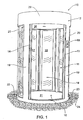
- In FIG. 1, there is shown a
security enclosure 10 of the invention, having an innermovable housing 11 and an outer fixed orstationary housing 12. The innermovable housing 11 has a pair ofentrance doors entrance 15 of theenclosure 10. There is also provided a pair ofexit doors exit 18. Theouter housing 12 hashead part 29 and has fixed pillars orcolumns 19 andwindows 20 formed from armoured glass or other transparent material. Theinner housing 11 has afloor 21. Theouter housing 12 has anannular portion 22 surroundingfloor 21, which is mounted in arecess 23 formed in aconcrete base 24. Reference is also made toceiling 35. - In FIG. 2 there is shown a schematic of the
security enclosure 10 of the invention, wherein innermovable housing 11 is suspended from acentral pin assembly 25, which is mounted tobeams head space 26 ofouter housing 12.Pin assembly 25 includesupper pin 25C. Thepin assembly 25 also includes an enlargedshaft 26A, which is surrounded byspring 26B so thatinner housing 11 may move from an initial position A, shown in phantom, when theinner housing 11 is unoccupied, to a position B when theinner housing 11 is occupied by a single person and vice versa.Spring 26B provides one form of biasing means in accordance with the invention. There is also provided additionalupper guide pins springs springs pins apertures beam 25B. A more detailed view of thepin assembly 25 is shown in FIG. 6. There is also providedlower guide pins apertures base 24. - Movement of
pins mating housing pins mating housing inner housing 11 is shown by arrows in bold outline and movement ofdoors - In the
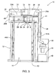
security enclosure 10 in FIG. 3, thehead part 26 includes anupper chamber 29A, which includes drug detection and/or explosive detection apparatus as hereinafter described and alower chamber 29B, which includespin assembly 25 shown in FIG. 2. There is also shown anITMS detector 30,sample desorber 31,trap 32,exhaust funnel 33, arubber seal 34 for attachment offunnel 33 toceiling 35, aring 36 for attachment of therubber seal 34 toceiling 35 andsupport frame 37 for attachment ofrubber seal 34 toexhaust funnel 33. There is also provided aflexible exhaust tube 38, which interconnectschamber 29A to pump 39. There is also provided acasing 41 fortube 38 and acabinet 42 forhousing pump 39 andcompressor 40. There is also shownmuffler 41A for reduction of air exhaust noise. There is also providedapertures 43 for insertion of nozzles (not shown) for supply of compressed air fromcompressor 40 to the interior ofinner housing 11. There is also providedsolenoid 44. There is also provided a manifold ortube 44A for connecting each ofapertures 43. There is also shown muffer 41A for reduction of air flow noise. - In FIG. 4 there is shown a detailed view of the area marked "X" in FIG. 3, which more clearly shows
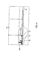
components rubber seal 34 is flexible so as to allow for movement ofpin assembly 25 andmovable component 11 relative to fixedcomponent 12. Exhaust funnel orsuction funnel 33 is also fixed relative to pinassembly 25. There is also shownfastener 36A. - In FIG. 5 there is shown
pin assembly 25, which is supported bysupport beams inner housing 11, as shown in FIG. 2.Pin assembly 25 includes ahead part 55 attached to screw threadedbolt 56 bynut 57.Head part 55 abutsweb 59 ofbeam 47.Beam 25A is welded or otherwise attached tobeam 47.Bolt 56 also hasnut 58 abutting web orplate 60 ofsupport beam 53. Thebolt 56 extends throughaperture 61 ofbeam 47 as shown.Bolt 56 extends throughinner passage 62 oflower beam 53 and throughapertures Beam 53 is welded or otherwise attached tobeam 25B. There is also illustrated fourweight sensors -
Pin assembly 25 then comprises anenlarged shaft 26A, which is surrounded by aspring 26B engaged in a retaininggroove 67 inshaft 26A. It will be noted thatceiling panel 35 may move being part ofinner housing 11 by virtue of being suspended fromspring 26B fromfree end 70.Free end 70 is attached to plate 71. There is also providedlinkage arms assembly 72. - In FIG. 6 is shown a more detailed view of the embodiment when the sensing means is a load cell. A suitable load cell is identified by the trade mark GEFRAN, which is well known in the art.
Load cell 36 is shown attached tobeam 25A bybolts 37 and associated nuts 37A.Pin 56A extends through aninternal passage 57A incantilever arm 36 and throughaperture 61 inflange 61A ofbeam 25A.Pin 56A is attached tocantilever arm 36 bynut 57B andwasher 57C.Pin 56A is attached tobeam 53A byattachment nut 58. There is provided anenlarged part 26C ofpin 56A which engages with bearingassembly 72,plate 71,panel 35 andlinkage arms spring 26B has been omitted and pin 56A andenlarged extension 26C constitutingpin assembly 25 are supported byload cell 34. - In FIG. 7, the operation of
door 13 is shown for example wheredoor 13 may be moved by pivotal movement oflinkage arm 68 about bearing 72.Door 13 is attached tolinkage arm 68 byattachment arm 73, which extends through opening 74 inpanel 35. There is also provided abottom bracket 75, which attachesdoor 13 tofloor 21. There is also provided apivot arm 76, which is attached tobracket 75 at 77 and also attached tocentral bearing 78, so thatarms door 13 when subject to appropriate drive means (not shown). - In FIG. 8, there is sown another embodiment of the mounting for
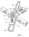
load cell 34.Beam 47A may be attached or welded tobeam 25A.Beam 48A engages withpin assembly 25 as shown. - In operation of the
security enclosure 10 of the invention, a person having already his biometric characteristics such as a finger print registered in a central database at a reception location and optionally also having his weight registered, then proceeds tosecurity enclosure 10, which has a radar sensor (not shown) located above each ofentrance 15 andexit 18.Intercom 69 is also shown. It will be appreciated in this context thatsecurity enclosure 10 is bi-directional and thusentrance 15 can form an exit andexit 18 can form an entrance if desired. - After the
door entrance 10 automatically open to allow access to the person by the radar sensor, the doors close and the person's weight is measured by the movement ofinner enclosure 11 relative toouter enclosure 12. In this regard it will be appreciated thatshaft 26A may be provided with a plurality of spaced load orweight sensors structure surrounding shaft 26A (not illustrated). On the other hand, when a load cell is used, only a single sensor is used which is located within theload cell 34. In this situation,sensors - After the correct weight is registered, then the person may place his finger on a biometric sensor inside
inner housing 11 and if his biometric data is recognised by the central database, he is simultaneously checked for the possession of any drugs or explosives. If no drugs or explosives are detected and entrance to the facility is authorised by the biometric database and he is under the prescribed weight, then theexit doors 18 will then open and allow access to the facility guarded bysecurity enclosure 10. - In the electronic circuitry which is associated with
security enclosure 10 there may be provided four contacts in a series arrangement, which will stay closed if the user passes through all security checks involving use of the (a) radar sensor; (b) weight sensor; (c) biometric sensor; and (d) drugs or explosives sensor. There also may be (e) a metal detector; and (f) an electronic detector to detect electronic chips, such as a SIMCARD in a mobile or cell phone. If any of these security checks failed, then the person is directed to return to the reception location by a voice synthesizer. Usually the whole operation may take from 14-15 seconds and more preferably 30 seconds. If this predetermined time limit is exceeded, then the person is directed to return to the reception location. Suitably each of the sensors (a), (b), (c), (d), (e) and (f) are electrically connected to a pressure switch (not shown), which is responsible for openingdoors - The
security enclosure 10 is subject to a control computer with operational software, which is used to start the cycle of operation automatically. In normal operating conditions, i.e. self management mode, the constant presence of an operator is not required. - There is provided an interphone receiver, which enables communication between the console operator and the user inside or outside the
security enclosure 10. The control console can operate the interphone, provide access to the interior by opening of the doors, provide self management mode or automatic operation, provide bi-directional operation, exit only or entrance only operation and operate the voice synthesizer. - It also will be appreciated that the security enclosure may be constructed as a single unit and can be mounted directly to a concrete floor. The security enclosure may also be used as an elevator in an elevator shaft.
- It further will be appreciated that the security enclosure may have any particular cross sectional shape and thus square, rectangular or polygonal. In such case there is no requirement for the doors to be moved in an arcuate path as shown in the preferred embodiment in the drawings.
- It will be appreciated from the foregoing that the term "sensing means" includes within its scope fractional movement of
spring 26A constituting one form of sensing means or, alternatively, refers to electronic sensing of the weight experienced bycomponent 11, whereinarm 36 has minimal or no physical movement relative toouter component 12. In this situation,sensor 34 will sense when the weight or load imparted tocomponent 11 has been exceeded by or equals a predetermined value. This will prevent opening ofexit 18. - It will be appreciated that the security enclosure of the invention makes it possible to provide a number of security checks simultaneously before providing access to a facility and thus has clear advantages over the prior art.
- The invention also includes within its scope a method for providing access to a facility, which includes the steps of:
- (i) opening an entrance to a security enclosure to a single person to gain entry to the security enclosure; and
- (ii) opening an exit of the security enclosure when the weight of said single person is under or at a predetermined value.
-
Claims (19)
- A security enclosure for guarding access to a facility, said security enclosure having an inner component supported by an outer component by support means associated with sensing means whereby, when a load is imparted to the sensing means by a person gaining entry to the inner component, access to the facility will be provided when said load is under or is equal to a prescribed value.
- A security enclosure as claimed in claim 1, wherein the support means is a pin assembly interconnecting the inner component and the outer component.
- A security enclosure as claimed in claim 1 or 2, wherein said sensing means comprises biasing means, wherein said inner component is movable relative to the outer component.
- A security enclosure as claimed in any preceding claim, wherein said load corresponds to a value which corresponds to the weight of a single person or is under said weight.
- A security enclosure as claimed in claim 1, 3 or 4, wherein said sensing means is a load cell fixedly attached to the outer component.
- A security enclosure as claimed in any one of claims 2, 4 or 5, wherein said pin assembly interconnects the load cell and said inner component.
- A security enclosure as claimed in claim 6, wherein said load cell is supported by an overhead beam of the fixed component and said pin assembly extends through an aperture of the overhead beam.
- A security enclosure as claimed in claim 7, wherein said pin assembly extends through an aperture of a lower beam located below said overhead beam, whereby said lower beam supports said inner component.
- A security enclosure as claimed in claim 2, wherein said biasing means is a coil spring having part thereof connected to the pin assembly and another part fixed to the movable component.
- A security enclosure as claimed in claim 9, wherein the pin assembly is attached to an overhead beam of the fixed component.
- A security enclosure as claimed in claim 10, wherein said pin assembly is also attached to and extends through an aperture of a lower beam of the movable component.
- A security enclosure as claimed in any preceding claim having an entrance door and an exit door, wherein said entrance door opens automatically and said exit door opens when actuated by a signal generated by the sensing means responsive to said load being under or equal to the prescribed value.
- A security enclosure as claimed in claim 12, wherein said entrance door and/or said exit door is attached to a linkage member pivotally attached to a bearing attached to said fixed component, whereby said entrance door and/or said exit door moves from a closing position to an open position, or vice versa, upon movement of said linkage member.
- A security enclosure as claimed in claim 13, wherein said linkage member comprises an upper linkage member and there is also provided a lower linkage member pivotally attached to a lower bearing of the fixed component and said entrance door and/or said exit door, wherein said lower linkage member moves in unison with the upper linkage member.
- A security enclosure as claimed in any preceding claim, wherein said fixed component includes a plurality of sensors including (a) a radar sensor; (b) a weight sensor; (c) a biometric sensor; and (d) a drugs or explosives sensor, which may be actuated upon actuation of said sensing means.
- A security enclosure as claimed in claim 15, wherein there are provided additional sensors comprising a metal detector and an electronic sensor to detect electronic chips.
- A security enclosure as claimed in claim 3 or 9, wherein there are provided a plurality of weight sensors in a mounting interconnecting the movable component and the fixed component.
- A method for providing access to a facility, which includes the steps of:(i) opening an entrance to a security enclosure to a single person to gain entry to the security enclosure; and(ii) opening an exit of the security enclosure when the weight of said single person is under or at a predetermined value.
- A method as claimed in claim 18, wherein said exit is opened only when said person has been subjected to one or more of biometric sensor, metal detector, radar sensor, drugs or explosives sensor and an electronic detector to detect electronic chips.
Applications Claiming Priority (2)
| Application Number | Priority Date | Filing Date | Title |
|---|---|---|---|
| AUPR488101 | 2001-05-09 | ||
| AUPR4881A AUPR488101A0 (en) | 2001-05-09 | 2001-05-09 | Security access enclosure |
Publications (1)
| Publication Number | Publication Date |
|---|---|
| EP1256908A1 true EP1256908A1 (en) | 2002-11-13 |
Family
ID=3828868
Family Applications (1)
| Application Number | Title | Priority Date | Filing Date |
|---|---|---|---|
| EP02076796A Withdrawn EP1256908A1 (en) | 2001-05-09 | 2002-05-07 | Security access enclosure |
Country Status (2)
| Country | Link |
|---|---|
| EP (1) | EP1256908A1 (en) |
| AU (1) | AUPR488101A0 (en) |
Cited By (4)
| Publication number | Priority date | Publication date | Assignee | Title |
|---|---|---|---|---|
| EP1583043A3 (en) * | 2004-03-30 | 2006-03-22 | Rafael Armament Development Authority Ltd. | Monitoring access via a passage |
| US9607189B2 (en) | 2015-01-14 | 2017-03-28 | Tactilis Sdn Bhd | Smart card system comprising a card and a carrier |
| US10037528B2 (en) | 2015-01-14 | 2018-07-31 | Tactilis Sdn Bhd | Biometric device utilizing finger sequence for authentication |
| US10395227B2 (en) | 2015-01-14 | 2019-08-27 | Tactilis Pte. Limited | System and method for reconciling electronic transaction records for enhanced security |
Citations (4)
| Publication number | Priority date | Publication date | Assignee | Title |
|---|---|---|---|---|
| DE3233843C1 (en) * | 1982-09-11 | 1984-01-05 | Eugen Gallenschütz Metallbau KG, 7580 Bühl | Security manway |
| EP0249421A2 (en) * | 1986-06-06 | 1987-12-16 | J.E. Johnson & Sons (Engineers) Ltd. | Security door |
| US4987767A (en) * | 1989-06-09 | 1991-01-29 | Research Corporation Technologies, Inc. | Exposive detection screening system |
| GB2349728A (en) * | 1999-03-04 | 2000-11-08 | Alessandro Manneschi | Identifying process and access booth |
-
2001
- 2001-05-09 AU AUPR4881A patent/AUPR488101A0/en not_active Abandoned
-
2002
- 2002-05-07 EP EP02076796A patent/EP1256908A1/en not_active Withdrawn
Patent Citations (4)
| Publication number | Priority date | Publication date | Assignee | Title |
|---|---|---|---|---|
| DE3233843C1 (en) * | 1982-09-11 | 1984-01-05 | Eugen Gallenschütz Metallbau KG, 7580 Bühl | Security manway |
| EP0249421A2 (en) * | 1986-06-06 | 1987-12-16 | J.E. Johnson & Sons (Engineers) Ltd. | Security door |
| US4987767A (en) * | 1989-06-09 | 1991-01-29 | Research Corporation Technologies, Inc. | Exposive detection screening system |
| GB2349728A (en) * | 1999-03-04 | 2000-11-08 | Alessandro Manneschi | Identifying process and access booth |
Cited By (9)
| Publication number | Priority date | Publication date | Assignee | Title |
|---|---|---|---|---|
| EP1583043A3 (en) * | 2004-03-30 | 2006-03-22 | Rafael Armament Development Authority Ltd. | Monitoring access via a passage |
| US7091856B2 (en) | 2004-03-30 | 2006-08-15 | Rafael Armament Development Authority, Ltd. | Monitoring access via a passage |
| US9607189B2 (en) | 2015-01-14 | 2017-03-28 | Tactilis Sdn Bhd | Smart card system comprising a card and a carrier |
| US10037528B2 (en) | 2015-01-14 | 2018-07-31 | Tactilis Sdn Bhd | Biometric device utilizing finger sequence for authentication |
| US10147091B2 (en) | 2015-01-14 | 2018-12-04 | Tactilis Sdn Bhd | Smart card systems and methods utilizing multiple ATR messages |
| US10223555B2 (en) | 2015-01-14 | 2019-03-05 | Tactilis Pte. Limited | Smart card systems comprising a card and a carrier |
| US10229408B2 (en) | 2015-01-14 | 2019-03-12 | Tactilis Pte. Limited | System and method for selectively initiating biometric authentication for enhanced security of access control transactions |
| US10275768B2 (en) | 2015-01-14 | 2019-04-30 | Tactilis Pte. Limited | System and method for selectively initiating biometric authentication for enhanced security of financial transactions |
| US10395227B2 (en) | 2015-01-14 | 2019-08-27 | Tactilis Pte. Limited | System and method for reconciling electronic transaction records for enhanced security |
Also Published As
| Publication number | Publication date |
|---|---|
| AUPR488101A0 (en) | 2001-05-31 |
Similar Documents
| Publication | Publication Date | Title |
|---|---|---|
| US6472984B1 (en) | Security entrance system | |
| EP1996466B1 (en) | Integrated verification and screening system | |
| AU2006244548B2 (en) | Passively shielded inductive sensor system for personnel screening | |
| US5915268A (en) | Vertical flow chemical detection portal | |
| US6724304B2 (en) | Security entrance system | |
| US20060081073A1 (en) | Multi-zonal detection of explosives, narcotics, and other chemical substances | |
| US6697104B1 (en) | Video based system and method for detecting and counting persons traversing an area being monitored | |
| US7382895B2 (en) | Tailgating and reverse entry detection, alarm, recording and prevention using machine vision | |
| CN1993269B (en) | Transportable control station for controlling people and luggage | |
| US8424365B2 (en) | Screening system and method for operating the same | |
| US8129691B2 (en) | Security inspection door | |
| US20040222790A1 (en) | Method and apparatus for threat screening of step-on and laid-on items | |
| EP2224268A2 (en) | Screening system and method | |
| US8473240B2 (en) | System and process for controlling a person | |
| AU2007234489A1 (en) | Apparatus and method for detecting metallic objects in shoes | |
| US20210108459A1 (en) | Threat Detection and Security Entryway System | |
| EP1256908A1 (en) | Security access enclosure | |
| AU784438B2 (en) | Security access enclosure | |
| WO2008097335A2 (en) | Passenger screening system and method | |
| US20120103061A1 (en) | Transportable portal for detection of illicit substances | |
| RU111939U1 (en) | AIRPORT SECURITY SYSTEM | |
| US9508536B2 (en) | Chemical sampling and detection methods and apparatus | |
| US20100123571A1 (en) | Inspection system and method | |
| WO2012107900A1 (en) | Security barrier for the controlled transit of people, animals and items, particularly for the exit from tourist ports and airports | |
| US20060273897A1 (en) | Dynamic software system for a security checkpoint |
Legal Events
| Date | Code | Title | Description |
|---|---|---|---|
| PUAI | Public reference made under article 153(3) epc to a published international application that has entered the european phase |
Free format text: ORIGINAL CODE: 0009012 |
|
| AK | Designated contracting states |
Kind code of ref document: A1 Designated state(s): AT BE CH CY DE DK ES FI FR GB GR IE IT LI LU MC NL PT SE TR |
|
| AX | Request for extension of the european patent |
Free format text: AL;LT;LV;MK;RO;SI |
|
| 17P | Request for examination filed |
Effective date: 20030502 |
|
| AKX | Designation fees paid |
Designated state(s): AT BE CH CY DE DK ES FI FR GB GR IE IT LI LU MC NL PT SE TR |
|
| 17Q | First examination report despatched |
Effective date: 20040319 |
|
| STAA | Information on the status of an ep patent application or granted ep patent |
Free format text: STATUS: THE APPLICATION IS DEEMED TO BE WITHDRAWN |
|
| 18D | Application deemed to be withdrawn |
Effective date: 20040930 |