EP1258400A2 - Collision severity determining system - Google Patents
Collision severity determining system Download PDFInfo
- Publication number
- EP1258400A2 EP1258400A2 EP02010665A EP02010665A EP1258400A2 EP 1258400 A2 EP1258400 A2 EP 1258400A2 EP 02010665 A EP02010665 A EP 02010665A EP 02010665 A EP02010665 A EP 02010665A EP 1258400 A2 EP1258400 A2 EP 1258400A2
- Authority
- EP
- European Patent Office
- Prior art keywords
- severity
- vehicle
- deceleration
- collision
- map
- Prior art date
- Legal status (The legal status is an assumption and is not a legal conclusion. Google has not performed a legal analysis and makes no representation as to the accuracy of the status listed.)
- Granted
Links
- 230000008859 change Effects 0.000 claims abstract description 44
- 230000015556 catabolic process Effects 0.000 claims abstract description 10
- 238000001514 detection method Methods 0.000 claims description 13
- 230000005540 biological transmission Effects 0.000 claims description 5
- 230000002093 peripheral effect Effects 0.000 claims description 2
- 230000004913 activation Effects 0.000 description 8
- 238000004891 communication Methods 0.000 description 4
- 238000010586 diagram Methods 0.000 description 4
- 230000005856 abnormality Effects 0.000 description 2
- 238000010276 construction Methods 0.000 description 2
- 238000010304 firing Methods 0.000 description 2
- 238000005070 sampling Methods 0.000 description 2
- 230000008054 signal transmission Effects 0.000 description 2
- 206010039203 Road traffic accident Diseases 0.000 description 1
- 230000003213 activating effect Effects 0.000 description 1
- 230000002349 favourable effect Effects 0.000 description 1
- 238000012986 modification Methods 0.000 description 1
- 230000004048 modification Effects 0.000 description 1
- 238000012544 monitoring process Methods 0.000 description 1
- 230000004044 response Effects 0.000 description 1
Images


Classifications
-
- B—PERFORMING OPERATIONS; TRANSPORTING
- B60—VEHICLES IN GENERAL
- B60R—VEHICLES, VEHICLE FITTINGS, OR VEHICLE PARTS, NOT OTHERWISE PROVIDED FOR
- B60R21/00—Arrangements or fittings on vehicles for protecting or preventing injuries to occupants or pedestrians in case of accidents or other traffic risks
- B60R21/01—Electrical circuits for triggering passive safety arrangements, e.g. airbags, safety belt tighteners, in case of vehicle accidents or impending vehicle accidents
- B60R21/013—Electrical circuits for triggering passive safety arrangements, e.g. airbags, safety belt tighteners, in case of vehicle accidents or impending vehicle accidents including means for detecting collisions, impending collisions or roll-over
- B60R21/0132—Electrical circuits for triggering passive safety arrangements, e.g. airbags, safety belt tighteners, in case of vehicle accidents or impending vehicle accidents including means for detecting collisions, impending collisions or roll-over responsive to vehicle motion parameters, e.g. to vehicle longitudinal or transversal deceleration or speed value
- B60R21/0133—Electrical circuits for triggering passive safety arrangements, e.g. airbags, safety belt tighteners, in case of vehicle accidents or impending vehicle accidents including means for detecting collisions, impending collisions or roll-over responsive to vehicle motion parameters, e.g. to vehicle longitudinal or transversal deceleration or speed value by integrating the amplitude of the input signal
-
- B—PERFORMING OPERATIONS; TRANSPORTING
- B60—VEHICLES IN GENERAL
- B60R—VEHICLES, VEHICLE FITTINGS, OR VEHICLE PARTS, NOT OTHERWISE PROVIDED FOR
- B60R21/00—Arrangements or fittings on vehicles for protecting or preventing injuries to occupants or pedestrians in case of accidents or other traffic risks
- B60R21/01—Electrical circuits for triggering passive safety arrangements, e.g. airbags, safety belt tighteners, in case of vehicle accidents or impending vehicle accidents
- B60R21/013—Electrical circuits for triggering passive safety arrangements, e.g. airbags, safety belt tighteners, in case of vehicle accidents or impending vehicle accidents including means for detecting collisions, impending collisions or roll-over
- B60R21/0132—Electrical circuits for triggering passive safety arrangements, e.g. airbags, safety belt tighteners, in case of vehicle accidents or impending vehicle accidents including means for detecting collisions, impending collisions or roll-over responsive to vehicle motion parameters, e.g. to vehicle longitudinal or transversal deceleration or speed value
-
- B—PERFORMING OPERATIONS; TRANSPORTING
- B60—VEHICLES IN GENERAL
- B60R—VEHICLES, VEHICLE FITTINGS, OR VEHICLE PARTS, NOT OTHERWISE PROVIDED FOR
- B60R21/00—Arrangements or fittings on vehicles for protecting or preventing injuries to occupants or pedestrians in case of accidents or other traffic risks
- B60R21/01—Electrical circuits for triggering passive safety arrangements, e.g. airbags, safety belt tighteners, in case of vehicle accidents or impending vehicle accidents
- B60R2021/01122—Prevention of malfunction
- B60R2021/01129—Problems or faults
- B60R2021/01136—Cut lines
-
- B—PERFORMING OPERATIONS; TRANSPORTING
- B60—VEHICLES IN GENERAL
- B60R—VEHICLES, VEHICLE FITTINGS, OR VEHICLE PARTS, NOT OTHERWISE PROVIDED FOR
- B60R21/00—Arrangements or fittings on vehicles for protecting or preventing injuries to occupants or pedestrians in case of accidents or other traffic risks
- B60R21/01—Electrical circuits for triggering passive safety arrangements, e.g. airbags, safety belt tighteners, in case of vehicle accidents or impending vehicle accidents
- B60R2021/01122—Prevention of malfunction
- B60R2021/01184—Fault detection or diagnostic circuits
-
- B—PERFORMING OPERATIONS; TRANSPORTING
- B60—VEHICLES IN GENERAL
- B60R—VEHICLES, VEHICLE FITTINGS, OR VEHICLE PARTS, NOT OTHERWISE PROVIDED FOR
- B60R21/00—Arrangements or fittings on vehicles for protecting or preventing injuries to occupants or pedestrians in case of accidents or other traffic risks
- B60R21/01—Electrical circuits for triggering passive safety arrangements, e.g. airbags, safety belt tighteners, in case of vehicle accidents or impending vehicle accidents
- B60R21/013—Electrical circuits for triggering passive safety arrangements, e.g. airbags, safety belt tighteners, in case of vehicle accidents or impending vehicle accidents including means for detecting collisions, impending collisions or roll-over
- B60R21/0132—Electrical circuits for triggering passive safety arrangements, e.g. airbags, safety belt tighteners, in case of vehicle accidents or impending vehicle accidents including means for detecting collisions, impending collisions or roll-over responsive to vehicle motion parameters, e.g. to vehicle longitudinal or transversal deceleration or speed value
- B60R2021/01322—Electrical circuits for triggering passive safety arrangements, e.g. airbags, safety belt tighteners, in case of vehicle accidents or impending vehicle accidents including means for detecting collisions, impending collisions or roll-over responsive to vehicle motion parameters, e.g. to vehicle longitudinal or transversal deceleration or speed value comprising variable thresholds, e.g. depending from other collision parameters
Definitions
- the invention relates to a collision severity determining system that operates at the time of activation of an occupant protection device, and provides a result of severity determination which can be used for adjusting, for example, the power level of deployment of the occupant protection device, such as an airbag system, thus assuring more appropriate occupant protection.
- Occupant protection devices such as airbag systems, which are installed on vehicles are known in the art.
- the timing of activation of such an occupant protection device is adjusted based on changes in the deceleration of the vehicle with time, which is detected by a deceleration sensor, or the like, incorporated in the vehicle.
- a deceleration sensor or the like, incorporated in the vehicle.
- it is important to detect collision of the vehicle with sufficiently high reliability.
- Japanese Laid-Open Patent Publication No.10-152014 discloses an activation control system which includes a floor sensor disposed substantially at the center of a vehicle chassis and a front sensor or sensors disposed in a front portion of the vehicle.
- the control system controls activation of an occupant protection device based on decelerations detected by the floor sensor and the front sensor(s).
- the occupant protection device can be appropriately activated by referring to a deceleration(s) detected by the front sensor(s), even when it is difficult to detect an impact only by means of the floor sensor.
- the severity determination can be made based on a deceleration detected by the floor sensor while referring to a deceleration(s) detected by the front sensor(s) as in the case where the activation of the occupant protection device is detected.
- the vehicle is provided with a predetermined fail-safe mode, so as to ensure appropriate occupant protection even when any problem occurs to the vehicle.
- a predetermined fail-safe mode for example, an ECU (electronic control unit) provided at a predetermined position in the vehicle monitors vehicle conditions, including those of an engine and a brake system, at regular intervals. Upon occurrence of any problem to the vehicle, the vehicle generates a certain warning or alarm, and starts operating in a predetermined fail-safe mode designed for securing the safety of the vehicle occupant.
- ECU electronic control unit
- the vehicle operates in the above-described fail-safe mode in various situations, which includes the case where a problem occurs to the front sensor or sensors.
- results of severity determination obtained with the same output value of the floor sensor may differ depending upon the deceleration(s) detected by the front sensor(s).
- Examples of problems that can occur to the front sensor include, for example, a failure of the front sensor during normal use, which is an extremely rare occasion, breakdown of the front sensor itself due to a collision of the vehicle, disconnection of a communication line or lines around the front sensor upon a vehicle collision, and so forth.
- the problems arising from these different causes make it impossible to detect a deceleration from the front sensor for use in severity determination.
- the occupant protection device may be pre-programmed to use a lower threshold value upon occurrence of a problem to the front sensor, for determining the collision severity in the fail-safe mode.
- a collision severity determining system for determining severity of a collision of a vehicle, which system includes: (a) a first deceleration detector disposed substantially in a central portion of a body of the vehicle so as to detect a vehicle deceleration in a longitudinal direction of the vehicle, (b) a second deceleration detector disposed in a front portion of the vehicle that is located ahead of the first deceleration detector, so as to detect a deceleration at the front portion in the longitudinal direction of the vehicle, (c) a velocity change amount calculating unit that calculates a velocity change amount of the vehicle by integrating the vehicle deceleration detected by the first deceleration detector with respect to time, (d) a severity determining unit storing two or more severity determination maps defined by the vehicle deceleration detected by the first deceleration detector and the velocity change amount, each of the severity determination maps representing a threshold pattern consisting of threshold values with which the vehicle decel
- the determining unit when the severity determining unit receives the problem detection signal from the problem detecting unit, the determining unit operates in a predetermined fail-safe mode for selecting an appropriate one of the two or more severity determination maps, and determines severity of the collision of the vehicle, based on the selected severity determination map.
- the problem detecting unit detects an abnormality in transmission of a signal indicative of the deceleration from the second deceleration detector, and the severity determining unit operates in the fail-safe mode to determine severity of the vehicle collision. In this manner, the collision severity can be determined in a desirable manner even when a problem has occurred to the second deceleration detector.
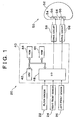
- FIG. 1 schematically illustrates a hardware configuration of a collision severity determining system 20 according to one exemplary embodiment of the invention when it is used with an occupant protection device.
- an airbag device 50 is illustrated as a typical example of the occupant protection device.
- an airbag 52 stored in the airbag device 50 is adapted to deploy at a high power level or at a low power level according to a result of determination (i.e., the severity of a collision) obtained by the severity determining system 20.
- an activation device (not shown) that determines whether the airbag device 50 should be activated. If the activation device determines the airbag device 50 should be activated, the airbag is activated to deploy at a high or low power level according to the collusion severity determined by the severity determining system 20 as described above.
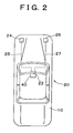
- FIG. 2 illustrates the severity determining system 20 when it is installed on a motor vehicle 10.
- FIG. 3 is a block diagram schematically illustrating a functional arrangement of the severity determining system 20.
- the severity determining system 20 of the embodiment includes a floor sensor 22 disposed in the vicinity of a console box mounted in a central portion of the vehicle 10, and a left front sensor 24 and a right front sensor 26 mounted on front portions of respective side members of the vehicle 10.
- the floor sensor 22 serves to detect a vehicle deceleration (hereinafter referred to as "floor G")
- the left and right front sensors 24, 26 serve to detect vehicle decelerations (hereinafter referred to as "front LG” and "front RG”) in the longitudinal direction (i.e., the running direction) of the vehicle 10.
- one front sensor may be disposed at the center of the front portion of the vehicle 10.
- the severity determining system 20 of the embodiment has a predetermined fail-safe mode in which collision severity is determined when the left front sensor 24 or the right front sensor 26, in particular, has any problem, such as a failure or breakdown of the sensor.
- the severity determining system 20 determines collision severity in a normal mode, as described later.
- the severity determining system 20 of the embodiment includes a microcomputer 40, which has a function of determining the severity of a collision of a vehicle based on the floor G detected by the floor sensor 22 and the front LG and RG detected by the front sensors 24 and 26.
- the microcomputer 40 includes a CPU 42 as its central component, and further includes a ROM 44 storing operation programs, a RAM 46 capable of temporarily storing data, and an input/output (I/O) circuit 48.
- the CPU 42 is arranged to start sampling of a signal from the floor sensor 22 at a predetermined frequency (e.g., 2kHz) after the floor sensor 22 detects a predetermined value of the floor G. Then, when at least one of the front LG and RG, detected by the front sensors 24 and 26, becomes greater than a predetermined threshold value, the microcomputer 40 senses a possibility of a vehicle collision, and proceeds to perform a predetermined control operation. Furthermore, the microcomputer 40 determines whether a vehicle collision is occurring (i.e., the vehicle is in collision with an object) based on the front LG and RG detected by the front sensors 24 and 26, and determines the collision severity based on the floor G detected by the floor sensor 22 while referring to the detected front LG and RG. A functional arrangement of the microcomputer 40 will be apparent from the functional block diagram of FIG. 3 showing the severity determining system 20.
- a predetermined frequency e.g., 2kHz
- a determining unit 30 of the system 20 receives, via a signal input unit 28, a signal indicative of the floor G detected by the floor sensor 22 and signals indicative of the front LG and RG detected by the front sensors 24 and 26, at a predetermined sampling frequency.
- the determination unit 30 includes a velocity change amount calculating unit 32 for calculating a velocity change amount VG which is obtained by integrating the floor G with respect to time, and a severity determining unit 36 that determines collision severity according to the floor G and velocity change amount VG in the event of a collision.
- the velocity change amount calculating unit 32 calculates the velocity change amount VG associated with the floor G, according to an expression (1) shown below.
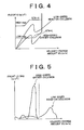
- the severity determining unit 36 incorporates a severity determination map as shown in FIG. 4, in which the vertical axis represents the floor G and the horizontal axis represents the velocity change amount VG. Using this severity determination map, the severity determining unit 36 determines collision severity based on the floor G detected by the floor sensor 22. Then, the power level of the airbag device 50 for inflating the airbag 52 is determined based on the result of severity determination.
- the severity determination map as shown in FIG. 4 includes two different threshold patterns STH-H and STH-L which will be explained below.
- Each threshold pattern STH-H, STH-L represents thresholds or reference values for determining whether the collision severity is at a high level or at a low level. Namely, the severity is determined as being at a high level (i.e., high severity) if a point determined by the floor G and the velocity change amount VG is located above the selected threshold pattern, and is determined as being at a low level (i.e., low severity) if a point determined by the floor G and the velocity change amount VG is located below the selected threshold pattern.
- the severity may be determined as HIGH, which requires the airbag 52 to deploy at a high power level, or may be determined as LOW, which requires the airbag 52 to deploy at a low power level, depending upon the mode of the vehicle collision.
- the severity determination map used in the embodiment includes a HIGH map in which the threshold values STH are set relatively high (pattern STH-H), and a LOW map in which the threshold values STH are set relatively low (pattern STH-L).
- pattern STH-H HIGH map in which the threshold values STH are set relatively high
- pattern STH-L LOW map in which the threshold values STH are set relatively low
- the collision severity be likely to be determined as being LOW, and therefore the HIGH map is used for the severity determination.
- the determination as to whether the LOW map or HIGH map is used is made according to the mode of the vehicle collision, referring to the front LG and RG detected by the front sensors 24, 26.
- the threshold pattern STH-H in the HIGH map and the threshold pattern STH-L in the LOW map are respectively predetermined for each vehicle model, based on data obtained in collision tests, virtual simulations, and the like.
- the collision severity can be determined with reference to the detected front LG, RG.
- the detection signals are not transmitted from the front sensors 24, 26 because of a certain problem or abnormality.
- the severity determining system 20 of the embodiment has a function of performing severity determination even in the case where no detection signal is transmitted from the front sensors 24, 26.
- the determining unit 30 of the severity determining system 20 includes a problem detecting unit 34.
- the problem detecting unit 34 monitors the front LG and RG transmitted from the front sensors 24 and 26 at certain intervals, and determines occurrence of a problem when no signal indicative of the front LG and RG is detected.
- the "problem" is to be interpreted to include, for example, the cases where the front sensor(s) 24, 26 fails during normal use, which is an extremely rare occasion, where the front sensor(s) 24 and 26 is/are broken down due to a collision of the vehicle, and where a communication cable or cables leading to the signal input unit 28 is/are disconnected.
- the problem detecting unit 34 recognizes the type of the problem as described above, and sends a problem detection signal that includes the type of the problem thus recognized, to the severity determining unit 36.
- a predetermined fail-safe mode is set in advance in the severity determining unit 36, and is implemented when the unit 36 receives a problem detection signal from the problem detecting unit 34.
- the severity determination is made depending upon the type of the problem of the front sensor(s) 24, 26 included in the problem detection signal from the problem detecting unit 34.
- the LOW map as shown in FIG. 4 is used for determining the collision severity.
- the severity determining unit 36 selects one of the LOW map and the HIGH map, based on the velocity change amount VG measured a predetermined time Tm after no signal indicative of the front LG and RG is detected, and determine the collision severity with reference to the selected map.
- a failure of the front sensor(s) 24, 26, which is an extremely rare case, can be recognized or confirmed by the problem detecting unit 34 which regularly monitors output signals from the front sensors 24 and 26.
- the problem detecting unit 34 which regularly monitors output signals from the front sensors 24 and 26.
- a failure of the front sensor(s) 24, 26 is detected, a certain warning may be given to the occupant by means of an alert lamp or the like so that the occupant will have the vehicle repaired immediately, thus eliminating the problem of the failure of the front sensor(s) 24, 26.
- the vehicle runs into a traffic accident before the front sensors 24, 26 are repaired.
- it is desirable to set the severity determination mode so that the airbag system 50 can deal with a high-speed collision, or the like, that causes a great impact to the occupant.
- the severity determining unit 36 selects the LOW map for determining the collision severity.
- FIG. 5 shows data detected in the case (high-speed OBD) where the vehicle undergoes a high-speed offset collision with a relatively soft obstacle, and the case where the vehicle undergoes a low-speed head-on collision.
- the front LG (or RG) reaches a peak when the velocity change amount VG is still small.
- the high-speed offset collision is one of collision modes in which a large impact tends to be applied to the occupant, and therefore the severity determination is made using the LOW map so that the severity is more likely to be determined as being HIGH.
- the front LG (or RG) gradually changes as the velocity change amount VG increases, and assumes a relatively high value at its peak in the later stage of the collision, though the peak value is still much lower than that of the high-speed offset collision.
- the low-speed head-on collision represented in the graph is one of collision modes in which a small impact tends to be applied to the occupant, and therefore the severity determination is made using the HIGH map so that the severity is more likely to be determined as being LOW.
- a broken line in FIG. 5 represents a boundary line based on which one of the HIGH map and the LOW map is selected.
- a collision that shows a relatively high front LG (or RG) in the initial stage of the collision (on the left-hand side of the boundary line) may be determined as a collision mode in which the severity determination is made using the LOW map so that the severity is more likely to be determined as being HIGH.
- a collision that shows a relatively high front LG (or RG) in the later stage of the collision (on the right-hand side of the boundary line) may be determined as a collision mode in which the severity determination is made using the HIGH map so that the severity is more likely to be determined as being LOW.
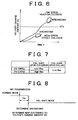
- the above-described breakdown of the front sensor(s) 24, 26 or its peripheral wiring due to a vehicle collision is supposed to occur when the front LG (RG) reaches its peak.
- the graph in FIG. 6 shows a relationship between time T measured from a point of time when the vehicle collides with an object, and the velocity change amount VG.
- the front sensor 24, 26 or the like tends to break down (become inoperative) before the velocity change amount VG increases to a certain level. In this case, therefore, the detected velocity change amount VG is kept at a relatively low value.
- the front sensor 24, 26 or the like tends to break down after the velocity change amount VG exceeds a certain level.
- the detected velocity change amount VG has a higher value than that in the case of the high-speed offset collision.
- a certain reference value KTH is set between the low value and the high value of the velocity change amount VG as described above. If the detected velocity change amount VG is larger than the reference value KTH, the collision in question is determined as one of collision modes in which the severity determination is made using the HIGH map so that the severity is more likely to be determined as being LOW. If the detected velocity change amount VG does not exceed the reference value KTH, on the other hand, the collision in question is determined as one of collision modes in which the severity determination is made using the LOW map so that the severity is more likely to be determined as being HIGH.
- the table of FIG. 7 summarizes selection of the HIGH map or the LOW map by the severity determining unit 36 in the fail-safe mode.
- the fail-safe mode may be established by mistake when the transmission of the front LG or RG is interrupted due to noise on communication lines, or other factors.
- the problem detecting unit 34 does not immediately transmit a problem detection signal indicating breakdown of the front sensor 24, 26, or the like, to the severity determining unit 36, when no signal indicative of the front LG, RG is transmitted from the front sensors 24, 26 in a normal mode, as shown in Fig. 8. Rather, the problem (i.e., no transmission of the front LG or RG) is judged as being caused by breakdown of the front sensor 24, 26 when a predetermined time Tm elapses after the transmission of the front LG or RG is stopped.
- the severity determining unit 36 is brought into the fail-safe mode upon a lapse of the predetermined time Tm.
- the severity determining unit 36 is prevented from being brought into the fail-safe mode by mistake when the transmission of the front LG or RG is temporarily stopped due to noise, or any other reason.
- the severity determining unit 36 determines which of the LOW map and the HIGH map is used, depending upon whether the velocity change amount VG detected at this time is higher or lower a reference value KTH similar to that of FIG. 6.
- the reference value KTH is predetermined for each vehicle based on data obtained in collision tests, virtual simulations, and the like.
- the severity determining system 20 operates in the fail-safe mode, and determines the collision severity with high accuracy according to the severity determination map as shown in FIG. 4, which map involves the floor G and velocity change amount VG.
- the severity determination is performed using the LOW map in the case of a high-speed offset collision (ODB) in which it is preferable to determine the severity as being HIGH.
- ODB high-speed offset collision
- the severity determination is performed using the HIGH map.
- the airbag device 50 includes an airbag 52, two inflaters 54 that supply gas to the airbag 52, two firing devices 56 which fire a gas generating agent (not shown in FIG. 1), and two drive circuits 58 that supply electric current to the respective firing devices 56 to fire the gas generating agent in response to a severity determination signal from the microcomputer 40.
- the airbag 52 can be rapidly deployed at a high power level when both of the inflaters 54 are actuated simultaneously, and can also be deployed at a low power level when the two inflaters 54 are actuated at different points of time.
- the airbag 52 is deployed at a high power level when the severity determining system 20 determines the collision severity as HIGH, and is deployed at a low power level when the severity determining system 20 determines the collision severity as LOW.
- the severity determining system 20 operates in the fail-safe mode so as to enable deployment of the airbag device 50 that is favorable or advantageous to the occupant.
- the severity determining system 20 of the embodiment constantly achieves desired occupant protection with high reliability.
- FIG. 9 shows a control routine for determining collision severity when the severity determining system 20 of the present embodiment operates in a fail-safe mode, which is established when no signal is transmitted from the front sensor 24 and/or front sensor 26.
- the severity determination routine of FIG. 9 is implemented by the microcomputer 40 as shown in FIG. 1.
- the problem detecting unit 34 determines in step S100 whether no signal indicative of the front LG or RG is transmitted from the front sensors 24, 26. If no signal transmission is detected in step S100, the problem detecting unit 34 then determines in step S102 whether the problem arises from a failure of the front sensor(s) 24, 26 or from breakdown of the front sensor(s) 24, 26, or the like, which is caused by the vehicle collision. If a failure of the front sensor(s) 24, 26 is determined in step S102, the HIGH map is used for determining collision severity in step S108, so that the severity is more likely to be determined as being LOW. After executing step S108, the routine of FIG. 9 is finished.
- step S104 is executed, assuming that a vehicle collision has occurred, to determine whether the predetermined time Tm has elapsed since the front LG or RG became unable to be detected.
- step S104 determines that the time Tm has elapsed, the vehicle is determined as being in a collision state, and step S106 is executed to determine whether the current velocity change amount VG of the vehicle is greater than the predetermined reference value KTH. If the velocity change amount VG is determined as being greater than the reference value KTH in step S106, the severity determination is performed in step S108 using the HIGH map so that the severity is more likely to be determined as LOW, and thereafter the routine is finished. Conversely, if the velocity change amount VG is determined as not greater than the reference value KTH in step S106, the severity determination is performed in step S110 using the LOW map so that the severity is likely to be determined as HIGH, and thereafter the routine is finished.
- the microcomputer 40 is adapted to perform overall control of the severity determining system 20, including control in the fail-safe mode.
- the invention is not limited to this arrangement.
- an ECU electronic control unit
- the microcomputer 40 may be constructed as a part of the ECU.
- the severity determining system 20 is applied to the airbag device 50 which is employed as the occupant protection device.
- the severity determining system of the invention may be applied to a seatbelt pretensioner system serving as an occupant protection device, which automatically takes up the seatbelt in the event of a collision.
- the severity determining device 20 may be applied to both the airbag device and the seatbelt pretensioner system.
- a collision severity determining system for determining severity of a collision of a vehicle includes a first deceleration detector disposed in a central portion of a vehicle body for detecting a vehicle deceleration in a longitudinal direction of the vehicle, and a second deceleration detector disposed in a front portion of the vehicle for detecting a deceleration in the longitudinal direction.
- a controller of the system calculates a velocity change amount of the vehicle by integrating the vehicle deceleration with respect to time, and determines severity of the vehicle collision by comparing the vehicle deceleration with a threshold value corresponding to the same velocity change amount.
- the severity determining unit When a problem, such as a failure or breakdown of the second deceleration detector, occurs, the severity determining unit operates in a predetermined fail-safe mode for selecting an appropriate one of severity determination maps stored in the controller, and makes a severity determination based on the selected severity determination map.
- a problem such as a failure or breakdown of the second deceleration detector
Abstract
Description
Selected Figure: FIG. 3
Claims (8)
- A collision severity determining system for determining severity of a collision of a vehicle, comprising:whereina first deceleration detector disposed substantially in a central portion of a body of the vehicle so as to detect a vehicle deceleration in a longitudinal direction of the vehicle;a second deceleration detector disposed in a front portion of the vehicle that is located ahead of the first deceleration detector, so as to detect a deceleration at the front portion in the longitudinal direction of the vehicle;a velocity change amount calculating unit that calculates a velocity change amount of the vehicle by integrating the vehicle deceleration detected by the first deceleration detector with respect to time;a severity determining unit storing two or more severity determination maps defined by the vehicle deceleration detected by the first deceleration detector and the velocity change amount, each of the severity determination maps representing a threshold pattern consisting of threshold values with which the vehicle deceleration is compared so as to determine severity of the collision of the vehicle; anda problem detecting unit that generates a problem detection signal that indicates that a problem has occurred to the vehicle, when detecting an absence of a signal indicative of the deceleration transmitted from the second deceleration detector,
when receiving the problem detection signal from the problem detecting unit, the severity determining unit operates in a predetermined fail-safe mode for selecting an appropriate one of the two or more severity determination maps, and determines severity of the collision of the vehicle, based on the selected severity determination map. - A severity determination system according to claim 1, wherein:when receiving no problem detection signal from the problem detecting unit, the severity determining unit determines severity of the collision of the vehicle, by using one of the two or more severity determination maps that is selected based on the deceleration detected by the second deceleration detector.
- A severity determination system according to claim 1 or 2, wherein the severity determining unit determines the severity as being at a low level when the vehicle deceleration is not greater than a corresponding threshold value on the threshold pattern of the selected severity determination map, and determines the severity as being at a high level when the vehicle deceleration is greater than a corresponding threshold value on the threshold pattern of the selected severity determination map.
- A severity determination system according to claim 3, wherein the two or more severity determination maps comprises a high map representing a first threshold pattern, and a low map representing a second threshold pattern having threshold values that are lower than those of the first threshold pattern.
- A severity determination system according to claim 4, wherein the predetermined fail-safe mode of the severity determining unit is established when a problem based on a failure of the second deceleration detector is detected, and wherein the severity determining unit makes a collision severity determination by using the low map in the case of the failure of the second deceleration detector.
- A severity determination system according to claim 4, wherein the predetermined fail-safe mode of the severity determining unit is established when a problem based on a breakdown of the second deceleration detector or a peripheral portion thereof due to the vehicle collision is detected, and wherein the severity determining unit selects one of the low map and the high map based on the velocity change amount obtained upon a lapse of a predetermined time after transmission of the signal indicative of the deceleration is stopped, and makes a collision severity determination by using the selected one of the low map and the high map.
- A severity determination system according to claim 6, wherein the severity determining unit selects the low map for use in severity determination when the velocity change amount obtained upon the lapse of the predetermined time is smaller than a predetermined reference value, and selects the high map when the velocity change amount is larger than the predetermined reference value.
- An apparatus comprising:wherein the occupant protection device is activated with one of the at least two power levels that is selected based on a result of severity determination of the collision severity determining system.an occupant protection device that protects an occupant of a vehicle against a collision, the occupant protection device having at least two power levels; anda collision severity determining system that determines severity of the collision of the vehicle, which comprises:(a) a first deceleration detector disposed substantially in a central portion of a body of the vehicle so as to detect a vehicle deceleration in a longitudinal direction of the vehicle;(b) a second deceleration detector disposed in a front portion of the vehicle that is located ahead of the first deceleration detector, so as to detect a deceleration at the front portion in the longitudinal direction of the vehicle;(c) a velocity change amount calculating unit that calculates a velocity change amount of the vehicle by integrating the vehicle deceleration detected by the first deceleration detector with respect to time;(d) a severity determining unit storing two or more severity determination maps defined by the vehicle deceleration detected by the first deceleration detector and the velocity change amount, each of the severity determination maps representing a threshold pattern consisting of threshold values with which the vehicle deceleration is compared so as to determine severity of the collision of the vehicle; and(e) a problem detecting unit that generates a problem detection signal that indicates that a problem has occurred to the vehicle, when detecting an absence of a signal indicative of the deceleration transmitted from the second deceleration detector, wherein, when receiving the problem detection signal from the problem detecting unit, the severity determining unit operates in a predetermined fail-safe mode for selecting an appropriate one of the two or more severity determination maps, and determines severity of the collision of the vehicle, based on the selected severity determination map,
Applications Claiming Priority (2)
| Application Number | Priority Date | Filing Date | Title |
|---|---|---|---|
| JP2001143669A JP3620466B2 (en) | 2001-05-14 | 2001-05-14 | Severity judgment device |
| JP2001143669 | 2001-05-14 |
Publications (3)
| Publication Number | Publication Date |
|---|---|
| EP1258400A2 true EP1258400A2 (en) | 2002-11-20 |
| EP1258400A3 EP1258400A3 (en) | 2003-01-02 |
| EP1258400B1 EP1258400B1 (en) | 2004-04-07 |
Family
ID=18989775
Family Applications (1)
| Application Number | Title | Priority Date | Filing Date |
|---|---|---|---|
| EP02010665A Expired - Lifetime EP1258400B1 (en) | 2001-05-14 | 2002-05-13 | Collision severity determining system |
Country Status (5)
| Country | Link |
|---|---|
| US (1) | US6647331B2 (en) |
| EP (1) | EP1258400B1 (en) |
| JP (1) | JP3620466B2 (en) |
| CN (1) | CN1285913C (en) |
| DE (1) | DE60200337T2 (en) |
Cited By (2)
| Publication number | Priority date | Publication date | Assignee | Title |
|---|---|---|---|---|
| WO2006106018A1 (en) * | 2005-04-06 | 2006-10-12 | Robert Bosch Gmbh | Method for generating a firing signal for occupant protection systems |
| EP2070773A1 (en) * | 2007-12-11 | 2009-06-17 | Robert Bosch Gmbh | Method and arrangement to activate passenger protection devices from a passenger protection system in a vehicle |
Families Citing this family (28)
| Publication number | Priority date | Publication date | Assignee | Title |
|---|---|---|---|---|
| US7625006B2 (en) | 2001-04-09 | 2009-12-01 | Trw Automotive U.S. Llc | Method and apparatus for controlling an actuatable restraining device using crush zone sensors for safing function |
| JP3695351B2 (en) * | 2001-05-14 | 2005-09-14 | トヨタ自動車株式会社 | Occupant protection device starter |
| JP3608052B2 (en) * | 2001-08-09 | 2005-01-05 | トヨタ自動車株式会社 | Activation control device for occupant protection device |
| DE10152749A1 (en) * | 2001-10-25 | 2003-05-08 | Bayerische Motoren Werke Ag | Method for triggering a vehicle occupant restraint |
| JP2004034828A (en) * | 2002-07-03 | 2004-02-05 | Denso Corp | Start-up system for vehicle occupant protecting device |
| DE10245781A1 (en) * | 2002-10-01 | 2004-04-15 | Robert Bosch Gmbh | Method for triggering a restraint system in a vehicle |
| US6816766B2 (en) * | 2002-11-26 | 2004-11-09 | General Motors Corporation | Continuous collision severity prediction |
| DE10317212A1 (en) * | 2003-04-15 | 2004-11-04 | Robert Bosch Gmbh | Method for monitoring the functionality of a control device and diagnostic device |
| JP4429860B2 (en) * | 2004-10-05 | 2010-03-10 | 三菱電機株式会社 | Occupant protection activation device |
| US7448251B2 (en) * | 2005-01-06 | 2008-11-11 | Honda Motor Co., Ltd. | Method for preparing a motor vehicle for a crash test |
| US7930080B2 (en) * | 2005-06-07 | 2011-04-19 | Denso Corporation | Passenger protecting apparatus and method for protecting passenger |
| JP4613741B2 (en) * | 2005-08-05 | 2011-01-19 | トヨタ自動車株式会社 | Vehicle data recording device |
| DE102005038616A1 (en) * | 2005-08-16 | 2007-02-22 | Trw Automotive Gmbh | Method for controlling an active restraint system |
| JP4706654B2 (en) * | 2007-03-27 | 2011-06-22 | トヨタ自動車株式会社 | Collision avoidance device |
| CN101674959B (en) * | 2007-05-10 | 2012-01-25 | 三菱电机株式会社 | Vehicle condition detecting unit and occupant protection apparatus including the unit |
| US8554495B2 (en) * | 2010-01-22 | 2013-10-08 | X2 Biosystems, Inc. | Head impact analysis and comparison system |
| US8725346B2 (en) * | 2010-12-15 | 2014-05-13 | Hong Kong Productivity Council | Collision severity determination system and method |
| KR101697922B1 (en) * | 2010-12-23 | 2017-01-19 | 현대모비스 주식회사 | The control method of Passenger protection device for automobile |
| EP2674341B1 (en) | 2011-02-10 | 2016-02-10 | Toyota Jidosha Kabushiki Kaisha | Hybrid vehicle and method for controlling hybrid vehicle |
| JP5778236B2 (en) * | 2013-10-18 | 2015-09-16 | 本田技研工業株式会社 | Vehicle collision determination device |
| US10599155B1 (en) | 2014-05-20 | 2020-03-24 | State Farm Mutual Automobile Insurance Company | Autonomous vehicle operation feature monitoring and evaluation of effectiveness |
| KR102186350B1 (en) * | 2014-05-30 | 2020-12-03 | 현대모비스 주식회사 | Apparatus and method for requesting emergency call about vehicle accident using driving information of vehicle |
| JP6103145B2 (en) * | 2014-06-17 | 2017-03-29 | マツダ株式会社 | Emergency call device for vehicles |
| JP2016068905A (en) * | 2014-10-01 | 2016-05-09 | トヨタ自動車株式会社 | Passenger state estimation system and on-vehicle apparatus |
| US10336321B1 (en) | 2014-11-13 | 2019-07-02 | State Farm Mutual Automobile Insurance Company | Autonomous vehicle control assessment and selection |
| JP6455721B2 (en) * | 2015-05-26 | 2019-01-23 | 株式会社デンソー | Collision detection device |
| US9870649B1 (en) | 2015-08-28 | 2018-01-16 | State Farm Mutual Automobile Insurance Company | Shared vehicle usage, monitoring and feedback |
| CN111976638B (en) * | 2020-08-28 | 2021-04-13 | 广州市网优优信息技术开发有限公司 | Vehicle collision detection method and system based on vehicle-mounted intelligent terminal |
Citations (4)
| Publication number | Priority date | Publication date | Assignee | Title |
|---|---|---|---|---|
| US5498028A (en) * | 1994-01-04 | 1996-03-12 | Trw Inc. | Method and apparatus for controlling an actuatable restraining device |
| EP0982199A1 (en) * | 1997-05-16 | 2000-03-01 | Autolive Japan Ltd. | Actuation controller for air bag device |
| US6070113A (en) * | 1996-06-21 | 2000-05-30 | Automotive Systems Laboratory, Inc. | Hybrid vehicle crash discrimination system |
| WO2002012029A1 (en) * | 2000-08-03 | 2002-02-14 | Toyota Jidosha Kabushiki Kaisha | Airbag trigger control system |
Family Cites Families (4)
| Publication number | Priority date | Publication date | Assignee | Title |
|---|---|---|---|---|
| JP3358022B2 (en) | 1997-05-16 | 2002-12-16 | オートリブ・ジャパン株式会社 | Airbag deployment control device |
| JP3333813B2 (en) | 1996-11-20 | 2002-10-15 | トヨタ自動車株式会社 | Startup control device for occupant protection device |
| US6186539B1 (en) * | 1998-07-01 | 2001-02-13 | Trw Inc. | Method and apparatus for controlling an actuatable restraint device using crash severity indexing and crush zone sensor |
| JP3487279B2 (en) | 2000-10-02 | 2004-01-13 | トヨタ自動車株式会社 | Startup control device for occupant protection device |
-
2001
- 2001-05-14 JP JP2001143669A patent/JP3620466B2/en not_active Expired - Fee Related
-
2002
- 2002-05-08 US US10/140,295 patent/US6647331B2/en not_active Expired - Fee Related
- 2002-05-13 DE DE60200337T patent/DE60200337T2/en not_active Expired - Lifetime
- 2002-05-13 CN CNB021193576A patent/CN1285913C/en not_active Expired - Fee Related
- 2002-05-13 EP EP02010665A patent/EP1258400B1/en not_active Expired - Lifetime
Patent Citations (4)
| Publication number | Priority date | Publication date | Assignee | Title |
|---|---|---|---|---|
| US5498028A (en) * | 1994-01-04 | 1996-03-12 | Trw Inc. | Method and apparatus for controlling an actuatable restraining device |
| US6070113A (en) * | 1996-06-21 | 2000-05-30 | Automotive Systems Laboratory, Inc. | Hybrid vehicle crash discrimination system |
| EP0982199A1 (en) * | 1997-05-16 | 2000-03-01 | Autolive Japan Ltd. | Actuation controller for air bag device |
| WO2002012029A1 (en) * | 2000-08-03 | 2002-02-14 | Toyota Jidosha Kabushiki Kaisha | Airbag trigger control system |
Cited By (2)
| Publication number | Priority date | Publication date | Assignee | Title |
|---|---|---|---|---|
| WO2006106018A1 (en) * | 2005-04-06 | 2006-10-12 | Robert Bosch Gmbh | Method for generating a firing signal for occupant protection systems |
| EP2070773A1 (en) * | 2007-12-11 | 2009-06-17 | Robert Bosch Gmbh | Method and arrangement to activate passenger protection devices from a passenger protection system in a vehicle |
Also Published As
| Publication number | Publication date |
|---|---|
| EP1258400B1 (en) | 2004-04-07 |
| CN1285913C (en) | 2006-11-22 |
| JP3620466B2 (en) | 2005-02-16 |
| CN1385705A (en) | 2002-12-18 |
| DE60200337T2 (en) | 2005-05-12 |
| US6647331B2 (en) | 2003-11-11 |
| US20020169535A1 (en) | 2002-11-14 |
| DE60200337D1 (en) | 2004-05-13 |
| JP2002331905A (en) | 2002-11-19 |
| EP1258400A3 (en) | 2003-01-02 |
Similar Documents
| Publication | Publication Date | Title |
|---|---|---|
| EP1258400B1 (en) | Collision severity determining system | |
| EP1028039B1 (en) | Activation control apparatus of occupant safety system with a collision identifier | |
| US6640174B2 (en) | Restraint and fuel system cutoff control module | |
| US5712784A (en) | Data transmission process within a data processing system suitable for use in motor vehicles | |
| EP1024977B1 (en) | Crash detection system | |
| CA2416422C (en) | Airbag trigger control system | |
| US7739012B2 (en) | Air bag system | |
| US6196578B1 (en) | Activation controlling apparatus for passive safety device | |
| JP2003182509A (en) | Occupant protecting system | |
| US7207410B2 (en) | Apparatus and method for enhanced impact sensing | |
| US6209910B1 (en) | Ignition control system for a passive safety device | |
| JP3632619B2 (en) | Occupant protection device starter | |
| US6906622B2 (en) | System for sensing a head-on collision in a motor vehicle | |
| US7606647B2 (en) | Communication control device for passenger protection device | |
| US7011175B2 (en) | Method of activating safety devices utility | |
| JP4203814B2 (en) | Vehicle occupant protection device | |
| US7503580B2 (en) | Vehicle occupant protection system with disable mode | |
| JP3358022B2 (en) | Airbag deployment control device | |
| US6848712B2 (en) | Method of triggering a vehicle occupant restraining device | |
| KR100603710B1 (en) | Apparatus and method for controlling fire of an air bag according to speed of the other part in a car air bag apparatus | |
| JPH1159323A (en) | Occupant crash protection device | |
| KR100496337B1 (en) | A Airbag Control Method of Vehicle | |
| JP2004284422A (en) | Occupant crash protection device | |
| KR100201469B1 (en) | A releasing method of a safety apparatus for an automobile | |
| KR20060084914A (en) | Air-bag's control method |
Legal Events
| Date | Code | Title | Description |
|---|---|---|---|
| PUAI | Public reference made under article 153(3) epc to a published international application that has entered the european phase |
Free format text: ORIGINAL CODE: 0009012 |
|
| PUAL | Search report despatched |
Free format text: ORIGINAL CODE: 0009013 |
|
| 17P | Request for examination filed |
Effective date: 20020513 |
|
| AK | Designated contracting states |
Kind code of ref document: A2 Designated state(s): AT BE CH CY DE DK ES FI FR GB GR IE IT LI LU MC NL PT SE TR |
|
| AX | Request for extension of the european patent |
Free format text: AL;LT;LV;MK;RO;SI |
|
| AK | Designated contracting states |
Kind code of ref document: A3 Designated state(s): AT BE CH CY DE DK ES FI FR GB GR IE IT LI LU MC NL PT SE TR |
|
| AX | Request for extension of the european patent |
Free format text: AL;LT;LV;MK;RO;SI |
|
| 17Q | First examination report despatched |
Effective date: 20030514 |
|
| GRAP | Despatch of communication of intention to grant a patent |
Free format text: ORIGINAL CODE: EPIDOSNIGR1 |
|
| AKX | Designation fees paid |
Designated state(s): DE FR GB |
|
| GRAS | Grant fee paid |
Free format text: ORIGINAL CODE: EPIDOSNIGR3 |
|
| GRAA | (expected) grant |
Free format text: ORIGINAL CODE: 0009210 |
|
| AK | Designated contracting states |
Kind code of ref document: B1 Designated state(s): DE FR GB |
|
| REG | Reference to a national code |
Ref country code: GB Ref legal event code: FG4D |
|
| REF | Corresponds to: |
Ref document number: 60200337 Country of ref document: DE Date of ref document: 20040513 Kind code of ref document: P |
|
| REG | Reference to a national code |
Ref country code: IE Ref legal event code: FG4D |
|
| ET | Fr: translation filed | ||
| REG | Reference to a national code |
Ref country code: IE Ref legal event code: MM4A |
|
| PLBE | No opposition filed within time limit |
Free format text: ORIGINAL CODE: 0009261 |
|
| STAA | Information on the status of an ep patent application or granted ep patent |
Free format text: STATUS: NO OPPOSITION FILED WITHIN TIME LIMIT |
|
| 26N | No opposition filed |
Effective date: 20050110 |
|
| REG | Reference to a national code |
Ref country code: GB Ref legal event code: 746 Effective date: 20130215 |
|
| REG | Reference to a national code |
Ref country code: DE Ref legal event code: R084 Ref document number: 60200337 Country of ref document: DE Effective date: 20130312 |
|
| PGFP | Annual fee paid to national office [announced via postgrant information from national office to epo] |
Ref country code: DE Payment date: 20130515 Year of fee payment: 12 Ref country code: GB Payment date: 20130508 Year of fee payment: 12 |
|
| PGFP | Annual fee paid to national office [announced via postgrant information from national office to epo] |
Ref country code: FR Payment date: 20130531 Year of fee payment: 12 |
|
| REG | Reference to a national code |
Ref country code: DE Ref legal event code: R119 Ref document number: 60200337 Country of ref document: DE |
|
| GBPC | Gb: european patent ceased through non-payment of renewal fee |
Effective date: 20140513 |
|
| REG | Reference to a national code |
Ref country code: DE Ref legal event code: R119 Ref document number: 60200337 Country of ref document: DE Effective date: 20141202 |
|
| REG | Reference to a national code |
Ref country code: FR Ref legal event code: ST Effective date: 20150130 |
|
| PG25 | Lapsed in a contracting state [announced via postgrant information from national office to epo] |
Ref country code: DE Free format text: LAPSE BECAUSE OF NON-PAYMENT OF DUE FEES Effective date: 20141202 |
|
| PG25 | Lapsed in a contracting state [announced via postgrant information from national office to epo] |
Ref country code: FR Free format text: LAPSE BECAUSE OF NON-PAYMENT OF DUE FEES Effective date: 20140602 Ref country code: GB Free format text: LAPSE BECAUSE OF NON-PAYMENT OF DUE FEES Effective date: 20140513 |