EP1259048A2 - Input device connected to mobile communication terminal with which characters can be input easily - Google Patents
Input device connected to mobile communication terminal with which characters can be input easily Download PDFInfo
- Publication number
- EP1259048A2 EP1259048A2 EP02253161A EP02253161A EP1259048A2 EP 1259048 A2 EP1259048 A2 EP 1259048A2 EP 02253161 A EP02253161 A EP 02253161A EP 02253161 A EP02253161 A EP 02253161A EP 1259048 A2 EP1259048 A2 EP 1259048A2
- Authority
- EP
- European Patent Office
- Prior art keywords
- unit
- operating
- operating unit
- mobile terminal
- input device
- Prior art date
- Legal status (The legal status is an assumption and is not a legal conclusion. Google has not performed a legal analysis and makes no representation as to the accuracy of the status listed.)
- Withdrawn
Links
Images


Classifications
-
- H—ELECTRICITY
- H04—ELECTRIC COMMUNICATION TECHNIQUE
- H04M—TELEPHONIC COMMUNICATION
- H04M1/00—Substation equipment, e.g. for use by subscribers
- H04M1/02—Constructional features of telephone sets
- H04M1/0202—Portable telephone sets, e.g. cordless phones, mobile phones or bar type handsets
- H04M1/0206—Portable telephones comprising a plurality of mechanically joined movable body parts, e.g. hinged housings
- H04M1/0208—Portable telephones comprising a plurality of mechanically joined movable body parts, e.g. hinged housings characterized by the relative motions of the body parts
- H04M1/0214—Foldable telephones, i.e. with body parts pivoting to an open position around an axis parallel to the plane they define in closed position
- H04M1/0216—Foldable in one direction, i.e. using a one degree of freedom hinge
-
- G—PHYSICS
- G06—COMPUTING; CALCULATING OR COUNTING
- G06F—ELECTRIC DIGITAL DATA PROCESSING
- G06F1/00—Details not covered by groups G06F3/00 - G06F13/00 and G06F21/00
- G06F1/16—Constructional details or arrangements
- G06F1/1613—Constructional details or arrangements for portable computers
- G06F1/1615—Constructional details or arrangements for portable computers with several enclosures having relative motions, each enclosure supporting at least one I/O or computing function
- G06F1/1616—Constructional details or arrangements for portable computers with several enclosures having relative motions, each enclosure supporting at least one I/O or computing function with folding flat displays, e.g. laptop computers or notebooks having a clamshell configuration, with body parts pivoting to an open position around an axis parallel to the plane they define in closed position
-
- G—PHYSICS
- G06—COMPUTING; CALCULATING OR COUNTING
- G06F—ELECTRIC DIGITAL DATA PROCESSING
- G06F1/00—Details not covered by groups G06F3/00 - G06F13/00 and G06F21/00
- G06F1/16—Constructional details or arrangements
- G06F1/1613—Constructional details or arrangements for portable computers
- G06F1/1626—Constructional details or arrangements for portable computers with a single-body enclosure integrating a flat display, e.g. Personal Digital Assistants [PDAs]
-
- G—PHYSICS
- G06—COMPUTING; CALCULATING OR COUNTING
- G06F—ELECTRIC DIGITAL DATA PROCESSING
- G06F1/00—Details not covered by groups G06F3/00 - G06F13/00 and G06F21/00
- G06F1/16—Constructional details or arrangements
- G06F1/1613—Constructional details or arrangements for portable computers
- G06F1/1632—External expansion units, e.g. docking stations
-
- H—ELECTRICITY
- H04—ELECTRIC COMMUNICATION TECHNIQUE
- H04M—TELEPHONIC COMMUNICATION
- H04M2250/00—Details of telephonic subscriber devices
- H04M2250/70—Details of telephonic subscriber devices methods for entering alphabetical characters, e.g. multi-tap or dictionary disambiguation
Definitions
- the present invention relates to an input device which is connected to a mobile communication terminal such as a mobile phone and with which characters can be input easily.
- characters are usually input by the following methods.
- characters are input by using a numeric keypad (a group of keys including number keys and keys for the four basic operators).
- Japanese characters for example, are input in the form of kana characters (Japanese syllabic alphabet, and there are two types: hiragana and katakana) or romaji (writing system based on Roman characters used to represent Japanese text).
- kana characters Japanese syllabic alphabet, and there are two types: hiragana and katakana
- romaji writing system based on Roman characters used to represent Japanese text.
- characters are input by writing each character on a liquid crystal display with a pen-type input device.
- keyboard-type input devices with a plurality of keys arranged thereon are sold separately, and are used for inputting characters by connecting them to the mobile terminals.
- Fig. 6 is a perspective view of a known keyboard-type input device and a mobile terminal to which the keyboard-type input device is connected.
- an input device 50 includes an operating unit 51 provided with a plurality of operation keys 52 and a connecting cable 53 which extends from the operating unit 51.
- the connecting cable 53 is provided with a connecter 54 at the distal end thereof, and the connecter 54 is attached to a connecting port 61 formed at the bottom end of a mobile terminal 60 in a detachable manner.
- the mobile terminal 60 includes an input unit 62 and a display unit 63.
- kana characters and romaji can be input by operating the operation keys 52.
- operating data is transmitted to the mobile terminal 60, and character strings are displayed on the display unit 63. Then, the character strings are converted into transmission data, which is transmitted from the mobile terminal 60 to other mobile terminals.
- the operation to connect and disconnect the input device 50 to/from the mobile terminal is cumbersome.
- the input device 50 and the mobile terminal 60 are connected to each other with the connecting cable, the user cannot input characters easily and smoothly while holding both the input device 50 and the mobile terminal 60.
- the input device 50 since the input device 50 must be disconnected from the mobile terminal 60 and carried separately when it is not being used, the input device 50 is not carried conveniently.
- an object of the present invention is to provide an input device with which characters can be input quickly and reliably and which can be carried conveniently.
- An input device of includes a supporting unit including a connector which is detachably connected to a mobile terminal having a display unit; an operating unit which transmits an operation signal to the mobile terminal via the connector; a plurality of operation keys provided on an operating surface of the operating unit; and a position converting unit which is formed between the supporting unit and the operating unit, and which, while the connector is connected to the mobile terminal, allows the operating unit to rotate between a stored position at which the operating unit is hidden behind the mobile terminal and an operating position at which the operating surface is exposed at a position such that the operating surface can be operated.
- the operating unit when the operating unit is at the operating position, the operating unit is disposed on the front surface of the mobile terminal in such a manner that the operating surface faces upward.
- An input unit may be provided on the front surface of the mobile terminal in addition to the display unit and the operating unit is disposed on the input unit when the operating unit is at the operating position. It becomes possible to operate the input unit of the mobile terminal when the operating unit is at the stored position, and it becomes possible to operate the operation keys of the operating unit when the operating unit is at the operating position.
- the connecter may be connected to a connecting port provided at the bottom-end surface of the mobile terminal, and the position converting unit may include a rotating unit which is connected to the supporting unit by first shafts in a rotatable manner, the first shafts extending parallel to the bottom-end surface, and the operating unit may be supported by second shafts in a rotatable manner at a base end portion of the operating unit, the second shafts extending parallel to the first shafts.
- the second shafts are moved to the front side of the mobile terminal and the operating unit is moved to the operating position at which the operating unit is closely attached to the front surface of the mobile terminal, and when the rotating unit is rotated in the other direction, the second shafts are moved to the back side of the mobile terminal and the operating unit is moved to the stored position at which the operating unit is closely attached to the back surface of the mobile terminal.
- the position converting unit may be constructed such that the operating unit is connected to the supporting unit in a rotatable manner by a shaft which extends perpendicular to the back surface of the mobile terminal, and the operating unit may be moved between the stored position at which the operating unit is disposed behind the back surface of the mobile terminal and the operating position at which the operating surface is exposed at a side of the mobile terminal by rotating the operating unit around the shaft.
- characters can be input quickly and reliably compared with the cases in which characters are input by using a pen-type input device or a keyboard as in the known art.
- the input device of the present invention can be reliably attached to the mobile terminal without causing the operating unit to rattle, the input operation can be easily performed.
- the mobile terminal can be conveniently carried and handled without causing discomfort to the user.
- Fig. 1 is a plan view of an input device according to a first embodiment of the present invention in a state in which the input device is used
- Fig. 2 is an exploded perspective view of the input device.
- Fig. 3 is a sectional view of an operating unit of the input device
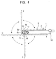
- Fig. 4 is a diagram showing the manner in which the position of the input device is changed.
- an input device 1 is connected to a mobile phone (mobile terminal) 10, and is used while being disposed on an input unit 12, which is provided at the front side of the mobile phone 10 and which includes a plurality of operation keys.
- a display unit 11 including a liquid crystal panel is also provided on a housing of the mobile phone 10 at the front side thereof, and a connecting port 13 (see Fig. 2), to which the input device 1 is connected, is provided at the bottom surface 14 of the mobile phone 10.
- a connecting port 13 see Fig. 2
- the input device of the present invention may also be attached to mobile phones other than the folder-type.
- the input device 1 includes a keyboard-type operating unit 2, and the operating unit 2 includes an operating surface 3, on which a plurality of operation keys is arranged, at the front side thereof.
- a plurality of operation keys is arranged, at the front side thereof.
- ten number keys 3a, twenty-six alphabet keys 3b, two symbol keys 3c, eight special keys 3d, and one cursor-control key 3e are arranged with predetermined gaps therebetween.
- the operating unit 2 includes a thin housing 20.
- the housing 20 is constructed of a base 21, which is formed of a synthetic resin and which is placed at the bottom side of the housing 20, and a cover 25 which covers the surface of the base 21.
- the film-shaped substrate 22 may be formed in, for example, a three-layer structure.
- a top-layer film and a bottom-layer film are laminated together with a spacer film therebetween.
- the top-layer film and the bottom-layer film are provided with connecting points at positions such that the connecting points oppose each other, and the spacer film is provided with holes at positions corresponding to the connecting points.
- a metal contact formed of, for example, a leaf spring may also be used as the elastic pressing member 23.
- a pushing projection 23a is formed at the upper side in each of the hollow portions of the elastic pressing member 23, and keytops 24 formed of resin, rubber, etc., are disposed on the elastic pressing member 23.
- the cover 25 is placed in such a manner that the keytops 24 are inserted through holes 25a formed in the cover 25 and the top surfaces of the keytops 24 project from the cover 25.
- the keytops 24 are provided with flange portions 24a which are integrally formed with the keytops 24, so that the keytops 24 cannot escape from the cover 25.
- the film-shaped substrate 22 may also have a single-layer structure instead of the above-described three-layer substrate.
- a substrate formed of paper phenol, glass epoxy, etc., on which contacting points and a circuit pattern are formed may be used, and a rubber member (rubber spring) having contacting points may be disposed on the substrate.
- the cursor control key 3e shown in Fig. 1 is formed of a button-shaped operating portion which is supported in such a manner that the button-shaped operating portion can be tilted in the X and Y directions and in directions therebetween.
- a cursor (pointer) shown on the display unit 11 moves in a direction corresponding to the direction in which the operating portion is tilted.
- an item selected from a menu (graphs, characters, etc.) shown on the display unit 11 can be changed.
- a decision operation is performed after the desired item is selected, a function corresponding to the selected item is performed.
- the width (the size in the X direction) of the operating unit 2 is made the same as or slightly smaller than the external width of the mobile phone 10. Accordingly, the operating unit 2 does not project from the right and left sides of the mobile phone 10.
- the length of the operating unit 2 in the Y direction is set such that the operating unit 2 does not reach a hinge portion 10a of the mobile phone 10, so that the operating unit 2 can be closely attached to the input portion 12 of the mobile phone 10.
- the input device 1 includes the above-described operating unit 2, a supporting unit 4, and a rotating unit 5.
- the supporting unit 4 includes a supporter 4a, and first shafts 4b and 4b, which are parallel to the bottom surface 14 of the mobile phone 10, project from the supporter 4a at both ends thereof.
- a connector 4c is provided on the side surface of the supporter 4a. The length of the first shafts 4b and 4b is determined such that the first shafts 4b and 4b do not project from the right and left sides of the mobile phone 10.
- the connector 4c of the supporting unit 4 is fitted into the connecting port 13 formed in the bottom surface 14 of the mobile phone 10.
- the connector 4c may be constructed such that it can be exchanged with another connector in accordance with the shape of the connecting port 13.
- the rotating unit 5 includes a pair of rotators 5a and 5a, which are connected to each other with a connecting member 6 in such a manner that the rotators 5a and 5a oppose each other.
- the connecting member 6 connects the rotators 5a and 5a at front ends thereof in the state shown in Fig. 2.
- First bores 5b and 5b which extend in the X direction, are formed in the rotators 5a and 5a, and the inside diameter of the first bores 5b and 5b are made approximately the same as the outside diameter of the first shafts 4b and 4b. Accordingly, the rotating unit 5 is supported by the first shafts 4b and 4b in a rotatable manner.
- a base end portion 2a of the operating unit 2 is provided with second shafts 2c and 2c, which project in the width direction (in the X direction) parallel to the first shafts 4b and 4b.
- second bores 5c and 5c which extend parallel to the second shafts 2c and 2c, are formed in the side surfaces of the rotators 5a and 5a which oppose each other at positions close to the above-described first bores 5b and 5b.
- the outside diameter of the second shafts 2c and 2c is made approximately the same as the inside diameter of the second bores 5c and 5c, so that the operating unit 2 is supported by the second shafts 2c and 2c in a rotatable manner.
- a position conversion unit is formed between the operating unit 2 and the supporting unit 4.
- Fig. 4 the position A shown by the solid lines is an operating position in which the input device 1 is operated and the position D shown by the double-dotted chain lines is a stored position in which the input device 1 is stored.
- the second shafts 2c and 2c are placed at the front side of the mobile phone 10 so that the operating unit 2 can be closely attached to the input unit 12, which is provided at the front side of the mobile phone 10, in such a manner that the operating surface 3 of the operating unit 2 is exposed.
- operation signals are generated and transmitted to the mobile phone 10, and character strings corresponding to the input operation are shown on the display unit 11.
- the character strings shown on the display unit 11 may be, for example, hiragana, katakana, kanji (Chinese characters), Roman alphabet characters, numbers, symbols, pictorial symbols, or combinations thereof.
- corners at the base end of the operating unit 2 are formed as curved portions 2e and 2e, and the rotators 5a and 5a are provided with curved portions 5e and 5e at the end surfaces facing the bottom surface 14 of the mobile phone 10.
- the curved portions 5e and 5e have the same curvature as that of the curved portions 2e and 2e. Accordingly, when the input device 1 is at the position A shown in Fig. 4, the curved portions 2e and 2e are fitted into the curved portions 5e and 5e while the operating unit 2 is closely attached to the surface of the mobile phone 10.
- the operating unit 2 When the operating unit 2 is not used, it is lifted up from the position A, and is rotated in the counterclockwise direction in Fig 4. Thus, the rotating unit 5 supported by the first shafts 4b and 4b is also rotated and the second shafts 2c and 2c are moved toward the bottom surface 14 of the mobile phone 10. Accordingly, the operating unit 2 is moved to the position B.
- the rotating unit 5 supported by the first shafts 4b and 4b is further rotated and the second shafts 2c and 2c are moved to the back side of the operating unit 2.
- the operating unit 2 is moved to the position C, where the operating unit 2 extends horizontally. Since front sides 5d and 5d of the rotators 5a and 5a come into contact with the bottom surface 14 of the mobile phone 10 at this position, the rotating unit 5 does not rotate further in the counterclockwise direction from this position.
- the operating unit 2 When the operating unit 2 is further rotated in the counterclockwise direction from the position C, the operating unit 2 moves to the position D and becomes perpendicular to the back surface of the mobile phone 10, while the positions of the second shafts 2c and 2c do not change. Then, when the operating unit 2 is further rotated in the counterclockwise direction, operating unit 2 is moved to the position E where the operating unit 2 is stored such that the operating unit 2 is closely attached to the back surface of the mobile phone 10. At this position, the operating surface 3 of the operating unit 2 is in contact with the back surface of the mobile phone 10. In addition, both edges of the operating unit 2 in the X direction do not project from the mobile phone 10, so that the operating unit 2 cannot be seen from the front side of the mobile phone 10 except for the supporting unit 4 and the rotating unit 5. Accordingly, the mobile phone 10 can be handled without causing discomfort to the user.
- the position conversion unit including the supporting unit 4 of the input device 1 preferably includes a switching member which allows the input unit 12 of the mobile phone 10 to be operated when the operating unit 2 is at the stored position and allows the keys of the operating unit 2 to be operated when the operating unit 2 is at the operating position.
- a circuit for transmitting the operation signals from the operating unit 2 to the mobile phone 10 may be constructed such that the operation signals are transmitted through the second shaft 2c, the second bore 5c, the first bore 5b, and the first shaft 4b. Accordingly, the operation signals generated in the operating unit 2 can be transmitted to the connecting port 13.
- the operations signals may be transmitted by connecting a flexible substrate on which a wiring pattern is printed to the supporting unit 4 and the operating unit 2.
- an engaging unit may be provided for preventing the operating unit 2 from being moved away from the front surface of the mobile phone 10 when the operating unit 2 is at the operating position and from the back surface of the mobile phone 10 when the operating unit is at the stored position.
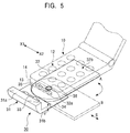
- Fig. 5 is a perspective view of an input device according to a second embodiment of the present invention.
- an input device 30 includes a supporting unit 31 and an operating unit 32.
- the supporting unit 31 is formed in the letter 'L' shape, and includes a side plate 31a which opposes the bottom surface 14 of the mobile phone 10 and a bottom plate 31b which opposes the back surface of the mobile phone 10.
- the width of the supporting unit 31 in the X1-X2 direction is made approximately the same as the width of the mobile phone 10.
- the bottom plate 31b is provided with a step portion 34 having a size corresponding to the thickness (d) of the operating unit 32, and the side surface of the step portion 34 is formed as a curved portion 35 at a position close to the end thereof in the X1 direction.
- the step portion 34 is provided with a shaft 36, which extends perpendicular to the back surface of the mobile phone 10, on the bottom surface thereof.
- the supporting unit 31 is provided with a connector 33 which projects from the supporting unit 31 at the surface facing the bottom surface 14 of the mobile phone 10.
- the operating unit 32 is constructed such that one end thereof in the longitudinal direction is formed in a semicircular shape having the same curvature as that of the above-described curved portion 35.
- a bore 32a which is parallel to the shaft 36, is formed at the center of the semicircle.
- the shaft 36 is inserted in the bore 32a formed in the operating unit 32, so that the operating unit 32 is supported in a rotatable manner.
- the operating unit 32 is able to rotate between a stored position shown by the solid lines (position A) and an operating position shown by the double-dotted chain lines (position B). In the stored position, the operating unit 32 is closely attached to the back surface of the mobile phone 10. When the operating unit 32 is used, it is rotated around the shaft 36 to the operating position so that an operating surface 32b of the operating unit 32 is exposed at the side of the mobile phone 10. In this case, a mechanism for straightly sliding the operating unit 32 from the above-described operating position toward the side (in the S direction) may be provided so that the area of the operating surface 32b which is exposed at the side of the mobile phone 10 can be increased.
- the above-described input device 30 preferably includes a switching member which allows the input unit 12 of the mobile phone 10 to be operated when the operating unit 32 is at the stored position and allows the keys of the operating surface 32b of the operating unit 32 to be operated when the operating unit 32 is at the operating position.
- a circuit for transmitting the operation signals between the operating unit 32 and the mobile phone 10 may be constructed such that the operation signals are transmitted via the shaft 36.
- both edges of the operating unit 32 do not project from the mobile phone 10 when the operating unit 32 is at the stored position (except for the connecting portion). Accordingly, the mobile phone 10 can be handled without causing discomfort to the user.
- the present invention is not limited to this.
- the input device of the present invention may also be attached to, for example, PDAs.
- the operating unit may be constructed such that it is extracted from the side-edge of the mobile terminal as shown in Fig. 5.
- the input devices of the above-described embodiments are constructed such that they can be connected and disconnected to/from the mobile terminal, the present invention is not limited to this.
- the input device of the present invention may also be installed in a mobile terminal in advance.
- an opening may be formed in a side surface of a mobile terminal, and the operating unit may be installed in such a manner that the operating unit is able to project from inside the mobile terminal via the opening.
- the orientation of the character strings shown on the display unit 11 may be changed to a landscape orientation so as to comply with the orientation of the operating surface 3 of the operating unit 2 by a software process performed in the mobile phone 10.
Abstract
Description
- The present invention relates to an input device which is connected to a mobile communication terminal such as a mobile phone and with which characters can be input easily.
- In mobile terminals such as mobile phones and personal digital assistants (PDAs), characters are usually input by the following methods. In mobile phones, characters are input by using a numeric keypad (a group of keys including number keys and keys for the four basic operators). Japanese characters, for example, are input in the form of kana characters (Japanese syllabic alphabet, and there are two types: hiragana and katakana) or romaji (writing system based on Roman characters used to represent Japanese text). In PDAs, characters are input by writing each character on a liquid crystal display with a pen-type input device. In addition, keyboard-type input devices with a plurality of keys arranged thereon are sold separately, and are used for inputting characters by connecting them to the mobile terminals.
- Fig. 6 is a perspective view of a known keyboard-type input device and a mobile terminal to which the keyboard-type input device is connected. With reference to Fig. 6, an
input device 50 includes anoperating unit 51 provided with a plurality ofoperation keys 52 and a connectingcable 53 which extends from theoperating unit 51. The connectingcable 53 is provided with aconnecter 54 at the distal end thereof, and theconnecter 54 is attached to a connectingport 61 formed at the bottom end of amobile terminal 60 in a detachable manner. Themobile terminal 60 includes aninput unit 62 and adisplay unit 63. - In the
input device 50, kana characters and romaji can be input by operating theoperation keys 52. When theoperation keys 52 are pressed, operating data is transmitted to themobile terminal 60, and character strings are displayed on thedisplay unit 63. Then, the character strings are converted into transmission data, which is transmitted from themobile terminal 60 to other mobile terminals. - However, mobile terminals of the known art have the following problems.
- When characters are input to a mobile phone without an input device connected thereto, a single key must be pressed up to five times in order to input a single hiragana character or katakana character, and a single key must be pressed up to three or four times in order to input a single alphabet character. Therefore, a relatively large input time is required. When characters are input to a PDA without an input device connected thereto, there is a problem in that characters are not recognized reliably. In addition, a large input time is also required in this case.
- In the case in which the
input device 50 shown in Fig. 6 is used, the operation to connect and disconnect theinput device 50 to/from the mobile terminal is cumbersome. In addition, since theinput device 50 and themobile terminal 60 are connected to each other with the connecting cable, the user cannot input characters easily and smoothly while holding both theinput device 50 and themobile terminal 60. Furthermore, since theinput device 50 must be disconnected from themobile terminal 60 and carried separately when it is not being used, theinput device 50 is not carried conveniently. - In order to solve the above-described problems, an object of the present invention is to provide an input device with which characters can be input quickly and reliably and which can be carried conveniently.
- An input device of according to the present invention includes a supporting unit including a connector which is detachably connected to a mobile terminal having a display unit; an operating unit which transmits an operation signal to the mobile terminal via the connector; a plurality of operation keys provided on an operating surface of the operating unit; and a position converting unit which is formed between the supporting unit and the operating unit, and which, while the connector is connected to the mobile terminal, allows the operating unit to rotate between a stored position at which the operating unit is hidden behind the mobile terminal and an operating position at which the operating surface is exposed at a position such that the operating surface can be operated.
- Preferably, when the operating unit is at the operating position, the operating unit is disposed on the front surface of the mobile terminal in such a manner that the operating surface faces upward.
- An input unit may be provided on the front surface of the mobile terminal in addition to the display unit and the operating unit is disposed on the input unit when the operating unit is at the operating position. It becomes possible to operate the input unit of the mobile terminal when the operating unit is at the stored position, and it becomes possible to operate the operation keys of the operating unit when the operating unit is at the operating position.
- The connecter may be connected to a connecting port provided at the bottom-end surface of the mobile terminal, and the position converting unit may include a rotating unit which is connected to the supporting unit by first shafts in a rotatable manner, the first shafts extending parallel to the bottom-end surface, and the operating unit may be supported by second shafts in a rotatable manner at a base end portion of the operating unit, the second shafts extending parallel to the first shafts. When the rotating unit is rotated in one direction, the second shafts are moved to the front side of the mobile terminal and the operating unit is moved to the operating position at which the operating unit is closely attached to the front surface of the mobile terminal, and when the rotating unit is rotated in the other direction, the second shafts are moved to the back side of the mobile terminal and the operating unit is moved to the stored position at which the operating unit is closely attached to the back surface of the mobile terminal.
- The position converting unit may be constructed such that the operating unit is connected to the supporting unit in a rotatable manner by a shaft which extends perpendicular to the back surface of the mobile terminal, and the operating unit may be moved between the stored position at which the operating unit is disposed behind the back surface of the mobile terminal and the operating position at which the operating surface is exposed at a side of the mobile terminal by rotating the operating unit around the shaft.
- According to the above-described input device of the present invention, characters can be input quickly and reliably compared with the cases in which characters are input by using a pen-type input device or a keyboard as in the known art. In addition, since the input device of the present invention can be reliably attached to the mobile terminal without causing the operating unit to rattle, the input operation can be easily performed. Furthermore, since the input device does not become cumbersome when it is attached to the mobile terminal, the mobile terminal can be conveniently carried and handled without causing discomfort to the user.
- An embodiment of the present invention will now be described, by way of example, with reference to the accompanying diagrammatic drawings, in which:
- Fig. 1 is a plan view of an input device according to a first embodiment of the present invention in a state in which the input device is used;
- Fig. 2 is an exploded perspective view of the input device;
- Fig. 3 is a sectional view of an operating unit of the input device;
- Fig. 4 is a diagram showing a manner in which the position of the input device is changed;
- Fig. 5 is a perspective view showing an input device according to a second embodiment of the present invention; and
- Fig. 6 is a perspective view of a known input device in a state in which the input device is used.
-
- Fig. 1 is a plan view of an input device according to a first embodiment of the present invention in a state in which the input device is used, and Fig. 2 is an exploded perspective view of the input device. In addition, Fig. 3 is a sectional view of an operating unit of the input device, and Fig. 4 is a diagram showing the manner in which the position of the input device is changed.
- With reference to Fig. 1, an input device 1 is connected to a mobile phone (mobile terminal) 10, and is used while being disposed on an
input unit 12, which is provided at the front side of themobile phone 10 and which includes a plurality of operation keys. In addition to theinput unit 12, adisplay unit 11 including a liquid crystal panel is also provided on a housing of themobile phone 10 at the front side thereof, and a connecting port 13 (see Fig. 2), to which the input device 1 is connected, is provided at thebottom surface 14 of themobile phone 10. Although mobile phones of the folder-type will be described in the following embodiments as examples, the input device of the present invention may also be attached to mobile phones other than the folder-type. - The input device 1 includes a keyboard-
type operating unit 2, and theoperating unit 2 includes anoperating surface 3, on which a plurality of operation keys is arranged, at the front side thereof. As shown in Fig. 1, for example, tennumber keys 3a, twenty-sixalphabet keys 3b, twosymbol keys 3c, eightspecial keys 3d, and one cursor-control key 3e are arranged with predetermined gaps therebetween. - As shown in Fig. 3, the
operating unit 2 includes athin housing 20. Thehousing 20 is constructed of abase 21, which is formed of a synthetic resin and which is placed at the bottom side of thehousing 20, and acover 25 which covers the surface of thebase 21. - A film-
shaped substrate 22, which is provided with a wiring pattern on the top surface thereof, is laminated on thebase 21. Although not shown in the figure, the film-shaped substrate 22 may be formed in, for example, a three-layer structure. In the film-shaped substrate 22 having a three-layer structure, a top-layer film and a bottom-layer film are laminated together with a spacer film therebetween. The top-layer film and the bottom-layer film are provided with connecting points at positions such that the connecting points oppose each other, and the spacer film is provided with holes at positions corresponding to the connecting points. An elastic pressingmember 23, which is formed of rubber and which is provided with hollow portions, is disposed on the film-shaped substrate 22 in such a manner that the hollow portions are placed at positions corresponding to the connecting points of the film-shaped substrate 22. Alternatively, a metal contact formed of, for example, a leaf spring, may also be used as the elastic pressingmember 23. A pushingprojection 23a is formed at the upper side in each of the hollow portions of the elastic pressingmember 23, andkeytops 24 formed of resin, rubber, etc., are disposed on the elastic pressingmember 23. Thecover 25 is placed in such a manner that thekeytops 24 are inserted throughholes 25a formed in thecover 25 and the top surfaces of thekeytops 24 project from thecover 25. Thekeytops 24 are provided withflange portions 24a which are integrally formed with thekeytops 24, so that thekeytops 24 cannot escape from thecover 25. - The film-
shaped substrate 22 may also have a single-layer structure instead of the above-described three-layer substrate. In such a case, a substrate formed of paper phenol, glass epoxy, etc., on which contacting points and a circuit pattern are formed may be used, and a rubber member (rubber spring) having contacting points may be disposed on the substrate. - In the above-described
operating unit 2, when one of thekeytops 24 is pressed by a finger, the elastic pressingmember 23 is bent. Accordingly, the contacting points of the top film and the bottom film come into contact with each other, and an operation signal including character information, etc., is generated. Then, when the pressing force applied to thekeytop 24 is removed, thekeytop 24 returns to its initial position by the restoring force applied by the elastic pressingmember 23. - The
cursor control key 3e shown in Fig. 1 is formed of a button-shaped operating portion which is supported in such a manner that the button-shaped operating portion can be tilted in the X and Y directions and in directions therebetween. When the operating portion is pushed and tilted in a desired direction, a cursor (pointer) shown on thedisplay unit 11 moves in a direction corresponding to the direction in which the operating portion is tilted. Alternatively, an item selected from a menu (graphs, characters, etc.) shown on thedisplay unit 11 can be changed. When a decision operation is performed after the desired item is selected, a function corresponding to the selected item is performed. - In the input device 1 according to the present embodiment, the width (the size in the X direction) of the
operating unit 2 is made the same as or slightly smaller than the external width of themobile phone 10. Accordingly, theoperating unit 2 does not project from the right and left sides of themobile phone 10. In addition, in the input device 1, the length of theoperating unit 2 in the Y direction is set such that theoperating unit 2 does not reach ahinge portion 10a of themobile phone 10, so that theoperating unit 2 can be closely attached to theinput portion 12 of themobile phone 10. - As shown in Fig. 2, the input device 1 includes the above-described
operating unit 2, a supportingunit 4, and a rotating unit 5. - The supporting
unit 4 includes asupporter 4a, andfirst shafts bottom surface 14 of themobile phone 10, project from thesupporter 4a at both ends thereof. In addition, aconnector 4c is provided on the side surface of thesupporter 4a. The length of thefirst shafts first shafts mobile phone 10. - The
connector 4c of the supportingunit 4 is fitted into the connectingport 13 formed in thebottom surface 14 of themobile phone 10. Theconnector 4c may be constructed such that it can be exchanged with another connector in accordance with the shape of the connectingport 13. - The rotating unit 5 includes a pair of
rotators member 6 in such a manner that therotators member 6 connects therotators - First bores 5b and 5b, which extend in the X direction, are formed in the
rotators first bores first shafts first shafts - A base end portion 2a of the
operating unit 2 is provided withsecond shafts first shafts second bores second shafts rotators first bores second shafts second bores operating unit 2 is supported by thesecond shafts - In the input device 1 which is constructed as described above, a position conversion unit is formed between the operating
unit 2 and the supportingunit 4. - Next, the manner in which the position of the input device 1 is changed will be described below with reference to Fig. 4. In Fig. 4, the position A shown by the solid lines is an operating position in which the input device 1 is operated and the position D shown by the double-dotted chain lines is a stored position in which the input device 1 is stored.
- At the position A, the
second shafts mobile phone 10 so that theoperating unit 2 can be closely attached to theinput unit 12, which is provided at the front side of themobile phone 10, in such a manner that the operatingsurface 3 of theoperating unit 2 is exposed. When theoperation keys 3a to 3e are operated while the input device 1 is at this position, operation signals are generated and transmitted to themobile phone 10, and character strings corresponding to the input operation are shown on thedisplay unit 11. The character strings shown on thedisplay unit 11 may be, for example, hiragana, katakana, kanji (Chinese characters), Roman alphabet characters, numbers, symbols, pictorial symbols, or combinations thereof. - As shown in Fig. 2, corners at the base end of the
operating unit 2 are formed ascurved portions rotators curved portions bottom surface 14 of themobile phone 10. Thecurved portions curved portions curved portions curved portions operating unit 2 is closely attached to the surface of themobile phone 10. - When the
operating unit 2 is not used, it is lifted up from the position A, and is rotated in the counterclockwise direction in Fig 4. Thus, the rotating unit 5 supported by thefirst shafts second shafts bottom surface 14 of themobile phone 10. Accordingly, theoperating unit 2 is moved to the position B. - Then, when the
operating unit 2 is further rotated in the counterclockwise direction from the position B, the rotating unit 5 supported by thefirst shafts second shafts operating unit 2. Thus, theoperating unit 2 is moved to the position C, where theoperating unit 2 extends horizontally. Sincefront sides rotators bottom surface 14 of themobile phone 10 at this position, the rotating unit 5 does not rotate further in the counterclockwise direction from this position. - When the
operating unit 2 is further rotated in the counterclockwise direction from the position C, theoperating unit 2 moves to the position D and becomes perpendicular to the back surface of themobile phone 10, while the positions of thesecond shafts operating unit 2 is further rotated in the counterclockwise direction, operatingunit 2 is moved to the position E where theoperating unit 2 is stored such that theoperating unit 2 is closely attached to the back surface of themobile phone 10. At this position, the operatingsurface 3 of theoperating unit 2 is in contact with the back surface of themobile phone 10. In addition, both edges of theoperating unit 2 in the X direction do not project from themobile phone 10, so that theoperating unit 2 cannot be seen from the front side of themobile phone 10 except for the supportingunit 4 and the rotating unit 5. Accordingly, themobile phone 10 can be handled without causing discomfort to the user. - Although not shown in the figure, the position conversion unit including the supporting
unit 4 of the input device 1 preferably includes a switching member which allows theinput unit 12 of themobile phone 10 to be operated when theoperating unit 2 is at the stored position and allows the keys of theoperating unit 2 to be operated when theoperating unit 2 is at the operating position. A circuit for transmitting the operation signals from theoperating unit 2 to themobile phone 10 may be constructed such that the operation signals are transmitted through thesecond shaft 2c, thesecond bore 5c, thefirst bore 5b, and thefirst shaft 4b. Accordingly, the operation signals generated in theoperating unit 2 can be transmitted to the connectingport 13. Alternatively, the operations signals may be transmitted by connecting a flexible substrate on which a wiring pattern is printed to the supportingunit 4 and theoperating unit 2. - In addition, an engaging unit may be provided for preventing the
operating unit 2 from being moved away from the front surface of themobile phone 10 when theoperating unit 2 is at the operating position and from the back surface of themobile phone 10 when the operating unit is at the stored position. - Fig. 5 is a perspective view of an input device according to a second embodiment of the present invention.
- With reference to Fig. 5, an
input device 30 includes a supportingunit 31 and anoperating unit 32. The supportingunit 31 is formed in the letter 'L' shape, and includes aside plate 31a which opposes thebottom surface 14 of themobile phone 10 and abottom plate 31b which opposes the back surface of themobile phone 10. The width of the supportingunit 31 in the X1-X2 direction is made approximately the same as the width of themobile phone 10. In addition, thebottom plate 31b is provided with astep portion 34 having a size corresponding to the thickness (d) of the operatingunit 32, and the side surface of thestep portion 34 is formed as a curved portion 35 at a position close to the end thereof in the X1 direction. - In the supporting
unit 31, thestep portion 34 is provided with ashaft 36, which extends perpendicular to the back surface of themobile phone 10, on the bottom surface thereof. In addition, the supportingunit 31 is provided with aconnector 33 which projects from the supportingunit 31 at the surface facing thebottom surface 14 of themobile phone 10. - The operating
unit 32 is constructed such that one end thereof in the longitudinal direction is formed in a semicircular shape having the same curvature as that of the above-described curved portion 35. In addition, abore 32a, which is parallel to theshaft 36, is formed at the center of the semicircle. - As shown in Fig. 5, the
shaft 36 is inserted in thebore 32a formed in the operatingunit 32, so that the operatingunit 32 is supported in a rotatable manner. - In the
input device 30 which is formed as described above, the operatingunit 32 is able to rotate between a stored position shown by the solid lines (position A) and an operating position shown by the double-dotted chain lines (position B). In the stored position, the operatingunit 32 is closely attached to the back surface of themobile phone 10. When the operatingunit 32 is used, it is rotated around theshaft 36 to the operating position so that anoperating surface 32b of the operatingunit 32 is exposed at the side of themobile phone 10. In this case, a mechanism for straightly sliding the operatingunit 32 from the above-described operating position toward the side (in the S direction) may be provided so that the area of theoperating surface 32b which is exposed at the side of themobile phone 10 can be increased. - The above-described
input device 30 preferably includes a switching member which allows theinput unit 12 of themobile phone 10 to be operated when the operatingunit 32 is at the stored position and allows the keys of theoperating surface 32b of the operatingunit 32 to be operated when the operatingunit 32 is at the operating position. In the second embodiment, a circuit for transmitting the operation signals between the operatingunit 32 and themobile phone 10 may be constructed such that the operation signals are transmitted via theshaft 36. - Similar to the above-described
input device 10, in theinput device 30 shown in Fig. 5, both edges of the operatingunit 32 do not project from themobile phone 10 when the operatingunit 32 is at the stored position (except for the connecting portion). Accordingly, themobile phone 10 can be handled without causing discomfort to the user. - Although cases in which the input devices are attached to a mobile phone are explained in the above-described embodiments, the present invention is not limited to this. The input device of the present invention may also be attached to, for example, PDAs. In such a case, the operating unit may be constructed such that it is extracted from the side-edge of the mobile terminal as shown in Fig. 5.
- In addition, although the input devices of the above-described embodiments are constructed such that they can be connected and disconnected to/from the mobile terminal, the present invention is not limited to this. The input device of the present invention may also be installed in a mobile terminal in advance. For example, an opening may be formed in a side surface of a mobile terminal, and the operating unit may be installed in such a manner that the operating unit is able to project from inside the mobile terminal via the opening.
- In addition, when the input device 1 is at the operating position as shown in Fig. 1, the orientation of the character strings shown on the
display unit 11 may be changed to a landscape orientation so as to comply with the orientation of theoperating surface 3 of theoperating unit 2 by a software process performed in themobile phone 10.
Claims (5)
- An input device comprising:a supporting unit including a connector which is detachably connected to a mobile terminal having a display unit;an operating unit which transmits an operation signal to the mobile terminal via the connector;a plurality of operation keys provided on an operating surface of the operating unit; andposition converting means which is formed between the supporting unit and the operating unit, and which, while the connector is connected to the mobile terminal, allows the operating unit to rotate between a stored position at which the operating unit is hidden behind the mobile terminal and an operating position at which the operating surface is exposed at a position such that the operating surface can be operated.
- An input device according to Claim 1, wherein, when the operating unit is at the operating position, the operating unit is disposed on the front surface of the mobile terminal in such a manner that the operating surface faces upward.
- An input device according to Claim 2, wherein an input unit is provided on the front surface of the mobile terminal in addition to the display unit and the operating unit is disposed on the input unit when the operating unit is at the operating position, and
wherein it becomes possible to operate the input unit of the mobile terminal when the operating unit is at the stored position and it becomes possible to operate the operation keys of the operating unit when the operating unit is at the operating position. - An input device according to Claim 2, wherein the connecter is connected to a connecting port provided at the bottom-end surface of the mobile terminal,
wherein the position converting means includes a rotating unit which is connected to the supporting unit by first shafts in a rotatable manner, the first shafts extending parallel to the bottom-end surface, and the operating unit is supported by second shafts in a rotatable manner at a base end portion of the operating unit, the second shafts extending parallel to the first shafts, and
wherein, when the rotating unit is rotated in one direction, the second shafts are moved to the front side of the mobile terminal and the operating unit is moved to the operating position at which the operating unit is closely attached to the front surface of the mobile terminal, and when the rotating unit is rotated in the other direction, the second shafts are moved to the back side of the mobile terminal and the operating unit is moved to the stored position at which the operating unit is closely attached to the back surface of the mobile terminal. - An input device according to Claim 1, wherein the position converting means is constructed such that the operating unit is connected to the supporting unit in a rotatable manner by a shaft which extends perpendicular to the back surface of the mobile terminal, and
wherein the operating unit is moved between the stored position at which the operating unit is disposed behind the back surface of the mobile terminal and the operating position at which the operating surface is exposed at a side of the mobile terminal by rotating the operating unit around the shaft.
Applications Claiming Priority (2)
| Application Number | Priority Date | Filing Date | Title |
|---|---|---|---|
| JP2001144072A JP3964154B2 (en) | 2001-05-15 | 2001-05-15 | Input device for portable terminal |
| JP2001144072 | 2001-05-15 |
Publications (2)
| Publication Number | Publication Date |
|---|---|
| EP1259048A2 true EP1259048A2 (en) | 2002-11-20 |
| EP1259048A3 EP1259048A3 (en) | 2004-01-14 |
Family
ID=18990082
Family Applications (1)
| Application Number | Title | Priority Date | Filing Date |
|---|---|---|---|
| EP02253161A Withdrawn EP1259048A3 (en) | 2001-05-15 | 2002-05-04 | Input device connected to mobile communication terminal with which characters can be input easily |
Country Status (3)
| Country | Link |
|---|---|
| US (1) | US7107083B2 (en) |
| EP (1) | EP1259048A3 (en) |
| JP (1) | JP3964154B2 (en) |
Cited By (3)
| Publication number | Priority date | Publication date | Assignee | Title |
|---|---|---|---|---|
| EP1422593A1 (en) * | 2002-11-21 | 2004-05-26 | Sony Ericsson Mobile Communications AB | Flexible conductors connected between two parts of a portable electronic device |
| US7483723B2 (en) | 2002-11-21 | 2009-01-27 | Sony Ericsson Mobile Communications Ab | Flexible conductors connected between two parts of a portable electronic device |
| EP2280527A1 (en) * | 2009-07-07 | 2011-02-02 | LG Electronics Inc. | Mobile terminal with foldable keypad |
Families Citing this family (9)
| Publication number | Priority date | Publication date | Assignee | Title |
|---|---|---|---|---|
| KR100464368B1 (en) * | 2003-01-06 | 2005-01-03 | 삼성전자주식회사 | Combination terminal and method capable of performing independently operation two device |
| CN100418337C (en) * | 2003-05-06 | 2008-09-10 | 三星电子株式会社 | Portable communication apparatus having improved capability in inputting data |
| CN100394763C (en) * | 2004-09-15 | 2008-06-11 | 索尼株式会社 | Input device |
| US7779462B2 (en) * | 2005-04-11 | 2010-08-17 | Microsoft Corporation | Switching an application, user and security context based on device orientation |
| CA2544450A1 (en) * | 2006-04-21 | 2007-10-21 | 2932105 Canada Inc. | Calculator with integrated memo pad holder |
| US8174501B2 (en) | 2008-05-06 | 2012-05-08 | Google Inc. | Computer having interlocking L-shape components |
| US8279589B2 (en) * | 2010-02-01 | 2012-10-02 | Christine Hana Kim | Apparatus and method for data entry from a removable portable device cover |
| JP5565858B2 (en) * | 2010-04-26 | 2014-08-06 | Necカシオモバイルコミュニケーションズ株式会社 | Mobile communication terminal |
| US8858335B2 (en) * | 2013-01-18 | 2014-10-14 | Microsoft Corporation | Reconfigurable clip-on modules for mobile computing devices |
Citations (3)
| Publication number | Priority date | Publication date | Assignee | Title |
|---|---|---|---|---|
| WO1998019434A1 (en) * | 1996-10-29 | 1998-05-07 | Ericsson Inc. | Telecommunication apparatus having dual keypads |
| US6147858A (en) * | 1998-03-31 | 2000-11-14 | Fujitsu Takamisawa Components Company | Keyboard unit and portable type information apparatus having the same |
| WO2001022695A1 (en) * | 1999-09-21 | 2001-03-29 | Telefonaktiebolaget L M Ericsson (Publ) | A portable communication apparatus having first and second user interfaces, and an accessory device comprising a keypad and a display for a portable radio telephone |
Family Cites Families (7)
| Publication number | Priority date | Publication date | Assignee | Title |
|---|---|---|---|---|
| JPH08126050A (en) | 1994-10-26 | 1996-05-17 | Toyo Commun Equip Co Ltd | Structure of hinge part for portable telephone set |
| US5666694A (en) * | 1995-09-28 | 1997-09-16 | Hewlett-Packard Company | Hinge arrangement |
| US6542721B2 (en) * | 1999-10-11 | 2003-04-01 | Peter V. Boesen | Cellular telephone, personal digital assistant and pager unit |
| US6385463B1 (en) * | 1999-10-26 | 2002-05-07 | Qualcomm Incorporated | Wireless communication device with detachable flip keyboard |
| US6370018B1 (en) * | 2000-08-18 | 2002-04-09 | William B. Miller, Jr. | Portable computer keyboard |
| US6888534B1 (en) * | 2001-01-30 | 2005-05-03 | Palmone, Inc. | Segmented keyboard for portable computer system |
| US6671170B2 (en) * | 2001-02-07 | 2003-12-30 | Palm, Inc. | Miniature keyboard for a hand held computer |
-
2001
- 2001-05-15 JP JP2001144072A patent/JP3964154B2/en not_active Expired - Fee Related
-
2002
- 2002-05-04 EP EP02253161A patent/EP1259048A3/en not_active Withdrawn
- 2002-05-10 US US10/144,206 patent/US7107083B2/en not_active Expired - Fee Related
Patent Citations (3)
| Publication number | Priority date | Publication date | Assignee | Title |
|---|---|---|---|---|
| WO1998019434A1 (en) * | 1996-10-29 | 1998-05-07 | Ericsson Inc. | Telecommunication apparatus having dual keypads |
| US6147858A (en) * | 1998-03-31 | 2000-11-14 | Fujitsu Takamisawa Components Company | Keyboard unit and portable type information apparatus having the same |
| WO2001022695A1 (en) * | 1999-09-21 | 2001-03-29 | Telefonaktiebolaget L M Ericsson (Publ) | A portable communication apparatus having first and second user interfaces, and an accessory device comprising a keypad and a display for a portable radio telephone |
Cited By (4)
| Publication number | Priority date | Publication date | Assignee | Title |
|---|---|---|---|---|
| EP1422593A1 (en) * | 2002-11-21 | 2004-05-26 | Sony Ericsson Mobile Communications AB | Flexible conductors connected between two parts of a portable electronic device |
| US7483723B2 (en) | 2002-11-21 | 2009-01-27 | Sony Ericsson Mobile Communications Ab | Flexible conductors connected between two parts of a portable electronic device |
| EP2280527A1 (en) * | 2009-07-07 | 2011-02-02 | LG Electronics Inc. | Mobile terminal with foldable keypad |
| US8681103B2 (en) | 2009-07-07 | 2014-03-25 | Lg Electronics Inc. | Mobile terminal |
Also Published As
| Publication number | Publication date |
|---|---|
| JP2002341997A (en) | 2002-11-29 |
| US7107083B2 (en) | 2006-09-12 |
| EP1259048A3 (en) | 2004-01-14 |
| JP3964154B2 (en) | 2007-08-22 |
| US20020173340A1 (en) | 2002-11-21 |
Similar Documents
| Publication | Publication Date | Title |
|---|---|---|
| CN100545788C (en) | The portable electric appts that has keyboard | |
| US6507336B1 (en) | Keyboard for a handheld computer | |
| JP4477353B2 (en) | Handheld electronic device with keyboard | |
| KR100916619B1 (en) | Handheld mobile communication device | |
| KR100564687B1 (en) | Adaptable keypad and button mechanism therefor | |
| KR100422383B1 (en) | Terminal device | |
| US20050125570A1 (en) | Portable communication devices | |
| US20050091431A1 (en) | Portable communication devices | |
| US6744890B1 (en) | Keypad module and electronic apparatus with keypad module | |
| JP2009259263A (en) | Keyboard arrangement | |
| US20050190160A1 (en) | Handheld electronic device | |
| US7107083B2 (en) | Input device connected to mobile communication terminal with which characters can be input easily | |
| US20030117374A1 (en) | Portable electronic device with rear-facing touch typing keyboard | |
| JP2007141249A (en) | Keyboard arrangement | |
| EP2073509A1 (en) | Portable electronic device | |
| JP2002328762A (en) | Keyboard unit | |
| JP4917114B2 (en) | Trackball socket for handheld wireless communication devices | |
| JP2006040155A (en) | Portable electronic device | |
| EP1628195A1 (en) | Handheld electronic device | |
| JP2007122742A (en) | Keyboard layout | |
| JP2003167665A (en) | Input device | |
| KR20040077165A (en) | Mobile communication terminal having slide type keypad | |
| KR20030050169A (en) | A key-inputting apparatus for a personal mobile telephone |
Legal Events
| Date | Code | Title | Description |
|---|---|---|---|
| PUAI | Public reference made under article 153(3) epc to a published international application that has entered the european phase |
Free format text: ORIGINAL CODE: 0009012 |
|
| AK | Designated contracting states |
Kind code of ref document: A2 Designated state(s): AT BE CH CY DE DK ES FI FR GB GR IE IT LI LU MC NL PT SE TR |
|
| AX | Request for extension of the european patent |
Free format text: AL;LT;LV;MK;RO;SI |
|
| PUAL | Search report despatched |
Free format text: ORIGINAL CODE: 0009013 |
|
| AK | Designated contracting states |
Kind code of ref document: A3 Designated state(s): AT BE CH CY DE DK ES FI FR GB GR IE IT LI LU MC NL PT SE TR |
|
| AX | Request for extension of the european patent |
Extension state: AL LT LV MK RO SI |
|
| 17P | Request for examination filed |
Effective date: 20040130 |
|
| 17Q | First examination report despatched |
Effective date: 20040326 |
|
| AKX | Designation fees paid |
Designated state(s): DE FR GB |
|
| STAA | Information on the status of an ep patent application or granted ep patent |
Free format text: STATUS: THE APPLICATION IS DEEMED TO BE WITHDRAWN |
|
| 18D | Application deemed to be withdrawn |
Effective date: 20101201 |