EP1267313A2 - Image surveillance apparatus, image surveillance method, and image surveillance processing program - Google Patents
Image surveillance apparatus, image surveillance method, and image surveillance processing program Download PDFInfo
- Publication number
- EP1267313A2 EP1267313A2 EP02254066A EP02254066A EP1267313A2 EP 1267313 A2 EP1267313 A2 EP 1267313A2 EP 02254066 A EP02254066 A EP 02254066A EP 02254066 A EP02254066 A EP 02254066A EP 1267313 A2 EP1267313 A2 EP 1267313A2
- Authority
- EP
- European Patent Office
- Prior art keywords
- image
- surveillance
- image data
- section
- region
- Prior art date
- Legal status (The legal status is an assumption and is not a legal conclusion. Google has not performed a legal analysis and makes no representation as to the accuracy of the status listed.)
- Granted
Links
Images


Classifications
-
- H—ELECTRICITY
- H04—ELECTRIC COMMUNICATION TECHNIQUE
- H04N—PICTORIAL COMMUNICATION, e.g. TELEVISION
- H04N7/00—Television systems
- H04N7/18—Closed-circuit television [CCTV] systems, i.e. systems in which the video signal is not broadcast
-
- G—PHYSICS
- G08—SIGNALLING
- G08B—SIGNALLING OR CALLING SYSTEMS; ORDER TELEGRAPHS; ALARM SYSTEMS
- G08B13/00—Burglar, theft or intruder alarms
- G08B13/18—Actuation by interference with heat, light, or radiation of shorter wavelength; Actuation by intruding sources of heat, light, or radiation of shorter wavelength
- G08B13/189—Actuation by interference with heat, light, or radiation of shorter wavelength; Actuation by intruding sources of heat, light, or radiation of shorter wavelength using passive radiation detection systems
- G08B13/194—Actuation by interference with heat, light, or radiation of shorter wavelength; Actuation by intruding sources of heat, light, or radiation of shorter wavelength using passive radiation detection systems using image scanning and comparing systems
- G08B13/196—Actuation by interference with heat, light, or radiation of shorter wavelength; Actuation by intruding sources of heat, light, or radiation of shorter wavelength using passive radiation detection systems using image scanning and comparing systems using television cameras
- G08B13/19602—Image analysis to detect motion of the intruder, e.g. by frame subtraction
- G08B13/19604—Image analysis to detect motion of the intruder, e.g. by frame subtraction involving reference image or background adaptation with time to compensate for changing conditions, e.g. reference image update on detection of light level change
-
- G—PHYSICS
- G08—SIGNALLING
- G08B—SIGNALLING OR CALLING SYSTEMS; ORDER TELEGRAPHS; ALARM SYSTEMS
- G08B13/00—Burglar, theft or intruder alarms
- G08B13/18—Actuation by interference with heat, light, or radiation of shorter wavelength; Actuation by intruding sources of heat, light, or radiation of shorter wavelength
- G08B13/189—Actuation by interference with heat, light, or radiation of shorter wavelength; Actuation by intruding sources of heat, light, or radiation of shorter wavelength using passive radiation detection systems
- G08B13/194—Actuation by interference with heat, light, or radiation of shorter wavelength; Actuation by intruding sources of heat, light, or radiation of shorter wavelength using passive radiation detection systems using image scanning and comparing systems
- G08B13/196—Actuation by interference with heat, light, or radiation of shorter wavelength; Actuation by intruding sources of heat, light, or radiation of shorter wavelength using passive radiation detection systems using image scanning and comparing systems using television cameras
- G08B13/19617—Surveillance camera constructional details
- G08B13/19626—Surveillance camera constructional details optical details, e.g. lenses, mirrors or multiple lenses
- G08B13/19628—Surveillance camera constructional details optical details, e.g. lenses, mirrors or multiple lenses of wide angled cameras and camera groups, e.g. omni-directional cameras, fish eye, single units having multiple cameras achieving a wide angle view
-
- G—PHYSICS
- G08—SIGNALLING
- G08B—SIGNALLING OR CALLING SYSTEMS; ORDER TELEGRAPHS; ALARM SYSTEMS
- G08B13/00—Burglar, theft or intruder alarms
- G08B13/18—Actuation by interference with heat, light, or radiation of shorter wavelength; Actuation by intruding sources of heat, light, or radiation of shorter wavelength
- G08B13/189—Actuation by interference with heat, light, or radiation of shorter wavelength; Actuation by intruding sources of heat, light, or radiation of shorter wavelength using passive radiation detection systems
- G08B13/194—Actuation by interference with heat, light, or radiation of shorter wavelength; Actuation by intruding sources of heat, light, or radiation of shorter wavelength using passive radiation detection systems using image scanning and comparing systems
- G08B13/196—Actuation by interference with heat, light, or radiation of shorter wavelength; Actuation by intruding sources of heat, light, or radiation of shorter wavelength using passive radiation detection systems using image scanning and comparing systems using television cameras
- G08B13/19617—Surveillance camera constructional details
- G08B13/1963—Arrangements allowing camera rotation to change view, e.g. pivoting camera, pan-tilt and zoom [PTZ]
-
- G—PHYSICS
- G08—SIGNALLING
- G08B—SIGNALLING OR CALLING SYSTEMS; ORDER TELEGRAPHS; ALARM SYSTEMS
- G08B13/00—Burglar, theft or intruder alarms
- G08B13/18—Actuation by interference with heat, light, or radiation of shorter wavelength; Actuation by intruding sources of heat, light, or radiation of shorter wavelength
- G08B13/189—Actuation by interference with heat, light, or radiation of shorter wavelength; Actuation by intruding sources of heat, light, or radiation of shorter wavelength using passive radiation detection systems
- G08B13/194—Actuation by interference with heat, light, or radiation of shorter wavelength; Actuation by intruding sources of heat, light, or radiation of shorter wavelength using passive radiation detection systems using image scanning and comparing systems
- G08B13/196—Actuation by interference with heat, light, or radiation of shorter wavelength; Actuation by intruding sources of heat, light, or radiation of shorter wavelength using passive radiation detection systems using image scanning and comparing systems using television cameras
- G08B13/19665—Details related to the storage of video surveillance data
- G08B13/19671—Addition of non-video data, i.e. metadata, to video stream
- G08B13/19673—Addition of time stamp, i.e. time metadata, to video stream
Definitions
- the present invention relates to an image surveillance apparatus having an imaging device installed so as to observe a certain surveillance region, wherein an image obtained by this imaging device is processed in order to detect a person or object which intrudes into the surveillance region.
- the present invention further relates to an image surveillance method and an image surveillance processing program implemented in such an image surveillance apparatus.
- an imaging device such as an industrial television camera (hereinafter “ITV camera”), or the like, has been used in surveillance apparatuses.
- ITV camera industrial television camera
- These kind of surveillance apparatuses are installed at an appropriate place in a factory building.
- the surveillance apparatus monitors an image obtained by an imaging device of the surveillance apparatus.
- Such a surveillance apparatus has been effectively used for improving security of a factory building by detecting occurrence of an abnormal event and intrusion of criminals into the factory building.
- an image of a certain region to be monitored is obtained by an ITV camera installed on a ceiling, or the like, and the image obtained by the ITV camera is used as a surveillance image for surveilling the surveillance region.
- the surveillance apparatus compares the surveillance image of the surveillance region, which is captured by the ITV camera and updated every predetermined time (hereinafter, referred to as "current image"), with a surveillance reference image, which is a background constantly present in the surveillance region and which is previously stored in the surveillance apparatus (hereinafter, referred to as "background image"). If the current image differs from the background image, the surveillance apparatus determines that there is an intruder, or the like, in the surveillance region.
- the surveillance apparatus When the surveillance apparatus detects intrusion of an intruder as a result of the comparison between the current image and the background image, for example, the surveillance apparatus informs a surveillant or operator who is monitoring the surveillance region through the surveillance apparatus that an intruder is detected. The surveillant informed of that intrusion goes to the place in the surveillance region where intrusion was detected, or takes any necessary action.
- the angle of view of an imaging device is narrow, such that the surveillance region that is covered by a single imaging device is limited.
- a plurality of imaging devices have to be installed at appropriate positions so that the entire surveillance region can be covered by the imaging devices.
- an imaging device has to be movable so that a large surveillance region can be covered by the single imaging device.
- an image surveillance apparatus includes: an imaging section including a convex mirror having a shape of a body of rotation, the imaging section obtaining an image of an omniazimuthal region and generating image data of the omniazimuthal region; a surveillance region setting section for setting a surveillance region in the image data of the omniazimuthal region which is obtained from the imaging section; an image processing section for performing image processing according to determination information obtained from a comparison/determination between background image data obtained by the imaging section in advance, which is used as a reference that represents a normal state of the surveillance region, and current image data obtained by the imaging section at a predetermined time interval; and a surveillance information output section for outputting surveillance information according to the determination information.
- the surveillance information output section is an image output section.
- the image processing section includes: an image comparison section for comparing the background image data and the current image data; a determination section for determining the presence/absence of an object to be examined based on a comparison result of the image comparison section; and an image conversion section for performing certain image conversion processing based on the determination result of the determination section.
- the surveillance region setting section sets a plurality of surveillance regions.
- the image processing section converts the image data of the omniazimuthal region, which is obtained by the imaging section, into panoramic image data or perspective converted image data.
- the image surveillance apparatus further includes an alarm information output section for outputting alarm information when the image processing section determines that the current image data is different from the background image data.
- the image comparison section generates comparison result image data based on a difference between the background image data and the current image data; and the determination section performs projection processing based on a comparison result for each surveillance region.
- time information which indicates the time when the background image data was obtained, is attached to the background image data.
- the image data obtained by the imaging section is circular image data; and the surveillance region is set based on a polar coordinate system where a center of the circular image data is an origin of the system.
- the image data obtained by the imaging section is circular image data; and a ring-shaped region is set as the surveillance region by designating two distances from a center of the circular image data.
- the image data obtained by the imaging section is circular image data; and a pair of symmetric regions are set as the surveillance regions by designating two distances from a center of the circular image data and two central angles.
- an image surveillance method using an imaging section which includes a convex mirror having a shape of a body of rotation, the imaging section obtaining an image of an omniazimuthal region comprising: a surveillance region setting step of setting a desired surveillance region in omniazimuthal image data obtained by the imaging section; a background image setting step of setting a plurality of image data obtained by the imaging section as background image data which are used as a reference that represent a normal state of the surveillance region; and a surveillance step of surveilling the presence/absence of an abnormal event in the surveillance region based on a comparison result between the plurality of background image data and current image data obtained by the imaging section at a predetermined time interval.
- the image surveillance method further includes a background image update step of updating the background image data when a predetermined time has elapsed after the setting of the background image data based on the predetermined elapsed time.
- the surveillance step includes: a difference-binarized image generation step of acquiring the current image data obtained at a predetermined time interval, and generating difference-binarized image data based on a comparison performed for each surveillance region between the current image data and the background image data; a projection step of performing projection processing on the difference-binarized image data for each surveillance region; a maximum value calculation step of summing up data obtained by the projection processing and calculating a maximum value of the summed-up result; a determination step of determining whether or not the calculated maximum value is greater than a predetermined threshold value; and an alarming step of outputting at least an alarm or converted image data produced from current image data in a certain region when it is determined that the calculated maximum value is greater than the predetermined threshold value.
- the image surveillance method further includes a storage step of storing the current image data as a background image candidate in a storage section when it is determined in the determination step that the calculated maximum value is not greater than the predetermined threshold value.
- an image surveillance processing program for executing the above image surveillance method.
- omniazimuth refers to a 360° view field area.
- the invention described herein makes possible the advantages of: (1) providing an image surveillance apparatus which can surveil a large surveillance region with a single imaging device such that an intruder, or the like, which intrudes into the surveillance region can be reliably detected; and (2) providing an image surveillance method and an image surveillance processing program implemented in such an image surveillance apparatus.
- the image surveillance apparatus of the present invention includes an imaging section capable of obtaining an image of a large area region.
- the imaging section is installed at a place in a factory building, for example, where an intrusion of an intruder has to be prevented, so as to cover a certain surveillance region in such a place. If an intrusion of an intruder is detected by the imaging section, an image obtained by the imaging section is subjected to a certain processing, so that the processed image is displayed on a monitor or the like. On the other hand, some output processing which is necessary for security, such as a generation of an alarm sound, alarm signal, or the like, is performed by the surveillance apparatus.
- Operation modes of the image surveillance apparatus include a security mode and a deactivated mode.
- the image surveillance apparatus In a normal state, the image surveillance apparatus is set to the security mode.
- the security mode it is checked whether or not there is an intruding object or person in an image obtained by the imaging section. (Hereinafter, such a security status is referred to as "surveillance status”.)
- surveillance status In the security mode, if an intruder is detected ("abnormal status"), a necessary operation, such as a generation of an alarm sound, is performed.
- the deactivated mode is selected, for example, when a surveillant is placed at an area to be surveilled, and accordingly, it is not necessary to produce an alarm sound, or when the surveillance system has to be stopped for maintenance of the factory plant or the like.
- Figure 1 is a block diagram showing an image surveillance apparatus according to one embodiment of the present invention.
- the image surveillance apparatus includes: an imaging section 1 for capturing an image of a certain surveillance region and obtaining image data from the captured image; a control section 2 for controlling the entire operation of the image surveillance apparatus; a storage section 3 for storing a control program, the image data, etc.; a manipulation section 4 for setting the surveillance region or changing setting conditions which are used for setting the surveillance region; an image processing section 6 for producing aperspective converted image, a panoramic image of the entire surveillance region, or the like, based on latest image data of the surveillance region including an alien object, when the surveillance apparatus detects an occurrence of an abnormal event in the image data obtained by the imaging section 1; an image output section 5 for outputting a converted image, or the like, produced by the image processing section 6 ; and an alarm output section 7 for outputting alarm information, such as an alarm sound, an alarm message, or the like, which are generated in conjunction with the surveillance region when the surveillance apparatus detects an occurrence of an abnormal event based on the image data obtained by the imaging section 1 .
- an imaging section 1 for
- the control section 2 is, for example, a central processing unit (CPU), to which the imaging section 1 , the storage section 3 , the manipulation section 4 , the image output section 5 , the image processing section 6 , and the alarm output section 7 are connected.
- CPU central processing unit
- the control section 2 obtains a control program stored in the storage section 3 , so as to control the imaging section 1 , the image output section 5 , the image processing section 6 , and the alarm output section 7 .
- the imaging section 1 obtains an image of a certain surveillance region under the control of the control section 2 . Specifically, the imaging section 1 obtains a plurality of current images which are obtained as image data every predetermined time during a surveillance step. On the other hand, the imaging section 1 obtains a plurality of background images for comparison with the current images , at predetermined different times before the surveillance step begins.
- the image data of the obtained background images and image data of the current images are transmitted to the storage section 3 via the control section 2 and the image processing section 6 every time such image data is obtained, and stored respectively in a background image storage region 15 and a current image storage region 16 , which will be described later in connection with Figure 3.
- the imaging section 1 is formed by an imaging device capable of obtaining a large view field image.
- an omniazimuthal camera which is formed by a convex mirror having a shape of a body of rotation (i.e., a shape formed of a rotated body) and an imaging camera for capturing an image reflected in the convex mirror, can be used as the imaging device of the imaging section 1 .
- the convex mirror is placed in front of the imaging camera such that a convex surface of the mirror faces the imaging camera, and the conical mirror and the imaging camera are fixed such that the rotation axis of the conical mirror is identical with an optical axis of a lens of the imaging camera.
- a CCD imaging element which is usually used in an industrial camera, can be used in a camera section of the omniazimuthal camera.
- an infrared camera, a visual light camera, etc. may be used according to the type of an object to be surveilled.
- the convex mirror having a shape of a body of rotation a conical mirror, a spherical mirror, a paraboloidal mirror, a hyperboloidal mirror, a spheroidal mirror, etc., may be used, because a mirror having such a shape can readily convert an image reflected in the mirror into a perspective converted image which is assumed as being seen from a focal point of the mirror.
- FIG. 2 shows a general structure of the image processing section 6 of the image surveillance apparatus of the present invention.
- the image processing section 6 includes a surveillance region setting section 8 capable of setting a plurality of desired surveillance regions over a displayed image, and a background image registration section 9 for adding, to image data obtained by the imaging section 1 , time information which indicates the time when the image data was obtained, and transferring such image data into the storage section 3 .
- the image processing section 6 further includes an image comparison section 10 for comparing current image data, which is obtained by the imaging section 1 every predetermined time, with background image data obtained from the storage section 3.
- a determination section 11 determines whether the current image data of the surveillance region is normal or not. If the determination result at the determination section 11 is not normal, a perspective converted image, or the like, to be displayed is produced by an image conversion section 12 so as to include an object to be examined.
- Figure 4(a) shows a general structure of an omniazimuthal camera of the imaging section 1 , and objects (A) and (B) which are present within the view field of the omniazimuthal camera.
- Figures 4(b) through 4(d) show image data obtained by the omniazimuthal camera of the imaging section 1 , and converted images produced by the image conversion section 12 from the image data obtained by the omniazimuthal camera.
- the imaging section 1 is formed by an omniazimuthal camera, which includes a hyperboloidal mirror 1a installed such that a convex surface thereof extends downward, and a CCD camera 1b positioned just below the hyperboloidal mirror 1a.
- the objects (A) and (B) are within the view field (surveillance region) of the imaging section 1 .
- Figure 4(b) shows an image obtained by the omniazimuthal camera of the imaging section 1 , which includes images of the objects (A) and (B) of Figure 4(a).
- An image obtained by the omniazimuthal camera is a circular image as shown in Figure 4(b) .
- Figure 4(c) shows a panoramic image which is obtained by panoramically converting the circular image of Figure 4(b) .
- Figure 4(d) shows a perspective converted image which is obtained by perspectively converting the circular image of Figure 4(b) .
- Figure 3 is a block diagram showing a structure of the storage section 3 .
- the storage section 3 which is connected to the control section 2 (see Figure 1 ), may be formed by a magnetic recording device, such as a hard disc or the like.
- the storage section 3 may be formed by a semiconductor memory, such as a RAM (Random Access Memory) which can achieve high-speed processing.
- RAM Random Access Memory
- the storage section 3 includes: a program storage region 13 for storing operation programs for the control section 2 , the image processing section 6 , etc.; a parameter storage region 14 for storing various parameters, such as information regarding a surveillance region, a binary threshold value used as a reference for comparison between a background image and a current image (which will be described later), abnormality determination reference value used for determining an occurrence of an abnormal event, etc.; a background image storage region 15 for storing a plurality of background image data which are obtained by the imaging section 1 in advance and which are reference images to be compared with a current image; a current image storage region 16 for storing current image data obtained by the imaging section 1; a converted image storage region 17 for storing a converted image produced by the image processing section 6 based on a current image obtained by the imaging section 1; a background image candidate storage region 22 for storing a background image candidate (which will be described later); a surveillance status storage region 18 for storing a surveillance status (normal or abnormal); a surveillance mode storage region 19 for storing
- the alarm output section 7 is connected to an external controller (not shown) via a wire or wireless means, and outputs an alarm to the external controller when an abnormal event occurs.
- the image output section 5 has a display screen, such as amonitor.
- the image output section 5 is connected, via a wire or wireless means, to a controller of an external device used for surveillance which is provided out of the image surveillance apparatus, i.e., a controller of a communication device (now shown), such as a communication device installed in a guardhouse in which a surveillant is present, a communication device a surveillant always carries with him/her, or the like.
- a controller of an external device used for surveillance which is provided out of the image surveillance apparatus
- a controller of a communication device such as a communication device installed in a guardhouse in which a surveillant is present, a communication device a surveillant always carries with him/her, or the like.
- converted image data of a surveillance region including an object to be examined, unconverted image data of the surveillance region, etc. are output to the controller of the communication device.
- the manipulation section 4 has key switches which allow a key entry on a display screen of the image output section 5 .
- the key switch is a keyboard provided together with the monitor of the image output section 5 .
- the key switch may be a touch panel formed over the monitor screen which is provided together with the controller.
- the manipulation section 4 outputs an instruction signal which is generated according to a manipulation of a surveillant to the control section 2 through a communication line (not shown).
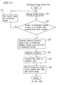
- Figure 5 is a flowchart illustrating a general procedure of a surveillance operation using the image surveillance apparatus of the present invention.
- the processing flow of the image surveillance apparatus of this embodiment is generally formed by four processing steps including a surveillance region setting step, a background image setting step, a surveillance step, and a background image update step.
- a surveillant sets a region in an image displayed on the display screen of the image output section 5 as a surveillance region by manipulating the manipulation section 4 (step S01).
- a plurality of regions can be surveilled by setting the plurality of regions as surveillance regions.
- step S02 After the setting of a certain surveillance region, setting processing for a background image is performed at the background image setting step (step S02).
- the surveillant who is surveilling the surveillance region, manipulates the manipulation section 4 , such that image data, which is obtained by the imaging section 1 , is stored in the background image storage region 15 of the storage section 3 ( Figure 3 ) by units of an image data segment having a frame number of N (one background image unit). Thereafter, updating of the background image unit is continued until the process proceeds to the surveillance step.
- step S03 it is determined whether the security mode of the image surveillance apparatus is ON or OFF. If the security mode is ON, the process transits from the background image setting step to the surveillance step. If the security mode is OFF, the process returns to the background image setting processing of step S02, and updating of the background image unit is continued.
- the frame number N is a plural number. However,- a basic image comparison operation can be performed even when the frame number N is 1.
- the transition from the background image setting step to the surveillance step is achieved by manipulation of the manipulation section 4 by the surveillant, who is surveilling the surveillance region, in a similar manner to that performed in transition from the surveillance region setting step to the background image setting step.
- the manipulation section 4 has an input switch for switching ON/OFF of the security mode of the image surveillance apparatus. This input switch is manipulated by the surveillant. Without a switch manipulation by the surveillance for turning the security mode ON, a transition instruction to the surveillance step is not issued, and the process returns to the background image setting step for updating the background image unit.
- surveillance processing is performed. Specifically, during surveillance processing, current image data of one frame is compared with the background image unit, whereby occurrence of an abnormal event, such as an intrusion of an intruder, is surveilled. Surveillance processing will be described later in more detail.
- the process proceeds to a security mode determination step where the control section 2 determines whether the security mode of the image surveillance apparatus is ON or OFF (step S05). If the security mode is OFF, the process proceeds to a stop processing determination step where the control section 2 determines whether or not a stop signal is issued for stopping the operation of the image surveillance apparatus (step S08). This stop signal is output to the control section 2 by, for example, a switch manipulation by the surveillant who is surveilling the surveillance region. If the stop signal is output to the control section 2, the power to the image surveillance apparatus is turned off, whereby the processing is ended.
- step S09 the control section 2 determines whether or not an instruction is issued for changing the surveillance region.
- an instruction for changing the surveillance region is issued by, for example, a switch manipulation by the surveillant who is surveilling the surveillance region. If the surveillance region change instruction is not issued, the process returns to the background image setting processing step of step S02. If the surveillance region change instruction is issued, the process returns to the surveillance region setting processing step of step S01.
- step S05 if the security mode is ON, the process proceeds to a background image update timing determination step where the control section 2 determines whether or not it is an appropriate time to update the background image unit (step S06). If the control section 2 determines that it is not an appropriate time to update the background image unit, the process returns to the surveillance step of step S04. If the control section 2 determines that it is an appropriate time to update the background image unit, the process proceeds to a background image updating step of step S07.
- step S07 background image updating processing is performed (step S07).
- the control section 2 refers to the time information of each background image which indicates the time when the background image was obtained and selects the oldest background image.
- the selected background image is updated to a new background image.
- the transition from the background image update processing step to the surveillance step is achieved by, for example, manipulation of the manipulation section 4 .
- An instruction signal generated by manipulation of the manipulation section 4 is output to the control section 2 .
- the control section 2 performs processing according to an instruction of the instruction signal.
- FIG. 6 is a flowchart which illustrates a general procedure of the surveillance region setting processing of step S01.
- step S01 at an image acquisition step, image data (captured data) of an image including a certain surveillance region which is captured by the imaging section 1 is stored in the current image storage region 16 of the storage section 3 through the control section 2 (step S11).
- this process is simply expressed in a sentence which reads "a current image is acquired from the imaging section 1".
- time information which indicates the time when the captured data was obtained, is stored in the current image storage region 16 of the storage section 3 together with the captured data.
- the obtained current image data is output from the control section 2 together with its time information to a monitor (not shown), which is provided together with a controller of an external device, through the image output section 5 .
- a surveillant who is observing the monitor sets a surveillance region in an image displayed on the monitor according to a surveillance region setting method (which will be described later), and the set surveillance region information is stored in the parameter storage region 14 of the storage section 3 .
- step S13 a message for asking the surveillant whether or not he/she wants to issue an instruction to add another surveillance region or change the surveillance region. If the surveillant wants to issue an instruction to add another surveillance region or change the surveillance region, the surveillant inputs such an instruction through the manipulation section 4 . The instruction input by the surveillant is transmitted to the control section 2 .
- the process returns to the current image acquisition step of step S11, where the surveillance region setting processing is continued by the surveillance region setting section 8. If an instruction to add another surveillance region or change the surveillance region is not issued, the process of Figure 6 proceeds to the background image setting processing at step S2 in the main flow of Figure 5 .
- Figure 7 schematically shows a circular captured image obtained by an omniazimuthal camera which is used as the imaging section 1 .
- First and second methods for setting a surveillance region are described below with reference to Figure 7 .
- a coordinate of the center of the surveillance region (e.g., A0 (r0, ⁇ 0)) is designated by a key entry through the manipulation section 4 .
- a predetermined area of region is set around the designated coordinate as a surveillance region.
- a hatched region represented by (r0 ⁇ r0, ⁇ 0 ⁇ 0) is designated as the surveillance region.
- r denotes a distance from a center O of the circular image to the coordinate (r, ⁇ )
- ⁇ denotes a central angle of the coordinate (r, ⁇ ) with respect to the center O of the circular image.
- coordinates corresponding to four corners of a certain region are designated by a key entry through the manipulation section 4 .
- the region defined by the four points is set as a surveillance region.
- the surveillance region can be set so as to have any extent of area.
- not only one surveillance region but also a plurality of surveillance regions can be set using the above first method and/or second method.
- Figure 8 schematically shows a captured image obtained by a CCD camera which is used as the imaging section 1 .
- a third method for setting a surveillance region is described below with reference to Figure 8 .
- a pair of surveillance regions are set such that they are symmetrical with respect to the center O of a circular coordinate system.
- distance r1 from the center O of the circular coordinate system, and two central angles ⁇ 1 and ⁇ 2 from a reference position in the circular image, four points, A1(r1, ⁇ 1), A2(r1, ⁇ 2), A3(r1,180°+ ⁇ 1)), A4(r1,180°+ ⁇ 2), can be selected.
- a first surveillance region defined by points A1(r1, ⁇ 1), B1(r2, ⁇ 5), B4(r2, ⁇ 8), and A4 (r1,180° + ⁇ 2), and a second surveillance region defined by points A2(r1, ⁇ 2), B2(r2, ⁇ 6), B3(r2, ⁇ 7), and A3(r1,180°+ ⁇ 1)), can be simultaneously set.
- all four points A2, B2, B1, and A1 are on a line. Further, all four points A3, B3, B4, and A4 are also on another line.
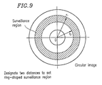
- Figure 9 schematically shows a circular captured image obtained by the imaging section 1 .
- a fourth method for setting a surveillance region is described below with reference to Figure 9 .
- a ring-shaped surveillance regions defined by a circle having diameter r1 and a circle having diameter r2 can be set.
- a region to be surveilled is a central area of a room, and an image surveillance apparatus of the present invention is installed above the region to be surveilled.
- the fourth method to set a ring-shaped surveillance region, and observing the set surveillance region, every possible approach and intrusion into the surveillance region can be detected regardless of the direction in which the intruder approaches or intrudes into surveillance region.
- the surveillance region can be set by simply designating two different distances. That is, the fourth method is advantageous in that the surveillance region can be set in a very easy manner.
- a coordinate(s) is designated by a key entry through the manipulation section 4 which is connected via a communication line to the control section 2 .
- a cursor key is slidden to a desired position, whereby a coordinate for defining a surveillance region can be designated.
- a coordinate can be designated by inputting coordinate parameters by a key entry operation.
- a touch panel formed over the monitor screen may be used as the manipulation section 4 . In such an arrangement, a coordinate can be designated by directly touching the touch panel over the monitor screen.
- a current image obtained by the imaging section 1 can be converted into a panoramic image or a perspective image by performing a key entry operation in the manipulation section 4 during the surveillance region setting processing.
- an instruction for image conversion is input through the manipulation section 4 and transmitted to the control section 2 .
- the control section 2 recognizes the instruction and transmits image conversion instruction information to the image conversion section 12 of the image processing section 6.
- the image conversion section 12 converts a current circular image into a panoramic image, perspective converted image, etc., based on the image conversion instruction information.
- the circular image is first converted to a panoramic image, for example.
- the surveillant can more easily grasp relative directions, and can readily set a desired surveillance region.
- a surveillant has repeatedly utilized the surveillance monitor screen and is now accustomed to observe a circular image, he/she would already have a good grasp of the relative positions in a circular image. In such a case, the surveillant can readily set a desired surveillance region in the circular image, and the efficiency in the surveillance region setting operation is higher than a case where the above image conversion is performed.
- Figure 10 schematically shows a panoramic image including a plurality of surveillance regions. Methods for setting a plurality of surveillance regions are described below with reference to Figure 10 .
- a predetermined area of region is set as the surveillance region.
- a distance from a reference point in the panoramic image is designated based on an angle from the reference point in the circular image, so as to set a surveillance region.
- surveillance regions are set by designating angular ranges ( ⁇ 1, ⁇ 2) and ( ⁇ 3, ⁇ 4), respectively.
- a desired position can be designated by using the manipulation section 4, such as a cursor key, a touch panel, or the like, in the same manner as that used in setting a surveillance region in a circular image.
- the positional information set for the surveillance region in this way is stored in the parameter storage region 14 of the storage section 3 .
- Amethod for converting a circular image as captured by the imaging section 1 into a panoramic image or a perspective converted image is described in detail in Japanese Patent Application No. 2000-152208, for example.
- a current image is obtained by the imaging section 1 (step S21).
- the obtained current image is stored in the current image storage region 16 of the storage section 3 .
- the current image data obtained by the imaging section 1 is stored in the current image storage region 16 of the storage section 3 together with time information which indicates the time when the current image data was obtained by the imaging section 1 .
- step S22 the control section 2 determines whether or not the number of background images stored in the background image storage region 15 of the storage section 3 (each background image having time information which indicates the time when the background image was captured by the imaging section 1 ) is equal to or greater than a predetermined number of frames (N frames). If the number of background images stored in the background image storage region 15 of the storage section 3 is smaller than N frames, the current image data obtained by the imaging section 1 at step S21 is stored as background image data in the background image storage region 15 of the storage section 3 (step S27). Then, the process returns to step S21.
- N frames a predetermined number of frames
- N frames a misdetection of occurrence of an abnormal event due to a variation in the background of an image which is caused within a short period of time.
- N frames a misdetection of occurrence of an abnormal event due to a variation in the background of an image which is caused within a short period of time.
- an abnormal signal may be sent to the control section 2.
- the background image unit (including N frames of background images) is updated at a predetermined time interval as described later. It should be noted that, in the case where the storage capacity of the storage section of the surveillance apparatus is small, or misdetection of occurrence of an abnormal event is small, the frame number of one background image unit may be 1.
- step S23 If the number of background images stored in the background image storage region 15 of the storage section 3 is equal to or greater than the predetermined number of frames (N frames) which consist one background image unit. The process proceeds to step S23.
- difference data of image is calculated by the image comparison section 10 based on differences between current image data (image data of 1 frame) and each of background image data included in a background image unit previously stored in the background image storage region 15 of the storage section 3. Then, in the image comparison section 10, the calculated difference image data is binarized using a certain threshold value stored in the parameter storage region 14 of the storage section 3 so as to obtain difference data of binarized image.
- the difference data of binarized image is temporarily stored in the difference image storage section 20 of the storage section 3 .
- the difference data of binarized image is obtained not for the entire view field range of an image obtained by the imaging section 1, but only for a preset surveillance region, in order to reduce the amount of calculation processing and thereby achieve a high processing speed. Furthermore, the threshold value used in binarization is set as a parameter by a surveillant by a key entry through the manipulation section 4 and stored in the parameter storage region 14 of the storage section 3 .
- step S24 based on the difference data of binarized image temporarily stored in the difference image storage section 20 of the storage section 3 , histogram data for each of X- and Y-directions of a X-Y matrix formatted over the difference data of binarized image is produced by the determination section 11 of the image processing section 6 by summing up image data values of the difference data of binarized image on respective coordinates over the X-Y matrix in each column and row of the X-Y matrix (hereinafter, this processing is referred to as "projection processing").
- the produced histogram data is stored in the histogram storage region 21 of the storage section 3 .
- Figure 14 schematically shows histogram data produced based on difference data of binarized image where a pixel arrangement is 5 ⁇ 5.
- each image value 24 in the 5 ⁇ 5 difference data of binarized image 23 is 0 or 1.
- the pixel value on each of coordinates (3,4), (1,3) to (4,3), and (2,2) to (2,3) is 1, whereas the pixel value on each of the other coordinates is 0.
- the histogram 26 along the X-direction is [1, 2, 3, 1, 0] from left to right
- the histogram 25 along the Y-direction is [0, 2, 4, 1, 0] upwardly. In this way, the projection processing is performed.
- step S24 After the projection processing at step S24 has been completed, the process proceeds to step S25 of Figure 11.
- step S25 among the histogram data produced by the projection processing at step S24, the maximum values of the respective histogram data are compared, and a background image corresponding to histogram data having the smallest maximum value is selected.
- the selected background image is sent to the background image registration section 9 , and the background image registration section 9 replaces the selected background image corresponding to histogram data having the smallest maximum value with current image data, and registers the replaced current image data as background image data (step S26).
- the maximum values of the respective extracted histogram data are compared for selecting background image data to be replaced with current image data.
- the total sums of the pixel values of the respective histogram data may be compared, and background image data having the smallest total sum value may be replaced with current image data.
- the background image setting processing is completed at the end of the processing at step S26, and the process flow returns to the main process flow shown in Figure 5.
- a current image (image data of 1 frame) is obtained by the imaging section 1 (step S31).
- the image comparison section 10 of the image processing section 6 the current image obtained by the imaging section 1 is compared, for each surveillance region, with each background image, included in a background image unit, previously stored in the background image storage region 15 of the storage section 3 , so as to obtain difference-binarized image data (step S32).
- the difference-binarized image data is stored in the difference image storage section 20 of the storage section 3 .
- binarization calculation is performed not for the entire view field range of an image obtained by the imaging section 1 , but only for a preset surveillance region, in order to reduce the amount of calculation processing and thereby achieve a high processing speed.
- the determination section 11 of the image processing section 6 performs projection processing for each surveillance region as described above (step S33).
- step S34 histogram data for the respective background images are summed up, and the summed-up result is stored in the histogram storage region 21 of the storage section 3 (step S34).
- step S35 the maximum value of the summed-up result stored in the histogram storage region 21 of the storage section 3 is calculated (step S35), and it is determined whether or not the calculated maximum value is greater than a threshold value (step S36).
- the threshold value used in this processing is input through the manipulation section 4 and stored in the parameter storage region 14 of the storage section 3 .
- step S36 If the maximum value is greater that the threshold (reference) value at step S36, it is determined that an abnormal event occurred.
- the process proceeds to step S37.
- step S37 an abnormal signal and information about a relevant surveillance region where the abnormal event occurred are transmitted to the control section 2 .
- the control section 2 outputs to the alarm output section 7 an alarm instruction together with the information about the relevant surveillance region.
- the alarm output section 7 outputs to an external device connected thereto an alarm message or alarm sound together with the information about the relevant surveillance region.
- an image conversion instruction is transmitted from the control section 2 to the image conversion section 12 of the image processing section 6 .
- the image conversion section 12 generates perspective converted image data such that a portion in the current image data which has the maximum value of the summed-up histogram data is positioned at the center of a X-Y coordinate system.
- the produced perspective converted image data is stored in the converted image storage region 17 of the storage section 3.
- the perspective converted image data stored in the converted image storage region 17 of the storage section 3 is output to the image output section 5 through the control section 2 .
- the image output section 5 transmits the perspective converted image data to a controller (not shown) operated by a surveillant, for example.
- the perspective converted image data is displayed on a monitor (not shown) provided together with the controller. After that, the process flow returns to the main process flow shown in Figure 5 .
- the determination section 11 determines that there is nothing to be examined, i.e., there is no abnormal event occurred, i.e., everything is normal in the surveillance region. In such a case, processing for outputting an alarm and a perspective converted image is not performed, and current image data is stored as a background image candidate in the background image candidate storage region 22 of the storage section 3. Thereafter, the process flow returns to the main process flow shown in Figure 5 .
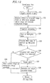
- the background image update processing of step S07 is begun if the control section 2 determines at step S06 of the main process flow shown in Figure 5 that it is an appropriate time to update a background image unit.
- This update timing occurs at a time when a certain time period has elapsed after a time when a background image was obtained.
- the certain time period is set to about 30 minutes to 1 hour, although it is influenced by a degree of variation in the background image. For example, consider a case where the image surveillance apparatus of the present invention is installed in a shop.
- the background image is not updated during a time period from a time when the shop is closed to a time when the shop is next opened. After the shop is opened, the background image is updated at a certain time interval.
- step S06 of Figure 5 determines at step S06 of Figure 5 that it is a predetermined time to update the background image
- the background image update processing of step S07 is begun and then carried out according to the flow shown in Figure 13 .
- a background image candidate which has been stored in the background image candidate storage region 22 of the storage section 3 when it is determined at step S04 ( Figure 5 ) that there is no abnormal event occurred, is read out into the background image registration section 9 of the image processing section 6 (step S41).
- step S42 it is determined, based on time information attached to respective image data stored in the background image storage region 15 of the storage section 3 , that there is old background image data which has been aged for a certain time period or more in the background image registration section 9 .
- step S42 If there is old background image data which has been aged for a certain time period or more ("Y" at step S42), the process proceeds to step S47.
- the old background image data which has been aged for a certain time period or more is deleted, and the background image candidate read out at step S41 is set as new background image data. If a plurality of background image data which has been aged for a certain time period or more are found, the oldest one of them is selected and replaced with the background image candidate.
- step S42 If no background image satisfies such a criteria ("N" at step S42), the process proceeds to step S43.
- the image comparison section 10 of the image processing section 6 produces difference-binarized image data based on differences between the background image candidate and each of the background image data.
- the produced difference-binarized image data is stored in the difference image storage section 20 of the storage section 3 .
- step S44 projection processing is performed on each of the difference-binarized image data stored in the difference image storage section 20 of the storage section 3 , so as to produce histogram data.
- the produced histogram data is stored in the histogram storage region 21 of the storage section 3 .
- step S45 among the histogram data produced by the projection processing at step S44, the maximum values of the respective histogram data are compared.
- a background image corresponding to histogram data having the smallest maximum value is selected, and this selected background image is replaced with the background image candidate (step S46).
- any desired region in an omniazimuthal view field image obtained by an omniazimuthal camera of the image surveillance apparatus can be set as a surveillance region.
- image conversion can be performed in a smooth manner so that a perspective converted image or the like is obtained.
- a plurality of background images for comparison with a current image is provided.
- An image surveillance apparatus of the present invention includes an imaging section which has a convex mirror having a shape of a body of rotation and is capable of obtaining an image from a 360° (omniazimuthal) view field area. Only with a single imaging section having such a structure, a plurality of regions, each of which is present in any direction seen from the imaging section, and which is defined by any shape of boundary line, can be set as surveillance regions . Thus , it is not necessary to provide a plurality of surveillance apparatuses, or to provide a driving mechanism for moving the imaging section for the purpose of obtaining an image from any desired direction. Without such an additional arrangement, the surveillance apparatus of the present invention can monitor a wide range of surveillance region(s).
- an image processing section performs image conversion so as to generate a perspective converted image including the object to be examined.
- a perspective image With such a perspective image, the object can be examined readily and smoothly. Further still, since detection of an abnormal event is performed based on a comparison between a plurality of background images and a current image, an undesired influence caused by a variation in the backgrounds of the images is reduced, and accordingly, detection accuracy for detecting an object to be examined is improved.
Abstract
Description
Claims (17)
- An image surveillance apparatus, comprising:an imaging section including a convex mirror having a shape of a body of rotation, the imaging section obtaining an image of an omniazimuthal region and generating image data of the omniazimuthal region;a surveillance region setting section for setting a surveillance region in the image data of the omniazimuthal region which is obtained from the imaging section;an image processing section for performing image processing according to determination information obtained from a comparison/determination between background image data obtained by the imaging section in advance, which is used as a reference that represents a normal state of the surveillance region, and current image data obtained by the imaging section at a predetermined time interval; anda surveillance information output section for outputting surveillance information according to the determination information.
- An image surveillance apparatus according to claim 1, wherein the surveillance information output section is an image output section.
- An image surveillance apparatus according to claim 1, wherein the image processing section includes:an image comparison section for comparing the background image data and the current image data;a determination section for determining the presence/absence of an object to be examined based on a comparison result of the image comparison section; andan image conversion section for performing certain image conversion processing based on the determination result of the determination section.
- An image surveillance apparatus according to claim 1, wherein the surveillance region setting section sets a plurality of surveillance regions.
- An image surveillance apparatus according to claim 1, wherein the image processing section converts the image data of the omniazimuthal region, which is obtained by the imaging section, into panoramic image data or perspective converted image data.
- An image surveillance apparatus according to claim 1, further comprising an alarm information output section for outputting alarm information when the image processing section determines that the current image data is different from the background image data.
- An image surveillance apparatus according to claim 3, wherein:the image comparison section generates comparison result image data based on a difference between the background image data and the current image data; andthe determination section performs projection processing based on a comparison result for each surveillance region.
- An image surveillance apparatus according to claim 1, wherein time information, which indicates the time when the background image data was obtained, is attached to the background image data.
- An image surveillance apparatus according to claim 1, wherein:the image data obtained by the imaging section is circular image data; andthe surveillance region is set based on a polar coordinate system where a center of the circular image data is an origin of the system.
- An image surveillance apparatus according to claim 1, wherein:the image data obtained by the imaging section is circular image data; anda ring-shaped region is set as the surveillance region by designating two distances from a center of the circular image data.
- An image surveillance apparatus according to claim 1, wherein:the image data obtained by the imaging section is circular image data; anda pair of symmetric regions are set as the surveillance regions by designating two distances from a center of the circular image data and two central angles.
- An image surveillance method using an imaging section which includes a convex mirror having a shape of a body of rotation, the imaging section obtaining an image of an omniazimuthal region, comprising:a surveillance region setting step of setting a desired surveillance region in omniazimuthal image data obtained by the imaging section;a background image setting step of setting a plurality of image data obtained by the imaging section as background image data which are used as a reference that represent a normal state of the surveillance region; anda surveillance step of surveilling the presence/absence of an abnormal event in the surveillance region based on a comparison result between the plurality of background image data and current image data obtained by the imaging section at a predetermined time interval.
- An image surveillance method according to claim 12, further comprising a background image update step of updating the background image data when a predetermined time has elapsed after the setting of the background image data based on the predetermined elapsed time.
- An image surveillance method according to claim 13, wherein the surveillance step includes:a difference-binarized image generation step of acquiring the current image data obtained at a predetermined time interval, and generating difference-binarized image data based on a comparison performed for each surveillance region between the current image data and the background image data;a projection step of performing projection processing on the difference-binarized image data for each surveillance region;a maximum value calculation step of summing up data obtained by the projection processing and calculating a maximum value of the summed-up result;a determination step of determining whether or not the calculated maximum value is greater than a predetermined threshold value; andan alarming step of outputting at least an alarm or converted image data produced from current image data in a certain region when it is determined that the calculated maximum value is greater than the predetermined threshold value.
- An image surveillance method according to claim 13, further comprising a storage step of storing the current image data as a background image candidate in a storage section when it is determined in the determination step that the calculated maximum value is not greater than the predetermined threshold value.
- An image surveillance processing program for executing the image surveillance method recited in claim 12.
- A surveillance system using an omniazimuthal image detection device for capturing image data in a predetermined surveillance region, and a control unit which repeatedly compares current said image data with prestored background image data representing a normal state of the surveillance region.
Applications Claiming Priority (2)
| Application Number | Priority Date | Filing Date | Title |
|---|---|---|---|
| JP2001177810 | 2001-06-12 | ||
| JP2001177810A JP3698420B2 (en) | 2001-06-12 | 2001-06-12 | Image monitoring apparatus, image monitoring method, and image monitoring processing program |
Publications (3)
| Publication Number | Publication Date |
|---|---|
| EP1267313A2 true EP1267313A2 (en) | 2002-12-18 |
| EP1267313A3 EP1267313A3 (en) | 2003-10-15 |
| EP1267313B1 EP1267313B1 (en) | 2006-08-09 |
Family
ID=19018600
Family Applications (1)
| Application Number | Title | Priority Date | Filing Date |
|---|---|---|---|
| EP02254066A Expired - Lifetime EP1267313B1 (en) | 2001-06-12 | 2002-06-11 | Image surveillance apparatus, image surveillance method, and image surveillance processing program |
Country Status (6)
| Country | Link |
|---|---|
| US (1) | US7260241B2 (en) |
| EP (1) | EP1267313B1 (en) |
| JP (1) | JP3698420B2 (en) |
| KR (1) | KR100634237B1 (en) |
| CN (1) | CN1201585C (en) |
| DE (1) | DE60213715T2 (en) |
Cited By (3)
| Publication number | Priority date | Publication date | Assignee | Title |
|---|---|---|---|---|
| FR2944934A1 (en) * | 2009-04-27 | 2010-10-29 | Scutum | Sites monitoring method for communication network, involves initially modifying video stream by integration of reference elements adapted to scenic contents of each image in order to identify causes of event |
| US20140009571A1 (en) * | 2006-11-23 | 2014-01-09 | Zheng Jason Geng | Wide Field of View Reflector and Method of Designing and Making Same |
| WO2021059139A1 (en) * | 2019-09-27 | 2021-04-01 | Ricoh Company, Ltd. | Apparatus, image processing system, communication system, method for setting, image processing method, and recording medium |
Families Citing this family (48)
| Publication number | Priority date | Publication date | Assignee | Title |
|---|---|---|---|---|
| US6701005B1 (en) | 2000-04-29 | 2004-03-02 | Cognex Corporation | Method and apparatus for three-dimensional object segmentation |
| US20030234863A1 (en) * | 2002-06-19 | 2003-12-25 | Chin-Hsin Yang | Environmental change auto-detection digital camera |
| US7920718B2 (en) | 2002-09-05 | 2011-04-05 | Cognex Corporation | Multi-zone passageway monitoring system and method |
| AU2003901532A0 (en) * | 2003-04-04 | 2003-05-01 | Evolution Broadcast Pty Limited | Broadcast control |
| KR100481538B1 (en) * | 2003-05-19 | 2005-04-07 | 삼성전자주식회사 | Apparatus and method for detecting change in background area |
| US7956889B2 (en) * | 2003-06-04 | 2011-06-07 | Model Software Corporation | Video surveillance system |
| US8326084B1 (en) | 2003-11-05 | 2012-12-04 | Cognex Technology And Investment Corporation | System and method of auto-exposure control for image acquisition hardware using three dimensional information |
| US7623674B2 (en) * | 2003-11-05 | 2009-11-24 | Cognex Technology And Investment Corporation | Method and system for enhanced portal security through stereoscopy |
| JP2005159691A (en) * | 2003-11-26 | 2005-06-16 | Hitachi Ltd | Supervisory system |
| JP2006025007A (en) * | 2004-07-06 | 2006-01-26 | Fuji Photo Film Co Ltd | Image processor and image processing program |
| US7366359B1 (en) * | 2004-07-08 | 2008-04-29 | Grandeye, Ltd. | Image processing of regions in a wide angle video camera |
| US8132225B2 (en) | 2004-09-30 | 2012-03-06 | Rockwell Automation Technologies, Inc. | Scalable and flexible information security for industrial automation |
| US8111904B2 (en) | 2005-10-07 | 2012-02-07 | Cognex Technology And Investment Corp. | Methods and apparatus for practical 3D vision system |
| JP2008028606A (en) * | 2006-07-20 | 2008-02-07 | Opt Kk | Imaging device and imaging system for panoramically expanded image |
| DE102007024868A1 (en) * | 2006-07-21 | 2008-01-24 | Robert Bosch Gmbh | Image processing apparatus, monitoring system, method for generating a scene reference image and computer program |
| TW200811749A (en) * | 2006-08-17 | 2008-03-01 | Inventec Corp | System and method for setting image-monitoring region |
| US8072482B2 (en) | 2006-11-09 | 2011-12-06 | Innovative Signal Anlysis | Imaging system having a rotatable image-directing device |
| JP4795212B2 (en) * | 2006-12-05 | 2011-10-19 | キヤノン株式会社 | Recording device, terminal device, and processing method |
| JP4318724B2 (en) | 2007-02-14 | 2009-08-26 | パナソニック株式会社 | Surveillance camera and surveillance camera control method |
| US8126260B2 (en) | 2007-05-29 | 2012-02-28 | Cognex Corporation | System and method for locating a three-dimensional object using machine vision |
| US9380256B2 (en) * | 2007-06-04 | 2016-06-28 | Trover Group Inc. | Method and apparatus for segmented video compression |
| JP4636130B2 (en) * | 2008-06-27 | 2011-02-23 | ソニー株式会社 | Image processing apparatus, imaging apparatus, image processing method, and program |
| JP5045590B2 (en) * | 2008-07-23 | 2012-10-10 | 三菱電機株式会社 | Display device |
| JP5550293B2 (en) | 2009-09-18 | 2014-07-16 | キヤノン株式会社 | Image collation system, imaging device, transmission device, and program |
| EP2302564A1 (en) * | 2009-09-23 | 2011-03-30 | Iee International Electronics & Engineering S.A. | Real-time dynamic reference image generation for range imaging system |
| CN102056032B (en) * | 2009-11-05 | 2013-06-05 | 中兴通讯股份有限公司 | Device and method for multi-standard data transmission based on OBSAI protocol |
| US9430923B2 (en) | 2009-11-30 | 2016-08-30 | Innovative Signal Analysis, Inc. | Moving object detection, tracking, and displaying systems |
| JP5090496B2 (en) | 2010-04-12 | 2012-12-05 | 住友重機械工業株式会社 | Image generating apparatus and operation support system |
| JP5495930B2 (en) | 2010-05-10 | 2014-05-21 | キヤノン株式会社 | Image processing apparatus, method, and program |
| JP5589644B2 (en) * | 2010-07-27 | 2014-09-17 | 日本精機株式会社 | Peripheral image display device and display method thereof |
| JP2012029180A (en) * | 2010-07-27 | 2012-02-09 | Nippon Seiki Co Ltd | Peripheral image display device and display method thereof |
| JP5739722B2 (en) * | 2011-04-26 | 2015-06-24 | 株式会社日立情報通信エンジニアリング | Object recognition method and recognition apparatus |
| CN103192414B (en) * | 2012-01-06 | 2015-06-03 | 沈阳新松机器人自动化股份有限公司 | Robot anti-collision protection device and method based on machine vision |
| US8615110B2 (en) * | 2012-03-01 | 2013-12-24 | Herzog Railroad Services, Inc. | Automated track surveying and ditching |
| CN102695044B (en) * | 2012-06-08 | 2015-04-15 | 杭州海康威视数字技术股份有限公司 | Method and system for capturing partial graph by using video camera |
| CN103871186A (en) * | 2012-12-17 | 2014-06-18 | 博立码杰通讯(深圳)有限公司 | Security and protection monitoring system and corresponding warning triggering method |
| JP2014143678A (en) * | 2012-12-27 | 2014-08-07 | Panasonic Corp | Voice processing system and voice processing method |
| WO2014118872A1 (en) | 2013-01-29 | 2014-08-07 | 有限会社ラムロック映像技術研究所 | Monitor system |
| US9544511B2 (en) | 2013-03-15 | 2017-01-10 | International Business Machines Corporation | Large-area monitoring using infrared imaging system |
| US9508115B2 (en) | 2013-03-15 | 2016-11-29 | International Business Machines Corporation | Large-area monitoring using infrared imaging system |
| TWI493477B (en) * | 2013-09-06 | 2015-07-21 | Utechzone Co Ltd | Method for detecting the status of a plurality of people and a computer-readable storing medium and visual monitoring device thereof |
| CN105334543B (en) * | 2014-05-26 | 2017-12-01 | 北京维森科技有限公司 | Detection method and device be present in the human body compared based on infrared triggering image |
| US10139819B2 (en) | 2014-08-22 | 2018-11-27 | Innovative Signal Analysis, Inc. | Video enabled inspection using unmanned aerial vehicles |
| KR102128319B1 (en) * | 2014-10-24 | 2020-07-09 | 에스케이 텔레콤주식회사 | Method and Apparatus for Playing Video by Using Pan-Tilt-Zoom Camera |
| US10909384B2 (en) | 2015-07-14 | 2021-02-02 | Panasonic Intellectual Property Management Co., Ltd. | Monitoring system and monitoring method |
| CN106446797B (en) * | 2016-08-31 | 2019-05-07 | 腾讯科技(深圳)有限公司 | Image clustering method and device |
| JP6727998B2 (en) * | 2016-09-08 | 2020-07-22 | キヤノン株式会社 | Image processing apparatus, image processing method and program |
| CN112019960A (en) * | 2019-05-28 | 2020-12-01 | 深圳市冠旭电子股份有限公司 | Method for monitoring scenes by utilizing earphone, device and readable storage medium |
Citations (5)
| Publication number | Priority date | Publication date | Assignee | Title |
|---|---|---|---|---|
| US4679077A (en) * | 1984-11-10 | 1987-07-07 | Matsushita Electric Works, Ltd. | Visual Image sensor system |
| US5243418A (en) * | 1990-11-27 | 1993-09-07 | Kabushiki Kaisha Toshiba | Display monitoring system for detecting and tracking an intruder in a monitor area |
| US5455561A (en) * | 1994-08-02 | 1995-10-03 | Brown; Russell R. | Automatic security monitor reporter |
| US5790181A (en) * | 1993-08-25 | 1998-08-04 | Australian National University | Panoramic surveillance system |
| US6215519B1 (en) * | 1998-03-04 | 2001-04-10 | The Trustees Of Columbia University In The City Of New York | Combined wide angle and narrow angle imaging system and method for surveillance and monitoring |
Family Cites Families (19)
| Publication number | Priority date | Publication date | Assignee | Title |
|---|---|---|---|---|
| US3823261A (en) * | 1968-05-27 | 1974-07-09 | E Bolsey | Image motion and change transducers and systems controlled thereby |
| JPS56160183A (en) * | 1980-05-09 | 1981-12-09 | Hajime Sangyo Kk | Method and device for monitoring |
| DE3720489A1 (en) * | 1987-06-20 | 1988-12-29 | Sood Ralf A | METHOD FOR READING TEXT AND PRINT ORIGINALS |
| JP2758282B2 (en) | 1991-05-02 | 1998-05-28 | 三菱電機株式会社 | Image monitoring device |
| US6243131B1 (en) * | 1991-05-13 | 2001-06-05 | Interactive Pictures Corporation | Method for directly scanning a rectilinear imaging element using a non-linear scan |
| US5185667A (en) * | 1991-05-13 | 1993-02-09 | Telerobotics International, Inc. | Omniview motionless camera orientation system |
| JPH07262355A (en) | 1994-03-18 | 1995-10-13 | Fuji Electric Co Ltd | Image monitoring device |
| JP3048896B2 (en) | 1995-08-11 | 2000-06-05 | 東京電力株式会社 | Noise removal filter device for binary image |
| JPH10117338A (en) | 1996-10-09 | 1998-05-06 | Nippon Lsi Card Kk | Monitoring device |
| DE69921237T2 (en) | 1998-04-30 | 2006-02-02 | Texas Instruments Inc., Dallas | Automatic video surveillance system |
| JP2000253310A (en) | 1998-07-21 | 2000-09-14 | Canon Inc | Image processor, its method, storage medium and its system |
| JP2000059758A (en) * | 1998-08-05 | 2000-02-25 | Matsushita Electric Ind Co Ltd | Monitoring camera apparatus, monitoring device and remote monitor system using them |
| JP3965003B2 (en) | 1999-06-01 | 2007-08-22 | セコム株式会社 | Image recognition device and monitoring device |
| JP2001114045A (en) | 1999-10-15 | 2001-04-24 | Furukawa Co Ltd | Surrounding monitor |
| JP3907891B2 (en) * | 1999-11-11 | 2007-04-18 | 富士フイルム株式会社 | Image capturing apparatus and image processing apparatus |
| US6707486B1 (en) * | 1999-12-15 | 2004-03-16 | Advanced Technology Video, Inc. | Directional motion estimator |
| US20010052933A1 (en) * | 2000-01-12 | 2001-12-20 | Nybo Larry Carl | System and method for image capture, storage and retrieval |
| CA2313803A1 (en) * | 2000-07-11 | 2002-01-11 | Dong-Chan He | Automatic extraction of linear features from digital imagery |
| US7257235B2 (en) * | 2002-02-28 | 2007-08-14 | Minolta Co., Ltd. | Monitoring apparatus, monitoring method, monitoring program and monitoring program recorded recording medium readable by computer |
-
2001
- 2001-06-12 JP JP2001177810A patent/JP3698420B2/en not_active Expired - Fee Related
-
2002
- 2002-06-11 US US10/167,258 patent/US7260241B2/en not_active Expired - Fee Related
- 2002-06-11 EP EP02254066A patent/EP1267313B1/en not_active Expired - Lifetime
- 2002-06-11 DE DE60213715T patent/DE60213715T2/en not_active Expired - Lifetime
- 2002-06-12 CN CNB021275580A patent/CN1201585C/en not_active Expired - Fee Related
- 2002-06-12 KR KR1020020032817A patent/KR100634237B1/en not_active IP Right Cessation
Patent Citations (5)
| Publication number | Priority date | Publication date | Assignee | Title |
|---|---|---|---|---|
| US4679077A (en) * | 1984-11-10 | 1987-07-07 | Matsushita Electric Works, Ltd. | Visual Image sensor system |
| US5243418A (en) * | 1990-11-27 | 1993-09-07 | Kabushiki Kaisha Toshiba | Display monitoring system for detecting and tracking an intruder in a monitor area |
| US5790181A (en) * | 1993-08-25 | 1998-08-04 | Australian National University | Panoramic surveillance system |
| US5455561A (en) * | 1994-08-02 | 1995-10-03 | Brown; Russell R. | Automatic security monitor reporter |
| US6215519B1 (en) * | 1998-03-04 | 2001-04-10 | The Trustees Of Columbia University In The City Of New York | Combined wide angle and narrow angle imaging system and method for surveillance and monitoring |
Cited By (3)
| Publication number | Priority date | Publication date | Assignee | Title |
|---|---|---|---|---|
| US20140009571A1 (en) * | 2006-11-23 | 2014-01-09 | Zheng Jason Geng | Wide Field of View Reflector and Method of Designing and Making Same |
| FR2944934A1 (en) * | 2009-04-27 | 2010-10-29 | Scutum | Sites monitoring method for communication network, involves initially modifying video stream by integration of reference elements adapted to scenic contents of each image in order to identify causes of event |
| WO2021059139A1 (en) * | 2019-09-27 | 2021-04-01 | Ricoh Company, Ltd. | Apparatus, image processing system, communication system, method for setting, image processing method, and recording medium |
Also Published As
| Publication number | Publication date |
|---|---|
| KR100634237B1 (en) | 2006-10-17 |
| CN1201585C (en) | 2005-05-11 |
| KR20020094915A (en) | 2002-12-18 |
| US20020196962A1 (en) | 2002-12-26 |
| EP1267313A3 (en) | 2003-10-15 |
| JP3698420B2 (en) | 2005-09-21 |
| DE60213715D1 (en) | 2006-09-21 |
| EP1267313B1 (en) | 2006-08-09 |
| JP2002374519A (en) | 2002-12-26 |
| US7260241B2 (en) | 2007-08-21 |
| CN1391404A (en) | 2003-01-15 |
| DE60213715T2 (en) | 2007-08-16 |
Similar Documents
| Publication | Publication Date | Title |
|---|---|---|
| EP1267313B1 (en) | Image surveillance apparatus, image surveillance method, and image surveillance processing program | |
| US10861304B2 (en) | Monitoring camera and monitoring camera control method | |
| US9041800B2 (en) | Confined motion detection for pan-tilt cameras employing motion detection and autonomous motion tracking | |
| US7596240B2 (en) | Object tracking method and object tracking apparatus | |
| KR100432870B1 (en) | Intruding object monitoring method and intruding object monitoring system | |
| US20130021433A1 (en) | Overview configuration and control method for ptz cameras | |
| US20060170772A1 (en) | Surveillance system and method | |
| JP2006523043A (en) | Method and system for monitoring | |
| US20030202102A1 (en) | Monitoring system | |
| JP4475164B2 (en) | Monitoring system and monitoring method | |
| JP2014194687A (en) | Monitoring device | |
| KR101442669B1 (en) | Method and apparatus for criminal acts distinction using intelligent object sensing | |
| JP2005102392A (en) | Arc monitoring system | |
| JPH1169342A (en) | Image processing system for tracking intruding object | |
| KR20010016639A (en) | Surveillance System using an Omni-directional Camera and Multiple Pan·Tilt·Zoom Cameras and Controlling Method therefore | |
| JP3770180B2 (en) | Object monitoring device | |
| JP4171310B2 (en) | Intruder detection method and intruder detection apparatus | |
| JP2001245284A (en) | Method and system for supervising intruding object | |
| JPH0793558A (en) | Image monitoring device | |
| JP2005057743A (en) | Object tracking method and object tracking apparatus | |
| JP2019205034A (en) | Monitor parameter update system, monitor parameter update method and program | |
| JP3995832B2 (en) | Image sensor | |
| JP2000224457A (en) | Monitoring system, control method therefor and storage medium storing program therefor | |
| JP2002042272A (en) | Monitor, monitoring method, and record medium readable of computer recording monitor program | |
| JP3846553B2 (en) | Image processing device |
Legal Events
| Date | Code | Title | Description |
|---|---|---|---|
| PUAI | Public reference made under article 153(3) epc to a published international application that has entered the european phase |
Free format text: ORIGINAL CODE: 0009012 |
|
| AK | Designated contracting states |
Kind code of ref document: A2 Designated state(s): AT BE CH CY DE DK ES FI FR GB GR IE IT LI LU MC NL PT SE TR |
|
| AX | Request for extension of the european patent |
Free format text: AL;LT;LV;MK;RO;SI |
|
| PUAL | Search report despatched |
Free format text: ORIGINAL CODE: 0009013 |
|
| AK | Designated contracting states |
Kind code of ref document: A3 Designated state(s): AT BE CH CY DE DK ES FI FR GB GR IE IT LI LU MC NL PT SE TR |
|
| AX | Request for extension of the european patent |
Extension state: AL LT LV MK RO SI |
|
| RIC1 | Information provided on ipc code assigned before grant |
Ipc: 7G 08B 13/196 B Ipc: 7G 08B 13/194 A |
|
| 17P | Request for examination filed |
Effective date: 20040407 |
|
| AKX | Designation fees paid |
Designated state(s): DE FR GB |
|
| 17Q | First examination report despatched |
Effective date: 20040819 |
|
| GRAP | Despatch of communication of intention to grant a patent |
Free format text: ORIGINAL CODE: EPIDOSNIGR1 |
|
| GRAS | Grant fee paid |
Free format text: ORIGINAL CODE: EPIDOSNIGR3 |
|
| GRAA | (expected) grant |
Free format text: ORIGINAL CODE: 0009210 |
|
| AK | Designated contracting states |
Kind code of ref document: B1 Designated state(s): DE FR GB |
|
| REG | Reference to a national code |
Ref country code: GB Ref legal event code: FG4D |
|
| REF | Corresponds to: |
Ref document number: 60213715 Country of ref document: DE Date of ref document: 20060921 Kind code of ref document: P |
|
| ET | Fr: translation filed | ||
| PLBE | No opposition filed within time limit |
Free format text: ORIGINAL CODE: 0009261 |
|
| STAA | Information on the status of an ep patent application or granted ep patent |
Free format text: STATUS: NO OPPOSITION FILED WITHIN TIME LIMIT |
|
| 26N | No opposition filed |
Effective date: 20070510 |
|
| PGFP | Annual fee paid to national office [announced via postgrant information from national office to epo] |
Ref country code: FR Payment date: 20100709 Year of fee payment: 9 |
|
| PGFP | Annual fee paid to national office [announced via postgrant information from national office to epo] |
Ref country code: DE Payment date: 20100610 Year of fee payment: 9 Ref country code: GB Payment date: 20100609 Year of fee payment: 9 |
|
| GBPC | Gb: european patent ceased through non-payment of renewal fee |
Effective date: 20110611 |
|
| REG | Reference to a national code |
Ref country code: FR Ref legal event code: ST Effective date: 20120229 |
|
| REG | Reference to a national code |
Ref country code: DE Ref legal event code: R119 Ref document number: 60213715 Country of ref document: DE Effective date: 20120103 |
|
| PG25 | Lapsed in a contracting state [announced via postgrant information from national office to epo] |
Ref country code: DE Free format text: LAPSE BECAUSE OF NON-PAYMENT OF DUE FEES Effective date: 20120103 Ref country code: FR Free format text: LAPSE BECAUSE OF NON-PAYMENT OF DUE FEES Effective date: 20110630 |
|
| PG25 | Lapsed in a contracting state [announced via postgrant information from national office to epo] |
Ref country code: GB Free format text: LAPSE BECAUSE OF NON-PAYMENT OF DUE FEES Effective date: 20110611 |