EP1269745B2 - Method and system for combining multi-spectral images - Google Patents
Method and system for combining multi-spectral images Download PDFInfo
- Publication number
- EP1269745B2 EP1269745B2 EP01920117.7A EP01920117A EP1269745B2 EP 1269745 B2 EP1269745 B2 EP 1269745B2 EP 01920117 A EP01920117 A EP 01920117A EP 1269745 B2 EP1269745 B2 EP 1269745B2
- Authority
- EP
- European Patent Office
- Prior art keywords
- image
- scene
- spectral
- spectral band
- images
- Prior art date
- Legal status (The legal status is an assumption and is not a legal conclusion. Google has not performed a legal analysis and makes no representation as to the accuracy of the status listed.)
- Expired - Lifetime
Links
Images
Classifications
-
- G—PHYSICS
- G02—OPTICS
- G02B—OPTICAL ELEMENTS, SYSTEMS OR APPARATUS
- G02B23/00—Telescopes, e.g. binoculars; Periscopes; Instruments for viewing the inside of hollow bodies; Viewfinders; Optical aiming or sighting devices
- G02B23/12—Telescopes, e.g. binoculars; Periscopes; Instruments for viewing the inside of hollow bodies; Viewfinders; Optical aiming or sighting devices with means for image conversion or intensification
-
- H—ELECTRICITY
- H04—ELECTRIC COMMUNICATION TECHNIQUE
- H04N—PICTORIAL COMMUNICATION, e.g. TELEVISION
- H04N23/00—Cameras or camera modules comprising electronic image sensors; Control thereof
- H04N23/10—Cameras or camera modules comprising electronic image sensors; Control thereof for generating image signals from different wavelengths
- H04N23/11—Cameras or camera modules comprising electronic image sensors; Control thereof for generating image signals from different wavelengths for generating image signals from visible and infrared light wavelengths
-
- H—ELECTRICITY
- H04—ELECTRIC COMMUNICATION TECHNIQUE
- H04N—PICTORIAL COMMUNICATION, e.g. TELEVISION
- H04N5/00—Details of television systems
- H04N5/30—Transforming light or analogous information into electric information
- H04N5/33—Transforming infrared radiation
Description
- This invention relates generally to the field of electro-optics and, more specifically, to a method and system for combining multi-spectral images of a scene.
- Various systems are known for displaying visual images of a scene using electromagnetic radiation of a specific spectral region or band. For instance, infrared (IR) devices are employed in numerous applications for both civilian and military purposes. It is also known to observe a scene in an extreme low light environment using light amplification or intensification such as night vision equipment employing image intensifier technology. An example of a night vision device is the night vision goggle designated by the U.S. military as an AN/PVS-7. Another night vision device is described in
U.S. Patent No. 4,463,252 . Different devices are needed for displaying scenes in different spectral ranges or bands because different information is conveyed through the different spectra. While various techniques have been employed to combine multi-spectral images of a single scene, they share various disadvantages and deficiencies. - One technique known for combining an infrared image with an image displayed at visible wavelengths is described in
U.S. Patent No. 4,751,571 to Lillquist . The system disclosed in this patent has two separate image paths. One path transmits visible light to an image intensifier while a second path transmits thermal IR to an IR detector. Both the intensified image and the IR image are converted to electronic video signals. The two electronic signals are then mixed at a video mixer and then displayed on a color monitor. The technique described in the Lillquist patent has the disadvantage of requiring that both signals be electronically converted and electronically combined before being displayed to a user. Such electronic conversion will loose the very high resolution of the night vision device. Additionally, the Lillquist approach requires a dedicated system not usable with the vast population of existing night vision devices. - Another image fusion system is described in
U.S. Patent No. 5,035,472 to Hansen . This patent describes a device that conveys the image along two separate paths. One path directs the image to an IR detector which produces an IR image. The IR image is then transmitted to a CRT which displays the image. A second path directs the image of the scene to an image intensifier tube which generates an intensified image which also produces a visual display of the image. The displayed IR and intensified images are optically combined for display to a user. The technique described in the Hansen patent requires both images to be visibly generated before they are optically combined behind the image intensifier. This approach has the disadvantage of requiring a dedicated system not usable with the vast population of existing night vision devices. - Another technique calls for detecting a scene using multiple sensors which convert the images to digital data and then algorithmically combine the data using microelectronic processors. The disadvantages of this approach are that it is time consuming, requires substantial processing power, and the high resolution of a night vision channel cannot be captured electronically.
- All of these techniques suffer from the primary disadvantage of not being capable of use with pre-existing direct view devices. For instance, none of these devices is capable of operation with existing night vision equipment.
- While these devices and methods have provided a significant improvement over prior approaches, the challenges in the field of electro-optics has continued to increase with demands for more and better techniques having greater flexibility and adaptability. Therefore, a need has arisen for a new modular method for combining multi-spectral images of a scene.
- Further information pertaining to the prior art can be found in
US patent 5,035,472 which has been interpreted by the European Patent Office as explicitly disclosing a system for combining multi-spectral images of a scene, the system comprising a channel for transmitting a scene image in a first spectral band, a detector for sensing the scene in a second spectral band, the detector having an image output representative of the scene, a display for receiving the image output and displaying a displayed image in the first spectral band, and a beam mixer (118; 422) for combining the transmitted scene in the first spectral band with the displayed image and conveying the combined multi-spectral images to an output. - The present invention provides system for combining multi-spectral images of a scene in accordance with independent claim 1 as well as a method for combining multi-spectral images of a scene in accordance with independent claim 13. Preferred embodiments of the invention are reflected in the dependent claims.
- In accordance with the present invention, a method and system for combining multi-spectral images of a scene is provided that substantially eliminates or reduces disadvantages and problems associated with previously developed systems and methods. Multi-spectral is defined in this disclosure as two or more separate sensors with distinct response to an assigned spectral region. These regions may be completely different without any overlap, or very similar with virtually complete overlap, or anything else in-between.
- A system for combining multi-spectral images of a scene is disclosed. The system comprises the features of claim 1. There is a detector for sensing the scene in a second spectral band, this detector has an image output representative of the viewed scene. A display for receiving the representative image output and visibly displaying a displayed image in the first spectral band is provided. There is a collimator for receiving and projecting the displayed image. A beam mixer is provided for combining both the transmitted scene in the first spectral band with the displayed image and conveying the combined multi-spectral image to an output.
- The system also has an intensifier system for viewing the scene in the first spectral band. The intensifier system has an objective lens, an image intensifier and viewing optics. In this embodiment, the combined multi-spectral image is conveyed through the output to the intensifier system to display the combined multi-spectral images of the scene.
- A method for combining multi-spectral images of a scene is disclosed. The method comprises the steps according to claim 13. Step one calls for receiving an image of the scene in a secondary spectral range at a detector. Step two requires generating a video representation of the image.
- Step three provides transmitting the video representation to a display. In step four, the method provides for generating a visual representation of the image at the display. The next step calls for relaying the visual representation of the image. Step six calls for receiving the image in a primary spectral range. Step seven provides for combining the collimated displayed image with the image in the primary spectral range. The eighth step calls for transmitting the combined images to an output. The last step provides for viewing the combined multi-spectral image of the scene: the combined images are amplified by a primary imaging system such as an image intensifier.
- A technical advantage of the present invention is a single scene may be observed using two spectral images. Another technical advantage of the present invention is that existing intensifier (or other imaging) systems, such as night vision goggles, may be adapted to display multi-spectral images of a single scene. Other technical advantages will be apparent to those skilled in the art.
- For a more complete understanding of the present invention, and for further features and advantages, reference is now made to the following description, taken in conjunction with the accompanying drawings, in which:
-
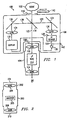
FIGURE 1 illustrates a system for combining multi-spectral images of a scene in accordance with one embodiment of the present invention; -
FIGURE 2 illustrates a viewer ; -
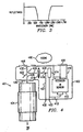
FIGURE 3 illustrates a graph of reflectance vs. wavelength useful for matching a filter to a sensor in connection with the system ofFIGURE 1 ; -
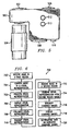
FIGURE 4 illustrates a system for combining multi-spectral images of a scene ; -
FIGURE 5 illustrates a package for housing the system ofFIGURE 4 ; and -
FIGURE 6 is a flowchart demonstrating a method of combining multi-spectral images of a scene in accordance with the present invention. -
FIGURE 1 illustrates a system for combining multi-spectral images of a scene in accordance with one embodiment of the present invention. Asystem 100 for combining multi-spectral images of ascene 102 includes aviewing system 104, such as a pre-existing image intensifier system, and amulti-spectrum image adapter 106.Multi-spectrum image adapter 106 is coupled toviewing system 104 atcoupler 108. For directviewing using adapter 106 without theviewing system 104,viewer 200 shown inFIGURE 2 may be attached or coupled toadapter 106 atcoupler 108. -
Viewing system 104 may be a presently existing intensifier system such as a night vision goggle or monocular. Examples of currently existing night vision equipment suitable for use in connection with the present invention include the following: the AN/PVS-7, the AN/PVS-14 or the AN/PVS-18. Alternatively, a video or still camera could be used in place ofviewing system 104.Viewing system 104 is comprised of anobjective lens 110, animage intensifier tube 112 andviewing optics 114. Whileobjective lens 110 andviewing optics 114 are each depicted as a single lens, it is intended that they may comprise multiple optical elements as is well known to those skilled in the art. Similarly,viewing optics 114 may also comprise multiple optical elements and may be either a monocular or binocular system. - Referring now to
multi-spectral adapter 106, asingle aperture 116 is provided for receiving an image ofscene 102 in multiple spectral ranges or bands. The electromagnetic radiation either generated by or reflected fromscene 102 passes through a broadband transmitting aperture 116 and is split atdichroic mirror 118. As will be subsequently explained,mirror 118 also performs the function of combining images as a beam mixer. At splittingmirror 118 two separateoptical paths path 120 where it is reflected bymirror 124 tolens 126 which focuses the IR radiation onIR sensor 128. Examples of IR sensors useful in practicing the present invention are the Lockheed Martin LIMIRIS IR sensor or the Nytec Boeing IR micro-bolometer sensor U3000. Either of these sensors will generate an analog signal output representative of the IR image ofscene 102. Thevideo output 129 ofIR sensor 128 is transmitted toelectronics 130 for further processing. The electronic output ofvideo output 129 is also available for external transmission throughdata port 142. Conversely, symbology generated externally may be transmitted in throughdata port 142 for presentation at thedisplay 132. In such an embodiment,data port 142 will be bi-directional. In alternative embodiments not shown, more than one data port may be provided to serve multiple functions.Video output 129 is then input to display 132 which converts the IR image signal to a visual representation of the IR image. An example ofdisplay 132 is an active matrix emissive display. That visual representation of the IR image is collimated bylens 134, and folded bymirror 136 which directs the image alongpath 138 todichroic mirror 118 where the image is reflected alongpath 122 to theobjective lens 110 ofviewing system 104. Electromagnetic radiation, such as visible light, is received fromscene 102. The beam passes throughaperture 116 then throughmirror 118 followingpath 122 to theobjective lens 110 ofviewing system 104. In this way an image of the scene in the visible region or primary spectral range is combined with an image of the scene depicting the infrared region or secondary spectral range for observation by a user throughviewing system 104. -
Adapter 106 also includes filter 140 which is operable to coveraperture 116 and is selected to filter out predetermined spectral ranges. For instance, filter 140 may be adapted to block visual and near infrared should it be desired to usesystem 100 in a mode of operation to solely view the IR portion. It is also possible to construct filter 140 so that multiple spectral ranges may be filtered out to enhance certain scenes. -
FIGURE 2 illustrates atelescopic viewer 200 used in connection with the system ofFIGURE 1 .Viewer 200 hasinput adapter 202 for mating withcoupler 108 ofadapter 106. In this way,viewer 200 is substituted forviewing system 104 if the user desires to observe the multi-spectral scene visually without an image intensifier. The image transmitted alongpath 122 entersviewer 200 atinput 204 which conveys the beam throughinverter 205 toobjective lens 206 which then outputs the image toviewing optics 208 which presents the image to a user ateye piece 210.Inverter 205 inverts the image for upright presentation to the user. -
FIGURE 3 illustrates a graph of reflectance vs. wavelength useful for matchingfilter 118 ofFIGURE 1 , to a sensor, such asIR sensor 128, in connection with the embodiment of the present invention depicted inFIGURE 1 . Referring toFIGURE 3 , a selected filter with the reflectance versus wavelength characteristics shown in the graph will only permit radiation of wavelengths between approximately 600 nanometers and 1100 nanometers to pass throughdichroic filter 118. Different spectral characteristics offilter 118 may be selected to conform to other spectral bands of operation. -
FIGURE 4 illustrates a comparative example for a system for combining multi-spectral images of a scene.Adapter module 402 is provided for coupling to aviewer 404 which may be a pre-existing intensifier system such as a night vision goggle. Bycoupling adapter module 402 toviewer 404, the combinedsystem 401 permits the user of the pre-existing intensifier system to observescene 400 in multiple spectral regions.Adapter module 402 hasdual apertures scene 400. Such electromagnetic radiation entersadapter 402 ataperture 406 which is conveyed through IRobjective assembly 410. IR objective assembly collects and focuses the IR radiation ontoIR sensor 412 which converts the IR radiation to an electronic signal. The electronic output ofIR sensor 412 is transmitted alongelectrical conductor 413 to display 414 where the electrical signal is converted to a visual output. The output ofIR sensor 412 may also be externally transmitted viadata port 433. In one embodiment, the output ofIR sensor 412 would be an electronic signal, either analog or digital that may be processed by modifying the image electronically. In another embodiment, the output ofdisplay 414 is transmitted todata port 432 by a spatially coherent fiber optic bundle, or its equivalent, for observation or display to a user either locally or at a remote location. The visual output ofdisplay 414 is projected throughoptical element 418 which collimates the image and transmits the beam alongpath 426 tobeam splitter 422.Beam splitter 422 combines the displayed image with the direct image ofscene 400 in the visible spectrum throughaperture 408. The image in the visible region passes throughbeam splitter 422. The combined image is transmitted tooutput 430 which is connected toviewer 404 where the combined images are available for viewing by a user. Both the IR image and the visible light image may be enhanced or isolated by the choice of suitable filters placed in front ofapertures -
FIGURE 5 illustrates a package for housing the system ofFIGURE 4 .Housing 500 is provided withopening 502 for receiving visible light in a first spectral range.Opening 502 corresponds toaperture 408 ofFIGURE 4 . The visiblelight entering housing 500 throughopening 502 is transmitted to aviewing system 504 such as a pre-existing image intensifier system or night vision device.Housing 500 is also provided withaperture 506 for receiving infrared radiation in a second spectral range.Aperture 506 corresponds toaperture 406 ofFIGURE 4 and is provided to convey the IR radiation to an IR sensor such assensor 412 ofFIGURE 4 . An energy supply, such as a battery, is provided atbattery compartment 508. Adata port 510 is also provided. Electronic control switches 512 and 513, for controlling various functions of the system would be coupled to suitable control electronics (now shown) withinhousing 500. The configuration shown inFIGURE 5 provides for easy adaptation to currently existing night vision equipment such as night vision goggles or monoculars as well as normal visible day scopes of a similar configuration. This comparative example depicted inFIGURES 4 and5 allows for direct viewing of the multi-spectral image by positioning the eye behindaperture 430, without requiring use of a telescopic viewer such asviewer 200 shown inFIGURE 2 . -
FIGURE 6 is a flowchart demonstrating a method of combining multi-spectral images of a scene in accordance with the present invention.Method 700 begins atstep 702 where the multi-spectral adapter receives an image in a secondary spectral band. By way of example, the secondary band might be in the infrared spectrum. Alternatively, other bands such as the UV band may also be detected. Instep 704, the image received in the secondary band is converted to a visual representation of the image. Using the example of an infrared detection system, a hot object will be generally displayed visually as brighter than its surrounding environment. In an alternative embodiment, atstep 705, the visual representation of the image may be processed electronically. Processing the image includes modifying or enhancing the image as is well known to those skilled in the art. The visual representation of the image in the secondary band , or a processed version of that image, is then displayed atstep 706. In one embodiment of the present invention, the image may be displayed externally by routing the signal to a data port for further transmission to other external display devices such as a video monitor, camera or radio transmitter for transmission to remote locations. The displayed visual image is then collimated atstep 708 which would include collimating the image at a collimator. The collimated image is then transmitted instep 710 to a device for combining the visual representation with an image in the primary spectral band. Instep 712, an image is received in the primary spectral band such as the visible spectrum. The visible image is then combined, atstep 714, with the visual representation derived from the image in the secondary band. The combined images are then intensified atstep 716. Typically, an image intensifier system such as a night vision goggle would be suitable for this purpose. Atstep 718, the intensified images are displayed as a combined single image for observation by a user. In an alternative embodiment, atstep 720, other data or information may be superimposed on the displayed multi-spectral image. While the invention has been illustrated as a single device, it should be understood that the various components, such as theIR sensor 128,FIGURE 1 , may be located remotely from the various other components. - Although embodiments of the invention and their advantages are described in detail, a person skilled in the art could make various alternations, additions, and omissions without departing from the scope of the present invention as defined by the appended claims.
Claims (19)
- A system (100) for combining multi-spectral images of a scene (102), the system (100) comprising a multi-spectrum image adapter (106) which comprises a dichroic mirror (11 8) for passing through a scene image in a first spectral band and for reflecting the scene image in a second spectral band, the first spectral band being visible light and the second spectral band being in the infrared region;a channel (122) for transmitting the scene image in the first spectral band;a focusing lens (126) for focusing the scene image in the second spectral band on a detector (128);the detector (128) for sensing the scene image in the second spectral band, the detector having an image output (129) representative of the scene image:a display (132) for receiving the image output and displaying a displayed image in the first spectral band;a collimator (134) for receiving and collimating the displayed image:wherein the dichroic mirror (118) is arranged and configured such as to also combine the transmitted scene image in the first spectral band with the collimated image, and as to convey the combined multi-spectral images to an output and the system (100) further comprisinga viewing system (104) coupled to the output and comprising an image intensifier system (110, 112, 114).
- The system of Claim 1 wherein the display is an active matrix display.
- The system of Claim 1 wherein the representative output of the detector (128) is an analog video signal.
- The system of Claim 1 wherein the representative output of the detector (128) is a digital video signal.
- The system of Claim 1 wherein the viewing system (104) is a night vision device.
- The system of Claim 1 wherein the viewing system is a camera.
- The system of Claim 1 further comprising a data port (142) for transmitting the scene image to a remote source.
- The system of Claim 1 further comprising a data port (142) for receiving information from a remote source or other modular instrument.
- The system of Claim 1 further comprising a data port (142) for receiving information from a remote source and wherein the display is adapted to receive and display data from the remote source.
- The system of Claim 1 wherein the first and second spectral bands share a common aperture (116).
- The system of any of the preceding claims wherein said system is configured and adapted such that electromagnetic radiation of one or more spectral bands passes through only one dichroic mirror (118) between said scene and said output of the system.
- The system of claim 11 wherein said one or more spectral bands comprise said first spectral band.
- A method for combining multi-spectral images of a scene (102), the method comprising:passing through a dichroic mirror (118) a scene image in a first spectral band and reflecting the scene image in a second spectral band at the dichroic mirror (118), the first spectral band being visible light and the second spectral band being in the infrared region;focusing the scene image in the second spectral band onto an infrared detector (128) of a multi-spectrum image adapter (106);receiving an infrared (IR) image of the scene at the infrared detector (128; ;generating a representation (129; 143) of the IR image in the multi-spectrum image adapter (106);transmitting the IR image representation to a display (132) of the multi-spectrum image-adapter(106);generating a visual representation of the IR image as a displayed IR image at the display:collimating the displayed IR image in the multi-spectrum image adapter (106 );combining the collimated IR image with the scene image in the first spectral band by means of the dichroic mirror (118) in the multi-spectrum image adapter (106);transmitting the combined images to an intensifier system (104) operable to intensify images in the first spectral band and being coupled to the multi-spectum image adapter (106); anddisplaying the combined images of the scene in the intensifier system (104 ) as a combined single image.
- The method of Claim 13 wherein the intensifier system (104) is a night vision goggle.
- The method of Claim 13 wherein the visual representation of the IR image is displayed at an external viewer (104).
- The method of Claim 13 further comprising transmitting the visual representation of the image to a data port (142).
- The method of Claim 13 further comprising superimposing data on the combined multi-spectral images of the scene.
- The method of Claim 13 further comprising processing the IR image representation.
- The method of any of Claims 13 to 18 wherein electromagnetic radiation of one or more spectral bands passes through only one dichroic mirror (118) between said scene and said transmitting of the combined images.
Applications Claiming Priority (3)
| Application Number | Priority Date | Filing Date | Title |
|---|---|---|---|
| US09/528,552 US7053928B1 (en) | 2000-03-20 | 2000-03-20 | Method and system for combining multi-spectral images of a scene |
| US528552 | 2000-03-20 | ||
| PCT/US2001/005258 WO2001072033A1 (en) | 2000-03-20 | 2001-02-20 | Method and system for combining multi-spectral images |
Publications (4)
| Publication Number | Publication Date |
|---|---|
| EP1269745A1 EP1269745A1 (en) | 2003-01-02 |
| EP1269745A4 EP1269745A4 (en) | 2004-09-01 |
| EP1269745B1 EP1269745B1 (en) | 2007-10-17 |
| EP1269745B2 true EP1269745B2 (en) | 2013-04-17 |
Family
ID=24106152
Family Applications (1)
| Application Number | Title | Priority Date | Filing Date |
|---|---|---|---|
| EP01920117.7A Expired - Lifetime EP1269745B2 (en) | 2000-03-20 | 2001-02-20 | Method and system for combining multi-spectral images |
Country Status (4)
| Country | Link |
|---|---|
| US (1) | US7053928B1 (en) |
| EP (1) | EP1269745B2 (en) |
| IL (2) | IL151085A0 (en) |
| WO (1) | WO2001072033A1 (en) |
Families Citing this family (31)
| Publication number | Priority date | Publication date | Assignee | Title |
|---|---|---|---|---|
| WO2003107088A2 (en) | 2002-06-01 | 2003-12-24 | Litton Systems, Inc. | Image intensification camera |
| US7092013B2 (en) | 2002-06-12 | 2006-08-15 | Litton Systems, Inc. | InGaAs image intensifier camera |
| WO2003104877A1 (en) | 2002-06-05 | 2003-12-18 | Litton Systems, Inc. | Enhanced night vision goggle assembly |
| AU2003238852A1 (en) * | 2002-06-06 | 2003-12-22 | Litton Systems, Inc. | Integrated display image intensifier assembly |
| US7274830B2 (en) | 2002-06-12 | 2007-09-25 | Litton Systems, Inc. | System for multi-sensor image fusion |
| US6970190B2 (en) | 2002-06-12 | 2005-11-29 | Litton Systems, Inc. | Event synchronization for detector systems |
| JP2004304718A (en) * | 2003-04-01 | 2004-10-28 | Nara Institute Of Science & Technology | Apparatus and method for extracting image of close region |
| US7091930B2 (en) * | 2003-08-02 | 2006-08-15 | Litton Systems, Inc. | Centerline mounted sensor fusion device |
| US7307793B2 (en) | 2004-07-02 | 2007-12-11 | Insight Technology, Inc. | Fusion night vision system |
| US8585584B2 (en) * | 2004-10-11 | 2013-11-19 | Nitesh Ratnakar | Dual view endoscope |
| US7459684B2 (en) * | 2005-05-18 | 2008-12-02 | Lockheed Martin Corporation | Long-wavelength infra-red night vision goggles |
| US7211778B1 (en) * | 2005-10-07 | 2007-05-01 | Itt Manufacturing Enterprises, Inc. | Night vision goggle with separate camera and user output paths |
| US7483213B2 (en) * | 2006-03-24 | 2009-01-27 | Omnitech Partners | Image combining viewer |
| EP2104340A1 (en) * | 2008-03-19 | 2009-09-23 | Barco N.V. | Combined thermal and visible imaging |
| US20090278929A1 (en) * | 2008-05-06 | 2009-11-12 | Flir Systems Inc | Video camera with interchangable optical sensors |
| US20110141223A1 (en) * | 2008-06-13 | 2011-06-16 | Raytheon Company | Multiple Operating Mode Optical Instrument |
| US9077916B2 (en) | 2009-01-16 | 2015-07-07 | Dual Aperture International Co. Ltd. | Improving the depth of field in an imaging system |
| EP2471258B1 (en) * | 2009-08-25 | 2017-05-24 | Dual Aperture International Co. Ltd. | Reducing noise in a color image |
| US8102306B2 (en) | 2010-05-13 | 2012-01-24 | The United States Of America As Represented By The Secretary Of The Navy | Active-radar-assisted passive composite imagery for aiding navigation or detecting threats |
| WO2012052352A1 (en) * | 2010-10-19 | 2012-04-26 | Bae Systems Plc | Viewing device comprising an image combiner |
| US8379123B2 (en) | 2010-12-13 | 2013-02-19 | Research In Motion Limited | System and method of capturing low-light images on a mobile device |
| US9638846B2 (en) | 2011-07-20 | 2017-05-02 | Power Diagnostic Technologies Ltd. | Apparatus and method for multi-spectral dual balanced imaging |
| US8638387B2 (en) * | 2012-01-25 | 2014-01-28 | Optex Systems, Inc. | Multiple spectral single image sighting system using single objective lens set |
| DE102013020598B4 (en) * | 2013-12-13 | 2017-09-14 | Steiner-Optik Gmbh | Magnifying optical device |
| US10057509B2 (en) | 2014-05-30 | 2018-08-21 | Flir Systems, Inc. | Multiple-sensor imaging system |
| US9977961B2 (en) * | 2014-10-21 | 2018-05-22 | Bae Systems Information And Electronic Systems Integration Inc. | Method for maintaining detection capability when a frame in a multispectral image is corrupted |
| US20160255323A1 (en) | 2015-02-26 | 2016-09-01 | Dual Aperture International Co. Ltd. | Multi-Aperture Depth Map Using Blur Kernels and Down-Sampling |
| US10359618B2 (en) | 2016-01-11 | 2019-07-23 | Nikon Corporation | Multispectral stereoscopic endoscope system and use of same |
| US11054629B1 (en) * | 2020-01-17 | 2021-07-06 | L3Harris Technologies, Inc. | Nightvision with integrated micro-display module |
| US20230333362A1 (en) | 2021-03-26 | 2023-10-19 | Uab "Yukon Advanced Optics Worldwide" | Apparatus And Method For Combined Use Of Two Independent Monoculars |
| FR3137765A1 (en) * | 2022-07-08 | 2024-01-12 | Safran Electronics & Defense | Compact observation device configured to superimpose an image of an observed scene and a processed image of the observed scene. |
Citations (13)
| Publication number | Priority date | Publication date | Assignee | Title |
|---|---|---|---|---|
| US3748471A (en) † | 1971-09-24 | 1973-07-24 | Int Imaging Syst | False color radiant energy detection method and apparatus |
| GB1328128A (en) † | 1969-12-11 | 1973-08-30 | Hughes Aircraft Co | Optical mechanical raster scanning apparatus |
| US3997762A (en) † | 1974-10-09 | 1976-12-14 | David Scarth Ritchie | Fire control system |
| US4672439A (en) † | 1985-09-04 | 1987-06-09 | Texas Instruments Incorporated | FLIR imager with hybrid optical/electronic processor |
| US4786966A (en) † | 1986-07-10 | 1988-11-22 | Varo, Inc. | Head mounted video display and remote camera system |
| US4818065A (en) † | 1987-03-04 | 1989-04-04 | Elbit Computers Ltd. | Optical device particularly useful as as night vision goggles |
| US4902128A (en) † | 1983-08-16 | 1990-02-20 | Hughes Aircraft Company | Apparatus for harmonizing a plurality of optical/optronic axis of sighting apparatus to a common axis |
| US5035472A (en) † | 1990-06-20 | 1991-07-30 | The United States Of America As Represented By The Secretary Of The Army | Integrated multispectral man portable weapon sight |
| US5084780A (en) † | 1989-09-12 | 1992-01-28 | Itt Corporation | Telescopic sight for day/night viewing |
| US5204774A (en) † | 1991-12-06 | 1993-04-20 | Varo Inc. | Night vision goggle with improved optical system |
| US5282082A (en) † | 1990-07-31 | 1994-01-25 | Thomson Trt Defense | Day-and-night optical observation device |
| US5497266A (en) † | 1994-07-27 | 1996-03-05 | Litton Systems, Inc. | Telescopic day and night sight |
| US5903996A (en) † | 1997-08-01 | 1999-05-18 | Morley; Roland M. | Day/night viewing device with laser range finder utilizing two wavelengths of laser light, and method of its operation |
Family Cites Families (11)
| Publication number | Priority date | Publication date | Assignee | Title |
|---|---|---|---|---|
| US4463252A (en) | 1982-01-04 | 1984-07-31 | Baird Corporation | Night vision goggle system |
| US4602861A (en) | 1982-12-23 | 1986-07-29 | Minolta Camera Kabushiki Kaisha | Auto-focusing system |
| US4708475A (en) * | 1983-06-30 | 1987-11-24 | Atlantic Richfield Company | Portable luminescence sensor |
| GB2163548B (en) * | 1984-08-09 | 1987-11-25 | Perkin Elmer Ltd | Interferometric apparatus particularly for use in ft spectrophotometer |
| US4751571A (en) | 1987-07-29 | 1988-06-14 | General Electric Company | Composite visible/thermal-infrared imaging apparatus |
| US5264961A (en) | 1989-10-10 | 1993-11-23 | Unisys Corporation | Techniques for trapping beams of infra-red energy |
| JPH0777665A (en) * | 1993-03-29 | 1995-03-20 | Canon Inc | Image display device and image photographing device for the same |
| US5910816A (en) | 1995-06-07 | 1999-06-08 | Stryker Corporation | Imaging system with independent processing of visible an infrared light energy |
| US5729010A (en) | 1996-09-11 | 1998-03-17 | The United States Of America As Represented By The Secretary Of The Air Force | Night vision device localized irradiance attenuation |
| JP4304752B2 (en) * | 1999-02-24 | 2009-07-29 | ソニー株式会社 | Hologram recording / reproducing method and hologram recording / reproducing apparatus |
| US6088165A (en) * | 1999-04-28 | 2000-07-11 | Itt Manufacturing Enterprises | Enhanced night vision device |
-
2000
- 2000-03-20 US US09/528,552 patent/US7053928B1/en not_active Expired - Lifetime
-
2001
- 2001-02-20 IL IL15108501A patent/IL151085A0/en unknown
- 2001-02-20 WO PCT/US2001/005258 patent/WO2001072033A1/en active IP Right Grant
- 2001-02-20 EP EP01920117.7A patent/EP1269745B2/en not_active Expired - Lifetime
-
2002
- 2002-08-05 IL IL151085A patent/IL151085A/en active IP Right Review Request
Patent Citations (13)
| Publication number | Priority date | Publication date | Assignee | Title |
|---|---|---|---|---|
| GB1328128A (en) † | 1969-12-11 | 1973-08-30 | Hughes Aircraft Co | Optical mechanical raster scanning apparatus |
| US3748471A (en) † | 1971-09-24 | 1973-07-24 | Int Imaging Syst | False color radiant energy detection method and apparatus |
| US3997762A (en) † | 1974-10-09 | 1976-12-14 | David Scarth Ritchie | Fire control system |
| US4902128A (en) † | 1983-08-16 | 1990-02-20 | Hughes Aircraft Company | Apparatus for harmonizing a plurality of optical/optronic axis of sighting apparatus to a common axis |
| US4672439A (en) † | 1985-09-04 | 1987-06-09 | Texas Instruments Incorporated | FLIR imager with hybrid optical/electronic processor |
| US4786966A (en) † | 1986-07-10 | 1988-11-22 | Varo, Inc. | Head mounted video display and remote camera system |
| US4818065A (en) † | 1987-03-04 | 1989-04-04 | Elbit Computers Ltd. | Optical device particularly useful as as night vision goggles |
| US5084780A (en) † | 1989-09-12 | 1992-01-28 | Itt Corporation | Telescopic sight for day/night viewing |
| US5035472A (en) † | 1990-06-20 | 1991-07-30 | The United States Of America As Represented By The Secretary Of The Army | Integrated multispectral man portable weapon sight |
| US5282082A (en) † | 1990-07-31 | 1994-01-25 | Thomson Trt Defense | Day-and-night optical observation device |
| US5204774A (en) † | 1991-12-06 | 1993-04-20 | Varo Inc. | Night vision goggle with improved optical system |
| US5497266A (en) † | 1994-07-27 | 1996-03-05 | Litton Systems, Inc. | Telescopic day and night sight |
| US5903996A (en) † | 1997-08-01 | 1999-05-18 | Morley; Roland M. | Day/night viewing device with laser range finder utilizing two wavelengths of laser light, and method of its operation |
Non-Patent Citations (3)
| Title |
|---|
| A.A. CAMERON: "Integrated Night Vision in Helmet-mounted Displays 1999", GEC REV., vol. 14, no. 1 † |
| A.M. WAXMAN, ET AL.,: "Solid-State Colour Night Vision: Fusion of Low-Light Visible and Thermal Infrared Imagery", LICOLN LABOURATORY JOURNAL, vol. 11, no. 1,2998 † |
| G.GIVENS, Z. YONA: "Helmet mounted display (day/night) assumed publication 1996" † |
Also Published As
| Publication number | Publication date |
|---|---|
| IL151085A (en) | 2008-03-20 |
| EP1269745B1 (en) | 2007-10-17 |
| EP1269745A4 (en) | 2004-09-01 |
| EP1269745A1 (en) | 2003-01-02 |
| US7053928B1 (en) | 2006-05-30 |
| WO2001072033A1 (en) | 2001-09-27 |
| IL151085A0 (en) | 2003-04-10 |
Similar Documents
| Publication | Publication Date | Title |
|---|---|---|
| EP1269745B2 (en) | Method and system for combining multi-spectral images | |
| EP1549993B1 (en) | Enhanced night vision goggle assembly | |
| US7911687B2 (en) | Sighted device operable in visible-wavelength or electro-optical/visible-wavelength sighting modes | |
| US7110184B1 (en) | Method and apparatus for combining an induced image with a scene image | |
| US6570147B2 (en) | Color night vision apparatus | |
| US7755047B2 (en) | Clip-on infrared imager | |
| US6798578B1 (en) | Integrated display image intensifier assembly | |
| US7170057B2 (en) | Image enhancement system and method for night goggles | |
| US7813037B2 (en) | Day/night-vision device | |
| US7746551B2 (en) | Vision system with eye dominance forced to fusion channel | |
| EP3401631B1 (en) | Thermal reflex sight | |
| EP0206324A2 (en) | Dual source display apparatus | |
| US8860831B1 (en) | Brightness tracking light sensor | |
| JP5953636B2 (en) | Modular night vision system with fusion optical sensor | |
| US20030231245A1 (en) | Ingaas image intensifier camera | |
| US9426389B1 (en) | Second imaging device adaptable for use with first imaging device and method for using same | |
| US20230333362A1 (en) | Apparatus And Method For Combined Use Of Two Independent Monoculars | |
| US11867908B2 (en) | Folded optic augmented reality display | |
| AU2003238854B2 (en) | Enhanced night vision goggle assembly | |
| GB2247088A (en) | Imaging apparatus |
Legal Events
| Date | Code | Title | Description |
|---|---|---|---|
| PUAI | Public reference made under article 153(3) epc to a published international application that has entered the european phase |
Free format text: ORIGINAL CODE: 0009012 |
|
| 17P | Request for examination filed |
Effective date: 20020802 |
|
| AK | Designated contracting states |
Kind code of ref document: A1 Designated state(s): AT BE CH CY DE DK ES FI FR GB GR IE IT LI LU MC NL PT SE TR |
|
| AX | Request for extension of the european patent |
Free format text: AL;LT;LV;MK;RO;SI |
|
| RBV | Designated contracting states (corrected) |
Designated state(s): AT BE CH GB LI |
|
| REG | Reference to a national code |
Ref country code: DE Ref legal event code: 8566 |
|
| A4 | Supplementary search report drawn up and despatched |
Effective date: 20040720 |
|
| RIC1 | Information provided on ipc code assigned before grant |
Ipc: 7G 02F 1/01 B Ipc: 7G 02B 7/18 B Ipc: 7H 04N 5/222 A |
|
| 17Q | First examination report despatched |
Effective date: 20041129 |
|
| 17Q | First examination report despatched |
Effective date: 20041129 |
|
| GRAP | Despatch of communication of intention to grant a patent |
Free format text: ORIGINAL CODE: EPIDOSNIGR1 |
|
| GRAS | Grant fee paid |
Free format text: ORIGINAL CODE: EPIDOSNIGR3 |
|
| GRAA | (expected) grant |
Free format text: ORIGINAL CODE: 0009210 |
|
| RBV | Designated contracting states (corrected) |
Designated state(s): CH GB LI |
|
| AK | Designated contracting states |
Kind code of ref document: B1 Designated state(s): CH GB LI |
|
| REG | Reference to a national code |
Ref country code: GB Ref legal event code: FG4D |
|
| REG | Reference to a national code |
Ref country code: CH Ref legal event code: EP |
|
| REG | Reference to a national code |
Ref country code: CH Ref legal event code: NV Representative=s name: RENTSCH & PARTNER |
|
| PLBI | Opposition filed |
Free format text: ORIGINAL CODE: 0009260 |
|
| PLAX | Notice of opposition and request to file observation + time limit sent |
Free format text: ORIGINAL CODE: EPIDOSNOBS2 |
|
| 26 | Opposition filed |
Opponent name: ELBIT SYSTEMS LTD. Effective date: 20080716 |
|
| PLAB | Opposition data, opponent's data or that of the opponent's representative modified |
Free format text: ORIGINAL CODE: 0009299OPPO |
|
| PLAF | Information modified related to communication of a notice of opposition and request to file observations + time limit |
Free format text: ORIGINAL CODE: EPIDOSCOBS2 |
|
| PLBB | Reply of patent proprietor to notice(s) of opposition received |
Free format text: ORIGINAL CODE: EPIDOSNOBS3 |
|
| REG | Reference to a national code |
Ref country code: CH Ref legal event code: PFA Owner name: NORTHROP GRUMMAN GUIDANCE AND ELECTRONICS COMPANY Free format text: LITTON SYSTEMS, INC.#21240 BURBANK BOULEVARD#WOODLAND HILLS, CALIFORNIA 91367 (US) -TRANSFER TO- NORTHROP GRUMMAN GUIDANCE AND ELECTRONICS COMPANY, INC.#1840 CENTURY PARK EAST#LOS ANGELES, CA 90067 (US) Ref country code: CH Ref legal event code: NV Representative=s name: KATZAROV S.A. Ref country code: CH Ref legal event code: PUE Owner name: L-3 COMMUNICATIONS CORPORATION Free format text: NORTHROP GRUMMAN GUIDANCE AND ELECTRONICS COMPANY, INC.#1840 CENTURY PARK EAST#LOS ANGELES, CA 90067 (US) -TRANSFER TO- L-3 COMMUNICATIONS CORPORATION#600 THIRD AVENUE, 34TH FLOOR#NEW YORK, NY 10016 (US) |
|
| RAP2 | Party data changed (patent owner data changed or rights of a patent transferred) |
Owner name: L-3 COMMUNICATIONS CORPORATION |
|
| REG | Reference to a national code |
Ref country code: CH Ref legal event code: NV Representative=s name: RENTSCH & PARTNER |
|
| REG | Reference to a national code |
Ref country code: GB Ref legal event code: 732E Free format text: REGISTERED BETWEEN 20110414 AND 20110420 |
|
| REG | Reference to a national code |
Ref country code: CH Ref legal event code: PFA Owner name: L-3 COMMUNICATIONS CORPORATION Free format text: L-3 COMMUNICATIONS CORPORATION#600 THIRD AVENUE, 34TH FLOOR#NEW YORK, NY 10016 (US) -TRANSFER TO- L-3 COMMUNICATIONS CORPORATION#600 THIRD AVENUE, 34TH FLOOR#NEW YORK, NY 10016 (US) |
|
| PUAH | Patent maintained in amended form |
Free format text: ORIGINAL CODE: 0009272 |
|
| STAA | Information on the status of an ep patent application or granted ep patent |
Free format text: STATUS: PATENT MAINTAINED AS AMENDED |
|
| 27A | Patent maintained in amended form |
Effective date: 20130417 |
|
| AK | Designated contracting states |
Kind code of ref document: B2 Designated state(s): CH GB LI |
|
| PGFP | Annual fee paid to national office [announced via postgrant information from national office to epo] |
Ref country code: CH Payment date: 20130220 Year of fee payment: 13 |
|
| REG | Reference to a national code |
Ref country code: CH Ref legal event code: AELC |
|
| REG | Reference to a national code |
Ref country code: CH Ref legal event code: PL |
|
| PG25 | Lapsed in a contracting state [announced via postgrant information from national office to epo] |
Ref country code: LI Free format text: LAPSE BECAUSE OF NON-PAYMENT OF DUE FEES Effective date: 20140228 Ref country code: CH Free format text: LAPSE BECAUSE OF NON-PAYMENT OF DUE FEES Effective date: 20140228 |
|
| PGFP | Annual fee paid to national office [announced via postgrant information from national office to epo] |
Ref country code: GB Payment date: 20200219 Year of fee payment: 20 |
|
| REG | Reference to a national code |
Ref country code: GB Ref legal event code: PE20 Expiry date: 20210219 |
|
| PG25 | Lapsed in a contracting state [announced via postgrant information from national office to epo] |
Ref country code: GB Free format text: LAPSE BECAUSE OF EXPIRATION OF PROTECTION Effective date: 20210219 |