EP1271094A1 - Bore depth measuring device for a driller - Google Patents
Bore depth measuring device for a driller Download PDFInfo
- Publication number
- EP1271094A1 EP1271094A1 EP02008353A EP02008353A EP1271094A1 EP 1271094 A1 EP1271094 A1 EP 1271094A1 EP 02008353 A EP02008353 A EP 02008353A EP 02008353 A EP02008353 A EP 02008353A EP 1271094 A1 EP1271094 A1 EP 1271094A1
- Authority
- EP
- European Patent Office
- Prior art keywords
- drilling
- distance
- depth
- distance meter
- drilling depth
- Prior art date
- Legal status (The legal status is an assumption and is not a legal conclusion. Google has not performed a legal analysis and makes no representation as to the accuracy of the status listed.)
- Withdrawn
Links
Images

Classifications
-
- B—PERFORMING OPERATIONS; TRANSPORTING
- B23—MACHINE TOOLS; METAL-WORKING NOT OTHERWISE PROVIDED FOR
- B23B—TURNING; BORING
- B23B49/00—Measuring or gauging equipment on boring machines for positioning or guiding the drill; Devices for indicating failure of drills during boring; Centering devices for holes to be bored
- B23B49/003—Stops attached to drilling tools, tool holders or drilling machines
- B23B49/006—Attached to drilling machines
- B23B49/008—Attached to the nose of the drilling machines
-
- B—PERFORMING OPERATIONS; TRANSPORTING
- B23—MACHINE TOOLS; METAL-WORKING NOT OTHERWISE PROVIDED FOR
- B23Q—DETAILS, COMPONENTS, OR ACCESSORIES FOR MACHINE TOOLS, e.g. ARRANGEMENTS FOR COPYING OR CONTROLLING; MACHINE TOOLS IN GENERAL CHARACTERISED BY THE CONSTRUCTION OF PARTICULAR DETAILS OR COMPONENTS; COMBINATIONS OR ASSOCIATIONS OF METAL-WORKING MACHINES, NOT DIRECTED TO A PARTICULAR RESULT
- B23Q17/00—Arrangements for observing, indicating or measuring on machine tools
- B23Q17/20—Arrangements for observing, indicating or measuring on machine tools for indicating or measuring workpiece characteristics, e.g. contour, dimension, hardness
-
- B—PERFORMING OPERATIONS; TRANSPORTING
- B25—HAND TOOLS; PORTABLE POWER-DRIVEN TOOLS; MANIPULATORS
- B25F—COMBINATION OR MULTI-PURPOSE TOOLS NOT OTHERWISE PROVIDED FOR; DETAILS OR COMPONENTS OF PORTABLE POWER-DRIVEN TOOLS NOT PARTICULARLY RELATED TO THE OPERATIONS PERFORMED AND NOT OTHERWISE PROVIDED FOR
- B25F5/00—Details or components of portable power-driven tools not particularly related to the operations performed and not otherwise provided for
- B25F5/003—Stops for limiting depth in rotary hand tools
-
- B—PERFORMING OPERATIONS; TRANSPORTING
- B25—HAND TOOLS; PORTABLE POWER-DRIVEN TOOLS; MANIPULATORS
- B25H—WORKSHOP EQUIPMENT, e.g. FOR MARKING-OUT WORK; STORAGE MEANS FOR WORKSHOPS
- B25H1/00—Work benches; Portable stands or supports for positioning portable tools or work to be operated on thereby
- B25H1/0021—Stands, supports or guiding devices for positioning portable tools or for securing them to the work
- B25H1/0078—Guiding devices for hand tools
- B25H1/0092—Guiding devices for hand tools by optical means
-
- G—PHYSICS
- G01—MEASURING; TESTING
- G01B—MEASURING LENGTH, THICKNESS OR SIMILAR LINEAR DIMENSIONS; MEASURING ANGLES; MEASURING AREAS; MEASURING IRREGULARITIES OF SURFACES OR CONTOURS
- G01B11/00—Measuring arrangements characterised by the use of optical techniques
- G01B11/02—Measuring arrangements characterised by the use of optical techniques for measuring length, width or thickness
- G01B11/026—Measuring arrangements characterised by the use of optical techniques for measuring length, width or thickness by measuring distance between sensor and object
-
- G—PHYSICS
- G01—MEASURING; TESTING
- G01B—MEASURING LENGTH, THICKNESS OR SIMILAR LINEAR DIMENSIONS; MEASURING ANGLES; MEASURING AREAS; MEASURING IRREGULARITIES OF SURFACES OR CONTOURS
- G01B11/00—Measuring arrangements characterised by the use of optical techniques
- G01B11/22—Measuring arrangements characterised by the use of optical techniques for measuring depth
-
- G—PHYSICS
- G01—MEASURING; TESTING
- G01B—MEASURING LENGTH, THICKNESS OR SIMILAR LINEAR DIMENSIONS; MEASURING ANGLES; MEASURING AREAS; MEASURING IRREGULARITIES OF SURFACES OR CONTOURS
- G01B7/00—Measuring arrangements characterised by the use of electric or magnetic techniques
- G01B7/02—Measuring arrangements characterised by the use of electric or magnetic techniques for measuring length, width or thickness
- G01B7/023—Measuring arrangements characterised by the use of electric or magnetic techniques for measuring length, width or thickness for measuring distance between sensor and object
Definitions
- the invention relates to a device for measuring the depth of a bore, that of a drill, in particular a hand-held drill, is produced.
- the invention is therefore based on the object of a device for measurement the depth of a hole created by a drill to create the easy determination of the drilling depth and even with handheld drilling rigs a simple compliance with a predetermined value of such a drilling depth is permitted.
- such a device is characterized according to the invention through one, at a bearing section near the rotating one Drill head of the drill arranged, non-contact distance meter Determination of the distance from the changing with the drilling depth Workpiece.
- the distance meter, the one on optical, acoustic, capacitive or inductive Basis working sensors can preferably determine the drilling depth each as the difference between the current distance and the initial distance at Position the drill on the workpiece.
- the workpiece is understood in the According to the invention, each component in which a borehole has a predetermined To be drilled deep, for example also a wall or a ceiling.
- the distance meter can have a preferably or battery-operated, electronics that have a display device is assigned for the respective drilling depth, preferably an input device, in particular an input keyboard for specifying a desired drilling depth should be present.
- This input keyboard enables in connection with a memory device of the electronics the activation of an optical or acoustic signal device for displaying a predetermined drilling depth or, if necessary also switching off the drill so that the specified one Drilling depth is not exceeded, not even accidentally.
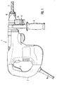
- a spacer according to the invention as a separate component in its own housing 7 8 is fastened in a manner not shown in more detail, which with an optical, acoustic, capacitive or inductive based sensors is.
- the distance meter 8 has an input keyboard in the exemplary embodiment shown 9 and an input button 10, with the aid of which a reset is carried out when attaching the drilling tool again to a wall or a Workpiece can take place, so that the measurement of the drilling depth Difference determination of the initial distance at zeroing the distance meter from the wall or the workpiece and the current one Wall distance can be determined. This difference can be found as the drilling depth the display device 11 are displayed, with an additional one optical or acoustic display device 12 may be present when reaching flashes or triggers a tone so that the Operator immediately recognize when the specified drilling depth is reached can. If necessary, the drive can also be switched off at this time for the drill head 13 of the drill.
- the structure of the sensors can, depending on whether they are optical, acoustic, capacitive or inductive base works, be designed differently, so it is not shown in detail in the drawings.
- Such non-contact Sensor systems for a distance measurement are known per se.
- the Exit for example, of a laser beam generated by a laser diode for a
- the optical distance measurement lies in the front wall 15 remote from the wall 14 of the housing 7 of the distance meter 8.
- the housing 7 can in addition to the Sensor technology and electronics also a battery or rechargeable battery for supply of the distance meter. If the distance meter is permanently installed on a drilling machine, preferably with integration in its housing, it is generally more convenient to use electrical power Power supply to the drilling device 1 via its connecting cable 16.
Abstract
Description
Die Erfindung bezieht sich auf eine Vorrichtung zur Messung der Tiefe einer Bohrung, die von einem Bohrgerät, insbesondere einem handgeführten Bohrgerät, erzeugt wird.The invention relates to a device for measuring the depth of a bore, that of a drill, in particular a hand-held drill, is produced.
Bei ortsfesten Ständerbohrmaschinen ergibt sich die Möglichkeit, die Bohrtiefe durch den jeweiligen Spindelvorschub zu messen, ein Verfahren das bei handgeführten Bohrgeräten grundsätzlich nicht anwendbar ist.With stationary pillar drills there is the possibility of drilling depth to measure by the respective spindle feed, a method that with hand-guided Drilling equipment is generally not applicable.
Für handgeführte Bohrgeräte ist es zwar bereits bekannt, mechanische Abstandhalter zwischen Werkzeug und Werkstück vorzusehen, die verhindern, dass das Werkzeug tiefer in das Werkstück eindringt, als es vorher mit dem Abstandhalter eingestellt wurde. Solche Abstandhalter müssen aber vor dem Bohren durch eine Maßverkörperung auf die Länge des jeweiligen Werkzeugs eingestellt werden, damit die vorgesehene Bohrungstiefe eingehalten werden kann. Dies bedeutet bei jedem Werkzeugwechsel ein umständliches Messen der Werkzeuglänge und ein ebenso umständliches Einstellen des Abstandhalters. In der Praxis hat sich gerade bei handgeführten Bohrgeräten gezeigt, das dieses Einrichten nicht einfach zu bewerkstelligen ist. Es muss das Bohrgerät und eine Maßverkörperung gehalten werden, die Feststellvorrichtung des Abstandhalters gelöst und wieder festgestellt werden und schließlich der Abstandhalter selbst auf die gewünschte Tiefe eingestellt werden. Diese Tätigkeiten müssen alle mehr oder weniger gleichzeitig ausgeführt werden.For hand-held drilling devices, mechanical spacers are already known between the tool and the workpiece to prevent that Tool penetrates deeper into the workpiece than it did with the spacer was discontinued. Such spacers must be drilled through a Material measure can be adjusted to the length of the respective tool, so that the intended drilling depth can be maintained. This means at every time a tool is changed, a laborious measurement of the tool length and a just as complicated adjustment of the spacer. In practice it just has With hand-held drilling rigs, this is not easy to set up is accomplished. The drill and a material measure must be held are released, the locking device of the spacer and fixed again and finally the spacer itself is set to the desired depth become. These activities must all be performed more or less simultaneously become.
Der Erfindung liegt daher die Aufgabe zugrunde, eine Vorrichtung zur Messung der Tiefe einer Bohrung, die von einem Bohrgerät erzeugt wird, zu schaffen, die auch bei handgeführten Bohrgeräten eine einfache Bestimmung der Bohrtiefe und ein einfaches Einhalten eines vorgegebenen Wertes einer solchen Bohrtiefe gestattet.The invention is therefore based on the object of a device for measurement the depth of a hole created by a drill to create the easy determination of the drilling depth and even with handheld drilling rigs a simple compliance with a predetermined value of such a drilling depth is permitted.
Zur Lösung dieser Aufgabe ist eine derartige Vorrichtung erfindungsgemäß gekennzeichnet durch einen, an einem Lagerabschnitt in der Nähe des rotierenden Bohrkopfes des Bohrgerätes angeordneten, berührungslosen Abstandmesser zur Bestimmung des sich mit der Bohrtiefe entsprechend ändernden Abstandes vom Werkstück.To achieve this object, such a device is characterized according to the invention through one, at a bearing section near the rotating one Drill head of the drill arranged, non-contact distance meter Determination of the distance from the changing with the drilling depth Workpiece.
Der Abstandmesser, der eine auf optischer, akustischer, kapazitiver oder induktiver Basis arbeitende Sensorik aufweisen kann, bestimmt die Bohrtiefe bevorzugt jeweils als Differenz des aktuellen Abstandes und des Anfangsabstandes beim Ansetzen des Bohrgerätes am Werkstück. Unter Werkstück versteht man dabei im Sinne der Erfindung jedes Bauteil, in welches ein Bohrloch einer vorgegebenen Tiefe gebohrt werden soll, also beispielsweise auch eine Wand oder eine Decke.The distance meter, the one on optical, acoustic, capacitive or inductive Basis working sensors can preferably determine the drilling depth each as the difference between the current distance and the initial distance at Position the drill on the workpiece. The workpiece is understood in the According to the invention, each component in which a borehole has a predetermined To be drilled deep, for example also a wall or a ceiling.
Der Abstandmesser kann in Ausgestaltung der Erfindung eine, vorzugsweise Akku- oder Batterie- betriebene, Elektronik aufweisen, der eine Anzeigevorrichtung für die jeweilige Bohrtiefe zugeordnet ist, wobei bevorzugt eine Eingabevorrichtung, insbesondere eine Eingabetastatur zur Vorgabe einer gewünschten Bohrtiefe vorhanden sein sollte. Diese Eingabetastatur ermöglicht in Verbindung mit einer Speichereinrichtung der Elektronik die Aktivierung einer optischen oder akustischen Signaleinrichtung zur Anzeige einer vorgegebenen Bohrtiefe oder gegebenenfalls auch eines Ausschaltens des Bohrgeräts, damit die vorgegebene Bohrtiefe nicht, auch nicht versehentlich, überschritten wird.In an embodiment of the invention, the distance meter can have a preferably or battery-operated, electronics that have a display device is assigned for the respective drilling depth, preferably an input device, in particular an input keyboard for specifying a desired drilling depth should be present. This input keyboard enables in connection with a memory device of the electronics the activation of an optical or acoustic signal device for displaying a predetermined drilling depth or, if necessary also switching off the drill so that the specified one Drilling depth is not exceeded, not even accidentally.
Neben der Möglichkeit einen erfindungsgemäßen Abstandmesser direkt in das Gehäuse des Bohrgerätes zu integrieren, hat es sich in der Praxis als besonders zweckmäßig erwiesen, wenn der Abstandmesser als selbstständiges Bauteil, vorzugsweise lösbar, am Bohrgerät befestigbar ist. Dies ermöglicht nicht nur das beliebige Nachrüsten vorhandener Bohrgeräte, sondern auch den Austausch des Abstandmessers von einem Bohrgerät zum anderen, wobei es auf die positionsgenaue Anordnung an einer bestimmten Stelle des jeweiligen Bohrgerätes gar nicht ankommt, da ja die Bohrtiefe über die Differenz des aktuellen Abstandes und des Anfangsabstandes des Abstandmessers vom Werkstück bestimmt wird. In addition to the possibility of a distance meter according to the invention directly in the Integrating the housing of the drilling rig has proven to be special in practice Proven useful if the spacer as a separate component, preferably detachable, can be attached to the drill. This not only enables anything Retrofitting existing drilling rigs, but also replacing the Distance meter from one drill to another, taking it to the exact position Arrangement at a certain point on the respective drill does not arrive because the drilling depth is based on the difference between the current distance and of the initial distance of the distance meter from the workpiece is determined.
Weitere Vorteile, Merkmale und Einzelheiten der Erfindung ergeben sich aus der nachfolgenden Beschreibung eines Ausführungsbeispiels sowie anhand der Zeichnung. Dabei zeigen:
- Fig. 1
- Eine Seitenansicht eines handgeführten Bohrgerätes mit einer am vorderen Handgriff befestigten Vorrichtung zur Messung der Bohrungstiefe und
- Fig. 2
- eine vergrößerte perspektivische Ansicht des in Fig. 1 verwendeten, als separates Bauteil am Bohrgerät zu befestigenden Abstandmesser.
- Fig. 1
- A side view of a hand-held drill with a device attached to the front handle for measuring the drilling depth and
- Fig. 2
- an enlarged perspective view of the spacer used in Fig. 1, to be fastened as a separate component to the drill.
Das in Fig. 1 gezeigte Bohrgerät 1 mit einem rückwärtigen Handgriff 2, an dem der
Funktionsschalter 3 zum Ein- und Ausschalten und zur Regelung der Drehzahl
des Bohrwerkzeugs 5 angeordnet ist, ist in üblicher Weise mit einem quer abstehenden
vorderen Handgriff 6 versehen, an dem im gezeigten Ausführungsbeispiel
als separates Bauteil in einem eigenen Gehäuse 7 ein erfindungsgemäßer Abstandmesser
8 in nicht näher gezeigter Weise befestigt ist, der mit einer auf optischer,
akustischer, kapazitiver oder induktiver Basis arbeitenden Sensorik versehen
ist. Der Abstandmesser 8 weist im gezeigten Ausführungsbeispiel eine Eingabetastatur
9 sowie einen Eingabeknopf 10 auf, mithilfe dessen jeweils ein Zurücksetzen
beim erneuten Ansetzen des Bohrwerkzeugs an einer Wand oder einem
Werkstück erfolgen kann, sodass anschließend die Messung der Bohrtiefe durch
Differenzbestimmung des bei der Nullsetzung vorhandenen Anfangsabstandes
des Abstandmessers von der Wand bzw. dem Werkstück und dem jeweils aktuellen
Wandabstand bestimmt werden kann. Diese Differenz kann als Bohrtiefe auf
der Anzeigevorrichtung 11 angezeigt werden, wobei zusätzlich auch noch eine
optische oder akustische Anzeigevorrichtung 12 vorhanden sein kann, die bei Erreichen
einer vorgegebenen Bohrtiefe aufblinkt oder einen Ton auslöst, sodass die
Bedienungsperson sofort das Erreichen der vorgegebenen Bohrtiefe erkennen
kann. Gegebenenfalls kann zu diesem Zeitpunkt auch ein Abschalten des Antriebs
für den Bohrkopf 13 des Bohrgeräts erfolgen. The
Der Aufbau der Sensorik kann, je nachdem ob sie auf optischer, akustischer, kapazitiver
oder induktiver Basis arbeitet, unterschiedlich ausgebildet sein, sodass
sie in den Zeichnungen im Einzelnen nicht dargestellt ist. Derartige berührungslose
Sensoriken für eine Abstandsmessung sind im Übrigen an sich bekannt. Der
Austritt beispielsweise eines von einer Laserdiode erzeugten Laserstrahls für eine
optische Abstandsmessung liegt in der der Wand 14 abgelegenen Vorderwand 15
des Gehäuses 7 des Abstandmessers 8. Das Gehäuse 7 kann dabei neben der
Sensorik und der Elektronik auch eine Batterie oder einen Akku zur Versorgung
des Abstandmessers aufweisen. Bei etwaigen stationärem Anbau des Abstandmessers
an einem Bohrgerät, vorzugsweise unter Integration in dessen Gehäuse,
ist es dabei im Allgemeinen zweckmäßiger, die Stromversorgung über die elektrische
Stromversorgung des Bohrgeräts 1 über dessen Anschlusskabel 16 zu bewerkstelligen.The structure of the sensors can, depending on whether they are optical, acoustic, capacitive
or inductive base works, be designed differently, so
it is not shown in detail in the drawings. Such non-contact
Sensor systems for a distance measurement are known per se. The
Exit, for example, of a laser beam generated by a laser diode for a
The optical distance measurement lies in the
Claims (8)
Applications Claiming Priority (2)
| Application Number | Priority Date | Filing Date | Title |
|---|---|---|---|
| DE2001131656 DE10131656A1 (en) | 2001-06-29 | 2001-06-29 | Bore depth meter for a drilling rig |
| DE10131656 | 2001-06-29 |
Publications (1)
| Publication Number | Publication Date |
|---|---|
| EP1271094A1 true EP1271094A1 (en) | 2003-01-02 |
Family
ID=7690087
Family Applications (1)
| Application Number | Title | Priority Date | Filing Date |
|---|---|---|---|
| EP02008353A Withdrawn EP1271094A1 (en) | 2001-06-29 | 2002-04-12 | Bore depth measuring device for a driller |
Country Status (3)
| Country | Link |
|---|---|
| EP (1) | EP1271094A1 (en) |
| AU (1) | AU5063102A (en) |
| DE (1) | DE10131656A1 (en) |
Cited By (11)
| Publication number | Priority date | Publication date | Assignee | Title |
|---|---|---|---|---|
| GB2400809A (en) * | 2003-04-25 | 2004-10-27 | Bosch Gmbh Robert | Determining when a preset drill hole depth is reached, using contactless distance measurement |
| FR2870595A1 (en) * | 2004-05-21 | 2005-11-25 | Bosch Gmbh Robert | DEVICE FOR DETERMINING THE DEPTH OF THE PENETRATION OF A TOOL, IN PARTICULAR A MACHINE TOOL |
| WO2007042569A1 (en) * | 2005-10-14 | 2007-04-19 | Robert Bosch Gmbh | Portable power tool |
| EP1792039A2 (en) * | 2004-08-11 | 2007-06-06 | William Szieff | Tool with motion and orientation indicators |
| WO2011129455A1 (en) * | 2010-04-12 | 2011-10-20 | Hitachi Koki Co., Ltd. | Drilling device |
| WO2012019603A3 (en) * | 2010-07-30 | 2012-04-26 | Testo Ag | Measuring probe for inserting into a measurement chamber or a measurement channel |
| US20130189041A1 (en) * | 2010-09-30 | 2013-07-25 | Hitachi Koki Co., Ltd. | Power Tool |
| US9415488B2 (en) | 2010-01-07 | 2016-08-16 | Black & Decker Inc. | Screwdriving tool having a driving tool with a removable contact trip assembly |
| WO2016189240A1 (en) * | 2015-05-27 | 2016-12-01 | Mazzone Libero | Auxiliary drill handle |
| CN107036546A (en) * | 2017-05-12 | 2017-08-11 | 北京中矿华沃科技股份有限公司 | A kind of opencut drilling depth based on unmanned air vehicle technique determines device and method |
| WO2021073791A1 (en) * | 2019-10-17 | 2021-04-22 | Festool Gmbh | Assistance device, tool apparatus and method for operating a tool apparatus |
Citations (4)
| Publication number | Priority date | Publication date | Assignee | Title |
|---|---|---|---|---|
| DE2838968A1 (en) * | 1978-09-07 | 1980-03-20 | Licentia Gmbh | Depth gauge for electric hammer drill - uses light beam reflected onto photoelectric cell from surface being drilled |
| US4968146A (en) * | 1986-05-10 | 1990-11-06 | Robert Bosch Gmbh | Optical depth measuring device to be mounted on drilling power tool |
| DE4336730A1 (en) * | 1993-10-28 | 1995-05-04 | Marquardt Gmbh | Electric tool (power tool) |
| DE19751209A1 (en) * | 1997-11-19 | 1998-05-14 | Walter A Dipl Ing Maier | Automatic drilling depth measurement with direct display |
-
2001
- 2001-06-29 DE DE2001131656 patent/DE10131656A1/en not_active Withdrawn
-
2002
- 2002-04-12 EP EP02008353A patent/EP1271094A1/en not_active Withdrawn
- 2002-06-25 AU AU50631/02A patent/AU5063102A/en not_active Abandoned
Patent Citations (4)
| Publication number | Priority date | Publication date | Assignee | Title |
|---|---|---|---|---|
| DE2838968A1 (en) * | 1978-09-07 | 1980-03-20 | Licentia Gmbh | Depth gauge for electric hammer drill - uses light beam reflected onto photoelectric cell from surface being drilled |
| US4968146A (en) * | 1986-05-10 | 1990-11-06 | Robert Bosch Gmbh | Optical depth measuring device to be mounted on drilling power tool |
| DE4336730A1 (en) * | 1993-10-28 | 1995-05-04 | Marquardt Gmbh | Electric tool (power tool) |
| DE19751209A1 (en) * | 1997-11-19 | 1998-05-14 | Walter A Dipl Ing Maier | Automatic drilling depth measurement with direct display |
Cited By (16)
| Publication number | Priority date | Publication date | Assignee | Title |
|---|---|---|---|---|
| GB2400809A (en) * | 2003-04-25 | 2004-10-27 | Bosch Gmbh Robert | Determining when a preset drill hole depth is reached, using contactless distance measurement |
| FR2870595A1 (en) * | 2004-05-21 | 2005-11-25 | Bosch Gmbh Robert | DEVICE FOR DETERMINING THE DEPTH OF THE PENETRATION OF A TOOL, IN PARTICULAR A MACHINE TOOL |
| EP1792039A2 (en) * | 2004-08-11 | 2007-06-06 | William Szieff | Tool with motion and orientation indicators |
| EP1792039A4 (en) * | 2004-08-11 | 2010-09-15 | William Szieff | Tool with motion and orientation indicators |
| WO2007042569A1 (en) * | 2005-10-14 | 2007-04-19 | Robert Bosch Gmbh | Portable power tool |
| US9415488B2 (en) | 2010-01-07 | 2016-08-16 | Black & Decker Inc. | Screwdriving tool having a driving tool with a removable contact trip assembly |
| WO2011129455A1 (en) * | 2010-04-12 | 2011-10-20 | Hitachi Koki Co., Ltd. | Drilling device |
| CN102834228A (en) * | 2010-04-12 | 2012-12-19 | 日立工机株式会社 | Drilling device |
| WO2012019603A3 (en) * | 2010-07-30 | 2012-04-26 | Testo Ag | Measuring probe for inserting into a measurement chamber or a measurement channel |
| US20130189041A1 (en) * | 2010-09-30 | 2013-07-25 | Hitachi Koki Co., Ltd. | Power Tool |
| WO2016189240A1 (en) * | 2015-05-27 | 2016-12-01 | Mazzone Libero | Auxiliary drill handle |
| FR3036638A1 (en) * | 2015-05-27 | 2016-12-02 | Libero Mazzone | AUXILIARY HANDLE DRILL |
| US10689966B2 (en) | 2015-05-27 | 2020-06-23 | Libero MAZZONE | Auxiliary drill handle |
| CN107036546A (en) * | 2017-05-12 | 2017-08-11 | 北京中矿华沃科技股份有限公司 | A kind of opencut drilling depth based on unmanned air vehicle technique determines device and method |
| CN107036546B (en) * | 2017-05-12 | 2023-10-03 | 北京中矿华沃科技股份有限公司 | Open pit mine drilling depth measuring device and method based on unmanned aerial vehicle technology |
| WO2021073791A1 (en) * | 2019-10-17 | 2021-04-22 | Festool Gmbh | Assistance device, tool apparatus and method for operating a tool apparatus |
Also Published As
| Publication number | Publication date |
|---|---|
| DE10131656A1 (en) | 2003-01-30 |
| AU5063102A (en) | 2003-01-02 |
Similar Documents
| Publication | Publication Date | Title |
|---|---|---|
| DE10318798B4 (en) | drill | |
| DE10215736B4 (en) | Dip router with electronic depth adjustment | |
| DE102004046000B4 (en) | Power tool with a position and orientation system | |
| EP1796878A1 (en) | Laser marking device | |
| DE2705410A1 (en) | DEVICE FOR COLLECTING SMALL DRILLS | |
| DE202008016901U1 (en) | Handle for construction machinery with angle indication by laser light signal | |
| EP2607003B1 (en) | Device for separating an underground and method for controlling such a separator device | |
| DE4336730A1 (en) | Electric tool (power tool) | |
| EP1271094A1 (en) | Bore depth measuring device for a driller | |
| DE102005049130A1 (en) | Hand tool | |
| EP3303987B1 (en) | Electronic angle measuring device for a bending machine for measuring the bending angle between the limbs of a sheet | |
| EP0952465B1 (en) | Marking device | |
| DE102006009657A1 (en) | Vibration dosimeter and method for determining the daily vibration load | |
| CH704534A1 (en) | Apparatus for drilling and columns of solid materials. | |
| DE102012221262A1 (en) | Device system with a positioning device for determining a borehole center | |
| DE202004018003U1 (en) | Positioning unit for tool, especially handheld drill, has sensors and control unit which permit input of desired drilling depth and then output of signal when drilling depth is reached | |
| DE10340426B4 (en) | Hand-operated machine tool | |
| EP1464428B1 (en) | Determination of the depth of a hole by means of light beams | |
| EP1275470B1 (en) | Device for targeted positioning of a hand-held machine tool | |
| WO2005121704A1 (en) | Device for positioning markings | |
| DE102012219345A1 (en) | Device for visual and/or acoustic displaying alignment of hand tool machine e.g. drill press, opposite to work piece, has computing unit supplying information about angle of inclination of hand tool machine opposite to work piece surface | |
| DE102008043791A1 (en) | Hand machine tool device | |
| DE4210201A1 (en) | Compressed air screwdriver tool - has drive motor arranged in housing and connected to compressed air source across air line connected to handle for driving shaft with screwing tool bit and measurement value pick-up at driven shaft | |
| DE102004002747A1 (en) | Fixation of laser housing e.g. for tools, has laser attached to housing material which is to be treated with laser adjusted by laser housing unit | |
| DE19531484C2 (en) | Device for adjusting the position of portable tools |
Legal Events
| Date | Code | Title | Description |
|---|---|---|---|
| PUAI | Public reference made under article 153(3) epc to a published international application that has entered the european phase |
Free format text: ORIGINAL CODE: 0009012 |
|
| STAA | Information on the status of an ep patent application or granted ep patent |
Free format text: STATUS: THE APPLICATION HAS BEEN WITHDRAWN |
|
| AK | Designated contracting states |
Kind code of ref document: A1 Designated state(s): AT BE CH CY DE DK ES FI FR GB GR IE IT LI LU MC NL PT SE TR |
|
| AX | Request for extension of the european patent |
Free format text: AL;LT;LV;MK;RO;SI |
|
| 18W | Application withdrawn |
Effective date: 20021130 |