EP1271690A2 - An antenna - Google Patents
An antenna Download PDFInfo
- Publication number
- EP1271690A2 EP1271690A2 EP02254296A EP02254296A EP1271690A2 EP 1271690 A2 EP1271690 A2 EP 1271690A2 EP 02254296 A EP02254296 A EP 02254296A EP 02254296 A EP02254296 A EP 02254296A EP 1271690 A2 EP1271690 A2 EP 1271690A2
- Authority
- EP
- European Patent Office
- Prior art keywords
- antenna
- pifa
- antennas
- pag
- telephone
- Prior art date
- Legal status (The legal status is an assumption and is not a legal conclusion. Google has not performed a legal analysis and makes no representation as to the accuracy of the status listed.)
- Granted
Links
Images


Classifications
-
- H—ELECTRICITY
- H01—ELECTRIC ELEMENTS
- H01Q—ANTENNAS, i.e. RADIO AERIALS
- H01Q9/00—Electrically-short antennas having dimensions not more than twice the operating wavelength and consisting of conductive active radiating elements
- H01Q9/04—Resonant antennas
- H01Q9/0407—Substantially flat resonant element parallel to ground plane, e.g. patch antenna
- H01Q9/0421—Substantially flat resonant element parallel to ground plane, e.g. patch antenna with a shorting wall or a shorting pin at one end of the element
-
- H—ELECTRICITY
- H01—ELECTRIC ELEMENTS
- H01Q—ANTENNAS, i.e. RADIO AERIALS
- H01Q1/00—Details of, or arrangements associated with, antennas
- H01Q1/12—Supports; Mounting means
- H01Q1/22—Supports; Mounting means by structural association with other equipment or articles
- H01Q1/24—Supports; Mounting means by structural association with other equipment or articles with receiving set
- H01Q1/241—Supports; Mounting means by structural association with other equipment or articles with receiving set used in mobile communications, e.g. GSM
- H01Q1/242—Supports; Mounting means by structural association with other equipment or articles with receiving set used in mobile communications, e.g. GSM specially adapted for hand-held use
- H01Q1/243—Supports; Mounting means by structural association with other equipment or articles with receiving set used in mobile communications, e.g. GSM specially adapted for hand-held use with built-in antennas
-
- H—ELECTRICITY
- H01—ELECTRIC ELEMENTS
- H01Q—ANTENNAS, i.e. RADIO AERIALS
- H01Q9/00—Electrically-short antennas having dimensions not more than twice the operating wavelength and consisting of conductive active radiating elements
- H01Q9/04—Resonant antennas
- H01Q9/0407—Substantially flat resonant element parallel to ground plane, e.g. patch antenna
- H01Q9/0414—Substantially flat resonant element parallel to ground plane, e.g. patch antenna in a stacked or folded configuration
Definitions
- This invention relates to an antenna.
- the antenna has a relatively high Pattern Averaged Gain (PAG) figure, and finds particular utility in portable wireless devices such as portable telephones.
- PAG Pattern Averaged Gain
- PAG is one of several metrics that can be used to characterise antennas. All antennas radiate energy, to a greater or lesser degree, in one or more directions. PAG is one measure of the average transmission characteristics averaged over a full 360° surrounding the antenna. The better the PAG figure, the better the overall transfer of energy from the transmitter via the antenna.
- the antenna at a Base Station is generally vertically polarised, and in order to optimise performance, the antenna at the Mobile Station (MS) should be vertically polarised also.
- BS Base Station
- MS Mobile Station
- different people hold their MSs differently, and the relative polarisation can differ depending on exactly what position the telephone is held in and whether the MS is held in the left or right hand.
- the MS is arranged so that it is positioned next to a dummy head (to mimic the user's head), and inclined at 60° to the vertical. All PAG measurements and comparisons referred to in this specification were made in this way.
- Portable telephones communicate with remote base stations via signals transmitted and received from one or more antennas forming part of the Radio Frequency (RF) circuitry of the telephone.
- RF Radio Frequency
- a problem with prior art antennas is their relatively low PAG figures. This effectively means that for a given amount of power input to the antenna, a relatively low power signal is emitted from the antenna (when compared to embodiments of the invention).
- the transmitter accounts for the bulk of the power consumed by a portable telephone. For this reason, manufacturers often quote several figures for battery life, depending on what proportion of the time the telephone is transmitting rather than being in a standby mode waiting for a call to be made or received. It is clear from such figures what impact transmission can have on battery life, and hence talk time.
- Improvements in PAG for a given telephone by use of a different antenna can therefore have a direct measurable effect on talk time and battery life. Improved PAG can also improve call quality, particularly in areas of poor reception, as the benefits of PAG apply equally well to reception as well as transmission.
- an antenna comprising: a first element comprising an unbalanced antenna having a feed point; and a second element, having a spaced relationship with the first element, and comprising a balanced antenna arranged to be electromagnetically coupled to the first element such that the field distributions of each are substantially aligned for efficient coupling.
- An antenna according to embodiments of the invention has a higher PAG figure than an antenna consisting of only one of the two elements making up the antenna.
- a higher PAG contributes directly to longer talk time/battery life, as less power needs to be transmitted from the antenna to achieve a desired signal strength at a given remote point.
- Such performance also means that such an antenna, operating in receive mode, is better able to receive signals of a given strength, than an antenna having a lower PAG figure.
- 'feed point' when used in relation to embodiments of the invention is intended to refer to a common electrical connection used to transfer energy into and out of the antenna.
- An antenna according to embodiments of the invention matches more closely the ideal of vertical polarisation than some prior art internal antennas, particularly PIFAs. This has the advantage that the transfer of energy between the transmitter and receiver can be maximised.
- An antenna according to embodiments of the invention can be used in handsets operable according to the WCDMA standard, which has a relatively wide separation between TX and RX bands.
- the wide bandwidth of operation of such an antenna ensures that the PAG figure can be maintained across the entire bandwidth of operation of the antenna.
- Antennas according to embodiments of the invention comprise a directly driven unbalanced antenna and an electromagnetically coupled balanced antenna.
- Preferred embodiments use a PIFA as the unbalanced antenna, and a half wavelength microstrip or patch antenna for the balanced antenna.
- a half wavelength patch antenna is found to behave electrically as though it were a half wavelength dipole antenna.
- Antennas according to embodiments of the invention benefit from advantages such as the good impedance matching of unbalanced antennas, and good polarisation characteristics of balanced antennas, without suffering from drawbacks such as the poor impedance matching of balanced antennas, and relatively high induced ground plane current of unbalanced antennas.
- an antenna according to embodiments of the invention can be simply incorporated into a portable telephone, or other wireless communication device.
- the antenna can be arranged to be co-planar, with both elements disposed on a common circuit board.
- one element can be disposed on a circuit board, and the other element can be disposed on an internal surface of a cover of the telephone. In this way, the spaced relationship between the two elements is achieved when the cover is attached to the telephone body during assembly of the telephone.
- the two elements of the antenna may be disposed on opposing surfaces of the same Printed Circuit Board (PCB).
- PCB Printed Circuit Board
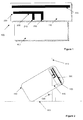
- Figure 1 shows a plan view of an antenna 100 according to an embodiment of the invention.
- the antenna 100 is disposed on a substrate 110.
- the substrate comprises an insulating material.
- the antenna is positioned slightly above a ground plane 400.
- the ground plane is formed from a circuit board housing components of a portable telephone.
- the antenna 100 may be formed integrally with the ground plane 400.
- the antenna 100 comprises two distinct antenna elements 200, 300 arranged to be coplanar. Elements 200 and 300 are created on the substrate using standard techniques. Such techniques may include printing using a suitable conductive ink, or deposition, or using a metal removing process such as etching.
- Element 200 is a Planar Inverted F Antenna (PIFA). It is a conventional quarter wavelength ( ⁇ /4) PIFA and comprises a feed point 210, a ground stub connection 220 and a radiating portion 230. 'Quarter wavelength' refers to the wavelength of intended operation of the antenna, and so the PIFA is dimensioned in the usual way depending on its frequency of operation.
- PIFA Planar Inverted F Antenna
- antenna element 300 Positioned apart from the PIFA, and electrically insulated from it, is antenna element 300.
- Element 300 is a patch antenna, specifically a half wavelength ( ⁇ /2) patch antenna.
- One of the open ends of ( ⁇ /2) patch antenna is aligned with the open end of the PIFA for efficient coupling between them. This allows the field distributions including orientation to substantially align.
- the aligned fields may be electrical or magnetic or both.
- the mode of operation of antenna 100 comprising elements 200 and 300 is different to the mode of operation of either of the elements individually. It is, however, instructive to examine the operation of elements 200 and 300 alone, and then consider their mutual interaction.
- the polarisation of the PIFA 200 is determined by the orientation of the radiating part 230. If the PIFA as shown were positioned horizontally inside a portable telephone then in use, the radiating part 230 would be positioned at an angle of 30° to the vertical, which helps to achieve the aim of near-vertical polarisation. Figure 2 illustrates this situation.
- the PIFA 200 is an unbalanced antenna, which means that when transmitting, a relatively large current is induced in the ground plane 400.
- this current flows up the ground plane 400 in a direction parallel with the feed point 210 and ground stub 220.
- this current has a pronounced effect on the polarisation of the antenna, as it accounts for a large proportion of the transmitted energy.
- a problem is that the direction of this current flow is shifted 90° from the desired polarisation as defined by radiating element 230.
- the current flowing in the ground plane 400 is easily influenced by external structures, such as the user's hand holding the telephone. Such external factors can de-tune the antenna, and adversely affect its performance.
- PIFA antennas offer advantages in that they are compact, and offer good impedance matching characteristics, but being unbalanced, they can suffer from external influences, and it can be difficult to assess their exact polarisation due to the current flow in the ground plane.
- the patch element 300 is a simple linear construction having an electrical length of half a wavelength at the desired frequency of operation.
- Element 300 is a balanced antenna.
- Balanced antennas do not induce current in a ground plane in the same way as described for the PIFA 200.
- balanced antennas are not widely used as internal antennas for portable telephones. This is, for example, because a patch antenna, behaving electrically as a dipole, in close proximity to a ground plane has a relatively low input impedance which makes it difficult to match to the standard 50 ⁇ impedance found throughout the RF portion of the telephone. Another reason is that a half wavelength microstrip patch antenna, which has better impedance characteristics, tends to be too large to incorporate into a portable telephone.
- the polarisation is determined essentially by the direction of current flow in the antenna 300.
- the antenna 100 is able to benefit from some of the advantages of both types of antenna, while avoiding some of the drawbacks of each.
- the PIFA 200 is directly electrically driven at the feed point 210 from the output of a transmitter in the RF section of a portable telephone.
- the ground stub portion is connected, directly or indirectly, to the ground plane 400.
- the PIFA offers good impedance matching to the transmitter, and as such, the transfer of energy to the antenna 100 can be optimised.
- the PIFA is not intended to be the primary radiator of energy from the telephone.
- the primary purpose of the PIFA 200 in antenna 100 is to excite the patch element 300.
- Patch element 300 is not electrically connected to the PIFA 200. It is driven electromagnetically, or parasitically, by the PIFA 200. In this way, the current induced in the patch element 300 flows along the length of the patch and this direction establishes the polarisation of the antenna 100. As stated previously, the direction of current flow in the primary radiating element 300 relates directly to the polarisation of the antenna.
- patch element 300 is the primary radiator of energy from the antenna, the problem of current flow in the ground plane is greatly mitigated. This leads to a reduced susceptibility to problems of detuning and energy loss caused by interaction with a user's hand, for instance. It also leads to a more defined and predictable polarisation, as the impact of current flow in the ground plane on the angle of polarisation is at least reduced.
- the distance of the patch 300 from the PIFA 200 is close enough to ensure good coupling between the two elements.
- a distance between the two elements of between ⁇ /30 and ⁇ /15 is found to give satisfactory performance.
- simple experimentation in each case will reveal the optimum separation.
- the space constraints imposed by placement in a portable telephone may well dictate the achievable separation.
- the patch element 300 is positioned at 30° from the vertical. This orientation approximates to true vertical polarisation, at least for the purposes of comparative measurements.
- the telephone 150 includes antenna 100.
- the horizontal 500 and vertical 510 axes are shown for reference.
- the telephone 150 is oriented at an angle 530 of 60° to the vertical axis 510.
- the antenna 100, and particularly element 300 are inclined at an angle 520 of 30° to the vertical axis 510.
- the two antenna elements can be disposed on different planes, rather than the single plane disclosed in Figure 1.
- the two antenna elements can be disposed on different planes, rather than the single plane disclosed in Figure 1.
- the physical constraints of a particular implementation will often dictate the optimum configuration.
- one antenna element for example the PIFA 200
- the patch 300 is disposed on an inner surface of a cover of the telephone.
- the two elements are positioned in a defined spaced relationship which ensures that the appropriate degree of coupling is achieved.
- the two elements of the antenna may be arranged on opposing sides of the same printed circuit board (PCB).
- PCB printed circuit board
- the patch element may be configured in different ways.
- the skilled man will be aware of different configurations for patch antennas.
- An example of a suitable patch antenna has a resonant frequency defined by the length of one side of a square or rectangle of conductive material.
- a particular application for antennas according to embodiments of the invention is for use in portable telephone handsets operable according to the Wideband Code Division Multiple Access (WCDMA) standard.
- WCDMA Wideband Code Division Multiple Access
- This standard defines transmit (TX) and receive (RX) bands running from 1920-1980 MHz and 2110-2170 MHz respectively.
- TX and RX bands running from 1920-1980 MHz and 2110-2170 MHz respectively.
- the relatively wide separation between the TX and RX bands makes it difficult to provide an antenna that has both a wide enough impedance bandwidth and sufficiently high PAG.
- Figure 3 shows a frequency response plot and associated Smith chart recorded for an antenna according to an embodiment of the invention.
- the frequency response plot shows two distinct peaks in the performance, and a useful bandwidth running from 1830 MHz to 2465 MHz, which is more than adequate for use with the TX and RX bands of WCDMA.
- the antenna characterised by the data of Figure 3 also operates at a frequency making it operable according to the Bluetooth communication standard.
- the Smith chart of Figure 3 shows the characteristic loop of a broadband antenna around the centre point of the chart.
- Figures 4 and 5 illustrate test measurements taken for vertical and horizontal polarisation respectively using a test phone incorporating an antenna according to an embodiment of the invention.
- the plots show measurements taken at the extremes of the frequency bands of WCDMA.
- the table below shows typical measured PAG values for various antenna types measured using the test setup as illustrated in Figure 2 together with an artificial head.
- the values for an antenna according to an embodiment of the invention are derived from Figures 4 and 5.
- the phone was placed in the same position - running from ear to mouth and touching the cheek at the centre.
- the table gives PAG figures in dBi, i.e. dB relative to an ideal isotropic radiator. As such, the higher (less negative) the PAG figure is, the better.
- the PAG figures are given at the extremes of the TX and RX bands for WCDMA, and then the final column gives an average of all the figures.
- an antenna according to an embodiment of the invention offers typical improvements in PAG of 3.6dB when compared to a PIFA, 1.5dB compared to a whip antenna, and 2dB compared to a helical antenna.
- any reference to transmission from the antenna is also intended to include, where appropriate, reception by the antenna. This is due to the inherent reciprocity of antennas.
- the present invention includes any novel feature or combination of features disclosed herein either explicitly or any generalisation thereof irrespective of whether or not it relates to the claimed invention or mitigates any or all of the problems addressed.
Abstract
Description
- This invention relates to an antenna. The antenna has a relatively high Pattern Averaged Gain (PAG) figure, and finds particular utility in portable wireless devices such as portable telephones.
- PAG is one of several metrics that can be used to characterise antennas. All antennas radiate energy, to a greater or lesser degree, in one or more directions. PAG is one measure of the average transmission characteristics averaged over a full 360° surrounding the antenna. The better the PAG figure, the better the overall transfer of energy from the transmitter via the antenna.
- PAG is normally calculated to take into account the dominant polarisation intended for a given antenna. For instance, in mobile telephony, the antenna at a Base Station (BS) is generally vertically polarised, and in order to optimise performance, the antenna at the Mobile Station (MS) should be vertically polarised also. However, different people hold their MSs differently, and the relative polarisation can differ depending on exactly what position the telephone is held in and whether the MS is held in the left or right hand.
- To facilitate comparison between different antennas, during empirical measurements, the MS is arranged so that it is positioned next to a dummy head (to mimic the user's head), and inclined at 60° to the vertical. All PAG measurements and comparisons referred to in this specification were made in this way.
- Portable telephones communicate with remote base stations via signals transmitted and received from one or more antennas forming part of the Radio Frequency (RF) circuitry of the telephone. Prior art telephones use a wide variety of different types of antenna depending on a number of factors including size of telephone, cost, performance and bandwidth.
- Older portable telephones, and some new ones, use retractable or telescopic whip antennas almost exclusively. Later telephones typically use helical stub antennas or internal planar antennas.
- A problem with prior art antennas is their relatively low PAG figures. This effectively means that for a given amount of power input to the antenna, a relatively low power signal is emitted from the antenna (when compared to embodiments of the invention).
- The transmitter accounts for the bulk of the power consumed by a portable telephone. For this reason, manufacturers often quote several figures for battery life, depending on what proportion of the time the telephone is transmitting rather than being in a standby mode waiting for a call to be made or received. It is clear from such figures what impact transmission can have on battery life, and hence talk time.
- Improvements in PAG for a given telephone by use of a different antenna can therefore have a direct measurable effect on talk time and battery life. Improved PAG can also improve call quality, particularly in areas of poor reception, as the benefits of PAG apply equally well to reception as well as transmission.
- According to a first aspect of the present invention there is provided an antenna comprising: a first element comprising an unbalanced antenna having a feed point; and a second element, having a spaced relationship with the first element, and comprising a balanced antenna arranged to be electromagnetically coupled to the first element such that the field distributions of each are substantially aligned for efficient coupling.
- An antenna according to embodiments of the invention has a higher PAG figure than an antenna consisting of only one of the two elements making up the antenna. A higher PAG contributes directly to longer talk time/battery life, as less power needs to be transmitted from the antenna to achieve a desired signal strength at a given remote point.
- Such performance also means that such an antenna, operating in receive mode, is better able to receive signals of a given strength, than an antenna having a lower PAG figure.
- The term 'feed point' when used in relation to embodiments of the invention is intended to refer to a common electrical connection used to transfer energy into and out of the antenna.
- An antenna according to embodiments of the invention matches more closely the ideal of vertical polarisation than some prior art internal antennas, particularly PIFAs. This has the advantage that the transfer of energy between the transmitter and receiver can be maximised.
- An antenna according to embodiments of the invention can be used in handsets operable according to the WCDMA standard, which has a relatively wide separation between TX and RX bands. The wide bandwidth of operation of such an antenna ensures that the PAG figure can be maintained across the entire bandwidth of operation of the antenna.
- Since the operational frequency used by devices operating according to the Bluetooth standard is relatively near to the operational frequencies of WCDMA, it may be possible to use such antennas for communication using Bluetooth.
- Antennas according to embodiments of the invention comprise a directly driven unbalanced antenna and an electromagnetically coupled balanced antenna. Preferred embodiments use a PIFA as the unbalanced antenna, and a half wavelength microstrip or patch antenna for the balanced antenna. A half wavelength patch antenna is found to behave electrically as though it were a half wavelength dipole antenna.
- Forms of antenna other than those specifically disclosed may also be suitable.
- Antennas according to embodiments of the invention benefit from advantages such as the good impedance matching of unbalanced antennas, and good polarisation characteristics of balanced antennas, without suffering from drawbacks such as the poor impedance matching of balanced antennas, and relatively high induced ground plane current of unbalanced antennas.
- Advantageously, an antenna according to embodiments of the invention can be simply incorporated into a portable telephone, or other wireless communication device. In one embodiment, the antenna can be arranged to be co-planar, with both elements disposed on a common circuit board. In an alternative embodiment, one element can be disposed on a circuit board, and the other element can be disposed on an internal surface of a cover of the telephone. In this way, the spaced relationship between the two elements is achieved when the cover is attached to the telephone body during assembly of the telephone.
- In a further embodiment, the two elements of the antenna may be disposed on opposing surfaces of the same Printed Circuit Board (PCB).
- For a better understanding of the present invention, and to understand how the same may be brought into effect, the invention will now be described, by way of example only, with reference to the appended drawings in which:
- Figure 1 shows a preferred embodiment of the invention;
- Figure 2 shows the orientation of the antenna of Figure 1 in use;
- Figure 3 shows a frequency response plot and a Smith chart for the antenna of Figure 1;
- Figure 4 shows the measured radiation pattern (vertical polarisation) of an antenna according to an embodiment of the invention using a standard artificial head; and
- Figure 5 shows the measured radiation pattern (horizontal polarisation) of an antenna according to an embodiment of the invention using a standard artificial head.
-
- Figure 1 shows a plan view of an
antenna 100 according to an embodiment of the invention. Theantenna 100 is disposed on asubstrate 110. The substrate comprises an insulating material. The antenna is positioned slightly above aground plane 400. The ground plane is formed from a circuit board housing components of a portable telephone. Theantenna 100 may be formed integrally with theground plane 400. - The
antenna 100 comprises twodistinct antenna elements Elements -
Element 200 is a Planar Inverted F Antenna (PIFA). It is a conventional quarter wavelength (λ/4) PIFA and comprises afeed point 210, aground stub connection 220 and aradiating portion 230. 'Quarter wavelength' refers to the wavelength of intended operation of the antenna, and so the PIFA is dimensioned in the usual way depending on its frequency of operation. - Positioned apart from the PIFA, and electrically insulated from it, is
antenna element 300. Element 300 is a patch antenna, specifically a half wavelength (λ/2) patch antenna. One of the open ends of (λ/2) patch antenna is aligned with the open end of the PIFA for efficient coupling between them. This allows the field distributions including orientation to substantially align. The aligned fields may be electrical or magnetic or both. - The mode of operation of
antenna 100, comprisingelements elements - The polarisation of the
PIFA 200 is determined by the orientation of the radiatingpart 230. If the PIFA as shown were positioned horizontally inside a portable telephone then in use, the radiatingpart 230 would be positioned at an angle of 30° to the vertical, which helps to achieve the aim of near-vertical polarisation. Figure 2 illustrates this situation. - The
PIFA 200 is an unbalanced antenna, which means that when transmitting, a relatively large current is induced in theground plane 400. Experiments have shown that this current flows up theground plane 400 in a direction parallel with thefeed point 210 andground stub 220. In effect, this current has a pronounced effect on the polarisation of the antenna, as it accounts for a large proportion of the transmitted energy. A problem is that the direction of this current flow is shifted 90° from the desired polarisation as defined by radiatingelement 230. - The current flowing in the
ground plane 400 is easily influenced by external structures, such as the user's hand holding the telephone. Such external factors can de-tune the antenna, and adversely affect its performance. - PIFA antennas offer advantages in that they are compact, and offer good impedance matching characteristics, but being unbalanced, they can suffer from external influences, and it can be difficult to assess their exact polarisation due to the current flow in the ground plane.
- The
patch element 300 is a simple linear construction having an electrical length of half a wavelength at the desired frequency of operation. -
Element 300 is a balanced antenna. Balanced antennas do not induce current in a ground plane in the same way as described for thePIFA 200. However, balanced antennas are not widely used as internal antennas for portable telephones. This is, for example, because a patch antenna, behaving electrically as a dipole, in close proximity to a ground plane has a relatively low input impedance which makes it difficult to match to the standard 50Ω impedance found throughout the RF portion of the telephone. Another reason is that a half wavelength microstrip patch antenna, which has better impedance characteristics, tends to be too large to incorporate into a portable telephone. - Due to the balanced nature of the
patch 300, and the lack of induced current flow in theground plane 400, the polarisation is determined essentially by the direction of current flow in theantenna 300. - The above has described some of the advantages and disadvantages of balanced and unbalanced antennas, and explains a little of why certain types of antenna have been used in portable telephones.
- The
antenna 100, according to an embodiment of the invention, is able to benefit from some of the advantages of both types of antenna, while avoiding some of the drawbacks of each. - The
PIFA 200 is directly electrically driven at thefeed point 210 from the output of a transmitter in the RF section of a portable telephone. The ground stub portion is connected, directly or indirectly, to theground plane 400. - The PIFA offers good impedance matching to the transmitter, and as such, the transfer of energy to the
antenna 100 can be optimised. The PIFA is not intended to be the primary radiator of energy from the telephone. The primary purpose of thePIFA 200 inantenna 100 is to excite thepatch element 300. -
Patch element 300 is not electrically connected to thePIFA 200. It is driven electromagnetically, or parasitically, by thePIFA 200. In this way, the current induced in thepatch element 300 flows along the length of the patch and this direction establishes the polarisation of theantenna 100. As stated previously, the direction of current flow in theprimary radiating element 300 relates directly to the polarisation of the antenna. - As
patch element 300 is the primary radiator of energy from the antenna, the problem of current flow in the ground plane is greatly mitigated. This leads to a reduced susceptibility to problems of detuning and energy loss caused by interaction with a user's hand, for instance. It also leads to a more defined and predictable polarisation, as the impact of current flow in the ground plane on the angle of polarisation is at least reduced. - The distance of the
patch 300 from thePIFA 200 is close enough to ensure good coupling between the two elements. In experiments, a distance between the two elements of between λ/30 and λ/15 is found to give satisfactory performance. However, simple experimentation in each case will reveal the optimum separation. The space constraints imposed by placement in a portable telephone may well dictate the achievable separation. - Thus, when the portable telephone is held at a nominal 60° from the vertical, the
patch element 300 is positioned at 30° from the vertical. This orientation approximates to true vertical polarisation, at least for the purposes of comparative measurements. - This situation is pictured in Figure 2. The
telephone 150 includesantenna 100. The horizontal 500 and vertical 510 axes are shown for reference. Thetelephone 150 is oriented at anangle 530 of 60° to thevertical axis 510. In this position, which is deemed to represent a realistic orientation for a telephone in use, theantenna 100, and particularlyelement 300, are inclined at anangle 520 of 30° to thevertical axis 510. - In alternative embodiments of the invention, the two antenna elements can be disposed on different planes, rather than the single plane disclosed in Figure 1. There are many ways of achieving a spaced relationship between the two antenna elements whilst maintaining a distance which enables the appropriate degree of electromagnetic coupling to occur. The physical constraints of a particular implementation will often dictate the optimum configuration.
- In a particular embodiment, one antenna element, for example the
PIFA 200, is disposed on a circuit board carrying components of the portable telephone, while thepatch 300 is disposed on an inner surface of a cover of the telephone. In this way, when the telephone cover is attached to the body of the telephone, the two elements are positioned in a defined spaced relationship which ensures that the appropriate degree of coupling is achieved. As in the previous embodiment, there is no direct electrical connection between the two antenna elements. - In an alternative embodiment, the two elements of the antenna may be arranged on opposing sides of the same printed circuit board (PCB). There is generally more free space on one side of a PCB than the other, and this approach may optimise use of that space.
- In alternative embodiments, the patch element may be configured in different ways. The skilled man will be aware of different configurations for patch antennas. An example of a suitable patch antenna has a resonant frequency defined by the length of one side of a square or rectangle of conductive material.
- A particular application for antennas according to embodiments of the invention is for use in portable telephone handsets operable according to the Wideband Code Division Multiple Access (WCDMA) standard. This standard defines transmit (TX) and receive (RX) bands running from 1920-1980 MHz and 2110-2170 MHz respectively. The relatively wide separation between the TX and RX bands makes it difficult to provide an antenna that has both a wide enough impedance bandwidth and sufficiently high PAG.
- Prior art antennas suitable for such operation generally compromise the PAG performance in order to operate over the required bandwidth.
- Figure 3 shows a frequency response plot and associated Smith chart recorded for an antenna according to an embodiment of the invention. The frequency response plot shows two distinct peaks in the performance, and a useful bandwidth running from 1830 MHz to 2465 MHz, which is more than adequate for use with the TX and RX bands of WCDMA.
- The antenna characterised by the data of Figure 3 also operates at a frequency making it operable according to the Bluetooth communication standard.
- The Smith chart of Figure 3 shows the characteristic loop of a broadband antenna around the centre point of the chart.
- Figures 4 and 5 illustrate test measurements taken for vertical and horizontal polarisation respectively using a test phone incorporating an antenna according to an embodiment of the invention. The plots show measurements taken at the extremes of the frequency bands of WCDMA.
- The plots show a better performance for vertical polarisation, which is the desired result. As base station antennas are generally vertically polarised, this is the preferred mode of operation of antennas in portable devices.
- The table below shows typical measured PAG values for various antenna types measured using the test setup as illustrated in Figure 2 together with an artificial head. The values for an antenna according to an embodiment of the invention are derived from Figures 4 and 5.
Antenna type Pattern Averaged Gain (PAG) (dBi) 1920 MHz 1980 MHz 2110 MHz 2170 MHz Average Antenna pictured in Figure 1 -3.27 -2.92 -2.92 -2.97 -3.02 PIFA -7.45 -6.60 -5.89 -6.57 -6.63 Extended whip -4.30 -5.10 -4.20 -4.60 -4.55 Helical Antenna -6.10 -5.30 -4.20 -4.50 -5.05 - For each test, the phone was placed in the same position - running from ear to mouth and touching the cheek at the centre.
- The table gives PAG figures in dBi, i.e. dB relative to an ideal isotropic radiator. As such, the higher (less negative) the PAG figure is, the better. The PAG figures are given at the extremes of the TX and RX bands for WCDMA, and then the final column gives an average of all the figures.
- From a comparison of the figures, it can be seen that an antenna according to an embodiment of the invention offers typical improvements in PAG of 3.6dB when compared to a PIFA, 1.5dB compared to a whip antenna, and 2dB compared to a helical antenna.
- An improvement of 3dB in PAG equates to twice as much power being received at a given distance from the transmitting antenna. The corollary of this means that to ensure that a given power level is received at a given point, only half as much power needs to be transmitted in the first instance. Such a saving in transmission power has a noticeable effect on battery life, and hence the talk time available to the user from a given battery.
- In the context of the present invention, any reference to transmission from the antenna is also intended to include, where appropriate, reception by the antenna. This is due to the inherent reciprocity of antennas.
- The present invention includes any novel feature or combination of features disclosed herein either explicitly or any generalisation thereof irrespective of whether or not it relates to the claimed invention or mitigates any or all of the problems addressed.
Claims (9)
- An antenna comprising:a first element comprising an unbalanced antenna having a feed point; anda second element, having a spaced relationship with the first element, and comprising a balanced antenna arranged to be electromagnetically coupled to the first element such that the field distributions of each are substantially aligned for efficient coupling.
- An antenna as claimed in claim 1 wherein the first element is a Planar Inverted-F Antenna (PIFA).
- An antenna as claimed in claim 2 wherein the PIFA is a quarter-wavelength PIFA.
- An antenna as claimed in any one of the preceding claims wherein the second element is a patch antenna.
- An antenna as claimed in claim 4 wherein the second element is a half-wavelength patch antenna.
- A portable telephone comprising an antenna as claimed in any one of the preceding claims.
- A portable telephone as claimed in claim 6 comprising a cover including the second element.
- A portable telephone as claimed in claim 6 or 7 wherein the first element is disposed on a circuit board housed within the portable telephone.
- A portable telephone as claimed in any one of claims 6 to 8 operable according to the WCDMA communication standard.
Applications Claiming Priority (2)
| Application Number | Priority Date | Filing Date | Title |
|---|---|---|---|
| GB0116001 | 2001-06-29 | ||
| GB0116001A GB2377082A (en) | 2001-06-29 | 2001-06-29 | Two element antenna system |
Publications (3)
| Publication Number | Publication Date |
|---|---|
| EP1271690A2 true EP1271690A2 (en) | 2003-01-02 |
| EP1271690A3 EP1271690A3 (en) | 2003-11-05 |
| EP1271690B1 EP1271690B1 (en) | 2006-12-13 |
Family
ID=9917665
Family Applications (1)
| Application Number | Title | Priority Date | Filing Date |
|---|---|---|---|
| EP02254296A Expired - Lifetime EP1271690B1 (en) | 2001-06-29 | 2002-06-20 | An antenna |
Country Status (5)
| Country | Link |
|---|---|
| US (1) | US7061430B2 (en) |
| EP (1) | EP1271690B1 (en) |
| AT (1) | ATE348418T1 (en) |
| DE (1) | DE60216670T2 (en) |
| GB (1) | GB2377082A (en) |
Cited By (8)
| Publication number | Priority date | Publication date | Assignee | Title |
|---|---|---|---|---|
| EP1439603A1 (en) | 2003-01-15 | 2004-07-21 | Filtronic LK Oy | Antenna element as part of the cover of a radio device |
| US6937196B2 (en) | 2003-01-15 | 2005-08-30 | Filtronic Lk Oy | Internal multiband antenna |
| US7126547B2 (en) | 2004-09-06 | 2006-10-24 | Samsung Electro-Mechanics Co., Ltd. | Antenna module and electronic apparatus having the same |
| EP1933414A3 (en) * | 2006-12-12 | 2008-09-24 | Alps Electric Co., Ltd. | Antenna device having good symmetry of directional characteristics |
| US7501983B2 (en) | 2003-01-15 | 2009-03-10 | Lk Products Oy | Planar antenna structure and radio device |
| EP2704516A2 (en) * | 2011-06-03 | 2014-03-05 | Huawei Device Co., Ltd. | Wireless terminal |
| US9673507B2 (en) | 2011-02-11 | 2017-06-06 | Pulse Finland Oy | Chassis-excited antenna apparatus and methods |
| US9917346B2 (en) | 2011-02-11 | 2018-03-13 | Pulse Finland Oy | Chassis-excited antenna apparatus and methods |
Families Citing this family (40)
| Publication number | Priority date | Publication date | Assignee | Title |
|---|---|---|---|---|
| EP1563570A1 (en) * | 2002-11-07 | 2005-08-17 | Fractus, S.A. | Integrated circuit package including miniature antenna |
| US20050099335A1 (en) * | 2003-11-10 | 2005-05-12 | Shyh-Jong Chung | Multiple-frequency antenna structure |
| FI20055420A0 (en) | 2005-07-25 | 2005-07-25 | Lk Products Oy | Adjustable multi-band antenna |
| FI119009B (en) | 2005-10-03 | 2008-06-13 | Pulse Finland Oy | Multiple-band antenna |
| FI118782B (en) | 2005-10-14 | 2008-03-14 | Pulse Finland Oy | Adjustable antenna |
| US7548208B2 (en) * | 2006-02-24 | 2009-06-16 | Palm, Inc. | Internal diversity antenna architecture |
| US8618990B2 (en) | 2011-04-13 | 2013-12-31 | Pulse Finland Oy | Wideband antenna and methods |
| FI20075269A0 (en) | 2007-04-19 | 2007-04-19 | Pulse Finland Oy | Method and arrangement for antenna matching |
| FI120427B (en) | 2007-08-30 | 2009-10-15 | Pulse Finland Oy | Adjustable multiband antenna |
| US7642966B2 (en) * | 2008-03-14 | 2010-01-05 | Sony Ericsson Mobile Communications Ab | Carrier and device |
| CN101853981A (en) * | 2009-04-03 | 2010-10-06 | 深圳富泰宏精密工业有限公司 | Multifrequency antenna and wireless communication device applying same |
| FI20096134A0 (en) | 2009-11-03 | 2009-11-03 | Pulse Finland Oy | Adjustable antenna |
| FI20096251A0 (en) | 2009-11-27 | 2009-11-27 | Pulse Finland Oy | MIMO antenna |
| US8847833B2 (en) | 2009-12-29 | 2014-09-30 | Pulse Finland Oy | Loop resonator apparatus and methods for enhanced field control |
| TWI425713B (en) * | 2010-02-12 | 2014-02-01 | First Int Computer Inc | Three-band antenna device with resonance generation |
| FI20105158A (en) | 2010-02-18 | 2011-08-19 | Pulse Finland Oy | SHELL RADIATOR ANTENNA |
| US9406998B2 (en) | 2010-04-21 | 2016-08-02 | Pulse Finland Oy | Distributed multiband antenna and methods |
| FI20115072A0 (en) | 2011-01-25 | 2011-01-25 | Pulse Finland Oy | Multi-resonance antenna, antenna module and radio unit |
| US9799944B2 (en) * | 2011-06-17 | 2017-10-24 | Microsoft Technology Licensing, Llc | PIFA array |
| US8866689B2 (en) | 2011-07-07 | 2014-10-21 | Pulse Finland Oy | Multi-band antenna and methods for long term evolution wireless system |
| US9450291B2 (en) | 2011-07-25 | 2016-09-20 | Pulse Finland Oy | Multiband slot loop antenna apparatus and methods |
| US9123990B2 (en) | 2011-10-07 | 2015-09-01 | Pulse Finland Oy | Multi-feed antenna apparatus and methods |
| US9531058B2 (en) | 2011-12-20 | 2016-12-27 | Pulse Finland Oy | Loosely-coupled radio antenna apparatus and methods |
| US9484619B2 (en) | 2011-12-21 | 2016-11-01 | Pulse Finland Oy | Switchable diversity antenna apparatus and methods |
| US8988296B2 (en) | 2012-04-04 | 2015-03-24 | Pulse Finland Oy | Compact polarized antenna and methods |
| US9979078B2 (en) | 2012-10-25 | 2018-05-22 | Pulse Finland Oy | Modular cell antenna apparatus and methods |
| US10069209B2 (en) | 2012-11-06 | 2018-09-04 | Pulse Finland Oy | Capacitively coupled antenna apparatus and methods |
| US9647338B2 (en) | 2013-03-11 | 2017-05-09 | Pulse Finland Oy | Coupled antenna structure and methods |
| US10079428B2 (en) | 2013-03-11 | 2018-09-18 | Pulse Finland Oy | Coupled antenna structure and methods |
| TWI539660B (en) * | 2013-05-03 | 2016-06-21 | 宏碁股份有限公司 | Mobile device |
| US9634383B2 (en) | 2013-06-26 | 2017-04-25 | Pulse Finland Oy | Galvanically separated non-interacting antenna sector apparatus and methods |
| US9680212B2 (en) | 2013-11-20 | 2017-06-13 | Pulse Finland Oy | Capacitive grounding methods and apparatus for mobile devices |
| US9590308B2 (en) | 2013-12-03 | 2017-03-07 | Pulse Electronics, Inc. | Reduced surface area antenna apparatus and mobile communications devices incorporating the same |
| US9350081B2 (en) | 2014-01-14 | 2016-05-24 | Pulse Finland Oy | Switchable multi-radiator high band antenna apparatus |
| US9401738B2 (en) * | 2014-07-15 | 2016-07-26 | Mediatek Singapore Pte. Ltd. | Method for simplified closed-loop antenna tuning |
| US9973228B2 (en) | 2014-08-26 | 2018-05-15 | Pulse Finland Oy | Antenna apparatus with an integrated proximity sensor and methods |
| US9948002B2 (en) | 2014-08-26 | 2018-04-17 | Pulse Finland Oy | Antenna apparatus with an integrated proximity sensor and methods |
| US9722308B2 (en) | 2014-08-28 | 2017-08-01 | Pulse Finland Oy | Low passive intermodulation distributed antenna system for multiple-input multiple-output systems and methods of use |
| US9906260B2 (en) | 2015-07-30 | 2018-02-27 | Pulse Finland Oy | Sensor-based closed loop antenna swapping apparatus and methods |
| DE102016011815B3 (en) | 2016-10-05 | 2018-02-15 | IAD Gesellschaft für Informatik, Automatisierung und Datenverarbeitung mbH | Control gear with staggered overvoltage and overcurrent protection for the control of intelligent light sources and devices as well as light sources with this control gear |
Citations (3)
| Publication number | Priority date | Publication date | Assignee | Title |
|---|---|---|---|---|
| EP0923158A2 (en) * | 1997-12-10 | 1999-06-16 | Nokia Mobile Phones Ltd. | Antenna |
| US5966097A (en) * | 1996-06-03 | 1999-10-12 | Mitsubishi Denki Kabushiki Kaisha | Antenna apparatus |
| EP1102347A2 (en) * | 1999-11-17 | 2001-05-23 | Nokia Mobile Phones Ltd. | Integrated antenna ground plate and EMC shield structure |
Family Cites Families (5)
| Publication number | Priority date | Publication date | Assignee | Title |
|---|---|---|---|---|
| US4070676A (en) * | 1975-10-06 | 1978-01-24 | Ball Corporation | Multiple resonance radio frequency microstrip antenna structure |
| JP3326935B2 (en) * | 1993-12-27 | 2002-09-24 | 株式会社日立製作所 | Small antenna for portable radio |
| JPH08330827A (en) * | 1995-05-29 | 1996-12-13 | Mitsubishi Electric Corp | Antenna system |
| US6016126A (en) * | 1998-05-29 | 2000-01-18 | Ericsson Inc. | Non-protruding dual-band antenna for communications device |
| US6225951B1 (en) * | 2000-06-01 | 2001-05-01 | Telefonaktiebolaget L.M. Ericsson | Antenna systems having capacitively coupled internal and retractable antennas and wireless communicators incorporating same |
-
2001
- 2001-06-29 GB GB0116001A patent/GB2377082A/en not_active Withdrawn
-
2002
- 2002-06-20 EP EP02254296A patent/EP1271690B1/en not_active Expired - Lifetime
- 2002-06-20 DE DE60216670T patent/DE60216670T2/en not_active Expired - Lifetime
- 2002-06-20 AT AT02254296T patent/ATE348418T1/en not_active IP Right Cessation
- 2002-06-27 US US10/180,122 patent/US7061430B2/en not_active Expired - Lifetime
Patent Citations (3)
| Publication number | Priority date | Publication date | Assignee | Title |
|---|---|---|---|---|
| US5966097A (en) * | 1996-06-03 | 1999-10-12 | Mitsubishi Denki Kabushiki Kaisha | Antenna apparatus |
| EP0923158A2 (en) * | 1997-12-10 | 1999-06-16 | Nokia Mobile Phones Ltd. | Antenna |
| EP1102347A2 (en) * | 1999-11-17 | 2001-05-23 | Nokia Mobile Phones Ltd. | Integrated antenna ground plate and EMC shield structure |
Non-Patent Citations (1)
| Title |
|---|
| SAKAI S ET AL: "Directivity gain enhancement of small antenna by parasitic patch" ANTENNAS AND PROPAGATION SOCIETY INTERNATIONAL SYMPOSIUM, 1998. IEEE ATLANTA, GA, USA 21-26 JUNE 1998, NEW YORK, NY, USA,IEEE, US, 21 June 1998 (1998-06-21), pages 320-323, XP010291893 ISBN: 0-7803-4478-2 * |
Cited By (11)
| Publication number | Priority date | Publication date | Assignee | Title |
|---|---|---|---|---|
| EP1439603A1 (en) | 2003-01-15 | 2004-07-21 | Filtronic LK Oy | Antenna element as part of the cover of a radio device |
| US6937196B2 (en) | 2003-01-15 | 2005-08-30 | Filtronic Lk Oy | Internal multiband antenna |
| US7501983B2 (en) | 2003-01-15 | 2009-03-10 | Lk Products Oy | Planar antenna structure and radio device |
| US7126547B2 (en) | 2004-09-06 | 2006-10-24 | Samsung Electro-Mechanics Co., Ltd. | Antenna module and electronic apparatus having the same |
| DE102004052763B4 (en) * | 2004-09-06 | 2007-03-08 | Samsung Electro-Mechanics Co., Ltd., Suwon | Antenna module and an antenna device containing electronic device |
| EP1933414A3 (en) * | 2006-12-12 | 2008-09-24 | Alps Electric Co., Ltd. | Antenna device having good symmetry of directional characteristics |
| US7746286B2 (en) | 2006-12-12 | 2010-06-29 | Alps Electric Co., Ltd. | Antenna device having good symmetry of directional characteristics |
| US9673507B2 (en) | 2011-02-11 | 2017-06-06 | Pulse Finland Oy | Chassis-excited antenna apparatus and methods |
| US9917346B2 (en) | 2011-02-11 | 2018-03-13 | Pulse Finland Oy | Chassis-excited antenna apparatus and methods |
| EP2704516A2 (en) * | 2011-06-03 | 2014-03-05 | Huawei Device Co., Ltd. | Wireless terminal |
| EP2704516A4 (en) * | 2011-06-03 | 2014-12-24 | Huawei Device Co Ltd | Wireless terminal |
Also Published As
| Publication number | Publication date |
|---|---|
| DE60216670D1 (en) | 2007-01-25 |
| EP1271690B1 (en) | 2006-12-13 |
| GB0116001D0 (en) | 2001-08-22 |
| ATE348418T1 (en) | 2007-01-15 |
| US20030016175A1 (en) | 2003-01-23 |
| EP1271690A3 (en) | 2003-11-05 |
| DE60216670T2 (en) | 2007-10-04 |
| GB2377082A (en) | 2002-12-31 |
| US7061430B2 (en) | 2006-06-13 |
Similar Documents
| Publication | Publication Date | Title |
|---|---|---|
| EP1271690B1 (en) | An antenna | |
| US6215447B1 (en) | Antenna assembly for communications devices | |
| US7058434B2 (en) | Mobile communication | |
| US7230574B2 (en) | Oriented PIFA-type device and method of use for reducing RF interference | |
| KR100467569B1 (en) | Microstrip patch antenna for transmitting and receiving | |
| US6268831B1 (en) | Inverted-f antennas with multiple planar radiating elements and wireless communicators incorporating same | |
| US7782257B2 (en) | Multi-band internal antenna of symmetry structure having stub | |
| US6326927B1 (en) | Capacitively-tuned broadband antenna structure | |
| US8482464B2 (en) | Mobile communication device | |
| US6225951B1 (en) | Antenna systems having capacitively coupled internal and retractable antennas and wireless communicators incorporating same | |
| US20040145522A1 (en) | Planar multiple band omni radiation pattern antenna | |
| TW200631234A (en) | A planar inverted-f antenna | |
| US20110128193A1 (en) | Card device for wireless communication | |
| EP1353399A1 (en) | Built-in anenna of portable radio apparatus | |
| US6667718B2 (en) | Microstrip dual band antenna | |
| US20020123312A1 (en) | Antenna systems including internal planar inverted-F Antenna coupled with external radiating element and wireless communicators incorporating same | |
| US7482984B2 (en) | Hoop antenna | |
| KR100365780B1 (en) | The inside single band antenna apparatus of a portable communication terminal and method for operating together the whip antenna | |
| CN202817178U (en) | Dual-frequency monopole antenna and its mobile terminal | |
| KR20010003035A (en) | Printing-Type Inverted F Antenna | |
| WO2010071265A1 (en) | Built-in antenna which supports broadband impedance matching and has feeding patch coupled to substrate | |
| TWI747538B (en) | Antenna system | |
| US20030132881A1 (en) | Double F antenna | |
| JPS5977724A (en) | Portable radio device | |
| KR20080097813A (en) | Portable communication terminal |
Legal Events
| Date | Code | Title | Description |
|---|---|---|---|
| PUAI | Public reference made under article 153(3) epc to a published international application that has entered the european phase |
Free format text: ORIGINAL CODE: 0009012 |
|
| AK | Designated contracting states |
Kind code of ref document: A2 Designated state(s): AT BE CH CY DE DK ES FI FR GB GR IE IT LI LU MC NL PT SE TR |
|
| AX | Request for extension of the european patent |
Free format text: AL;LT;LV;MK;RO;SI |
|
| PUAL | Search report despatched |
Free format text: ORIGINAL CODE: 0009013 |
|
| AK | Designated contracting states |
Kind code of ref document: A3 Designated state(s): AT BE CH CY DE DK ES FI FR GB GR IE IT LI LU MC NL PT SE TR |
|
| AX | Request for extension of the european patent |
Extension state: AL LT LV MK RO SI |
|
| 17P | Request for examination filed |
Effective date: 20040504 |
|
| AKX | Designation fees paid |
Designated state(s): AT BE CH CY DE DK ES FI FR GB GR IE IT LI LU MC NL PT SE TR |
|
| 17Q | First examination report despatched |
Effective date: 20040910 |
|
| GRAP | Despatch of communication of intention to grant a patent |
Free format text: ORIGINAL CODE: EPIDOSNIGR1 |
|
| GRAS | Grant fee paid |
Free format text: ORIGINAL CODE: EPIDOSNIGR3 |
|
| GRAA | (expected) grant |
Free format text: ORIGINAL CODE: 0009210 |
|
| AK | Designated contracting states |
Kind code of ref document: B1 Designated state(s): AT BE CH CY DE DK ES FI FR GB GR IE IT LI LU MC NL PT SE TR |
|
| PG25 | Lapsed in a contracting state [announced via postgrant information from national office to epo] |
Ref country code: IT Free format text: LAPSE BECAUSE OF FAILURE TO SUBMIT A TRANSLATION OF THE DESCRIPTION OR TO PAY THE FEE WITHIN THE PRESCRIBED TIME-LIMIT;WARNING: LAPSES OF ITALIAN PATENTS WITH EFFECTIVE DATE BEFORE 2007 MAY HAVE OCCURRED AT ANY TIME BEFORE 2007. THE CORRECT EFFECTIVE DATE MAY BE DIFFERENT FROM THE ONE RECORDED. Effective date: 20061213 Ref country code: BE Free format text: LAPSE BECAUSE OF FAILURE TO SUBMIT A TRANSLATION OF THE DESCRIPTION OR TO PAY THE FEE WITHIN THE PRESCRIBED TIME-LIMIT Effective date: 20061213 Ref country code: NL Free format text: LAPSE BECAUSE OF FAILURE TO SUBMIT A TRANSLATION OF THE DESCRIPTION OR TO PAY THE FEE WITHIN THE PRESCRIBED TIME-LIMIT Effective date: 20061213 Ref country code: DK Free format text: LAPSE BECAUSE OF FAILURE TO SUBMIT A TRANSLATION OF THE DESCRIPTION OR TO PAY THE FEE WITHIN THE PRESCRIBED TIME-LIMIT Effective date: 20061213 Ref country code: AT Free format text: LAPSE BECAUSE OF FAILURE TO SUBMIT A TRANSLATION OF THE DESCRIPTION OR TO PAY THE FEE WITHIN THE PRESCRIBED TIME-LIMIT Effective date: 20061213 Ref country code: CH Free format text: LAPSE BECAUSE OF FAILURE TO SUBMIT A TRANSLATION OF THE DESCRIPTION OR TO PAY THE FEE WITHIN THE PRESCRIBED TIME-LIMIT Effective date: 20061213 Ref country code: LI Free format text: LAPSE BECAUSE OF FAILURE TO SUBMIT A TRANSLATION OF THE DESCRIPTION OR TO PAY THE FEE WITHIN THE PRESCRIBED TIME-LIMIT Effective date: 20061213 Ref country code: FI Free format text: LAPSE BECAUSE OF FAILURE TO SUBMIT A TRANSLATION OF THE DESCRIPTION OR TO PAY THE FEE WITHIN THE PRESCRIBED TIME-LIMIT Effective date: 20061213 |
|
| REG | Reference to a national code |
Ref country code: GB Ref legal event code: FG4D |
|
| REG | Reference to a national code |
Ref country code: CH Ref legal event code: EP |
|
| REG | Reference to a national code |
Ref country code: IE Ref legal event code: FG4D |
|
| REF | Corresponds to: |
Ref document number: 60216670 Country of ref document: DE Date of ref document: 20070125 Kind code of ref document: P |
|
| PG25 | Lapsed in a contracting state [announced via postgrant information from national office to epo] |
Ref country code: SE Free format text: LAPSE BECAUSE OF FAILURE TO SUBMIT A TRANSLATION OF THE DESCRIPTION OR TO PAY THE FEE WITHIN THE PRESCRIBED TIME-LIMIT Effective date: 20070313 |
|
| PG25 | Lapsed in a contracting state [announced via postgrant information from national office to epo] |
Ref country code: ES Free format text: LAPSE BECAUSE OF FAILURE TO SUBMIT A TRANSLATION OF THE DESCRIPTION OR TO PAY THE FEE WITHIN THE PRESCRIBED TIME-LIMIT Effective date: 20070324 |
|
| PG25 | Lapsed in a contracting state [announced via postgrant information from national office to epo] |
Ref country code: PT Free format text: LAPSE BECAUSE OF FAILURE TO SUBMIT A TRANSLATION OF THE DESCRIPTION OR TO PAY THE FEE WITHIN THE PRESCRIBED TIME-LIMIT Effective date: 20070514 |
|
| NLV1 | Nl: lapsed or annulled due to failure to fulfill the requirements of art. 29p and 29m of the patents act | ||
| ET | Fr: translation filed | ||
| REG | Reference to a national code |
Ref country code: CH Ref legal event code: PL |
|
| PLBE | No opposition filed within time limit |
Free format text: ORIGINAL CODE: 0009261 |
|
| STAA | Information on the status of an ep patent application or granted ep patent |
Free format text: STATUS: NO OPPOSITION FILED WITHIN TIME LIMIT |
|
| 26N | No opposition filed |
Effective date: 20070914 |
|
| PG25 | Lapsed in a contracting state [announced via postgrant information from national office to epo] |
Ref country code: MC Free format text: LAPSE BECAUSE OF NON-PAYMENT OF DUE FEES Effective date: 20070630 |
|
| PG25 | Lapsed in a contracting state [announced via postgrant information from national office to epo] |
Ref country code: GR Free format text: LAPSE BECAUSE OF FAILURE TO SUBMIT A TRANSLATION OF THE DESCRIPTION OR TO PAY THE FEE WITHIN THE PRESCRIBED TIME-LIMIT Effective date: 20070314 |
|
| PG25 | Lapsed in a contracting state [announced via postgrant information from national office to epo] |
Ref country code: IE Free format text: LAPSE BECAUSE OF NON-PAYMENT OF DUE FEES Effective date: 20070620 |
|
| PG25 | Lapsed in a contracting state [announced via postgrant information from national office to epo] |
Ref country code: LU Free format text: LAPSE BECAUSE OF NON-PAYMENT OF DUE FEES Effective date: 20070620 Ref country code: CY Free format text: LAPSE BECAUSE OF FAILURE TO SUBMIT A TRANSLATION OF THE DESCRIPTION OR TO PAY THE FEE WITHIN THE PRESCRIBED TIME-LIMIT Effective date: 20061213 |
|
| PG25 | Lapsed in a contracting state [announced via postgrant information from national office to epo] |
Ref country code: TR Free format text: LAPSE BECAUSE OF FAILURE TO SUBMIT A TRANSLATION OF THE DESCRIPTION OR TO PAY THE FEE WITHIN THE PRESCRIBED TIME-LIMIT Effective date: 20061213 |
|
| REG | Reference to a national code |
Ref country code: GB Ref legal event code: 732E Free format text: REGISTERED BETWEEN 20150910 AND 20150916 |
|
| REG | Reference to a national code |
Ref country code: DE Ref legal event code: R082 Ref document number: 60216670 Country of ref document: DE Representative=s name: BECKER, KURIG, STRAUS, DE Ref country code: DE Ref legal event code: R081 Ref document number: 60216670 Country of ref document: DE Owner name: NOKIA TECHNOLOGIES OY, FI Free format text: FORMER OWNER: NOKIA CORP., 02610 ESPOO, FI |
|
| REG | Reference to a national code |
Ref country code: FR Ref legal event code: PLFP Year of fee payment: 15 |
|
| REG | Reference to a national code |
Ref country code: FR Ref legal event code: TP Owner name: NOKIA TECHNOLOGIES OY, FI Effective date: 20170109 |
|
| REG | Reference to a national code |
Ref country code: FR Ref legal event code: PLFP Year of fee payment: 16 |
|
| REG | Reference to a national code |
Ref country code: FR Ref legal event code: PLFP Year of fee payment: 17 |
|
| REG | Reference to a national code |
Ref country code: GB Ref legal event code: 732E Free format text: REGISTERED BETWEEN 20190124 AND 20190130 |
|
| REG | Reference to a national code |
Ref country code: DE Ref legal event code: R082 Ref document number: 60216670 Country of ref document: DE Representative=s name: BECKER, KURIG, STRAUS, DE Ref country code: DE Ref legal event code: R081 Ref document number: 60216670 Country of ref document: DE Owner name: PROVENANCE ASSET GROUP LLC, PITTSFORD, US Free format text: FORMER OWNER: NOKIA TECHNOLOGIES OY, ESPOO, FI Ref country code: DE Ref legal event code: R082 Ref document number: 60216670 Country of ref document: DE Representative=s name: BECKER & KURIG PARTNERSCHAFT PATENTANWAELTE MB, DE Ref country code: DE Ref legal event code: R082 Ref document number: 60216670 Country of ref document: DE Representative=s name: BECKER & KURIG PARTNERSCHAFT PATENTANWAELTE PA, DE |
|
| PGFP | Annual fee paid to national office [announced via postgrant information from national office to epo] |
Ref country code: FR Payment date: 20210623 Year of fee payment: 20 Ref country code: DE Payment date: 20210628 Year of fee payment: 20 |
|
| PGFP | Annual fee paid to national office [announced via postgrant information from national office to epo] |
Ref country code: GB Payment date: 20210625 Year of fee payment: 20 |
|
| REG | Reference to a national code |
Ref country code: GB Ref legal event code: 732E Free format text: REGISTERED BETWEEN 20220210 AND 20220216 |
|
| REG | Reference to a national code |
Ref country code: DE Ref legal event code: R071 Ref document number: 60216670 Country of ref document: DE |
|
| REG | Reference to a national code |
Ref country code: GB Ref legal event code: PE20 Expiry date: 20220619 |
|
| PG25 | Lapsed in a contracting state [announced via postgrant information from national office to epo] |
Ref country code: GB Free format text: LAPSE BECAUSE OF EXPIRATION OF PROTECTION Effective date: 20220619 |