EP1273269B1 - Implantable screw for stabilising an articulated joint or a bone fracture - Google Patents
Implantable screw for stabilising an articulated joint or a bone fracture Download PDFInfo
- Publication number
- EP1273269B1 EP1273269B1 EP02007793A EP02007793A EP1273269B1 EP 1273269 B1 EP1273269 B1 EP 1273269B1 EP 02007793 A EP02007793 A EP 02007793A EP 02007793 A EP02007793 A EP 02007793A EP 1273269 B1 EP1273269 B1 EP 1273269B1
- Authority
- EP
- European Patent Office
- Prior art keywords
- screw
- bone
- joint
- shaft
- wire rope
- Prior art date
- Legal status (The legal status is an assumption and is not a legal conclusion. Google has not performed a legal analysis and makes no representation as to the accuracy of the status listed.)
- Expired - Lifetime
Links
Images


Classifications
-
- A—HUMAN NECESSITIES
- A61—MEDICAL OR VETERINARY SCIENCE; HYGIENE
- A61B—DIAGNOSIS; SURGERY; IDENTIFICATION
- A61B17/00—Surgical instruments, devices or methods, e.g. tourniquets
- A61B17/56—Surgical instruments or methods for treatment of bones or joints; Devices specially adapted therefor
- A61B17/58—Surgical instruments or methods for treatment of bones or joints; Devices specially adapted therefor for osteosynthesis, e.g. bone plates, screws, setting implements or the like
- A61B17/68—Internal fixation devices, including fasteners and spinal fixators, even if a part thereof projects from the skin
- A61B17/84—Fasteners therefor or fasteners being internal fixation devices
- A61B17/86—Pins or screws or threaded wires; nuts therefor
- A61B17/866—Material or manufacture
-
- A—HUMAN NECESSITIES
- A61—MEDICAL OR VETERINARY SCIENCE; HYGIENE
- A61B—DIAGNOSIS; SURGERY; IDENTIFICATION
- A61B17/00—Surgical instruments, devices or methods, e.g. tourniquets
- A61B17/56—Surgical instruments or methods for treatment of bones or joints; Devices specially adapted therefor
- A61B17/58—Surgical instruments or methods for treatment of bones or joints; Devices specially adapted therefor for osteosynthesis, e.g. bone plates, screws, setting implements or the like
- A61B17/68—Internal fixation devices, including fasteners and spinal fixators, even if a part thereof projects from the skin
- A61B17/84—Fasteners therefor or fasteners being internal fixation devices
- A61B17/86—Pins or screws or threaded wires; nuts therefor
- A61B17/8685—Pins or screws or threaded wires; nuts therefor comprising multiple separate parts
-
- A—HUMAN NECESSITIES
- A61—MEDICAL OR VETERINARY SCIENCE; HYGIENE
- A61B—DIAGNOSIS; SURGERY; IDENTIFICATION
- A61B17/00—Surgical instruments, devices or methods, e.g. tourniquets
- A61B17/56—Surgical instruments or methods for treatment of bones or joints; Devices specially adapted therefor
- A61B17/58—Surgical instruments or methods for treatment of bones or joints; Devices specially adapted therefor for osteosynthesis, e.g. bone plates, screws, setting implements or the like
- A61B17/68—Internal fixation devices, including fasteners and spinal fixators, even if a part thereof projects from the skin
- A61B17/84—Fasteners therefor or fasteners being internal fixation devices
- A61B17/86—Pins or screws or threaded wires; nuts therefor
- A61B17/8625—Shanks, i.e. parts contacting bone tissue
- A61B17/863—Shanks, i.e. parts contacting bone tissue with thread interrupted or changing its form along shank, other than constant taper
Definitions
- the invention relates to an implant for augmenting stabilization of bone joints with little relative movement and for the interfragmentary stabilization of bone fractures, when primarily tensile forces are to be introduced.
- the joints of the body have different degrees of movement. In addition to the joints in the main axes of movement of the extremities and the temporomandibular joint, some of which have relative movements of a considerable extent, there are many joints with a low relative range of motion.
- Typical examples of this are the shoulder joint as a link between the scapula and collarbone (Akromioldavikulargelenk), the articulation between the calf bone and sternum (sternoclavicular joint), the funneldarmbeingel joint (sacroiliac joint), the pubic symphysis, the articulated connections between the tibia and fibula (proximal and distal Tibiofibular joint), the joints between the bones of the hands and tarsals, and the joints between the bones of the metacarpal joints (metacarpal joints) of the metatarsal (metatarsal) joints. Nevertheless, injuries of these joints also lead to many cases severe physical limitations, with painful arthritis developing as a result of residual joint mismatch.
- Therapeutic goal must therefore be the exact reduction of these joints with recovery of the capsular ligament apparatus. This is usually not achievable by a simple suture of the capsular ligament apparatus.
- the seams would not withstand the load, tear out and slide the hinge back into an incongruent misalignment. Rather, the injured joint must be held by a suitable surgical implant in the sense of augmentation in a correct position until the capsular ligament is cured in sufficient strength and can take the necessary forces to guide the joint again.
- a suitable surgical implant in the sense of augmentation in a correct position until the capsular ligament is cured in sufficient strength and can take the necessary forces to guide the joint again.
- unstable fractures in which, after reduction of the fracture, an implant should hold the bone in the correct position until the fracture has healed in sufficient strength.
- a typical representative of the 4th group is the joint plate developed by RAMANZADEH for the stabilization of bursts of the shoulder joint.
- this plate has the disadvantage that the adjustment of a correct congruence of the joint is difficult, and that the axes of rotation of the joint and the implant do not match, whereby the natural joint movement is at least partially blocked
- the invention is therefore based on the object to develop an implant which augments reliably the band joints in joints with little relative movement, but does not or not substantially hinder the natural range of motion of the joint.
- an implantable screw for stabilizing a joint connection or a bone fracture with a flexible shaft in which the flexibility in the shaft area is achieved by a wire rope, a cord, a wire bundle or by threads.
- This design of the implant ensures almost exclusively a transmission of tensile forces, while bending moments, pressure and shear forces are transmitted by the flexible shaft not or only slightly.
- a wire rope, a cord, a wire bundle or threads may be referred to as ropes in terms of their function. While a screw with spiral spring in the shaft area under a tensile force in the longitudinal direction expands, it comes with a rope in the shaft area even under relatively high forces acting not to diverge the ankle fork. In contrast, all other relative movements (rotation of the lateral malleolus and slight translational movements between the tibia and fibula) can be performed without relevant expenditure of force. By using a rope, therefore, the stabilizing function of a natural ligamentous compound can be replaced in an almost physiological manner.
- the use of one or more such screws with Flexible shaft makes it possible to connect the bones involved in an unstable joint connection together so that the natural joint movement is not or only slightly hampered.
- Such a screw allows both bones involved in joint injury or fragments involved in a bone injury to be connected by one or more screws having a flexible shaft.
- This design of the implant ensures almost exclusively a transmission of tensile forces, while bending moments, pressure and shear forces are transmitted by the flexible shaft not or only slightly.
- the screw is preferably mounted so that the screw axis coincides with the direction of the resultant force of the band connection of the joint. In this case, an ideal augmentation of the joint can be achieved.
- the screw is introduced perpendicular to the fracture plane and causes by the tensile force an interfragmentary compression.
- an expansion of the operating room can be limited by the invention.
- the invention is suitable in an advantageous embodiment for so-called minimally invasive implantation.
- the inventive screw for use in surgery can be designed so that mainly tensile forces and no significant bending moments are transmitted.
- the screw according to the invention can be designed so that it can be introduced in the sense of a so-called creeping in the medullary cavity of a fractured bone, and thereby adapts to the most curved contour of the medullary cavity.
- the axial area moment of inertia of the screw is smaller by 30%, preferably more than 50%, than in the case of a screw of the same outer diameter.
- the flexibility is achieved in the shaft area by a wire rope, a wire bundle, a cord or threads.
- the wire rope or the wire bundle is reinforced from the outside by sleeves or a spiral. In the initiation of torsional moments thereby winding of the wire rope or the wire bundle is limited, and thereby the wire rope or the wire bundle stabilized. In addition, depending on the size of the sleeves or the spiral turns and their distance from each other limit the bending movement of the shaft.
- the threaded part has a bone thread.
- the head part has a wrench receptacle and depending on the purpose of the implant has a smooth surface or a bone thread corresponding to the threaded portion or has a bone thread which is larger in diameter and smaller in thread pitch than the bone thread in the threaded portion.
- the implantable screw has wrench receptacles both in the head part and in the threaded part. This makes it possible to attack a stepped wrench synchronously on these wrench shots.
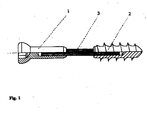
- Fig. 1 shows a bone screw
- the head part 1 and the threaded part 2 are flexibly connected to each other by a wire rope or a wire bundle 3.
- the wire rope or the wire bundle are firmly connected both in the head part and in the thread part by suitable joining methods (e.g., press, gluing, soldering or welding).
- suitable joining methods e.g., press, gluing, soldering or welding.
- the use of a wire rope or a wire bundle allows the introduction of tensile forces and the transmission of torsional moments in the sense of a flexible shaft. Pressure forces, shear forces or bending moments, however, are transmitted only to a small extent.
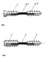
- FIG. 2 shows a bone adjusting screw, which has a bone-threaded head part 4 and a threaded part 5, which are connected to each other in a flexible manner analogous to FIG. 1 by a wire rope or a wire bundle 6.
- the threads of the head and threaded part of the same size and the thread flanks are congruent. In this way, a previously defined distance between 2 bones to be connected is fixed independently of the tightening torque of the screw.
- FIG. 3 shows a bone screw with a thread-carrying head part 7, which are flexibly connected to the threaded part 9 via a wire rope or a wire bundle 8 analogously to FIG.
- the thread on the head part opposite the threaded part has a larger diameter and a smaller thread pitch.
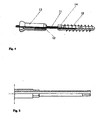
- Fig. 4 shows a screw having on one side a threaded part 10 with bone thread, which is flexibly connected by a wire rope, a wire bundle or a cord 11 with a bolt 12 having a metal or plastic thread.
- a hexagon socket nut 13 is screwed.
- the threaded part with bone thread is screwed into the bone in the sense of a stud. This is done by means of a cannulated socket wrench, which is pushed over the wire rope or the wire bundle or the cord and the bolt and engages the hexagon socket 14 of the threaded part.
- the hexagon socket nut is screwed by means of a cannulated Allen key on the bolt with metal thread.
- the wire rope or wire bundle protruding from the hexagon socket or the protruding cord is shortened with a pair of pliers.
- Fig. 5 shows a step-shaped Allen key.
- the threaded part is cannulated so that the application of the screw can be made via a corresponding guide wire.
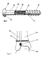
- FIG. 6 shows a bone screw 24, which is equally suitable for the production of implant metal as resorbable or non-resorbable plastics, and which is designed so that the individual components can be produced by casting.
- the flexibility of the shaft is achieved in that it consists of multiple threads 25, which are held either in accordance with the illustration in eyelets 26, 27 alternately in the head part 28 and the threaded part 29 of the screw or firmly anchored in the head part and the threaded part.
- torn syndesmosis ligament connection between the fibula 34 and the tibia 35 in the region of the ankle joint.
- the flexible shaft keeps the natural relative motion between the fibula and the tibia.
- a divergence of the ankle fork which would lead to instability of the ankle bone 36, however, is not possible.
- the dimensioning of the bone screw is chosen so that they are present an accompanying external malleolar fracture can be screwed through the holes of a conventional osteosynthesis plate in the bone.
- FIG. 8 shows a further example of application of a bone screw with a flexible shaft 37 according to FIG. 1 in the region of the band connection between shoulder blade 38 and collarbone 39, on the shoulder joint 40 (acromio-clavicular joint). It schematically shows the rupture of all 3 ligaments involved in this connection (Lig. Acromioclaviculare 41, Lig. Trapezoideum 42, Lig. Conoideum 43).
- the screw with flexible shaft is screwed through the collarbone into the raven beak extension 44.
- the flexible shaft keeps the natural relative movement between the collarbone and the scapula. A rise of the collarbone, which would lead to an incongruity of the Schultereckgelenkes, however, is not possible.
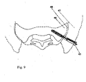
- FIG. 9 shows another application example of a bone screw with a flexible shaft 45 according to FIG. 4 in the region of the band connection between the sacrum 46 and the iliac bone 47 (sacro-iliac joint 48).
- the flexible shaft keeps the natural relative movement obtained between the sacrum and the ilium.
- a gaping of the joint space is reliably prevented by the screw with flexible shaft.
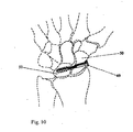
- FIG. 10 shows a further application example of a bone screw with a flexible shaft 49 according to FIG. 4 in the region of the carpal in a band tearing between the navicular bone 50 and the lunar bone 51 (scapholunate dissociation).
- the reduction and stabilization is done by screwing in a screw with a flexible shaft.
- the flexible shaft retains the natural relative movement between the scaphoid and the lunar bone.
- the carpal bones bolted together can not diverge.
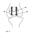
- FIG. 11 shows another example of use of bone screws with flexible shafts 52, 53 in FIG. 1 in a transverse fracture of the patella 54.
- the tensile forces transmitted from the quadriceps tendon via the patella into the patellar tendon are made flexible by the two bone screws Shank transferred and the two fragments of the patella compressed against each other.
- FIG. 12 shows a bone screw according to FIG. 4, in which the wire rope or the wire bundle is reinforced by individual sleeves 55.
- Wire ropes tend according to their winding at initiation of a torsional moment in the opposite direction to wind up.
- By postponing of sleeves or a spiral over the wire rope or wire bundle can limit this winding and at the same time achieve a stabilization of the wire rope by the thereby occurring jamming of the wire rope in the sleeve or the spiral.
- higher torsional moments than with a non-reinforced wire rope or wire bundle can be transmitted.
Description
Die Erfindung betrifft ein Implantat zur augmentierenden Stabilisierung von Knochengelenken mit geringer Relativbewegung und zur interfragmentären Stabilisierung von Knochenbrüchen, wenn vorwiegend Zugkräfte eingeleitet werden sollen.The invention relates to an implant for augmenting stabilization of bone joints with little relative movement and for the interfragmentary stabilization of bone fractures, when primarily tensile forces are to be introduced.
Die Gelenke des Körpers weisen unterschiedliche Bewegungsausmaße auf. Neben den Gelenken in den Hauptbewegungsachsen der Extremitäten sowie dem Kiefergelenk, welche z.T. Relativbewegungen ganz erheblichen Ausmaßes aufweisen, existieren viele Gelenke mit geringem relativen Bewegungsausmaß. Typische Beispiele hierfür sind das Schultereckgelenk als Verbindung zwischen Schulterblatt und Schlüsselbein (Akromioldavikulargelenk), die Gelenkverbindung zwischen Schüsselbein und Brustbein (Sternoklavikulargelenk), das Kreuzdarmbeingelenk (Iliosakralgelenk), die Schambeinfuge (Symphyse), die gelenkigen Verbindungen zwischen Schien- und Wadenbein (proximales und distales Tibiofibulargelenk), die Gelenkverbindungen zwischen den Hand- und Fußwurzelknochen sowie die Gelenkverbindungen zwischen den Knochen der Mittelhand (Metakarpalgelenke) der des Mittelfußes (Metatarsalgelenke). Gleichwohl führen auch Verletzungen dieser Gelenkverbindungen in vielen Fällen zu schwerwiegenden körperlichen Einschränkungen, wobei sich als Folge einer verbleibenden Gelenkinkongruenz eine schmerzhafte Arthrose ausbildet. Therapeutisches Ziel muss daher die exakte Reposition dieser Gelenkverbindungen mit Wiederherstellung des Kapselbandapparates sein. Dies ist in der Regel durch eine einfache Naht des Kapsel-Bandapparates nicht erreichbar. Die Nähte würden der Belastung nicht standhalten, ausreißen und die Gelenkverbindung wieder in eine inkongruente Fehlstellung abgleiten. Vielmehr muss das verletzte Gelenk durch ein geeignetes chirurgisches Implantat im Sinne einer Augmentation solange in einer korrekten Stellung gehalten werden, bis der Kapsel-Bandapparat in ausreichender Festigkeit geheilt ist und die zur Führung der Gelenkverbindung erforderlichen Kräfte wieder übernehmen kann. Gleiches gilt für instabile Knochenbrüche, bei denen nach Reposition der Fraktur ein Implantat den Knochen solange in der korrekten Stellung halten soll, bis die Fraktur in ausreichender Festigkeit verheilt ist.The joints of the body have different degrees of movement. In addition to the joints in the main axes of movement of the extremities and the temporomandibular joint, some of which have relative movements of a considerable extent, there are many joints with a low relative range of motion. Typical examples of this are the shoulder joint as a link between the scapula and collarbone (Akromioldavikulargelenk), the articulation between the calf bone and sternum (sternoclavicular joint), the Kreuzdarmbeingel joint (sacroiliac joint), the pubic symphysis, the articulated connections between the tibia and fibula (proximal and distal Tibiofibular joint), the joints between the bones of the hands and tarsals, and the joints between the bones of the metacarpal joints (metacarpal joints) of the metatarsal (metatarsal) joints. Nevertheless, injuries of these joints also lead to many cases severe physical limitations, with painful arthritis developing as a result of residual joint mismatch. Therapeutic goal must therefore be the exact reduction of these joints with recovery of the capsular ligament apparatus. This is usually not achievable by a simple suture of the capsular ligament apparatus. The seams would not withstand the load, tear out and slide the hinge back into an incongruent misalignment. Rather, the injured joint must be held by a suitable surgical implant in the sense of augmentation in a correct position until the capsular ligament is cured in sufficient strength and can take the necessary forces to guide the joint again. The same applies to unstable fractures in which, after reduction of the fracture, an implant should hold the bone in the correct position until the fracture has healed in sufficient strength.
Zur augmentierenden Stabilisierung von zerrissenen Gelenkverbindungen mit geringen Relativbewegungen sind verschiedene Techniken beschrieben, welche grob in 4 Gruppen unterteilt werden können: 1. temporäre starre Überbrückung der Gelenkverbindung, 2. Überbrückung mit flexiblen Implantaten, 3. Halteimplantate, welche auf einer Gelenkseite verschraubt werden und auf der Gegenseite hakenförmig eingreifen, 4. Implantate mit gelenkiger Verbindung.For augmenting stabilization of torn joints with low relative movements, various techniques are described, which can be roughly divided into 4 groups: 1. temporary rigid bridging of the joint, 2. bridging with flexible implants, 3. retaining implants, which are screwed on a joint side and on engage the opposite side hook-shaped, 4. Implants with articulated connection.
Bekanntester Vertreter der 1. Gruppe (starre Implantate) ist die sogenannte Stellschraube. Bei Anwendung dieses Prinzips werden beide Gelenkpartner durch eine direkte Verschraubung weitestgehend starr gegeneinander fixiert, wodurch zwar die Gelenkkongruenz gewährleistet wird, die Relativbewegung des Gelenkes aber blockiert wird. Ähnliche Funktionen werden durch Überbrückung der Gelenke mit Kirschnerdrähten, ggf. auch ergänzt durch Drahtcerclagen oder durch die Anwendung starrer Osteosyntheseplatten (insbesondere im Bereich des Beckens) erreicht.Well-known representatives of the first group (rigid implants) is the so-called set screw. When applying this principle, both joint partners are fixed by a direct screw largely rigid against each other, whereby although the joint congruence is ensured, but the relative movement of the joint is blocked. Similar functions are achieved by bridging the joints with Kirschner wires, possibly also supplemented by Drahtcerclagen or by the use of rigid osteosynthesis plates (especially in the area of the pelvis).
Bekannte Vertreter der 2. Gruppe (flexible Implantate) sind Kunststoffkordeln oder -Bänder aus resorbierbarem oder nicht resorbierbarem Material (Literatur: Fremerey RW et al (1996) Die operative Behandlung der akuten, kompletten AC-Gelenkssprengung. Unfallchirurg 99:341-5), Drahtseile in der von LABITZKE (Literatur: Labitzke R (1982) Drahtseile und intraossäre Druckverteilungssysteme in der Chirurgie. Chirurg 53:741-3) vorgeschlagenen Technik oder die Anwendung von Drahtcerclagen.Known representatives of the second group (flexible implants) are plastic cords or bands of resorbable or non-resorbable material (literature: Fremerey RW et al (1996) The surgical treatment of acute, complete AC joint blasting accident trauma 99: 341-5), Wire ropes in the technique proposed by LABITZKE (literature: Labitzke R (1982) Wire Rope and Intraosseous Pressure Distribution Systems in Surgery, 53: 741-3) or the use of wire cerclages.
Bekannte Vertreter der 3. Gruppe (verschraubte Implantate mit Haken) sind die von BALSER, WOLTER oder von DREITHALER in ähnlicher Bauweise vorgeschlagenen Hakenplatten zur Stabilisierung von Sprengungen des Schultereckgelenkes oder der von ENGELBRECHT (Literatur: Engelbrecht E et al. (1971) Die Versorgung tibio-fibularer Syndesmosensprengungen mit dem Syndesmosenhaken. Chirurg 42:92) entwickelte Syndesmosenhaken zur Stabilisierung von Sprengungen der Knöchelgabel. Diese Implantate erlauben eine gute Augmentation der Gelenkverbindung und erhalten im wesentlichen die Beweglichkeit, die Einstellung der korrekten Gelenkkongruenz ist jedoch schwierig und kann mitunter nur durch Nachbiegen des Implantates erreicht werden, da diese Implantate keine geeigneten Verstellmöglichkeiten aufweisen. Außerdem ist ein relativ gro-ßer operativer Zugang erforderlich, welcher eine Erweiterung des Operationstraumas bedingt.Well-known representatives of the third group (screw-retained implants with hooks) are the hook plates proposed by BALSER, WOLTER or DREITHALER in a similar construction for the stabilization of bladder loops or ENGELBRECHT (Literature: Engelbrecht E et al (1971) Die Versorgung tibio -fibular syndesmos blasting with the syndesmotic hook, surgeon 42:92) developed syndesmotic hooks to stabilize blasts of the ankle fork. These implants allow a good augmentation of the joint and receive essentially the mobility, the adjustment of the correct Gelenkkongruenz is difficult and can sometimes only be achieved by bending the implant, since these implants have no suitable adjustment options. In addition, a relatively large operational access is required which causes an expansion of the surgical trauma.
Ein typischer Vertreter der 4. Gruppe (Implantate mit integrierter Gelenkverbindung) ist die von RAMANZADEH entwickelte Gelenkplatte zur Stabilisierung von Sprengungen des Schultereckgelenkes. Diese Platte besitzt jedoch den Nachteil, dass die Einstellung einer korrekten Kongruenz des Gelenkes schwierig ist, und dass die Drehachsen des Gelenkes und des Implantates nicht übereinstimmen, wodurch die natürliche Gelenkbewegung zumindest teilweise blockiert wirdA typical representative of the 4th group (implants with integrated joint) is the joint plate developed by RAMANZADEH for the stabilization of bursts of the shoulder joint. However, this plate has the disadvantage that the adjustment of a correct congruence of the joint is difficult, and that the axes of rotation of the joint and the implant do not match, whereby the natural joint movement is at least partially blocked
Die Entgegenhaltung DE 299 15 204 und die Patentschrift US 4,959,064 beschreiben eine Schraube, die im Schaftbereich eine Spiralfeder aufweist. Eine Spiralfeder führt zu einem flexiblen Schraubenschaft, welcher sich unter Zugkraft in Längsrichtung dehnt. Bei der Verwendung einer derartigen Schraube zur Behandlung einer Sprunggelenksgabel mit zerrissenem Syndesmosenband weicht die Knöchelgabel auseinander, woraus eine Verschiebung des Sprungbeins in der Knöchelgabel und damit eine Inkongruenz des oberen Sprunggelenks resultiert. Hierbei droht die Gefahr eines schwerwiegenden Gelenkschadens mit resultierenden Knorpelschäden und der Gefahr einer Arthrose.Document DE 299 15 204 and US Pat. No. 4,959,064 describe a screw which has a helical spring in the shaft region. A spiral spring leads to a flexible screw shaft, which expands under tensile force in the longitudinal direction. When using such a screw to treat an ankle fork with torn Syndesmosenband the ankle fork diverges, resulting in a shift of the ankle bone in the ankle fork and thus an incongruity of the upper ankle joint results. This threatens the risk of serious joint damage with resulting cartilage damage and the risk of osteoarthritis.
Der Erfindung liegt daher die Aufgabe zugrunde, ein Implantat zu entwickeln, welches die Bandverbindungen bei Gelenken mit geringer Relativbewegung zuverlässig augmentiert, dabei aber das natürliche Bewegungsausmaß des Gelenkes nicht oder nicht wesentlich behindert.The invention is therefore based on the object to develop an implant which augments reliably the band joints in joints with little relative movement, but does not or not substantially hinder the natural range of motion of the joint.
Diese Aufgabe wird mit einer implantierbaren Schraube zur Stabilisierung einer Gelenkverbindung oder eines Knochenbruches mit flexiblem Schaft gelöst, bei der die Flexibilität im Schaftbereich durch ein Drahtseil, eine Kordel, ein Drahtbündel oder durch Fäden erzielt wird.This object is achieved with an implantable screw for stabilizing a joint connection or a bone fracture with a flexible shaft, in which the flexibility in the shaft area is achieved by a wire rope, a cord, a wire bundle or by threads.
Diese Bauweise des Implantates gewährleistet fast ausschließlich eine Übertragung von Zugkräften, während Biegemomente, Druck - und Querkräfte durch den flexiblen Schaft nicht bzw. nur unwesentlich übertragen werden.This design of the implant ensures almost exclusively a transmission of tensile forces, while bending moments, pressure and shear forces are transmitted by the flexible shaft not or only slightly.
Ein Drahtseil, eine Kordel, ein Drahtbündel oder Fäden können im Hinblick auf ihre Funktion als Seile bezeichnet werden. Während sich eine Schraube mit Spiralfeder im Schaftbereich unter einer Zugkraft in Längsrichtung dehnt, kommt es bei einem Seil im Schaftbereich auch unter relativ hohen einwirkenden Kräften nicht zu einem Auseinanderweichen der Knöchelgabel. Dagegen lassen sich alle anderen Relativbewegungen (Drehung des Außenknöchels und leichte Translationsbewegungen zwischen Schien- und Wadenbein) ohne relevanten Kraftaufwand ausführen. Durch die Verwendung eines Seiles lässt sich daher die stabilisierende Funktion einer natürlichen Bandverbindung in annährend physiologischer Weise ersetzen. Die Anwendung einer oder mehrerer derartiger Schrauben mit flexiblem Schaft ermöglicht es, die an einer instabilen Gelenkverbindung beteiligten Knochen so miteinander zu verbinden, dass die natürliche Gelenkbewegung nicht oder nur unwesentlich behindert wird.A wire rope, a cord, a wire bundle or threads may be referred to as ropes in terms of their function. While a screw with spiral spring in the shaft area under a tensile force in the longitudinal direction expands, it comes with a rope in the shaft area even under relatively high forces acting not to diverge the ankle fork. In contrast, all other relative movements (rotation of the lateral malleolus and slight translational movements between the tibia and fibula) can be performed without relevant expenditure of force. By using a rope, therefore, the stabilizing function of a natural ligamentous compound can be replaced in an almost physiological manner. The use of one or more such screws with Flexible shaft makes it possible to connect the bones involved in an unstable joint connection together so that the natural joint movement is not or only slightly hampered.
Ebenso wird es durch die Anwendung einer oder mehrerer derartiger Schrauben mit flexiblem Schaft ermöglicht, bei einer Verschraubung von Knochenbrüchen vorwiegend interfragmentäre Zugkräfte einzuleiten.Likewise, by using one or more such flexible shaft screws, it is possible to induce predominantly interfragmental tractive forces when screwing fractures.
Eine derartige Schraube ermöglicht es, dass beide an einer Gelenkverletzung beteiligten Knochen oder an einer Knochenverletzung beteiligten Fragmente durch eine oder mehrere Schrauben verbunden werden, welche einen flexiblen Schaft aufweisen. Diese Bauweise des Implantates gewährleistet fast ausschließlich eine Übertragung von Zugkräften, während Biegemomente, Druck- und Querkräfte durch den flexiblen Schaft nicht bzw. nur unwesentlich übertragen werden. Bei Kapselbandverletzungen eines Gelenkes wird die Schraube bevorzugt so montiert, dass die Schraubenachse mit der Richtung der resultierenden Kraft der Bandverbindung des Gelenkes übereinstimmt. Dabei lässt sich eine ideale Augmentation der Gelenkverbindung erreichen. Bei Knochenbrüchen wird die Schraube senkrecht zur Frakturebene eingebracht und bewirkt durch die Zugkraft eine interfragmentäre Kompression.Such a screw allows both bones involved in joint injury or fragments involved in a bone injury to be connected by one or more screws having a flexible shaft. This design of the implant ensures almost exclusively a transmission of tensile forces, while bending moments, pressure and shear forces are transmitted by the flexible shaft not or only slightly. In capsule ligament injuries of a joint, the screw is preferably mounted so that the screw axis coincides with the direction of the resultant force of the band connection of the joint. In this case, an ideal augmentation of the joint can be achieved. In fractures, the screw is introduced perpendicular to the fracture plane and causes by the tensile force an interfragmentary compression.
Vorteilhafterweise kann durch die Erfindung eine Ausweitung des Operationsraumes begrenzt werden. Die Erfindung ist in vorteilhafter Ausgestaltung zur sogenannten minimal-invasiven Implantation geeignet.Advantageously, an expansion of the operating room can be limited by the invention. The invention is suitable in an advantageous embodiment for so-called minimally invasive implantation.
Darüber hinaus kann die erfindungsgemäße Schraube zur Verwendung in der Chirurgie so gestaltet werden, dass vorwiegend Zugkräfte und keine wesentlichen Biegemomente übertragen werden. Ebenso kann die erfindungsgemäße Schraube so ausgebildet werden, dass diese im Sinne einer sogenannten Kriechschraube in die Markhöhle eines frakturierten Knochens eingebracht werden kann, und sich dabei der meist gebogenen Kontur der Markhöhle anpasst.In addition, the inventive screw for use in surgery can be designed so that mainly tensile forces and no significant bending moments are transmitted. Likewise, the screw according to the invention can be designed so that it can be introduced in the sense of a so-called creeping in the medullary cavity of a fractured bone, and thereby adapts to the most curved contour of the medullary cavity.
Vorteilhaft ist es, wenn das axiale Flächenträgheitsmoment der Schraube um 30%, vorzugsweise mehr als 50% kleiner ist als bei einer Schraube gleichen äußeren Durchmessers.It is advantageous if the axial area moment of inertia of the screw is smaller by 30%, preferably more than 50%, than in the case of a screw of the same outer diameter.
Die Flexibilität wird im Schaftbereich durch ein Drahtseil, ein Drahtbündel, eine Kordel oder durch Fäden erzielt.The flexibility is achieved in the shaft area by a wire rope, a wire bundle, a cord or threads.
Bei Verwendung eines Drahtseiles oder eines Drahtbündels ist es besonders vorteilhaft, wenn das Drahtseil oder das Drahtbündel von außen durch Hülsen oder eine Spirale armiert ist. Bei der Einleitung von Torsionsmomenten wird dadurch ein Aufwickeln des Drahtseiles oder der Drahtbündel begrenzt und hierdurch das Drahtseil bzw. des Drahtbündel stabilisiert. Außerdem lässt sich abhängig von der Größe der Hülsen bzw. der Spiralwindungen und deren Abstand zueinander die Biegebewegung des Schaftes begrenzen.When using a wire rope or a wire bundle, it is particularly advantageous if the wire rope or the wire bundle is reinforced from the outside by sleeves or a spiral. In the initiation of torsional moments thereby winding of the wire rope or the wire bundle is limited, and thereby the wire rope or the wire bundle stabilized. In addition, depending on the size of the sleeves or the spiral turns and their distance from each other limit the bending movement of the shaft.
Besonders vorteilhaft ist es, wenn der Gewindeteil ein Knochengewinde aufweist.It is particularly advantageous if the threaded part has a bone thread.
Ein bevorzugtes Ausführungsbeispiel sieht vor, dass der Kopfteil eine Schraubenschlüsselaufnahme aufweist und je nach Einsatzzweck des Implantates eine glatte Oberfläche oder ein Knochengewinde entsprechend dem Gewindeteil aufweist oder ein Knochengewinde aufweist, welches im Durchmesser größer und in der Gewindesteigung kleiner ist als das Knochengewinde im Gewindeteil.A preferred embodiment provides that the head part has a wrench receptacle and depending on the purpose of the implant has a smooth surface or a bone thread corresponding to the threaded portion or has a bone thread which is larger in diameter and smaller in thread pitch than the bone thread in the threaded portion.
Bei hoher Flexibilität des Schaftes und dadurch bedingter unzureichender Übertragbarkeit der zum Eindringen des Gewindes erforderlichen Torsionsmomente ist es von Vorteil, wenn die implantierbare Schraube Schraubenschlüsselaufnahmen sowohl im Kopfteil als auch im Gewindeteil aufweist. Dies ermöglicht es, einen stufenförmigen Schraubenschlüssel synchron an diesen Schraubenschlüsselaufnahmen angreifen zu lassen.With high flexibility of the shaft and consequent insufficient transferability of the torsion moments required for the penetration of the thread, it is advantageous if the implantable screw has wrench receptacles both in the head part and in the threaded part. This makes it possible to attack a stepped wrench synchronously on these wrench shots.
Weitere vorteilhafte Ausführungsvarianten sind in den Unteransprüchen beschrieben.Further advantageous embodiments are described in the subclaims.
Verschiedene Ausführungsbeispiele der Erfindung sind zeichnerisch dargestellt und werden im folgenden näher beschrieben.Various embodiments of the invention are shown in the drawings and will be described in more detail below.
Es zeigt
- Fig. 1
- eine Knochenschraube, deren Schaft flexibel als Drahtseil oder als Drahtbündel ausgeführt ist,
- Fig. 2
- eine Knochen-Stellschraube, deren Schaft flexibel als Drahtseil oder als Drahtbündel ausgeführt ist,
- Fig. 3
- eine Knochenschraube, die auf der kopffernen Seite ein Knochengewinde aufweist, deren Schaft flexibel als Drahtseil oder als Drahtbündel ausgeführt ist und auf der Kopfseite ein Knochengewinde aufweist, das im Durchmesser größer ist und eine geringere Gewindesteigung aufweist als das kopfferne Knochengewinde,
- Fig. 4
- eine Schraube, die auf der einen Seite ein Knochengewinde aufweist, deren Schaft flexibel als Drahtseil, als Kordel oder als Drahtbündel ausgeführt ist und auf der anderen Seite einen Bolzen mit Metallgewinde und aufgeschraubter Innensechskantkopfmutter aufweist,
- Fig. 5
- einen stufenförmigen Innensechskantschlüssel,
- Fig. 6
- eine Knochenschraube, bei welcher der Schaft aus multiplen Fäden besteht, die jeweils alternierend im Kopfteil und im Gewindeteil der Knochenschraube verankert sind,
- Fig. 7
- ein Anwendungsbeispiel zur Stabilisierung der Knöchelgabel (distales Tibiofibulargelenk, Syndesmose)
- Fig. 8
- ein Anwendungsbeispiel zur Stabilisierung des Schultereckgelenkes (Akromioklavikulargelenk)
- Fig. 9
- ein Anwendungsbeispiel zur Stabilisierung des Kreuzdarmbeingelenkes (Iliosakralfuge),
- Fig. 10
- ein Anwendungsbeispiel zur Stabilisierung im Bereich der Handwurzel bei skapholunärer Dissoziation,
- Fig. 11
- ein Anwendungsbeispiel zur interfragmentären Zugverschraubung im Bereich der Kniescheibe bei einer Patellafraktur und
- Fig. 12
- eine Knochenschraube entsprechend Figur 4, bei der das Drahtseil oder das Drahtbündel durch einzelne Hülsen armiert ist.
- Fig. 1
- a bone screw, the shaft of which is flexibly designed as a wire rope or as a wire bundle,
- Fig. 2
- a bone-adjusting screw, the shaft of which is flexibly designed as a wire rope or as a wire bundle,
- Fig. 3
- a bone screw having a bone thread on the head distant side, the shaft flexible as a wire rope or is designed as a wire bundle and has on the head side a bone thread that is larger in diameter and has a smaller thread pitch than the head distant bone thread,
- Fig. 4
- a screw having on one side a bone thread whose shaft is flexible designed as a wire rope, a cord or a wire bundle and on the other side has a bolt with metal thread and screwed hexagon socket nut,
- Fig. 5
- a stepped Allen key,
- Fig. 6
- a bone screw in which the shaft consists of multiple threads, which are anchored alternately in the head part and in the threaded part of the bone screw,
- Fig. 7
- an application example for the stabilization of the ankle fork (distal tibiofibular joint, syndesmosis)
- Fig. 8
- an application example for the stabilization of the Schultereckgelenkes (Akromioklavikulargelenk)
- Fig. 9
- an application example for the stabilization of the Kreuzdarmbeingelenkenk (iliosacral joint),
- Fig. 10
- an example of application for stabilization in the area of the carpal in scapholunate dissociation,
- Fig. 11
- an application example for the interfragmentary Zugverschraubung in the area of the kneecap in a patellar fracture and
- Fig. 12
- a bone screw according to Figure 4, in which the wire rope or the wire bundle is reinforced by individual sleeves.
Die Fig. 1 zeigt eine Knochenschraube, deren Kopfteil 1 und deren Gewindeteil 2 durch ein Drahtseil oder ein Drahtbündel 3 flexibel miteinander verbunden sind. Das Drahtseil oder das Drahtbündel sind sowohl im Kopfteil, wie im Gewindeteil durch geeignete Verbindungsverfahren (z.B. Press-, Klebe-, Löt- oder Schweißverbindung) fest konnektiert. Die Verwendung eines Drahtseiles oder eines Drahtbündels gestattet die Einleitung von Zugkräften und die Übertragung von Torsionsmomenten im Sinne einer biegsamen Welle. Druckkräfte, Querkräfte oder Biegemomente werden dagegen nur in geringem Maße übertragen.Fig. 1 shows a bone screw, the
Die Fig. 2 zeigt eine Knochen-Stellschraube, die einen mit Knochengewinde versehenen Kopfteil 4 und einen Gewindeteil 5 aufweist, welche analog zu Fig. 1 durch ein Drahtseil oder ein Drahtbündel 6 flexibel miteinander verbunden sind. Dabei sind die Gewinde von Kopfteil und Gewindeteil von gleicher Größe und die Gewindeflanken deckungsgleich. Auf diese Weise wird ein zuvor definierter Abstand zwischen 2 zu verbindenden Knochen unabhängig vom Anzugsmoment der Schraube fixiert.FIG. 2 shows a bone adjusting screw, which has a bone-threaded head part 4 and a threaded
Die Fig. 3 zeigt eine Knochenschraube mit gewindetragendem Kopfteil 7, welcher über ein Drahtseil oder ein Drahtbündel 8 flexibel analog zu Fig. 1 mit dem Gewindeteil 9 verbunden sind. Entsprechend dem bekannten Funktionsprinzip der HERBERT-Schraube weist das Gewinde am Kopfteil gegenüber dem Gewindeteil einen größeren Durchmesser und eine kleinere Gewindesteigung auf. Beim Eindrehen dieser Schraube in einen frakturierten Knochen senkrecht zur Frakturebene werden die beiden Fragmente aufeinander zu bewegt und gegeneinander verspannt, wobei sich das Maß der Zueinanderbewegung pro Schraubenumdrehung aus der Differenz der beiden Gewindesteigungen ergibt.FIG. 3 shows a bone screw with a thread-carrying
Die Fig. 4 zeigt eine Schraube, die auf der einen Seite einen Gewindeteil 10 mit Knochengewinde aufweist, welcher flexibel durch ein Drahtseil, ein Drahtbündel oder eine Kordel 11 mit einem Bolzen 12 verbunden ist, der ein Metall- oder Kunststoffgewinde aufweist. Auf diesen Bolzen ist eine Innensechskantkopfmutter 13 aufgeschraubt. Bei der Implantation einer solchen Schraube wird zunächst der Gewindeteil mit Knochengewinde im Sinne eines Stehbolzens in den Knochen eingeschraubt. Dies geschieht mittels eines kanülierten Steckschlüssels, welcher über das Drahtseil oder das Drahtbündel bzw. die Kordel und den Bolzen geschoben wird und am Außensechskant 14 des Gewindeteils eingreift. Danach wird die Innensechskantkopfmutter mittels eines kanülierten Innensechskantschlüssels auf den Bolzen mit Metallgewinde aufgeschraubt. Abschließend wird das am Innensechskant überstehende Drahtseil oder Drahtbündel bzw. die überstehende Kordel mit einer Kneifzange gekürzt.Fig. 4 shows a screw having on one side a threaded
Die Fig. 5 zeigt einen stufenförmigen Innensechskantschlüssel. Für manche Anwendungen ist es vorteilhaft, wenn der Gewindeteil kanüliert ist so dass die Applikation der Schraube über einen entsprechenden Führungsdraht erfolgen kann.Fig. 5 shows a step-shaped Allen key. For some applications, it is advantageous if the threaded part is cannulated so that the application of the screw can be made via a corresponding guide wire.
Die Fig. 6 zeigt eine Knochenschraube 24, welche sich gleichermaßen für die Fertigung aus Implantatmetall wie aus resorbierbaren oder nicht resorbierbaren Kunststoffen eignet, und welche so gestaltet ist, dass die einzelnen Komponenten gießtechnisch hergestellt werden können. Dabei wird die Flexibilität des Schaftes dadurch erreicht, dass dieser aus multiplen Fäden 25 besteht, welche entweder entsprechend der Abbildung in Ösen 26, 27 alternierend im Kopfteil 28 und im Gewindeteil 29 der Schraube gehalten werden oder jeweils im Kopfteil und im Gewindeteil fest verankert sind.6 shows a
Die Fig. 7 zeigt ein Anwendungsbeispiel einer Knochenschraube mit flexiblem Schaft 32 nach Fig. 4, welche im Bereich der Knöchelgabel zur Augmentation einer zerrissenen Syndesmose 33 (Syndesmose = Bandverbindung zwischen dem Wadenbein 34 und dem Schienbein 35 im Bereich des Sprunggelenkes) eingebracht ist. Im Gegensatz zu einer konventionellen starren Verschraubung bleibt durch den flexiblen Schaft die natürliche Relativbewegung zwischen Wadenbein und Schienbein erhalten. Ein Auseinanderweichen der Knöchelgabel, welches zu einer Instabilität des Sprungbeines 36 führen würde, ist jedoch nicht möglich. Die Dimensionierung der Knochenschraube ist dabei so gewählt, dass sie beim Vorliegen einer begleitenden Außenknöchelfraktur durch die Bohrungen einer üblichen Osteosyntheseplatte in den Knochen eingedreht werden kann.FIG. 7 shows an application example of a bone screw with
Die Fig. 8 zeigt ein weiteres Anwendungsbeispiel einer Knochenschraube mit flexiblem Schaft 37 nach Fig. 1 im Bereich der Bandverbindung zwischen Schulterblatt 38 und Schlüsselbein 39, am Schultereckgelenk 40 (Akromio-Klavikular-Gelenk). Es ist schematisch die Ruptur aller 3 an dieser Verbindung beteiligten Bänder (Lig. acromioclaviculare 41, Lig. trapezoideum 42, Lig. conoideum 43) eingezeichnet. Entsprechend dem 1941 von BOSWORTH für die Verwendung von starren Schrauben beschriebenen Prinzip ist die Schraube mit flexiblem Schaft durch das Schlüsselbein in den Rabenschnabel-Fortsatz 44 eingeschraubt. Im Gegensatz zu einer konventionellen starren Verschraubung bleibt durch den flexiblen Schaft die natürliche Relativbewegung zwischen Schlüsselbein und Schulterblatt erhalten. Ein Hochstand des Schlüsselbeines, welcher zu einer Inkongruenz des Schultereckgelenkes führen würde, ist jedoch nicht möglich.FIG. 8 shows a further example of application of a bone screw with a
Die Fig. 9 zeigt ein weiteres Anwendungsbeispiel einer Knochenschraube mit flexiblem Schaft 45 nach Fig. 4 im Bereich der Bandverbindung zwischen dem Kreuzbein 46 und dem Darmbein 47 (Iliosakralgelenk 48). Bei einer verletzungsbedingten Instabilität des hinteren Beckenringes erfolgt die Stabilisierung durch Eindrehen einer oder mehrerer Schrauben mit flexiblem Schaft. Im Gegensatz zu einer konventionellen starren Verschraubung bleibt durch den flexiblen Schaft die natürliche Relativbewegung zwischen Kreuzbein und Darmbein erhalten. Ein Klaffen des Gelenkspaltes wird durch die Schraube mit flexiblem Schaft jedoch zuverlässig verhindert.FIG. 9 shows another application example of a bone screw with a
Die Fig. 10 zeigt ein weiteres Anwendungsbeispiel einer Knochenschraube mit flexiblem Schaft 49 nach Fig. 4 im Bereich der Handwurzel bei einer Bandzerreißung zwischen dem Kahnbein 50 und dem Mondbein 51 (Skapholunäre Dissoziation). Die Reposition und Stabilisierung erfolgt durch Eindrehen einer Schraube mit flexiblem Schaft. Im Gegensatz zu einer konventionellen starren Verschraubung oder Stabilisierung mit Kirschnerdrähten bleibt durch den flexiblen Schaft die natürliche Relativbewegung zwischen Kahnbein und Mondbein erhalten. Die miteinander verschraubten Handwurzelknochen können jedoch nicht auseinanderweichen.FIG. 10 shows a further application example of a bone screw with a
Die Fig. 11 zeigt ein weiteres Anwendungsbeispiel von Knochenschrauben mit flexiblem Schaft 52, 53 nach Fig. 1 bei einer Querfraktur der Patella 54. Entsprechend dem bekannten Zuggurtungsprinzip werden die von der Quadricepssehne über die Patella in die Patellasehne fortgeleiteten Zugkräfte durch die beiden Knochenschrauben mit flexiblem Schaft übertragen und die beiden Fragmente der Patella gegeneinander komprimiert.FIG. 11 shows another example of use of bone screws with
Die Fig. 12 zeigt eine Knochenschraube gemäß Fig. 4, bei der das Drahtseil oder das Drahtbündel durch einzelne Hülsen 55 armiert ist. Drahtseile neigen entsprechend ihrer Wickelung bei Einleitung eines Torsionsmomentes in Gegenrichtung dazu, sich aufzuwickeln. Durch das Aufschieben von Hülsen oder einer Spirale über das Drahtseil oder Drahtbündel lässt sich dieses Aufwickeln begrenzen und gleichzeitig durch die dabei auftretende Verklemmung des Drahtseiles in der Hülse oder der Spirale eine Stabilisierung des Drahtseiles erreichen. Hierdurch lassen sich höhere Torsionsmomente als mit einem nicht armierten Drahtseil oder Drahtbündel übertragen. Des weiteren lässt sich je nach Gestaltung der Hülsen und je nach Abstand der einzelnen Hülsen bzw. Spiralwindungen zueinander das Ausmaß der Biegung des flexiblen Schraubenschaftes begrenzen.FIG. 12 shows a bone screw according to FIG. 4, in which the wire rope or the wire bundle is reinforced by
Claims (7)
- An implantable screw for stabilising a joint or a bone fracture with a head part (1, 4, 7, 13, 28), a threaded part (2, 5, 9, 10, 29) and a flexible shaft, characterized in that the flexibility in the area of the shaft is achieved through a wire rope (3), a string (11), a bundle of wire (6, 8) or through threads (25).
- The implantable screw according to claim 1, characterized in that the wire rope (3) or the bundle of wire (6, 8) disposed in the area of the shaft is reinforced by a sheath or a coil (55) pulled over from outside.
- The implantable screw according to one of the afore-mentioned claims, characterized in that a threaded part (5, 9, 10) is configured as a stud bolt with a wrench receptacle and has a threaded bolt with a head nut in the area of a head part (4).
- The implantable screw according to claim 3, characterized in that it has wrench receptacle as well in the head part (4) as in the threaded part (5, 9, 10).
- The implantable screw according to one of the afore-mentioned claims, characterized in that a threaded part (5, 9, 10) has a bone thread.
- The implantable screw according to one of the afore-mentioned claims, characterized in that the axial planar moment of inertia of the screw is 30%, preferably 50% smaller than with a screw having the same outer diameter.
- The implantable screw according to one of the afore-mentioned claims, characterized in that as well biocompatible metal as absorbable or non absorbable biocompatible plastic or a combination of such materials are used as a material.
Applications Claiming Priority (2)
| Application Number | Priority Date | Filing Date | Title |
|---|---|---|---|
| DE10129490 | 2001-06-21 | ||
| DE10129490A DE10129490A1 (en) | 2001-06-21 | 2001-06-21 | Implantable screw for stabilization of joint or bone fracture, has flexible shaft which interconnects proximal head portion and distal insertion portion of elongated screw body |
Publications (3)
| Publication Number | Publication Date |
|---|---|
| EP1273269A2 EP1273269A2 (en) | 2003-01-08 |
| EP1273269A3 EP1273269A3 (en) | 2003-12-17 |
| EP1273269B1 true EP1273269B1 (en) | 2007-01-03 |
Family
ID=7688667
Family Applications (1)
| Application Number | Title | Priority Date | Filing Date |
|---|---|---|---|
| EP02007793A Expired - Lifetime EP1273269B1 (en) | 2001-06-21 | 2002-04-06 | Implantable screw for stabilising an articulated joint or a bone fracture |
Country Status (8)
| Country | Link |
|---|---|
| US (2) | US20020198527A1 (en) |
| EP (1) | EP1273269B1 (en) |
| JP (1) | JP4740513B2 (en) |
| AU (1) | AU4888102A (en) |
| CA (1) | CA2391115A1 (en) |
| DE (2) | DE10129490A1 (en) |
| ES (1) | ES2278830T3 (en) |
| ZA (1) | ZA200204327B (en) |
Cited By (3)
| Publication number | Priority date | Publication date | Assignee | Title |
|---|---|---|---|---|
| US8690931B2 (en) | 2007-12-17 | 2014-04-08 | DePuy Synthes Products, LLC | Dynamic bone fixation element and method of using the same |
| US9138219B2 (en) | 2010-12-29 | 2015-09-22 | Tarsus Medical Inc. | Methods and devices for treating a syndesmosis injury |
| CN106618705A (en) * | 2017-01-23 | 2017-05-10 | 南京鼓楼医院 | Flexible connecting vertebral pedicle screw |
Families Citing this family (271)
| Publication number | Priority date | Publication date | Assignee | Title |
|---|---|---|---|---|
| US7938836B2 (en) * | 2003-10-23 | 2011-05-10 | Trans1, Inc. | Driver assembly for simultaneous axial delivery of spinal implants |
| US7601171B2 (en) * | 2003-10-23 | 2009-10-13 | Trans1 Inc. | Spinal motion preservation assemblies |
| US7776068B2 (en) * | 2003-10-23 | 2010-08-17 | Trans1 Inc. | Spinal motion preservation assemblies |
| US7963966B2 (en) * | 2000-06-06 | 2011-06-21 | Cole J Dean | Bone fixation system and method of use |
| US8512376B2 (en) * | 2002-08-30 | 2013-08-20 | Arthrex, Inc. | Method and apparatus for internal fixation of an acromioclavicular joint dislocation of the shoulder |
| US9005245B2 (en) * | 2002-08-30 | 2015-04-14 | Arthrex, Inc. | Acromioclavicular joint fixation technique |
| US8679167B2 (en) * | 2001-10-18 | 2014-03-25 | Orthoip, Llc | System and method for a cap used in the fixation of bone fractures |
| US20100268285A1 (en) * | 2001-10-18 | 2010-10-21 | Orthoip, Llc | Bone screw system and method for the fixation of bone fractures |
| US20090048606A1 (en) * | 2001-10-18 | 2009-02-19 | Fxdevices Llc | Guide system and method for the fixation of bone fractures |
| US20090131936A1 (en) * | 2001-10-18 | 2009-05-21 | Kishore Tipirneni | System and method for the fixation of bone fractures |
| US8702768B2 (en) * | 2001-10-18 | 2014-04-22 | Orthoip, Llc | Cannulated bone screw system and method |
| US8828067B2 (en) | 2001-10-18 | 2014-09-09 | Orthoip, Llc | Bone screw system and method |
| US20080243191A1 (en) * | 2001-10-18 | 2008-10-02 | Fx Devices, Llc | Adjustable bone plate fixation system and metho |
| US20080243132A1 (en) * | 2001-10-18 | 2008-10-02 | Fx Devices, Llc | Tensioning system and method for the fixation of bone fractures |
| US6736819B2 (en) * | 2001-10-18 | 2004-05-18 | Kishore Tipirneni | System and method for fixation of bone fractures |
| US9060809B2 (en) | 2001-10-18 | 2015-06-23 | Orthoip, Llc | Lagwire system and method for the fixation of bone fractures |
| US20090131990A1 (en) * | 2001-10-18 | 2009-05-21 | Kishore Tipirneni | Bone screw system and method |
| US8216243B2 (en) | 2001-12-04 | 2012-07-10 | Synthes Usa, Llc | Headless compression screw with integrated reduction-compression instrument |
| NZ533167A (en) * | 2001-12-04 | 2005-02-25 | Synthes Ag | Bone screw and device for reduction, compression and fixation of bone fragments |
| US7955388B2 (en) * | 2006-11-01 | 2011-06-07 | Acumed Llc | Orthopedic connector system |
| US7776042B2 (en) * | 2002-12-03 | 2010-08-17 | Trans1 Inc. | Methods and apparatus for provision of therapy to adjacent motion segments |
| DE20219683U1 (en) * | 2002-12-19 | 2004-04-29 | Stryker Trauma Gmbh | osteosynthesis |
| DE10305348A1 (en) * | 2003-02-10 | 2004-08-26 | Cell Center Cologne Gmbh | Dynamic epiphyseal telescopic screw |
| AU2003901971A0 (en) * | 2003-04-23 | 2003-05-15 | Dugal Simon Stewart James | A fixation device and method of fixation |
| DE10320417A1 (en) | 2003-05-07 | 2004-12-02 | Biedermann Motech Gmbh | Dynamic anchoring device and dynamic stabilization device for bones, in particular for vertebrae, with such an anchoring device |
| DE10348329B3 (en) | 2003-10-17 | 2005-02-17 | Biedermann Motech Gmbh | Rod-shaped element used in spinal column and accident surgery for connecting two bone-anchoring elements comprises a rigid section and an elastic section that are made in one piece |
| US7967826B2 (en) | 2003-10-21 | 2011-06-28 | Theken Spine, Llc | Connector transfer tool for internal structure stabilization systems |
| US7588575B2 (en) | 2003-10-21 | 2009-09-15 | Innovative Spinal Technologies | Extension for use with stabilization systems for internal structures |
| EP1694228B1 (en) * | 2003-10-23 | 2011-08-31 | TRANS1, Inc. | Spinal mobility preservation apparatus |
| ES2331247T3 (en) | 2003-11-07 | 2009-12-28 | Biedermann Motech Gmbh | SPRING ELEMENT FOR A BONE STABILIZATION DEVICE. |
| US8632570B2 (en) | 2003-11-07 | 2014-01-21 | Biedermann Technologies Gmbh & Co. Kg | Stabilization device for bones comprising a spring element and manufacturing method for said spring element |
| DE10351978A1 (en) * | 2003-11-07 | 2005-06-09 | Biedermann Motech Gmbh | Bone fixing unit e.g. bone screw, for stabilizing device, has shaft provided with elastic sections, and head formed to connect rod with unit that receives axial force due to elastic sections toward shaft axis and bending and torsion forces |
| US7588590B2 (en) | 2003-12-10 | 2009-09-15 | Facet Solutions, Inc | Spinal facet implant with spherical implant apposition surface and bone bed and methods of use |
| US7806914B2 (en) * | 2003-12-31 | 2010-10-05 | Spine Wave, Inc. | Dynamic spinal stabilization system |
| SE528324C2 (en) * | 2004-02-02 | 2006-10-17 | Braanemark Integration Ab | Fixture as well as tooth fixing elements and tooth fasteners |
| US7846183B2 (en) | 2004-02-06 | 2010-12-07 | Spinal Elements, Inc. | Vertebral facet joint prosthesis and method of fixation |
| DE102004010382B4 (en) * | 2004-03-03 | 2006-04-20 | Biedermann Motech Gmbh | Bone anchoring element for anchoring in a bone or in a vertebra and its use in a stabilizing device |
| DE102004010380A1 (en) * | 2004-03-03 | 2005-09-22 | Biedermann Motech Gmbh | Anchoring element and stabilizing device for the dynamic stabilization of vertebrae or bones with such an anchoring element |
| NZ550050A (en) * | 2004-03-26 | 2009-03-31 | Synthes Gmbh | Articulated bone screw |
| US9504583B2 (en) | 2004-06-10 | 2016-11-29 | Spinal Elements, Inc. | Implant and method for facet immobilization |
| US8388667B2 (en) | 2004-08-09 | 2013-03-05 | Si-Bone, Inc. | Systems and methods for the fixation or fusion of bone using compressive implants |
| US20060036251A1 (en) | 2004-08-09 | 2006-02-16 | Reiley Mark A | Systems and methods for the fixation or fusion of bone |
| US8444693B2 (en) | 2004-08-09 | 2013-05-21 | Si-Bone Inc. | Apparatus, systems, and methods for achieving lumbar facet fusion |
| WO2006020531A2 (en) * | 2004-08-09 | 2006-02-23 | Trans1, Inc. | Prosthetic nucleus apparatus and methods |
| US8470004B2 (en) | 2004-08-09 | 2013-06-25 | Si-Bone Inc. | Apparatus, systems, and methods for stabilizing a spondylolisthesis |
| US20180228621A1 (en) | 2004-08-09 | 2018-08-16 | Mark A. Reiley | Apparatus, systems, and methods for the fixation or fusion of bone |
| US8414648B2 (en) | 2004-08-09 | 2013-04-09 | Si-Bone Inc. | Apparatus, systems, and methods for achieving trans-iliac lumbar fusion |
| US20070156241A1 (en) | 2004-08-09 | 2007-07-05 | Reiley Mark A | Systems and methods for the fixation or fusion of bone |
| US9662158B2 (en) | 2004-08-09 | 2017-05-30 | Si-Bone Inc. | Systems and methods for the fixation or fusion of bone at or near a sacroiliac joint |
| US8425570B2 (en) | 2004-08-09 | 2013-04-23 | Si-Bone Inc. | Apparatus, systems, and methods for achieving anterior lumbar interbody fusion |
| US9949843B2 (en) | 2004-08-09 | 2018-04-24 | Si-Bone Inc. | Apparatus, systems, and methods for the fixation or fusion of bone |
| US20120277839A1 (en) | 2004-09-08 | 2012-11-01 | Kramer Jeffery M | Selective stimulation to modulate the sympathetic nervous system |
| JP5132310B2 (en) | 2004-09-08 | 2013-01-30 | スパイナル・モデュレーション・インコーポレイテッド | Neural stimulation method and system |
| US9205261B2 (en) | 2004-09-08 | 2015-12-08 | The Board Of Trustees Of The Leland Stanford Junior University | Neurostimulation methods and systems |
| WO2006034436A2 (en) | 2004-09-21 | 2006-03-30 | Stout Medical Group, L.P. | Expandable support device and method of use |
| EP1814474B1 (en) | 2004-11-24 | 2011-09-14 | Samy Abdou | Devices for inter-vertebral orthopedic device placement |
| US8740955B2 (en) | 2005-02-15 | 2014-06-03 | Zimmer, Inc. | Bone screw with multiple thread profiles for far cortical locking and flexible engagement to a bone |
| US8197523B2 (en) * | 2005-02-15 | 2012-06-12 | Apex Biomedical Company, Llc | Bone screw for positive locking but flexible engagement to a bone |
| WO2006105935A1 (en) * | 2005-04-04 | 2006-10-12 | Zimmer Gmbh | Pedicle screw |
| US20060264954A1 (en) * | 2005-04-07 | 2006-11-23 | Sweeney Thomas M Ii | Active compression screw system and method for using the same |
| US7828828B2 (en) * | 2005-04-14 | 2010-11-09 | Warsaw Orthopedic, Inc | Intervertebral joint |
| US7951198B2 (en) * | 2005-05-10 | 2011-05-31 | Acumed Llc | Bone connector with pivotable joint |
| AU2006202272B2 (en) | 2005-06-02 | 2011-03-31 | Biomet C.V. | Scapholunate disassociation repair system |
| JP5081822B2 (en) | 2005-07-14 | 2012-11-28 | スタウト メディカル グループ,エル.ピー. | Expandable support device and system |
| EP1757243B1 (en) | 2005-08-24 | 2008-05-28 | BIEDERMANN MOTECH GmbH | Rod-shaped implant element for the application in spine surgery or trauma surgery and stabilization device with such a rod-shaped implant element |
| US20070093834A1 (en) * | 2005-10-06 | 2007-04-26 | Stevens Peter M | Bone alignment implant and method of use |
| DE102005053819A1 (en) * | 2005-11-11 | 2007-05-16 | Khd Humboldt Wedag Gmbh | Rotary kiln burner |
| FR2894454B1 (en) * | 2005-12-13 | 2008-08-08 | Maurice Bergoin | ORIGINAL PLATE OF SACRED ATTACHMENT LOCKED BY A S1 SCREWDRIVER SCREW AND AN ILIO-SACRED SCREW USING A VERY ORIGINAL VIEWING DEVICE |
| US9387011B2 (en) * | 2006-02-02 | 2016-07-12 | Steven C. Chudik | Acromioclavicular joint repair system |
| WO2007131002A2 (en) | 2006-05-01 | 2007-11-15 | Stout Medical Group, L.P. | Expandable support device and method of use |
| US8088147B2 (en) * | 2006-10-24 | 2012-01-03 | Trans1 Inc. | Multi-membrane prosthetic nucleus |
| US20100145462A1 (en) * | 2006-10-24 | 2010-06-10 | Trans1 Inc. | Preformed membranes for use in intervertebral disc spaces |
| US20080177333A1 (en) * | 2006-10-24 | 2008-07-24 | Warsaw Orthopedic, Inc. | Adjustable jacking implant |
| EP2099374A4 (en) * | 2006-12-06 | 2012-10-03 | Spinal Modulation Inc | Hard tissue anchors and delivery devices |
| WO2008070807A2 (en) | 2006-12-06 | 2008-06-12 | Spinal Modulation, Inc. | Delivery devices, systems and methods for stimulating nerve tissue on multiple spinal levels |
| US9314618B2 (en) | 2006-12-06 | 2016-04-19 | Spinal Modulation, Inc. | Implantable flexible circuit leads and methods of use |
| WO2008070808A2 (en) | 2006-12-06 | 2008-06-12 | Spinal Modulation, Inc. | Expandable stimulation leads and methods of use |
| US7875058B2 (en) * | 2007-01-17 | 2011-01-25 | Arthrex, Inc. | Bunion repair using suture-button construct |
| US7901431B2 (en) * | 2007-01-17 | 2011-03-08 | Arthrex, Inc. | Lisfranc repair using suture-button construct |
| JP5562648B2 (en) | 2007-01-29 | 2014-07-30 | スパイナル・モデュレーション・インコーポレイテッド | Non-stitched top retaining mechanism |
| US8398690B2 (en) * | 2007-02-07 | 2013-03-19 | Apex Biomedical Company, Llc | Rotationally asymmetric bone screw |
| US8992533B2 (en) | 2007-02-22 | 2015-03-31 | Spinal Elements, Inc. | Vertebral facet joint drill and method of use |
| US8652137B2 (en) | 2007-02-22 | 2014-02-18 | Spinal Elements, Inc. | Vertebral facet joint drill and method of use |
| US8734494B2 (en) * | 2007-04-19 | 2014-05-27 | Stryker Trauma Gmbh | Hip fracture device with static locking mechanism allowing compression |
| US8398636B2 (en) * | 2007-04-19 | 2013-03-19 | Stryker Trauma Gmbh | Hip fracture device with barrel and end cap for load control |
| US8715348B2 (en) * | 2007-04-25 | 2014-05-06 | Alaska Hand Research LLC | Method and device for stabilizing joints with limited axial movement |
| US8043333B2 (en) | 2007-06-08 | 2011-10-25 | Synthes Usa, Llc | Dynamic stabilization system |
| SE533303C2 (en) | 2007-07-24 | 2010-08-17 | Henrik Hansson | Device for fixing bone fragments in case of bone fracture |
| WO2009018527A1 (en) * | 2007-08-02 | 2009-02-05 | Proactive Orthopedic, Llc | Fixation and alignment device and method used in orthopaedic surgery |
| US8882816B2 (en) | 2007-08-02 | 2014-11-11 | Proactive Orthopedics, Llc | Fixation and alignment device and method used in orthopaedic surgery |
| US8551171B2 (en) * | 2007-10-12 | 2013-10-08 | Globus Medical, Inc. | Methods of stabilizing the sacroiliac joint |
| US8066748B2 (en) * | 2007-10-24 | 2011-11-29 | The Cleveland Clinic Foundation | Apparatus and method for affixing body structures |
| US8029478B2 (en) * | 2007-10-31 | 2011-10-04 | Warsaw Orthopedic, Inc. | Implantable device and method for delivering drug depots to a site beneath the skin |
| US8556949B2 (en) | 2007-11-14 | 2013-10-15 | DePuy Synthes Products, LLC | Hybrid bone fixation element and methods of using the same |
| US8808338B2 (en) | 2007-12-05 | 2014-08-19 | Syntorr, Inc. | Flexible bone screw |
| US20090198287A1 (en) | 2008-02-04 | 2009-08-06 | Mark Hsien Nien Chiu | Bone fixation device and method of use thereof |
| WO2009103085A1 (en) * | 2008-02-14 | 2009-08-20 | Arizona Heart Innovative Technologies, Llc | Joint fusion device |
| US8397417B2 (en) | 2008-04-09 | 2013-03-19 | John R. Jamison | Vibration damping in rifle construction |
| US8707605B2 (en) | 2008-04-09 | 2014-04-29 | John R. Jamison | Flexible fasteners for use in rifle construction |
| US9247963B2 (en) * | 2008-08-12 | 2016-02-02 | Charles Kollmer | Bone compression device and methods |
| US9907597B2 (en) | 2008-08-12 | 2018-03-06 | Charles E. Kollmer | Bone compression system and associated methods |
| US8409208B2 (en) * | 2008-10-04 | 2013-04-02 | M. Samy Abdou | Device and method to access the anterior column of the spine |
| EP2373378B1 (en) | 2008-10-27 | 2017-04-26 | Spinal Modulation Inc. | Selective stimulation systems and signal parameters for medical conditions |
| US20100211176A1 (en) | 2008-11-12 | 2010-08-19 | Stout Medical Group, L.P. | Fixation device and method |
| WO2010056895A1 (en) | 2008-11-12 | 2010-05-20 | Stout Medical Group, L.P. | Fixation device and method |
| FR2941859B1 (en) | 2009-02-09 | 2012-04-06 | Memometal Technologies | OSTEOSYNTHESIS SCREW. |
| US8870876B2 (en) | 2009-02-13 | 2014-10-28 | Tarsus Medical Inc. | Methods and devices for treating hallux valgus |
| EP2218415B1 (en) * | 2009-02-16 | 2011-05-04 | Stryker Trauma AG | Bone screw and production method therefor |
| US8303629B1 (en) * | 2009-03-19 | 2012-11-06 | Abdou M Samy | Spinous process fusion and orthopedic implants and methods |
| EP2411091A4 (en) | 2009-03-24 | 2012-09-12 | Spinal Modulation Inc | Pain management with stimulation subthreshold to paresthesia |
| US8015740B2 (en) * | 2009-04-22 | 2011-09-13 | John R. Jamison | Firearm construction employing three point bearing |
| US9204886B2 (en) * | 2009-05-15 | 2015-12-08 | Zimmer, Inc. | Threaded, flexible implant and method for threading a curved hole |
| US9259569B2 (en) * | 2009-05-15 | 2016-02-16 | Daniel M. Brounstein | Methods, systems and devices for neuromodulating spinal anatomy |
| GR1007304B (en) * | 2009-05-27 | 2011-06-08 | Ελευθεριος Σπυριδωνα Νικας | Screw or bolt for the syndesmosis between fibula and tibia |
| JP5460157B2 (en) * | 2009-07-15 | 2014-04-02 | ナカシマメディカル株式会社 | Clavicle fixation plate |
| WO2011025900A1 (en) * | 2009-08-28 | 2011-03-03 | Competitive Global Medical, Llc | Distal interphalangeal fusion device and method of use |
| US8277459B2 (en) | 2009-09-25 | 2012-10-02 | Tarsus Medical Inc. | Methods and devices for treating a structural bone and joint deformity |
| CN101695453B (en) * | 2009-10-26 | 2011-07-13 | 杨惠林 | Vertebral arch pedicle extension device |
| US8377034B2 (en) | 2009-12-04 | 2013-02-19 | Std Med, Inc. | Vascular access port |
| US8764806B2 (en) | 2009-12-07 | 2014-07-01 | Samy Abdou | Devices and methods for minimally invasive spinal stabilization and instrumentation |
| US8357162B2 (en) * | 2010-01-13 | 2013-01-22 | Paul Christopher Frake | Intramedullary mandibular condyle implants and method for application of the same |
| US8652141B2 (en) * | 2010-01-21 | 2014-02-18 | Tarsus Medical Inc. | Methods and devices for treating hallux valgus |
| US8529611B2 (en) | 2010-03-16 | 2013-09-10 | Competitive Global Medical, Llc | Distal interphalangeal fusion method and device |
| JP6231384B2 (en) | 2010-05-10 | 2017-11-15 | スパイナル・モデュレーション・インコーポレイテッドSpinal Modulation Inc. | Method, system and device for suppressing misalignment |
| US8696719B2 (en) | 2010-06-03 | 2014-04-15 | Tarsus Medical Inc. | Methods and devices for treating hallux valgus |
| EP2608747A4 (en) | 2010-08-24 | 2015-02-11 | Flexmedex Llc | Support device and method for use |
| CA2842542C (en) * | 2010-08-29 | 2018-03-27 | Bonfix Ltd. | Orthopedic implant for treatment of bone deformities |
| CA2811130C (en) * | 2010-09-10 | 2015-08-18 | Competitive Global Medical, Llc | Proximal interphalangeal fusion device |
| US9220535B2 (en) | 2010-10-26 | 2015-12-29 | Christian Röbling | Process for introducing a stabilizing element into a vertebral column |
| ES2564415T3 (en) * | 2010-10-26 | 2016-03-22 | Christian Röbling | Device to stabilize a spine |
| EP2455002B1 (en) | 2010-11-17 | 2019-04-03 | Arthrex, Inc. | Adjustable suture-button construct for ankle syndesmosis repair |
| US8685067B2 (en) | 2010-12-21 | 2014-04-01 | Competitive Global Medical, Llc | Compression plate apparatus |
| US10251754B2 (en) * | 2011-01-05 | 2019-04-09 | Peter Forsell | Knee joint device |
| US9168076B2 (en) | 2011-01-25 | 2015-10-27 | Bridging Medical, Llc | Bone compression screw |
| AU2012212150B2 (en) | 2011-02-02 | 2016-09-29 | Spinal Modulation, Inc | Devices, systems and methods for the targeted treatment of movement disorders |
| USD724733S1 (en) | 2011-02-24 | 2015-03-17 | Spinal Elements, Inc. | Interbody bone implant |
| US9271765B2 (en) | 2011-02-24 | 2016-03-01 | Spinal Elements, Inc. | Vertebral facet joint fusion implant and method for fusion |
| US8740949B2 (en) | 2011-02-24 | 2014-06-03 | Spinal Elements, Inc. | Methods and apparatus for stabilizing bone |
| SE535749C2 (en) * | 2011-05-09 | 2012-12-04 | Akoustos Ab | Fixing arrangement with two sub-parts for holding together two constructions and tools for the arrangement |
| WO2013018062A1 (en) * | 2011-08-02 | 2013-02-07 | Nlt Spine Ltd. | Bone screw with deflectable portion |
| US20130041412A1 (en) * | 2011-08-09 | 2013-02-14 | Depuy Spine, Inc. | Flexible pedicle screws |
| US8845728B1 (en) | 2011-09-23 | 2014-09-30 | Samy Abdou | Spinal fixation devices and methods of use |
| USD739935S1 (en) | 2011-10-26 | 2015-09-29 | Spinal Elements, Inc. | Interbody bone implant |
| WO2013071432A1 (en) | 2011-11-14 | 2013-05-23 | The University Of British Columbia | Intramedullary fixation system for management of pelvic and acetabular fractures |
| TWI452993B (en) | 2011-11-17 | 2014-09-21 | Metal Ind Res & Dev Ct | Bone screw, method for manufacturing the bone screw, and tool for mounting and removing the bone screw |
| TWI458461B (en) * | 2011-12-28 | 2014-11-01 | Ind Tech Res Inst | Implant module |
| US9101399B2 (en) | 2011-12-29 | 2015-08-11 | Proactive Orthopedics, Llc | Anchoring systems and methods for surgery |
| US9017404B2 (en) | 2012-01-23 | 2015-04-28 | Lloyd P. Champagne | Devices and methods for tendon repair |
| WO2013120082A1 (en) | 2012-02-10 | 2013-08-15 | Kassab Ghassan S | Methods and uses of biological tissues for various stent and other medical applications |
| US20130226240A1 (en) | 2012-02-22 | 2013-08-29 | Samy Abdou | Spinous process fixation devices and methods of use |
| US9155578B2 (en) * | 2012-02-28 | 2015-10-13 | DePuy Synthes Products, Inc. | Expandable fastener |
| US10363140B2 (en) | 2012-03-09 | 2019-07-30 | Si-Bone Inc. | Systems, device, and methods for joint fusion |
| WO2013134670A1 (en) | 2012-03-09 | 2013-09-12 | Si-Bone Inc. | Integrated implant |
| US8778026B2 (en) | 2012-03-09 | 2014-07-15 | Si-Bone Inc. | Artificial SI joint |
| US9339316B2 (en) | 2012-03-13 | 2016-05-17 | DePuy Synthes Products, Inc. | Dynamic bone fixation element |
| CN104334092A (en) | 2012-05-04 | 2015-02-04 | 西-博恩公司 | Fenestrated implant |
| CN102670291B (en) * | 2012-05-29 | 2014-01-29 | 开平市中心医院 | Inferior tibiofibular bolt elastic fixing device |
| US10179014B1 (en) | 2012-06-01 | 2019-01-15 | Nuvasive, Inc. | Systems and methods for promoting sacroiliac joint fusion |
| EP2872073B1 (en) | 2012-07-12 | 2018-09-19 | Exsomed Holding Company LLC | Metacarpal bone stabilization device |
| DE102012106336A1 (en) * | 2012-07-13 | 2014-01-16 | Aesculap Ag | Bone screw for use in bone fixation system for connecting two bone portions, has distal screw part and proximal screw part, where distal screw part has distal bone thread, and proximal screw part has proximal bone thread |
| US20140031934A1 (en) * | 2012-07-26 | 2014-01-30 | Warsaw Orthopedic, Inc. | Sacro-iliac joint implant system and method |
| US9198767B2 (en) | 2012-08-28 | 2015-12-01 | Samy Abdou | Devices and methods for spinal stabilization and instrumentation |
| US9320617B2 (en) | 2012-10-22 | 2016-04-26 | Cogent Spine, LLC | Devices and methods for spinal stabilization and instrumentation |
| KR101401829B1 (en) | 2012-12-05 | 2014-05-29 | 고려대학교 산학협력단 | Proximal femoral nail with flexible nails apparatus |
| EP2749239B1 (en) * | 2012-12-27 | 2016-12-07 | Biedermann Technologies GmbH & Co. KG | Dynamic bone anchor |
| EP2953580A2 (en) | 2013-02-11 | 2015-12-16 | Cook Medical Technologies LLC | Expandable support frame and medical device |
| US9724149B2 (en) | 2013-03-07 | 2017-08-08 | Warsaw Orhtopedic, Inc. | Surgical implant system and method |
| USD765853S1 (en) | 2013-03-14 | 2016-09-06 | Spinal Elements, Inc. | Flexible elongate member with a portion configured to receive a bone anchor |
| US9421044B2 (en) | 2013-03-14 | 2016-08-23 | Spinal Elements, Inc. | Apparatus for bone stabilization and distraction and methods of use |
| US9820784B2 (en) | 2013-03-14 | 2017-11-21 | Spinal Elements, Inc. | Apparatus for spinal fixation and methods of use |
| US9936983B2 (en) | 2013-03-15 | 2018-04-10 | Si-Bone Inc. | Implants for spinal fixation or fusion |
| GB2530960A (en) | 2013-07-03 | 2016-04-06 | Acute Innovations Llc | Steerable fastener for bone |
| US9839450B2 (en) | 2013-09-27 | 2017-12-12 | Spinal Elements, Inc. | Device and method for reinforcement of a facet |
| US9456855B2 (en) | 2013-09-27 | 2016-10-04 | Spinal Elements, Inc. | Method of placing an implant between bone portions |
| US11259849B2 (en) | 2013-10-02 | 2022-03-01 | ExsoMed Corporation | Full wrist fusion device |
| CN103479417B (en) * | 2013-10-14 | 2015-08-26 | 天津正天医疗器械有限公司 | Inferior tibiofibular joint hinge type flexible retainer |
| US11147688B2 (en) | 2013-10-15 | 2021-10-19 | Si-Bone Inc. | Implant placement |
| US9839448B2 (en) | 2013-10-15 | 2017-12-12 | Si-Bone Inc. | Implant placement |
| WO2015070257A1 (en) | 2013-11-11 | 2015-05-14 | Mẍ Orthopedics, Corp. | Screws for generating and applying compression within a body |
| RU2551303C1 (en) * | 2013-11-13 | 2015-05-20 | Государственное автономное учреждение здравоохранения "Республиканская клиническая больница Министерства здравоохранения Республики Татарстан" | Method of treating compound pronation-eversional fractures of distal knee joint |
| WO2015073642A1 (en) | 2013-11-13 | 2015-05-21 | Mx Orthopedics, Corp. | Staples for generating and applying compression within a body |
| CN104665906B (en) * | 2013-11-26 | 2017-09-08 | 财团法人工业技术研究院 | Bionic fixing device |
| CN104665913B (en) | 2013-11-26 | 2017-06-06 | 财团法人工业技术研究院 | Bionic fixing device and pulling-out device thereof |
| US10085779B2 (en) * | 2013-12-17 | 2018-10-02 | Stichting Katholieke Universiteit | Intramedullary device for mid-shaft clavicle fractures |
| US9622523B2 (en) | 2014-01-06 | 2017-04-18 | Exsomed International IP, LLC | Ergonomic work gloves |
| WO2015134750A1 (en) | 2014-03-06 | 2015-09-11 | University Of British Columbia | Shape adaptable intramedullary fixation device |
| WO2015153976A1 (en) | 2014-04-03 | 2015-10-08 | Versago Vascular Access, Inc. | Devices and methods for installation and removal of a needle tip of a needle |
| US10064670B2 (en) * | 2014-05-12 | 2018-09-04 | DePuy Synthes Products, Inc. | Sacral fixation system |
| JP6640115B2 (en) * | 2014-05-12 | 2020-02-05 | デピュイ・シンセス・プロダクツ・インコーポレイテッド | Sacral fixation system |
| US10045803B2 (en) * | 2014-07-03 | 2018-08-14 | Mayo Foundation For Medical Education And Research | Sacroiliac joint fusion screw and method |
| US9764122B2 (en) | 2014-07-25 | 2017-09-19 | Warsaw Orthopedic, Inc. | Drug delivery device and methods having an occluding member |
| US9775978B2 (en) | 2014-07-25 | 2017-10-03 | Warsaw Orthopedic, Inc. | Drug delivery device and methods having a retaining member |
| EP3003184A4 (en) * | 2014-08-11 | 2016-09-28 | Wright Medical Tech Inc | Flexible screw and methods for syndesmosis repair |
| US11478275B2 (en) | 2014-09-17 | 2022-10-25 | Spinal Elements, Inc. | Flexible fastening band connector |
| US10166033B2 (en) | 2014-09-18 | 2019-01-01 | Si-Bone Inc. | Implants for bone fixation or fusion |
| JP6542362B2 (en) | 2014-09-18 | 2019-07-10 | エスアイ−ボーン・インコーポレイテッドSi−Bone, Inc. | Matrix implant |
| EP3206608B1 (en) | 2014-10-14 | 2023-07-05 | The University of British Columbia | Systems for intramedullary bone fixation |
| DE102014116776A1 (en) * | 2014-11-17 | 2016-05-19 | Aesculap Ag | Bone screw and bone fixation system |
| WO2016081528A1 (en) | 2014-11-17 | 2016-05-26 | Bridging Medical, Llc | Bone compression systems |
| CN106999219B (en) | 2014-12-15 | 2021-04-27 | 史密夫和内修有限公司 | Active fracture compression implant and method |
| DE102014226493B4 (en) * | 2014-12-18 | 2020-11-12 | Holger Erne | Connecting element for fixing at least two bones or bone fragments of a living being |
| JP6673919B2 (en) | 2014-12-18 | 2020-03-25 | ヴェルサゴ ヴァスキュラー アクセス インコーポレイテッド | Devices, systems, and methods for removal and replacement of catheters for implantable access ports |
| CA2971215A1 (en) | 2014-12-18 | 2016-06-23 | Versago Vascular Access, Inc. | Catheter patency systems and methods |
| JP2018502693A (en) | 2015-01-27 | 2018-02-01 | スパイナル・エレメンツ・インコーポレーテッド | Facet joint implant |
| JP2018503458A (en) | 2015-01-28 | 2018-02-08 | アースレックス インコーポレイテッド | Self-compression screw for creating and applying compression in the body |
| WO2016133938A1 (en) | 2015-02-16 | 2016-08-25 | Akros Medical, Inc. | Devices, systems, and methods for semi-rigid bone fixation |
| WO2016154417A1 (en) | 2015-03-24 | 2016-09-29 | Mẍ Orthopedics, Corp. | Staples for generating and applying compression within a body |
| US10376206B2 (en) | 2015-04-01 | 2019-08-13 | Si-Bone Inc. | Neuromonitoring systems and methods for bone fixation or fusion procedures |
| WO2016186847A1 (en) | 2015-05-19 | 2016-11-24 | Exsomed International IP, LLC | Distal radius plate |
| US10376367B2 (en) | 2015-07-02 | 2019-08-13 | First Ray, LLC | Orthopedic fasteners, instruments and methods |
| US10154863B2 (en) | 2015-07-13 | 2018-12-18 | IntraFuse, LLC | Flexible bone screw |
| US10485595B2 (en) | 2015-07-13 | 2019-11-26 | IntraFuse, LLC | Flexible bone screw |
| US10499960B2 (en) | 2015-07-13 | 2019-12-10 | IntraFuse, LLC | Method of bone fixation |
| US10136929B2 (en) | 2015-07-13 | 2018-11-27 | IntraFuse, LLC | Flexible bone implant |
| WO2017011652A1 (en) | 2015-07-14 | 2017-01-19 | Versago Vascular Access, Inc. | Medical access ports, transfer devices and methods of use thereof |
| US10857003B1 (en) | 2015-10-14 | 2020-12-08 | Samy Abdou | Devices and methods for vertebral stabilization |
| AU2016247221B2 (en) | 2015-10-23 | 2021-03-11 | K2M, Inc. | Semi-constrained bone screw and insertion instrument |
| US10357260B2 (en) | 2015-11-02 | 2019-07-23 | First Ray, LLC | Orthopedic fastener, retainer, and guide methods |
| US10076650B2 (en) | 2015-11-23 | 2018-09-18 | Warsaw Orthopedic, Inc. | Enhanced stylet for drug depot injector |
| TWI587847B (en) | 2015-12-07 | 2017-06-21 | 財團法人工業技術研究院 | Implant device for osseous integration |
| US10245091B2 (en) | 2015-12-30 | 2019-04-02 | Exsomed Holding Company, Llc | Dip fusion spike screw |
| US11147604B2 (en) | 2016-01-12 | 2021-10-19 | ExsoMed Corporation | Bone stabilization device |
| CN105496531B (en) * | 2016-02-04 | 2017-11-28 | 宝楠生技股份有限公司 | Fibula is fixed on the fixing device of shin bone again after blocking |
| US11224467B2 (en) | 2016-02-26 | 2022-01-18 | Activortho, Inc. | Active compression apparatus, methods of assembly and methods of use |
| IL261289B2 (en) | 2016-02-26 | 2023-04-01 | Activortho Inc | Active compression apparatus, methods of assembly and methods of use |
| US10214359B2 (en) | 2016-02-29 | 2019-02-26 | Fenner U.S., Inc. | Conveyor belt connector and method for forming a belt |
| US10413332B2 (en) | 2016-04-25 | 2019-09-17 | Imds Llc | Joint fusion implant and methods |
| US9833321B2 (en) | 2016-04-25 | 2017-12-05 | Imds Llc | Joint fusion instrumentation and methods |
| US10194923B2 (en) | 2016-05-10 | 2019-02-05 | Exsomed International IP, LLC | Tool for percutaneous joint cartilage destruction and preparation for joint fusion |
| US11013506B2 (en) | 2017-11-01 | 2021-05-25 | Wright Medical Technology, Inc. | Partially assembled knotless suture construct |
| USD802755S1 (en) | 2016-06-23 | 2017-11-14 | Warsaw Orthopedic, Inc. | Drug pellet cartridge |
| CN109862840B (en) | 2016-10-05 | 2023-10-27 | 不列颠哥伦比亚大学 | Intramedullary fixation device with form-locking interface |
| DE102016011947A1 (en) | 2016-10-05 | 2018-04-05 | Bluewater Medical GmbH | Screw with a head part, a threaded part and a connecting part |
| US10744000B1 (en) | 2016-10-25 | 2020-08-18 | Samy Abdou | Devices and methods for vertebral bone realignment |
| US10973648B1 (en) | 2016-10-25 | 2021-04-13 | Samy Abdou | Devices and methods for vertebral bone realignment |
| US10667923B2 (en) | 2016-10-31 | 2020-06-02 | Warsaw Orthopedic, Inc. | Sacro-iliac joint implant system and method |
| US10434261B2 (en) | 2016-11-08 | 2019-10-08 | Warsaw Orthopedic, Inc. | Drug pellet delivery system and method |
| US10413344B2 (en) * | 2017-02-07 | 2019-09-17 | Simfix Surgical Inc. | Devices and methods for repairing bone fractures |
| US11051799B2 (en) | 2017-09-01 | 2021-07-06 | Wright Medical Technology, Inc. | Augmented suture construct for syndesmotic stabilization |
| AU2018328102C1 (en) | 2017-09-05 | 2023-08-03 | ExsoMed Corporation | Intramedullary threaded nail for radial cortical fixation |
| US11147681B2 (en) | 2017-09-05 | 2021-10-19 | ExsoMed Corporation | Small bone angled compression screw |
| US11191645B2 (en) | 2017-09-05 | 2021-12-07 | ExsoMed Corporation | Small bone tapered compression screw |
| US11179234B2 (en) | 2017-09-15 | 2021-11-23 | Paragon 28, Inc. | Ligament fixation system, implants, devices, and methods of use |
| WO2019055923A1 (en) * | 2017-09-15 | 2019-03-21 | Paragon 28, Inc. | Ligament fixation system, implants, devices, and methods of use |
| WO2019067584A1 (en) | 2017-09-26 | 2019-04-04 | Si-Bone Inc. | Systems and methods for decorticating the sacroiliac joint |
| WO2019071273A1 (en) * | 2017-10-06 | 2019-04-11 | Paragon 28, Inc. | Ligament fixation system, implants, devices, and methods of use |
| ES2955370T3 (en) | 2017-10-25 | 2023-11-30 | Paragon 28 Inc | Fixation system for ligaments, implants and devices with compression cap |
| EP3720376A4 (en) * | 2017-12-04 | 2021-08-04 | Activortho, Inc. | Active compression apparatus, methods of assembly and methods of use |
| US10888363B2 (en) | 2017-12-06 | 2021-01-12 | Stout Medical Group, L.P. | Attachment device and method for use |
| WO2019126306A1 (en) | 2017-12-21 | 2019-06-27 | Versago Vascular Access, Inc. | Medical access ports, transfer devices and methods of use thereof |
| RU2690613C1 (en) * | 2018-02-01 | 2019-06-04 | Ахметкали Зайнолдаевич Дюсупов | Device for elimination of foot subluxation, diastasis of tibia syndesmosis, displacement of ankle fragments and transarticular fixation of foot to tibia |
| WO2019168817A1 (en) * | 2018-02-27 | 2019-09-06 | The University Of Toledo | Syndesmosis fixation and reconstruction system and method of using the same |
| US11179248B2 (en) | 2018-10-02 | 2021-11-23 | Samy Abdou | Devices and methods for spinal implantation |
| US11832856B2 (en) | 2018-10-17 | 2023-12-05 | The University Of British Columbia | Bone-fixation device and system |
| AU2019377125A1 (en) * | 2018-11-08 | 2021-05-27 | Nextremity Solutions, Inc. | Bone fixation device and method |
| WO2020168269A1 (en) | 2019-02-14 | 2020-08-20 | Si-Bone Inc. | Implants for spinal fixation and or fusion |
| US11369419B2 (en) | 2019-02-14 | 2022-06-28 | Si-Bone Inc. | Implants for spinal fixation and or fusion |
| JP2022535698A (en) | 2019-05-22 | 2022-08-10 | スパイナル・エレメンツ・インコーポレーテッド | Bone ties and bone tie inserters |
| US11457959B2 (en) | 2019-05-22 | 2022-10-04 | Spinal Elements, Inc. | Bone tie and bone tie inserter |
| WO2021011313A1 (en) * | 2019-07-12 | 2021-01-21 | Stout Medical Group, L.P. | Attachment device and method for use |
| US11564812B2 (en) | 2019-09-09 | 2023-01-31 | Warsaw Orthopedic, Inc. | Surgical instrument and method |
| US11344354B2 (en) | 2019-09-09 | 2022-05-31 | Warsaw Orthopedic, Inc. | Surgical instrument and method |
| US11672570B2 (en) | 2019-11-27 | 2023-06-13 | Si-Bone Inc. | Bone stabilizing implants and methods of placement across SI Joints |
| WO2021163313A1 (en) | 2020-02-14 | 2021-08-19 | Spinal Elements, Inc. | Bone tie methods |
| WO2022125619A1 (en) | 2020-12-09 | 2022-06-16 | Si-Bone Inc. | Sacro-iliac joint stabilizing implants and methods of implantation |
| US11737883B2 (en) | 2021-03-02 | 2023-08-29 | Arthrex, Inc. | Orthopaedic implants including breakaway fastener |
| US20220354557A1 (en) * | 2021-05-10 | 2022-11-10 | Trilliant Surgical Llc | Semi-rigid device for orthopedic fixation |
| US11553948B2 (en) | 2021-05-20 | 2023-01-17 | University Of Utah Research Foundation | Bone fixation devices, systems, and methods |
| DE102021118087A1 (en) | 2021-07-13 | 2023-01-19 | Ot Medizintechnik Gmbh | Symphysis Plate and Set |
| US11317956B1 (en) * | 2021-08-26 | 2022-05-03 | University Of Utah Research Foundation | Active compression bone screw |
| WO2023212615A2 (en) * | 2022-04-26 | 2023-11-02 | Rensselaer Polytechnic Institute | Implantable screw and methods for use |
Family Cites Families (19)
| Publication number | Priority date | Publication date | Assignee | Title |
|---|---|---|---|---|
| US4959064A (en) * | 1988-10-07 | 1990-09-25 | Boehringer Mannheim Corporation | Dynamic tension bone screw |
| US4947502A (en) * | 1988-10-07 | 1990-08-14 | Boehringer Mannheim Corporation | Method of making a dynamic tension bone screw |
| CH681273A5 (en) * | 1988-12-16 | 1993-02-26 | Sulzer Ag | |
| US5152790A (en) * | 1991-03-21 | 1992-10-06 | American Cyanamid Company | Ligament reconstruction graft anchor apparatus |
| US5061137A (en) * | 1991-04-29 | 1991-10-29 | Ford Motor Company | Fastener with resilient linking means |
| US5518351A (en) * | 1991-11-18 | 1996-05-21 | Peil; Eugene D. | Self-tapping screw having threaded nut as a head |
| SE510158C2 (en) * | 1992-10-29 | 1999-04-26 | Medevelop Ab | Anchorage elements for supporting prostheses and the use of such anchorage elements for fixing dentures |
| US5411523A (en) * | 1994-04-11 | 1995-05-02 | Mitek Surgical Products, Inc. | Suture anchor and driver combination |
| US5571139A (en) * | 1995-05-19 | 1996-11-05 | Jenkins, Jr.; Joseph R. | Bidirectional suture anchor |
| US5584629A (en) * | 1995-05-30 | 1996-12-17 | Crystal Medical Technology, A Division Of Folsom Metal Products, Inc. | Connector for medical implant |
| NL1005394C1 (en) * | 1996-04-01 | 1997-10-02 | Kokbing Lo | Fixing element and strap fixed with fixing element. |
| US6436124B1 (en) * | 1996-12-19 | 2002-08-20 | Bionx Implants Oy | Suture anchor |
| US5814047A (en) * | 1997-03-04 | 1998-09-29 | Industrial Technology Research Institute | Intramedullary nail fixation apparatus and its fixation method |
| US6010507A (en) * | 1998-07-24 | 2000-01-04 | Rudloff; David A. C. | Repair of bone fracture using flexible fully or partially cannulated compression/decompression fixation element |
| US6368326B1 (en) * | 1998-09-28 | 2002-04-09 | Daos Limited | Internal cord fixation device |
| FR2784019B3 (en) * | 1998-10-05 | 2000-08-04 | Jean Louis Audren | LOCKABLE ELASTIC CENTRO-MEDULAR NAIL FOR OSTEOSYNTHESIS OF HUMERUS FRACTURES |
| DE29915204U1 (en) * | 1999-08-26 | 1999-12-09 | Hoffmann Olaf | Spring screw |
| DE60128082D1 (en) * | 2000-05-24 | 2007-06-06 | Joseph H Sklar | COMPRESSED TENANT RANSPLANT AND MACHINE FOR MANUFACTURING |
| US6908275B2 (en) * | 2002-04-29 | 2005-06-21 | Charles Nelson | Fastener having supplemental support and retention capabilities |
-
2001
- 2001-06-21 DE DE10129490A patent/DE10129490A1/en not_active Withdrawn
-
2002
- 2002-04-06 ES ES02007793T patent/ES2278830T3/en not_active Expired - Lifetime
- 2002-04-06 EP EP02007793A patent/EP1273269B1/en not_active Expired - Lifetime
- 2002-04-06 DE DE50209129T patent/DE50209129D1/en not_active Expired - Lifetime
- 2002-05-10 JP JP2002134818A patent/JP4740513B2/en not_active Expired - Fee Related
- 2002-05-30 ZA ZA200204327A patent/ZA200204327B/en unknown
- 2002-06-18 US US10/174,906 patent/US20020198527A1/en not_active Abandoned
- 2002-06-20 AU AU48881/02A patent/AU4888102A/en not_active Abandoned
- 2002-06-21 CA CA002391115A patent/CA2391115A1/en not_active Abandoned
-
2005
- 2005-04-07 US US11/100,844 patent/US7625395B2/en active Active
Cited By (5)
| Publication number | Priority date | Publication date | Assignee | Title |
|---|---|---|---|---|
| US8690931B2 (en) | 2007-12-17 | 2014-04-08 | DePuy Synthes Products, LLC | Dynamic bone fixation element and method of using the same |
| US9414875B2 (en) | 2007-12-17 | 2016-08-16 | DePuy Synthes Products, Inc. | Dynamic bone fixation element and method of using the same |
| US9138219B2 (en) | 2010-12-29 | 2015-09-22 | Tarsus Medical Inc. | Methods and devices for treating a syndesmosis injury |
| CN106618705A (en) * | 2017-01-23 | 2017-05-10 | 南京鼓楼医院 | Flexible connecting vertebral pedicle screw |
| CN106618705B (en) * | 2017-01-23 | 2018-09-21 | 南京鼓楼医院 | A kind of flexible connection pedicle screw |
Also Published As
| Publication number | Publication date |
|---|---|
| EP1273269A3 (en) | 2003-12-17 |
| ES2278830T3 (en) | 2007-08-16 |
| JP4740513B2 (en) | 2011-08-03 |
| ZA200204327B (en) | 2002-10-24 |
| EP1273269A2 (en) | 2003-01-08 |
| US20050177167A1 (en) | 2005-08-11 |
| US20020198527A1 (en) | 2002-12-26 |
| DE50209129D1 (en) | 2007-02-15 |
| CA2391115A1 (en) | 2002-12-21 |
| AU4888102A (en) | 2003-01-02 |
| JP2003010199A (en) | 2003-01-14 |
| US7625395B2 (en) | 2009-12-01 |
| DE10129490A1 (en) | 2003-01-02 |
Similar Documents
| Publication | Publication Date | Title |
|---|---|---|
| EP1273269B1 (en) | Implantable screw for stabilising an articulated joint or a bone fracture | |
| Seitz et al. | Repair of the tibiofibular syndesmosis with a flexible implant | |
| US7410489B2 (en) | Internal cord fixation device | |
| EP1691701B1 (en) | Set of osteosynthesis plates | |
| EP1024762B1 (en) | Bone fixation device | |
| EP2328518B1 (en) | Knee arthrodesis implant | |
| AT507086B1 (en) | IMPLANT, IN PARTICULAR BRAND NAIL FOR THE TREATMENT OF A PROXIMAL HUMERUS FRACTURE | |
| US9517097B2 (en) | Low-profile, high tension mesh plate for subcutaneous fracture fixation | |
| EP0999797B1 (en) | Intramedullary osteosynthesis nail for healing fractures or bone elongation | |
| EP2053980A1 (en) | Trochanter retention plate | |
| EP0645985B1 (en) | Plate-screw implant | |
| EP0217317A2 (en) | Implant for the neck of the femur | |
| EP1927322B1 (en) | Device for positioning tubular bones | |
| DE602004006774T2 (en) | FIXATOR FOR THE REPAIR OF TUBE BONE FRACTURES | |
| WO2010054493A1 (en) | Intramedullary apparatus for arthrodesis or osteosynthesis | |
| EP2696783B1 (en) | Surgical implant for widening a vertebral canal | |
| EP0844855A1 (en) | Endoprosthesis, in particular an artificial hip joint | |
| DE19743048A1 (en) | Bone fracture treatment device | |
| Richter | Posterior Instrumentation of the Cervical Spine for Instability Using the “neon occipito-cervical system” Part 1: Atlanto-Axial Instrumentation: Teil 1: Atlantoaxiale Instrumentierung | |
| Slongo | Osteotomien am proximalen Femur bei Kindern | |
| DE212021000375U1 (en) | Bone fixation system and elements thereof | |
| DE112021002331T5 (en) | Improved linear fibula nail | |
| Christensen | Shortening in pseudarthrosis. Treatment with the Küntscher distractor | |
| Steinböck | The horizontally directed “V” displacement osteotomy of the metatarsal head according to Austin for the treatment of hallux valgus | |
| WO2012041815A1 (en) | Bone screw for use in osteosynthesis |
Legal Events
| Date | Code | Title | Description |
|---|---|---|---|
| PUAI | Public reference made under article 153(3) epc to a published international application that has entered the european phase |
Free format text: ORIGINAL CODE: 0009012 |
|
| AK | Designated contracting states |
Kind code of ref document: A2 Designated state(s): AT BE CH CY DE DK ES FI FR GB GR IE IT LI LU MC NL PT SE TR |
|
| AX | Request for extension of the european patent |
Free format text: AL;LT;LV;MK;RO;SI |
|
| PUAL | Search report despatched |
Free format text: ORIGINAL CODE: 0009013 |
|
| AK | Designated contracting states |
Kind code of ref document: A3 Designated state(s): AT BE CH CY DE DK ES FI FR GB GR IE IT LI LU MC NL PT SE TR |
|
| AX | Request for extension of the european patent |
Extension state: AL LT LV MK RO SI |
|
| RIC1 | Information provided on ipc code assigned before grant |
Ipc: 7A 61B 17/70 A Ipc: 7A 61B 17/72 B Ipc: 7A 61B 17/86 B |
|
| 17P | Request for examination filed |
Effective date: 20040616 |
|
| AKX | Designation fees paid |
Designated state(s): CH DE ES FR GB LI |
|
| GRAP | Despatch of communication of intention to grant a patent |
Free format text: ORIGINAL CODE: EPIDOSNIGR1 |
|
| GRAS | Grant fee paid |
Free format text: ORIGINAL CODE: EPIDOSNIGR3 |
|
| GRAA | (expected) grant |
Free format text: ORIGINAL CODE: 0009210 |
|
| AK | Designated contracting states |
Kind code of ref document: B1 Designated state(s): CH DE ES FR GB LI |
|
| REG | Reference to a national code |
Ref country code: GB Ref legal event code: FG4D Free format text: NOT ENGLISH |
|
| REF | Corresponds to: |
Ref document number: 50209129 Country of ref document: DE Date of ref document: 20070215 Kind code of ref document: P |
|
| REG | Reference to a national code |
Ref country code: CH Ref legal event code: NV Representative=s name: E. BLUM & CO. AG PATENT- UND MARKENANWAELTE VSP |
|
| ET | Fr: translation filed | ||
| REG | Reference to a national code |
Ref country code: ES Ref legal event code: FG2A Ref document number: 2278830 Country of ref document: ES Kind code of ref document: T3 |
|
| PLBE | No opposition filed within time limit |
Free format text: ORIGINAL CODE: 0009261 |
|
| STAA | Information on the status of an ep patent application or granted ep patent |
Free format text: STATUS: NO OPPOSITION FILED WITHIN TIME LIMIT |
|
| 26N | No opposition filed |
Effective date: 20071005 |
|
| REG | Reference to a national code |
Ref country code: CH Ref legal event code: PUE Owner name: NOVOPLANT GMBH Free format text: HILDINGER, KARL HEINZ#KLEINHEIDSTRASSE 1A#52080 AACHEN (DE) $ MUECKTER, HELMUT, DR. MED. DIPL.-ING.#EUPENER STRASSE 291#52076 AACHEN (DE) -TRANSFER TO- NOVOPLANT GMBH#REITMORSTRASSE 51#80538 MUENCHEN (DE) |
|
| REG | Reference to a national code |
Ref country code: GB Ref legal event code: 732E |
|
| REG | Reference to a national code |
Ref country code: ES Ref legal event code: PC2A |
|
| REG | Reference to a national code |
Ref country code: FR Ref legal event code: TP |
|
| REG | Reference to a national code |
Ref country code: FR Ref legal event code: PLFP Year of fee payment: 14 |
|
| PGFP | Annual fee paid to national office [announced via postgrant information from national office to epo] |
Ref country code: CH Payment date: 20150521 Year of fee payment: 14 Ref country code: ES Payment date: 20150527 Year of fee payment: 14 |
|
| PGFP | Annual fee paid to national office [announced via postgrant information from national office to epo] |
Ref country code: FR Payment date: 20150429 Year of fee payment: 14 |
|
| REG | Reference to a national code |
Ref country code: CH Ref legal event code: PL |
|
| REG | Reference to a national code |
Ref country code: FR Ref legal event code: ST Effective date: 20161230 |
|
| PG25 | Lapsed in a contracting state [announced via postgrant information from national office to epo] |
Ref country code: CH Free format text: LAPSE BECAUSE OF NON-PAYMENT OF DUE FEES Effective date: 20160430 Ref country code: FR Free format text: LAPSE BECAUSE OF NON-PAYMENT OF DUE FEES Effective date: 20160502 Ref country code: LI Free format text: LAPSE BECAUSE OF NON-PAYMENT OF DUE FEES Effective date: 20160430 |
|
| PG25 | Lapsed in a contracting state [announced via postgrant information from national office to epo] |
Ref country code: ES Free format text: LAPSE BECAUSE OF NON-PAYMENT OF DUE FEES Effective date: 20160407 |
|
| REG | Reference to a national code |
Ref country code: ES Ref legal event code: FD2A Effective date: 20181204 |
|
| PGFP | Annual fee paid to national office [announced via postgrant information from national office to epo] |
Ref country code: DE Payment date: 20200424 Year of fee payment: 19 |
|
| PGFP | Annual fee paid to national office [announced via postgrant information from national office to epo] |
Ref country code: GB Payment date: 20200427 Year of fee payment: 19 |
|
| REG | Reference to a national code |
Ref country code: DE Ref legal event code: R119 Ref document number: 50209129 Country of ref document: DE |
|
| GBPC | Gb: european patent ceased through non-payment of renewal fee |
Effective date: 20210406 |
|
| PG25 | Lapsed in a contracting state [announced via postgrant information from national office to epo] |
Ref country code: GB Free format text: LAPSE BECAUSE OF NON-PAYMENT OF DUE FEES Effective date: 20210406 Ref country code: DE Free format text: LAPSE BECAUSE OF NON-PAYMENT OF DUE FEES Effective date: 20211103 |