EP1274133A2 - Thin-film crystal wafer having a pn junction and its manufacturing method - Google Patents
Thin-film crystal wafer having a pn junction and its manufacturing method Download PDFInfo
- Publication number
- EP1274133A2 EP1274133A2 EP02014842A EP02014842A EP1274133A2 EP 1274133 A2 EP1274133 A2 EP 1274133A2 EP 02014842 A EP02014842 A EP 02014842A EP 02014842 A EP02014842 A EP 02014842A EP 1274133 A2 EP1274133 A2 EP 1274133A2
- Authority
- EP
- European Patent Office
- Prior art keywords
- layer
- thin film
- crystal wafer
- film crystal
- charge compensation
- Prior art date
- Legal status (The legal status is an assumption and is not a legal conclusion. Google has not performed a legal analysis and makes no representation as to the accuracy of the status listed.)
- Withdrawn
Links
- 239000013078 crystal Substances 0.000 title claims abstract description 62
- 239000010409 thin film Substances 0.000 title claims abstract description 53
- 238000004519 manufacturing process Methods 0.000 title description 7
- 239000012535 impurity Substances 0.000 claims abstract description 28
- 239000004065 semiconductor Substances 0.000 claims abstract description 17
- 150000001875 compounds Chemical class 0.000 claims abstract description 11
- 229910001218 Gallium arsenide Inorganic materials 0.000 claims description 66
- 239000000203 mixture Substances 0.000 claims description 18
- 238000000034 method Methods 0.000 claims description 7
- 238000001947 vapour-phase growth Methods 0.000 claims description 2
- 235000012431 wafers Nutrition 0.000 description 42
- 238000005259 measurement Methods 0.000 description 18
- 230000007423 decrease Effects 0.000 description 16
- 230000004888 barrier function Effects 0.000 description 13
- 230000015556 catabolic process Effects 0.000 description 11
- 238000012937 correction Methods 0.000 description 10
- 238000005424 photoluminescence Methods 0.000 description 10
- 230000015572 biosynthetic process Effects 0.000 description 9
- 229910000980 Aluminium gallium arsenide Inorganic materials 0.000 description 6
- 230000000052 comparative effect Effects 0.000 description 6
- 230000001965 increasing effect Effects 0.000 description 6
- 239000002019 doping agent Substances 0.000 description 5
- 238000004364 calculation method Methods 0.000 description 4
- 230000008859 change Effects 0.000 description 4
- 230000000694 effects Effects 0.000 description 4
- 239000002994 raw material Substances 0.000 description 4
- 238000003780 insertion Methods 0.000 description 3
- 230000037431 insertion Effects 0.000 description 3
- 238000002156 mixing Methods 0.000 description 3
- 125000002524 organometallic group Chemical group 0.000 description 3
- 230000008569 process Effects 0.000 description 3
- 239000000758 substrate Substances 0.000 description 3
- XYFCBTPGUUZFHI-UHFFFAOYSA-N Phosphine Chemical compound P XYFCBTPGUUZFHI-UHFFFAOYSA-N 0.000 description 2
- 239000000969 carrier Substances 0.000 description 2
- 230000003247 decreasing effect Effects 0.000 description 2
- 238000010586 diagram Methods 0.000 description 2
- 238000009792 diffusion process Methods 0.000 description 2
- 230000001939 inductive effect Effects 0.000 description 2
- 238000002347 injection Methods 0.000 description 2
- 239000007924 injection Substances 0.000 description 2
- 230000007246 mechanism Effects 0.000 description 2
- 238000002488 metal-organic chemical vapour deposition Methods 0.000 description 2
- 239000000126 substance Substances 0.000 description 2
- 238000000927 vapour-phase epitaxy Methods 0.000 description 2
- -1 GaAs compound Chemical class 0.000 description 1
- 229910000530 Gallium indium arsenide Inorganic materials 0.000 description 1
- 230000004913 activation Effects 0.000 description 1
- RBFQJDQYXXHULB-UHFFFAOYSA-N arsane Chemical group [AsH3] RBFQJDQYXXHULB-UHFFFAOYSA-N 0.000 description 1
- 238000004891 communication Methods 0.000 description 1
- 238000002425 crystallisation Methods 0.000 description 1
- 230000008025 crystallization Effects 0.000 description 1
- 238000000354 decomposition reaction Methods 0.000 description 1
- 230000007547 defect Effects 0.000 description 1
- 238000013461 design Methods 0.000 description 1
- 238000003795 desorption Methods 0.000 description 1
- 230000006866 deterioration Effects 0.000 description 1
- 230000002542 deteriorative effect Effects 0.000 description 1
- 238000002050 diffraction method Methods 0.000 description 1
- 238000010894 electron beam technology Methods 0.000 description 1
- 238000005530 etching Methods 0.000 description 1
- 230000002349 favourable effect Effects 0.000 description 1
- 239000010408 film Substances 0.000 description 1
- 229910000073 phosphorus hydride Inorganic materials 0.000 description 1
- 230000010287 polarization Effects 0.000 description 1
- 238000012545 processing Methods 0.000 description 1
- 238000000197 pyrolysis Methods 0.000 description 1
- 230000006798 recombination Effects 0.000 description 1
- 238000005215 recombination Methods 0.000 description 1
- 230000001105 regulatory effect Effects 0.000 description 1
- 229920006395 saturated elastomer Polymers 0.000 description 1
- 238000001179 sorption measurement Methods 0.000 description 1
- 230000006641 stabilisation Effects 0.000 description 1
- 238000011105 stabilization Methods 0.000 description 1
- 230000007704 transition Effects 0.000 description 1
Images


Classifications
-
- H—ELECTRICITY
- H01—ELECTRIC ELEMENTS
- H01L—SEMICONDUCTOR DEVICES NOT COVERED BY CLASS H10
- H01L21/00—Processes or apparatus adapted for the manufacture or treatment of semiconductor or solid state devices or of parts thereof
- H01L21/02—Manufacture or treatment of semiconductor devices or of parts thereof
- H01L21/04—Manufacture or treatment of semiconductor devices or of parts thereof the devices having at least one potential-jump barrier or surface barrier, e.g. PN junction, depletion layer or carrier concentration layer
-
- H—ELECTRICITY
- H01—ELECTRIC ELEMENTS
- H01L—SEMICONDUCTOR DEVICES NOT COVERED BY CLASS H10
- H01L29/00—Semiconductor devices adapted for rectifying, amplifying, oscillating or switching, or capacitors or resistors with at least one potential-jump barrier or surface barrier, e.g. PN junction depletion layer or carrier concentration layer; Details of semiconductor bodies or of electrodes thereof ; Multistep manufacturing processes therefor
- H01L29/66—Types of semiconductor device ; Multistep manufacturing processes therefor
- H01L29/68—Types of semiconductor device ; Multistep manufacturing processes therefor controllable by only the electric current supplied, or only the electric potential applied, to an electrode which does not carry the current to be rectified, amplified or switched
- H01L29/70—Bipolar devices
- H01L29/72—Transistor-type devices, i.e. able to continuously respond to applied control signals
- H01L29/73—Bipolar junction transistors
- H01L29/737—Hetero-junction transistors
- H01L29/7371—Vertical transistors
-
- H—ELECTRICITY
- H01—ELECTRIC ELEMENTS
- H01L—SEMICONDUCTOR DEVICES NOT COVERED BY CLASS H10
- H01L29/00—Semiconductor devices adapted for rectifying, amplifying, oscillating or switching, or capacitors or resistors with at least one potential-jump barrier or surface barrier, e.g. PN junction depletion layer or carrier concentration layer; Details of semiconductor bodies or of electrodes thereof ; Multistep manufacturing processes therefor
- H01L29/02—Semiconductor bodies ; Multistep manufacturing processes therefor
- H01L29/12—Semiconductor bodies ; Multistep manufacturing processes therefor characterised by the materials of which they are formed
- H01L29/20—Semiconductor bodies ; Multistep manufacturing processes therefor characterised by the materials of which they are formed including, apart from doping materials or other impurities, only AIIIBV compounds
- H01L29/201—Semiconductor bodies ; Multistep manufacturing processes therefor characterised by the materials of which they are formed including, apart from doping materials or other impurities, only AIIIBV compounds including two or more compounds, e.g. alloys
- H01L29/205—Semiconductor bodies ; Multistep manufacturing processes therefor characterised by the materials of which they are formed including, apart from doping materials or other impurities, only AIIIBV compounds including two or more compounds, e.g. alloys in different semiconductor regions, e.g. heterojunctions
-
- H—ELECTRICITY
- H01—ELECTRIC ELEMENTS
- H01L—SEMICONDUCTOR DEVICES NOT COVERED BY CLASS H10
- H01L29/00—Semiconductor devices adapted for rectifying, amplifying, oscillating or switching, or capacitors or resistors with at least one potential-jump barrier or surface barrier, e.g. PN junction depletion layer or carrier concentration layer; Details of semiconductor bodies or of electrodes thereof ; Multistep manufacturing processes therefor
- H01L29/02—Semiconductor bodies ; Multistep manufacturing processes therefor
- H01L29/36—Semiconductor bodies ; Multistep manufacturing processes therefor characterised by the concentration or distribution of impurities in the bulk material
- H01L29/365—Planar doping, e.g. atomic-plane doping, delta-doping
Definitions
- the planar doping contains a process of desorption of impurity at the time of stopping the supply of 3-group raw materials and adsorption of impurity onto the surface of crystal in an atmosphere of 5-group raw material. Therefore, the amount of impurity is affected not only by the amount of supply of Si but also by a growth temperature, a partial pressure of 5-group raw material and the way of switching gas during a period from the completion of the planar doping to the starting of growth of the next layer. Activation rates of impurity change according to manufacturing conditions, since a large quantity of impurity atoms are introduced to the very thin film and hence induce defects. In addition, the thickness of the doped layer is difficult to control since atoms on the surface tend to segregate.
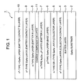
- the thin film crystal wafer (1) comprises a GaAs substrate (2), a buffer layer (3) formed above (2), an n + -type GaAs layer (4) as a collector contact layer, an n-type or non-doping i-type GaAs layer (5) as a collector layer, a p-type GaAs layer (6) as a base layer, an n-type In x Ga 1-x P layer (7) that is an emitter A layer as an emitter layer, and a charge compensation layer (11) formed above (7).
- Figs. 2 and 3 demonstrate the results of measurement of the characteristics of HBT that was manufactured using the thin film crystal wafer (1), the structure of which is shown in Fig. 1.
- Fig. 2 is a graph demonstrating the characteristics of change in collector current IC and base current IB when base voltage VB is changed from 0V to 2 V.
- Fig. 3 is a graph demonstrating the changes in current gain HFE against the changes in the collector current IC. The graph shows the current gain HFE is kept almost constant in relative to the changes in the collector current IC.
- 1x10 -1 is expressed as 1E-01.
- Px10 Q is expressed as PEQ or PeQ in the specification and drawings.
- FIG. 4 shows the structure of a thin film crystal wafer with pn-junction (1') for the conventional HBT shown in Fig. 1 but without the charge compensation layer (11).
- Results of measurement of the characteristics of the thin film crystal wafer (1') shown in Fig. 4 are summarized in Figs. 5 and 6.
- Fig. 5 corresponds to Fig. 2 and Fig. 6 to Fig. 3.
- the axis of abscissas indicates the emitter-base base voltage (base voltage) VB and the axis of ordinates indicates the collector current IC (solid line) and the base current IB (broken line).
- the emitter-collector voltage was set at 2V.
- the axis of abscissas indicates the collector current and the axis of ordinates indicates the current gain HFE.
- the emitter size of HBT is 100 ⁇ mx100 ⁇ m. Measurement conditions of Figs. 2 and 3 are the same as those of Figs. 5 and 6.
- Fig. 7 is a graph of the results of measurement of photoluminescence at room temperature demonstrating a relationship between the emission energy at the band edge of the InGaP layer and the growth temperature, which is a factor of crystal growth. This energy nearly corresponds to the energy of the bandgap. Observation with electron beam diffraction analysis has confirmed that a correlation between the degree of ordering of the natural superlattice and the band edge emission energy. If the lattice constant of InGaP layer is coincident to that of GaAs, the bandgap energy of the InGaP layer without ordering is said to be about 1.92 eV.
- Fig. 15 shows the dependency of the upper and lower limits of sheet doping amount of the charge compensation layer on the doping concentration of the n-type In x Ga 1-x P layer (7) as the emitter A layer.
- Ndemitter is the doping concentration (cm -3 ) of the n-type In x Ga 1-x P layer (7) as the emitter A layer
- the correction factor of the upper limit is approximated to (-2.1E-17 x Ndemitter+26.8)/16.2
- the correction factor of the lower limit is approximated to (-1.7E-18 x Ndemitter+14.9)/6.5.
Landscapes
- Engineering & Computer Science (AREA)
- Microelectronics & Electronic Packaging (AREA)
- Power Engineering (AREA)
- Physics & Mathematics (AREA)
- Condensed Matter Physics & Semiconductors (AREA)
- General Physics & Mathematics (AREA)
- Computer Hardware Design (AREA)
- Ceramic Engineering (AREA)
- Manufacturing & Machinery (AREA)
- Bipolar Transistors (AREA)
- Led Devices (AREA)
Abstract
Description
Δy is a result of subtraction of a value of In composition of the first layer when the first layer coincides with the second layer in lattice constants from a value of the In composition of said first layer,
dInGaP is a thickness of the first layer (nm),
Ndemitter is a carrier concentration of the first layer (cm-3),
dn+GaAs is a thickness of a charge compensation layer (nm) and
NdGaAs is a carrier concentration of the second layer (cm-3).
the correction factor of the upper limit is approximated to
the correction factor of the upper limit is approximated to
the correction factor of the upper limit is
(Eg is bandgap energy (eV) of the first layer at room temperature, and correction of IxΔy is a correction term of the band edge emission energy depending on In composition of InGaP. Δy is obtained by subtracting the In-composition when lattice constant of the first layer coincides with that of the second layer from the In composition of the first layer.
the coefficient C2 is
dInGaP is the thickness (nm)of the first layer, Ndemitter is the carrier concentration (cm-3) of the first layer,
dn+GaAs is the thickness (nm) of the charge compensation layer, and
NdGaAs is the carrier concentration (cm-3) of the second layer.
Claims (9)
- A thin film crystal wafer with pn-junction comprising a first layer of a first conductivity type which is a 3-5 group compound semiconductor represented by a general formula: Inx Gay Alz P (0≤x≤1, 0≤y≤1, 0≤z≤, x+y+z=1), and a second layer of a first conductivity type which is a 3-5 group compound semiconductor represented by a general formula: Inx Gay Alz, As (0≤x≤1, 0≤y≤1, 0≤z≤1, x+y+z=1), said second layer being made above said first layer, and at a heterojunction interface formed between said first layer and said second layer, further comprising a charge compensation layer of a first conductivity type with an impurity concentration higher than that of said first and second layers.
- A thin film crystal wafer with pn-junction according to Claim 1, further comprising a collector layer and a base layer, wherein said first layer is a semiconductor layer which serves as an emitter layer with a band gap larger than said base layer.
- A thin film crystal wafer with pn-junction according to Claim 1 or 2, wherein said first layer is an n-type InGaP layer and said second layer is an n-type Alx Gay As layer (0≤x≤1, 0≤y≤1, x+y=1).
- A thin film crystal wafer with pn-junction according to Claims 1, 2 or 3, wherein an n-type impurity is Si.
- A thin film crystal wafer with pn-junction according to Claims 1, 2, 3 or 4, wherein said charge compensation layer has a thickness of not more than 15 nm and doping amount is greater than 1x1018 cm-3.
- A thin film crystal wafer with pn-junction according to Claims 1, 2, 3, 4 or 5, wherein said first layer has a thickness of not more than 60 nm.
- A thin film crystal wafer with pn-junction according to Claims 1, 2, 3, 4, 5 or 6, wherein a carrier concentration and thickness of said charge compensation layer are controlled depending on a bandgap energy of said first layer.
- A thin film crystal wafer with pn-junction according to Claims 1, 2, 3, 4, 5, 6 or 7, wherein sheet doping amount Ns (cm-2) that is a product of carrier concentration and thickness of said charge compensation layer satisfies:
Δy is obtained by subtracting a value of In composition of the first layer when the first layer coincides with the second layer in lattice constants from a value of the In composition of said first layer,
dInGaP is a thickness of the first layer (nm),
Ndemitter is a carrier concentration of the first layer (cm-3),
dn+GaAs is a thickness of a charge compensation layer (nm), and
NdGaAs is a carrier concentration of the second layer (cm-3). - A thin film crystal wafer with pn-junction according to Claims 1, 2, 3, 4, 5, 6, 7 or 8, wherein epitaxial growth of each of said layers is performed in organometal vapor-phase growth method.
Applications Claiming Priority (2)
| Application Number | Priority Date | Filing Date | Title |
|---|---|---|---|
| JP2001202991 | 2001-07-04 | ||
| JP2001202991 | 2001-07-04 |
Publications (2)
| Publication Number | Publication Date |
|---|---|
| EP1274133A2 true EP1274133A2 (en) | 2003-01-08 |
| EP1274133A3 EP1274133A3 (en) | 2003-01-22 |
Family
ID=19039697
Family Applications (1)
| Application Number | Title | Priority Date | Filing Date |
|---|---|---|---|
| EP02014842A Withdrawn EP1274133A3 (en) | 2001-07-04 | 2002-07-03 | Thin-film crystal wafer having a pn junction and its manufacturing method |
Country Status (5)
| Country | Link |
|---|---|
| US (1) | US6744078B2 (en) |
| EP (1) | EP1274133A3 (en) |
| JP (1) | JP5108694B2 (en) |
| KR (1) | KR100944883B1 (en) |
| TW (1) | TWI277156B (en) |
Families Citing this family (6)
| Publication number | Priority date | Publication date | Assignee | Title |
|---|---|---|---|---|
| US20050077538A1 (en) * | 2003-10-10 | 2005-04-14 | The Regents Of The University Of California | Design methodology for multiple channel heterostructures in polar materials |
| JP2010056250A (en) * | 2008-08-27 | 2010-03-11 | Nec Electronics Corp | Semiconductor device, and method of manufacturing semiconductor device |
| US9466401B1 (en) * | 2009-12-14 | 2016-10-11 | City Labs, Inc. | Tritium direct conversion semiconductor device |
| US10186339B2 (en) | 2014-02-17 | 2019-01-22 | City Labs, Inc. | Semiconductor device for directly converting radioisotope emissions into electrical power |
| US11200997B2 (en) | 2014-02-17 | 2021-12-14 | City Labs, Inc. | Semiconductor device with epitaxial liftoff layers for directly converting radioisotope emissions into electrical power |
| US9799419B2 (en) | 2014-02-17 | 2017-10-24 | City Labs, Inc. | Tritium direct conversion semiconductor device for use with gallium arsenide or germanium substrates |
Citations (4)
| Publication number | Priority date | Publication date | Assignee | Title |
|---|---|---|---|---|
| US5856209A (en) * | 1995-04-25 | 1999-01-05 | Fujitsu Limited | Method of making compound semiconductor device having a reduced resistance |
| JP2000068286A (en) * | 1998-08-20 | 2000-03-03 | Nec Corp | Bipolar transistor |
| US6043520A (en) * | 1998-04-02 | 2000-03-28 | Mitsubishi Denki Kabushiki Kaisha | III-V heterojunction bipolar transistor having a GaAs emitter ballast |
| JP2001326231A (en) * | 2000-05-15 | 2001-11-22 | Nippon Telegr & Teleph Corp <Ntt> | Heterojunction bipolar transistor |
Family Cites Families (9)
| Publication number | Priority date | Publication date | Assignee | Title |
|---|---|---|---|---|
| US5258624A (en) * | 1988-05-27 | 1993-11-02 | U.S. Philips Corp. | Transferred electron effect device |
| US5682046A (en) * | 1993-08-12 | 1997-10-28 | Fujitsu Limited | Heterojunction bipolar semiconductor device and its manufacturing method |
| US5445976A (en) * | 1994-08-09 | 1995-08-29 | Texas Instruments Incorporated | Method for producing bipolar transistor having reduced base-collector capacitance |
| JP3792390B2 (en) | 1998-02-24 | 2006-07-05 | 富士通株式会社 | Semiconductor device and manufacturing method thereof |
| US6563145B1 (en) * | 1999-04-19 | 2003-05-13 | Chang Charles E | Methods and apparatus for a composite collector double heterojunction bipolar transistor |
| JP2001035926A (en) * | 1999-07-19 | 2001-02-09 | Nec Corp | Semiconductor device and fabrication thereof |
| JP2001035859A (en) | 1999-07-21 | 2001-02-09 | Hitachi Cable Ltd | Heterojunction bipolar transistor |
| JP2003007715A (en) * | 2001-06-26 | 2003-01-10 | Nippon Telegr & Teleph Corp <Ntt> | Bipolar transistor |
| JP2003086603A (en) * | 2001-07-04 | 2003-03-20 | Sumitomo Chem Co Ltd | THIN FILM CRYSTAL WAFER HAVING pn JUNCTION AND ITS MANUFACTURING METHOD |
-
2002
- 2002-07-03 EP EP02014842A patent/EP1274133A3/en not_active Withdrawn
- 2002-07-03 TW TW091114895A patent/TWI277156B/en not_active IP Right Cessation
- 2002-07-03 US US10/187,648 patent/US6744078B2/en not_active Expired - Lifetime
- 2002-07-04 KR KR1020020038733A patent/KR100944883B1/en not_active IP Right Cessation
-
2008
- 2008-09-16 JP JP2008235991A patent/JP5108694B2/en not_active Expired - Fee Related
Patent Citations (5)
| Publication number | Priority date | Publication date | Assignee | Title |
|---|---|---|---|---|
| US5856209A (en) * | 1995-04-25 | 1999-01-05 | Fujitsu Limited | Method of making compound semiconductor device having a reduced resistance |
| US6043520A (en) * | 1998-04-02 | 2000-03-28 | Mitsubishi Denki Kabushiki Kaisha | III-V heterojunction bipolar transistor having a GaAs emitter ballast |
| JP2000068286A (en) * | 1998-08-20 | 2000-03-03 | Nec Corp | Bipolar transistor |
| US6355947B1 (en) * | 1998-08-20 | 2002-03-12 | Nec Corporation | Heterojunction bipolar transistor with band gap graded emitter |
| JP2001326231A (en) * | 2000-05-15 | 2001-11-22 | Nippon Telegr & Teleph Corp <Ntt> | Heterojunction bipolar transistor |
Non-Patent Citations (7)
| Title |
|---|
| HARTMANN Q J ET AL: "EFFECT OF COLLECTOR DESIGN ON THE D.C. CHARACTERISTICS OF IN0.49GA0.51P/GAAS HETEROJUNCTION BIPOLAR TRANSISTORS" SOLID STATE ELECTRONICS, ELSEVIER SCIENCE PUBLISHERS, BARKING, GB, vol. 38, no. 12, 1 December 1995 (1995-12-01), pages 2017-2021, XP000580116 ISSN: 0038-1101 * |
| KRISPIN P ET AL: "Interface properties of isotype GaAs/(In,Ga)P/GaAs heterojunctions grown by metalorganic-vapour-phase epitaxy on GaAs" JOURNAL OF CRYSTAL GROWTH, NORTH-HOLLAND PUBLISHING CO. AMSTERDAM, NL, vol. 220, no. 3, December 2000 (2000-12), pages 220-225, XP004223528 ISSN: 0022-0248 * |
| PATENT ABSTRACTS OF JAPAN vol. 2000, no. 06, 22 September 2000 (2000-09-22) & JP 2000 068286 A (NEC CORP), 3 March 2000 (2000-03-03) * |
| PATENT ABSTRACTS OF JAPAN vol. 2002, no. 03, 3 April 2002 (2002-04-03) & JP 2001 326231 A (NIPPON TELEGR & TELEPH CORP), 22 November 2001 (2001-11-22) * |
| SONG J-I ET AL: "CHARACTERISATION OF GAINP/GAAS DOUBLE HETEROJUNCTION BIPOLAR TRANSISTORS WITH DIFFERENT COLLECTOR DESIGNS" ELECTRONICS LETTERS, IEE STEVENAGE, GB, vol. 29, no. 21, 14 October 1993 (1993-10-14), pages 1881-1883, XP000406568 ISSN: 0013-5194 * |
| SONG J-I ET AL: "Millimetre-wave InP/InGaAs heterojunction bipolar transistors with a subpicosecond extrinsic delay time" ELECTRONICS LETTERS, IEE STEVENAGE, GB, vol. 30, no. 5, 3 March 1994 (1994-03-03), pages 456-457, XP006000286 ISSN: 0013-5194 * |
| YONG-HWAN KWON ET AL: "Effect of GaAs/sub y/P/sub 1-y/(0<or=y<1) interlayers on the structural, optical, and electrical characteristics of GaAs/InGaP heterojunction" APPLIED PHYSICS LETTERS, 24 APRIL 2000, AIP, USA, vol. 76, no. 17, pages 2379-2381, XP002221981 ISSN: 0003-6951 * |
Also Published As
| Publication number | Publication date |
|---|---|
| KR100944883B1 (en) | 2010-03-03 |
| JP5108694B2 (en) | 2012-12-26 |
| US6744078B2 (en) | 2004-06-01 |
| KR20030004146A (en) | 2003-01-14 |
| TWI277156B (en) | 2007-03-21 |
| JP2009016867A (en) | 2009-01-22 |
| US20030006427A1 (en) | 2003-01-09 |
| EP1274133A3 (en) | 2003-01-22 |
Similar Documents
| Publication | Publication Date | Title |
|---|---|---|
| US7186624B2 (en) | Bipolar transistor with lattice matched base layer | |
| US6852602B2 (en) | Semiconductor crystal film and method for preparation thereof | |
| US7947557B2 (en) | Heterojunction tunneling field effect transistors, and methods for fabricating the same | |
| US5763905A (en) | Semiconductor device having a passivation layer | |
| US6756615B2 (en) | Heterojunction bipolar transistor and its manufacturing method | |
| CN102428555B (en) | Semiconductor substrate, process for producing semiconductor substrate, and electronic device | |
| US7902571B2 (en) | III-V group compound semiconductor device including a buffer layer having III-V group compound semiconductor crystal | |
| US5682040A (en) | Compound semiconductor device having a reduced resistance | |
| JP5108694B2 (en) | Thin film crystal wafer having pn junction and method for manufacturing the same | |
| US8530934B2 (en) | Integrated circuit structures containing a strain-compensated compound semiconductor layer and methods and systems related thereto | |
| WO2023024549A1 (en) | Gan-based hemt device, device epitaxial structure, and preparation methods therefor | |
| US20070148890A1 (en) | Oxygen enhanced metastable silicon germanium film layer | |
| US6841435B2 (en) | Method for fabricating a GaInP epitaxial stacking structure | |
| JP2013021024A (en) | Transistor element | |
| US6429103B1 (en) | MOCVD-grown emode HIGFET buffer | |
| JP2000068497A (en) | GaN-BASED COMPOUND SEMICONDUCTOR DEVICE | |
| KR101082773B1 (en) | Compound semiconductor element and process for fabricating the same | |
| Hoshi et al. | Low-turn-on-voltage heterojunction bipolar transistors with a C-doped InGaAsSb base grown by metalorganic chemical vapor deposition | |
| CN100492659C (en) | Transistor epitaxial wafer and transistor | |
| JP2003086603A (en) | THIN FILM CRYSTAL WAFER HAVING pn JUNCTION AND ITS MANUFACTURING METHOD | |
| JP2007042936A (en) | Group iii-v compound semiconductor epitaxial wafer | |
| WO2010116701A1 (en) | Method for producing semiconductor substrate and semiconductor substrate | |
| JP4158683B2 (en) | Epitaxial wafer for heterojunction bipolar transistor | |
| JP2007103925A (en) | Semiconductor device and method for manufacturing the same | |
| JP4770130B2 (en) | Epitaxial wafer for field effect transistor and epitaxial wafer for high electron mobility transistor |
Legal Events
| Date | Code | Title | Description |
|---|---|---|---|
| PUAI | Public reference made under article 153(3) epc to a published international application that has entered the european phase |
Free format text: ORIGINAL CODE: 0009012 |
|
| PUAL | Search report despatched |
Free format text: ORIGINAL CODE: 0009013 |
|
| AK | Designated contracting states |
Kind code of ref document: A2 Designated state(s): AT BE BG CH CY CZ DE DK EE ES FI FR GB GR IE IT LI LU MC NL PT SE SK TR |
|
| AX | Request for extension of the european patent |
Free format text: AL;LT;LV;MK;RO;SI |
|
| AK | Designated contracting states |
Kind code of ref document: A3 Designated state(s): AT BE BG CH CY CZ DE DK EE ES FI FR GB GR IE IT LI LU MC NL PT SE SK TR |
|
| AX | Request for extension of the european patent |
Free format text: AL;LT;LV;MK;RO;SI |
|
| 17P | Request for examination filed |
Effective date: 20030627 |
|
| AKX | Designation fees paid |
Designated state(s): DE FR GB |
|
| RAP1 | Party data changed (applicant data changed or rights of an application transferred) |
Owner name: SUMITOMO CHEMICAL COMPANY, LIMITED |
|
| STAA | Information on the status of an ep patent application or granted ep patent |
Free format text: STATUS: THE APPLICATION HAS BEEN WITHDRAWN |
|
| 18W | Application withdrawn |
Effective date: 20060105 |