EP1275470A2 - Device for targeted positioning of a hand-held machine tool - Google Patents
Device for targeted positioning of a hand-held machine tool Download PDFInfo
- Publication number
- EP1275470A2 EP1275470A2 EP02014769A EP02014769A EP1275470A2 EP 1275470 A2 EP1275470 A2 EP 1275470A2 EP 02014769 A EP02014769 A EP 02014769A EP 02014769 A EP02014769 A EP 02014769A EP 1275470 A2 EP1275470 A2 EP 1275470A2
- Authority
- EP
- European Patent Office
- Prior art keywords
- carrier
- tool
- hand
- route guidance
- detecting
- Prior art date
- Legal status (The legal status is an assumption and is not a legal conclusion. Google has not performed a legal analysis and makes no representation as to the accuracy of the status listed.)
- Granted
Links
Images


Classifications
-
- B—PERFORMING OPERATIONS; TRANSPORTING
- B25—HAND TOOLS; PORTABLE POWER-DRIVEN TOOLS; MANIPULATORS
- B25H—WORKSHOP EQUIPMENT, e.g. FOR MARKING-OUT WORK; STORAGE MEANS FOR WORKSHOPS
- B25H7/00—Marking-out or setting-out work
-
- B—PERFORMING OPERATIONS; TRANSPORTING
- B23—MACHINE TOOLS; METAL-WORKING NOT OTHERWISE PROVIDED FOR
- B23Q—DETAILS, COMPONENTS, OR ACCESSORIES FOR MACHINE TOOLS, e.g. ARRANGEMENTS FOR COPYING OR CONTROLLING; MACHINE TOOLS IN GENERAL CHARACTERISED BY THE CONSTRUCTION OF PARTICULAR DETAILS OR COMPONENTS; COMBINATIONS OR ASSOCIATIONS OF METAL-WORKING MACHINES, NOT DIRECTED TO A PARTICULAR RESULT
- B23Q17/00—Arrangements for observing, indicating or measuring on machine tools
- B23Q17/24—Arrangements for observing, indicating or measuring on machine tools using optics or electromagnetic waves
-
- G—PHYSICS
- G01—MEASURING; TESTING
- G01C—MEASURING DISTANCES, LEVELS OR BEARINGS; SURVEYING; NAVIGATION; GYROSCOPIC INSTRUMENTS; PHOTOGRAMMETRY OR VIDEOGRAMMETRY
- G01C15/00—Surveying instruments or accessories not provided for in groups G01C1/00 - G01C13/00
- G01C15/002—Active optical surveying means
- G01C15/004—Reference lines, planes or sectors
Definitions
- the invention relates to a manually manageable device for targeted positioning of a hand-held Tool device, in particular an electric motor drivable drill, a rotary hammer, a milling machine, Circular saw or wall saw, in a given or definable work position or for targeted marking a specified or predefinable working position for a hand-held tool.
- a hand-held Tool device in particular an electric motor drivable drill, a rotary hammer, a milling machine, Circular saw or wall saw, in a given or definable work position or for targeted marking a specified or predefinable working position for a hand-held tool.
- DE 43 36 730 A1 describes a device for a hand-held power tool, namely a drill that placing the power tool in a working position in a predetermined, in particular 90 ° angle one level.
- a device for a hand-held power tool namely a drill that placing the power tool in a working position in a predetermined, in particular 90 ° angle one level.
- electromagnetic waves such as light, Radio frequency waves or visible light, as well as by means of a
- the evaluation device provides the user with information given with regard to the orientation of the tool.
- the publication only deals with the Alignment of the tool with the workpiece.
- the present invention has the object based on the execution or fulfillment of the above
- a manually manageable one Device for the targeted positioning of a handheld tool especially one drill driven by an electric motor, a rotary hammer, a router, circular saw or wall saw, in a given or predefinable work position or for a targeted Mark a predefined or predefinable working position for a handheld tool, with a handheld Carrier for the hand tool or for a marking agent, with a device for detecting the position of the carrier versus a frame of reference, and with a Route guidance device, which under processing of the Location of the data indicating the carrier and of the Data designating a user position Provides information on how to guide the wearer.
- the hand tool is arranged on the carrier, i.e. the carrier, the fastener for the tool device may have or as an attachment for the tool or but as a housing or housing component of the tool device can be formed together with the hand tool the working position moves.
- the marking agent in other words any device by means of which or with the aid of which a marking is made of the surface or in space or on a three-dimensional Object can be made.
- it is Marking agent from a stencil agent, for example an opening formed in the carrier through which a User using a pencil or the like or make a mark on the base can. In this way, the manual is used manageable facility targeted or selectable working position marked, so that then the hand-held tool device can be attached there.
- the route guidance it is necessary that initially by means of the device for detecting the position, that is, the position and orientation of the wearer relative to one Reference system, the current position of the wearer determined and or - if it is already known - into the device, for example via a keyboard.
- This Process which is also called measuring the wearer against one Reference system could be called after a Embodiment of the invention quasi continuously is carried out and the current data is transferred via the position of the carrier used for route guidance and processed.
- the Carrier measured at the beginning and it becomes the Position determination required transformation parameters determined in cooperation with other position providers, for example white measuring ropes, always the latest data on the Location of the carrier for the implementation of the route guidance provide.
- the route guidance is then carried out, i.e. it becomes the actual position of the wearer continuously the TARGET position, namely the working position, and it will be the user in any way Information conveys how or in which direction it Carrier should move to reach the work position.
- the data that the work position (s) to be reached denote, preferably with respect to the same Frame of reference, such as the data indicating the location of the Designate bearer, or it must be appropriate Transformation steps are also taken into account.
- Detecting the position of the carrier is expedient with regard to the tool, for example the drill tip or a marker, referenced so that after Completion of a respective route guidance process the tool or the marker tip is in the desired working position located.
- the device for detecting the position of the carrier comprises at least one, suitably two and for the three-dimensional detection expediently three Distance measuring device (s) and / or Angle measuring device (s).
- a only distance measuring device provided on the carrier would be, in which case the direction should be changeable by for example the distance measuring device by an angle, which would expediently be 90 °, rotatably arranged could be.
- the position of the wearer may cannot be changed. It could then be the removal of the Vehicle to a wall and a floor or to a wall and a ceiling limitation can be determined.
- the device for detecting the position a single Distance measuring device and an angle measuring device, for example in the form of a leveling device which in simplest case through a visually readable Dragonfly device could be formed.
- the carrier it would be conceivable for the carrier to be exactly horizontal is aligned and moved until the Distance measuring device with respect to its position in the Reference system sweeps or captures known point.
- the Device for detecting the position two Distance measuring devices that are at an angle to each other are oriented and includes a leveling device. Under Using such a device then makes it easier Possible, first the carrier by means of Align the leveling device with respect to the horizontal and then by means of the two distance measuring devices Distances to a wall and floor or wall and to determine the ceiling or other objects.
- the device for detecting the position of the carrier can for example based on laser technology Include rangefinders.
- laser measuring devices work in the so-called pulse or phase measurement method and determine based on the emitted and reflected electromagnetic waves the distance of the laser to the reflective object.
- Such devices are known and therefore need no further description here.
- Such a device can be two at a distance measuring rope pulleys arranged from each other, whose one end can be fixed to the hand-held carrier is. By moving the wearer on a wall or in the room the measuring ropes are then rolled out or in. From the respective measuring rope length and the distance between the measuring rollers from each other or by determining the angle of the respective measuring ropes to a connecting straight line between the Measuring rollers can then change the position of the geometric Connection point of the ends of the attached to the carrier Measuring ropes can be calculated.
- the device is the device for detecting the position on the hand-held carrier provided.
- the device comprises advantageously two oriented at an angle to each other Distance measuring devices, preferably in the form of laser-based distance measuring devices. These two Distance measuring devices are then preferably in one Angle of 90 ° to each other.
- the another a leveling device, for example in the form a visually readable dragonfly, provided this Leveling device is arranged such that the Horizontal parallel to one of the orientation axes of the Distance measuring devices runs what the handling of the Device greatly simplified in practice.
- the wearer has a flat support or contact surface a surface or plane enclosing the working position or if the carrier alternatively a three or Multi-point support means includes. Also attached to the carrier advantageously fasteners for elements of the Device for detecting the position of the carrier and / or Fasteners for the tool device and / or Fasteners provided for the marking agent.
- the device for detecting the Position of the carrier to an analog or digital interface include a calculator.
- the Route guidance device an analog or digital Include interface to a computer.
- the calculator can the device according to the invention can be integrated, and he can for example together with the device for detecting the position of the carrier on the carrier itself. It is but it is also conceivable that the computer at an external location, especially as a central computing device at a far distance Place is provided. Then there has to be a communication of the Device for detecting the position of the carrier and the Route guidance device can be created. It would be further conceivable that the route guidance device together with a Computer integrated in the tool device itself or on the Carrier is provided and thus together with the carrier is handled.
- the route guidance device can also be a Display device in the form of a visually perceptible Displays include. But acoustic signal transmitters, that can also generate and output speech signals, be provided.
- the Designating work position i.e. defining data known be and processable in the route guidance device To be available.
- enter this data serve an input keyboard of a computer.
- the user will then in a development of the invention menu-driven for input prompted for data, for example to enter a Distance value of an object from a wall and one further distance value of the object from the ground.
- the input keyboard in the form of a portable computing device be formed by the location of the tool insert the user is brought along.
- the route guidance device or a computer of the Route guidance device or one with the Route guidance device cooperating computer on data, which object geometries relate the central are deposited with a manufacturer of the objects.
- This Access could be over the internet, over radio or over the wired or wireless telecommunications network. It then only has to be ensured that the Data sets from the software used for route guidance and correctly recorded the format on which the software is based and can be processed. Well-known exist Standards that enable such data exchange without any problems do.
- Figure 1 illustrates a number of frequently occurring Basic requirements by a craftsman or fitter must be met. For example, it is common required two mounting positions in the most exact possible prepare relative distance to each other, for example by Drilling a borehole (Figure 1a). Furthermore, it can be required to have an object, such as a Furnishing item, like a cupboard in the case shown, and another item, as in the case shown Sink, at a certain absolute distance from another Arrange object or to a predetermined reference point are (Figure 1b).
- the mounting positions are often incorrect with the outer dimensions of the objects, since Fasteners, such as eyelets or openings, through which then fasteners such as in the assembly process Screws or the like are passed through in one Distance to the outer dimensions of the objects.
- Figure 2 illustrates another basic requirement, according to which an illustrated object 2 at a distance x to one right boundary wall and a distance y to one from one Position floor formed level on a wall 4 is.
- the subject comprises two Attachment eyelets that extend from the top of the item extend away and in the assembled state of screws be penetrated.
- the penetration point for the screws defines the one to be prepared for this requirement Mounting position for item 2, i.e. the working position for a hand-held tool device in the form of a Drill, with which two holes on the corresponding work positions must be created.
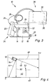
- FIG 3 shows an illustration of a manually manageable Device for the targeted positioning of a Marking means.
- the device 10 comprises a carrier 12 in Shape of a plate.
- a handle 14 for Gripping the carrier 12 provided on the carrier 12 .
- a marking means 16 in the form of a molded tongue 18 with a centering opening 20 is provided, through which a Grains can be passed through, or by means of a Pencils a visually noticeable mark on the Pad can be attached.
- a marking agent would be conceivable. In particular, it could be more complex Embodiments of markers with spray nozzles or the like may be provided.
- the distance measuring devices 22, 24 are Laser rangefinders made from overlays of the emitted and reflected waves the distance of the determine reflecting object in a known manner.
- the respective signal of the distance measuring devices 22, 24 to a computer 30 via data transmission cables 26, 28 given.
- An initially analog or digital measurement signal from Distance measuring device 22, 24 is amplified and then digitized. Or there is a digital measurement signal that given to the computer and processed there.
- a leveling device is on the carrier 12 32 in the form of a visually readable dragonfly like a Spirit level provided. This can preferably be from one electronic dragonfly, the measured value in which Positioning software-supported and therefore automated is included.
- the distance measuring devices 22, 24 and Leveling device 32 form a device 34 for Detecting the position of the wearer in relation to a reference system.
- the computer 30 together with a display 36 or one other, conveying information to a user Facility such as one speaker, one Route guidance device 38 represents.
- the computer controls and calculates the detection of the position of the wearer.
- FIG. 4 illustrates the process of measuring the one in FIG. 4 only schematically shown carrier 12 with the in In connection with Figure 3 described components to a Reference system, which is shown in FIG. 4 with reference numeral 40 is designated.
- This frame of reference 40 becomes, for example through the transition line of a wall 42 to the floor (x-axis) and through the transition line of wall 42 to a lateral one Boundary wall (y-axis) formed.
- To capture the location of the Carrier 12 becomes the carrier 12 with its base or Base plate placed against the wall 42, initially as shown in Figure 4.
- the distance measuring devices 22, 24 then show or measure the distance along the Inclined sections 44, 46.
- the carrier 12 turn until horizontal alignment is achieved (shown in dashed lines in Figure 4). In this position extends the measuring section, i.e. in the case shown Laser light path of one distance measuring device 24 along the horizontal 48 and the other along the Vertical 50.
- the data on the distance of the carrier 12 or advantageously on the marking means 16 referenced distance measuring devices 22, 24 in this horizontally aligned position give the distance of the Beam 12 from the right wall (x) and the distance from the floor (y) and thus denote the exact location, i.e. Position and Orientation of the carrier 12 with respect to the reference system 40.
- Position data can be compared.
- This position data can are either entered into the computer 30 as object data, or they can be read in as object-specific data records are or already exist as data records.
- In the present Case could be a working position that in Figure 4 with the Reference numeral 52 is designated in the form of x, y coordinates with respect to the same reference system 40. It can now a comparison of the actual position of the carrier 12 with these reaching data (x, y coordinates) of the working position 52 be compared.
- FIG. 5 illustrates the measuring principle of another device to detect the position of the carrier using the Measuring wire principle.
- the schematic shows two a base 56 at a certain known distance provided measuring rope pulleys 58, 60 and one in the form of a Dragonfly indicated leveling device 62 for the base 56.
- the measuring rope pulleys 58, 60 each comprise a down or rollable measuring rope 64, 66, which with the respective free end is attached to the carrier 12.
- About each of The rope rope pulley 58, 60 can be pulled off by Implementation of the rotary movement of the measuring rope pulleys in one electrical signal determines the measuring length and accordingly the measurement signal of the distance measuring devices 22, 24 of the Embodiment according to Figure 3 are given to a computer.
- FIG. 7 illustrates another embodiment, two rotating laser scanners 70, 72 with not necessarily horizontal arrangement to each other are provided.
- the Laser scanners 70, 72 scan the with their laser beams Drawing level.
- this laser scanner 70, 72 When using this laser scanner 70, 72 it can be used as Distance measuring devices either, as previously in the Connection with the measuring cable principle explains the distance to the carrier 12 can be determined or it can be via two angular measurements to the unique position of the carrier 12 the base, that is to the geometric connecting line 76 of the two scanners 70, 72 are determined.
- the location of the scanners 70, 72 with reference to the number 40 referred to, as discussed in Figure 6 and shown by touching or attaching the wearer to one wall or floor surface forming an axis of the reference system 40 be determined.
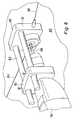
- Figure 8 shows a special and advantageous Embodiment of the device according to the invention, wherein a Power tool in the form of a drill 78 on one Carrier 12 is provided.
- the carrier 12 is via measuring cables 64, 66 based on the measuring cable principle Distance measuring devices connected (but it could also Laser distance measuring sensors are used).
- the carrier 12 comprises a plate-shaped base part 80, two of which are Extend guide rods 82 towards the drill spindle. A fastener slides on these guide rods 82 84 in the form of a clamping device, which the tool neck of the Drill 78 is stuck.
- the carrier 12 After carrying out a route guidance, the carrier 12 is on the wall 86 positioned that the drill bit of the drill 88 is exactly at the work position to be reached.
- the fastening means 84 By applying pressure to the drilling machine 78 in the drilling direction is exerted, it slides with the fastening means 84 with respect to the guide rods 82, and it is thereby exactly on a hole drilled in the working position.
- any prestressing means can be provided, such that when the pressure on the drill 78 decreases, the The drill is pulled out of the borehole again. Further drilling depth limiting means can be provided.
Abstract
Description
Die Erfindung betrifft eine manuell handhabbare Einrichtung zum zielgeführten Positionieren eines handgeführten Werkzeuggeräts, insbesondere einer elektromotorisch antreibbaren Bohrmaschine, eines Bohrhammers, einer Fräse, Handkreissäge oder Mauersäge, in eine vorgegebene oder vorgebbare Arbeitsposition oder zum zielgeführten Markieren einer vorgegebenen oder vorgebbaren Arbeitsposition für ein handgeführtes Werkzeuggerät.The invention relates to a manually manageable device for targeted positioning of a hand-held Tool device, in particular an electric motor drivable drill, a rotary hammer, a milling machine, Circular saw or wall saw, in a given or definable work position or for targeted marking a specified or predefinable working position for a hand-held tool.
In der Anwendung, beispielsweise beim Ausbau von Gebäuden, insbesondere bei der Planung und beim Einbau von Küchen oder beim Aufhängen von Gegenständen an Wänden ergeben sich regelmäßig folgende Basisanforderungen: es soll ein Gegenstand (über in einem bestimmten Abstand zueinander vorgesehene Befestigungsmittel) an einer Wand oder an einem anderen beliebigen Gegenstand entsprechend der Planungsvorgabe befestigt werden. Hierfür müssen dann üblicherweise in einem bestimmten Abstand voneinander und insbesondere in horizontaler Ausrichtung Montagestellen durch Einsatz von handgeführten Werkzeuggeräten geometrisch exakt vorbereitet oder markiert werden. Im Besonderen handelt es sich häufig um die Anbringung von Bohrlöchern zum Einsatz von Befestigungsmitteln.In use, for example when building buildings, especially when planning and installing kitchens or when hanging objects on walls regularly the following basic requirements: it should be an object (over at a certain distance from each other Fasteners) on a wall or on another any object according to the planning requirements be attached. For this purpose, usually in one certain distance from each other and especially in horizontal alignment of assembly points by using hand-held tooling devices are geometrically precisely prepared or be marked. In particular, it is often about the drilling of holes for the use of Fasteners.
Dabei stellt sich regelmäßig die Anforderung, dass im Raum oder an einer Wand zu positionierende Objekte plangerecht in einem bestimmten Abstand zu einer Wand, zu einem Boden oder einer Decke anzubringen sind. Nach Anbringung eines ersten Objektes ergibt sich ggf. die Notwendigkeit, ein zweites Objekt in einem bestimmten Abstand oder in einer bestimmten Orientierung zu dem ersten Objekt anzuordnen. Häufig sollen Montagepositionen entlang einer Geraden, insbesondere horizontal verlaufend, vorbereitet werden, oder es ergibt sich die Anforderung, dass parallel zu einer Bezugslinie in einem bestimmten Abstand zu dieser Bezugslinie eine Anzahl von Montagepositionen vorgesehen werden sollen.There is a regular requirement that in the room or objects to be positioned on a wall according to plan a certain distance from a wall, a floor or be attached to a ceiling. After attaching a first If necessary, there is a need for a second object Object at a certain distance or at a certain distance Arrange orientation to the first object. Frequently should Mounting positions along a straight line, in particular horizontally, be prepared, or it results the requirement that parallel to a reference line in a determined distance from this reference line a number of Mounting positions should be provided.
Bei der Ausführung der vorstehend beschriebenen und nur beispielhaft, jedoch nicht abschließend aufgezählten Anforderungen wird der Handwerker, Installateur oder Monteur vor Ort häufig vor große Probleme gestellt, die auch durch nicht ideale, also unebene Wandfluchten und vor allem Genauigkeitsfehler bei der von Hand, also unter Zuhilfenahme eines Meterstabs ausgeführten Markierarbeiten noch vergrößert werden. Jedenfalls gestaltet sich die Erfüllung der üblichen Basisanforderungen regelmäßig als in höchstem Maße zeitaufwendig, wenn hohe Anforderungen an die Genauigkeit der Ausführung gestellt werden.When performing the above and only exemplary, but not exhaustively listed Craftsmen, plumbers or fitters are required often faced great problems on site, which are also caused by not ideal, so uneven wall alignments and above all Accuracy errors in the manual, so with the help marking work carried out on a yardstick enlarged become. In any case, the fulfillment of the usual Basic requirements regularly as the highest time consuming when high demands on the accuracy of the Execution.
Es wurden bereits Vorschläge unterbreitet, hier Abhilfe zu schaffen. So beschreibt DE 199 02 075 A1 eine Markiereinrichtung, wobei ein horizontal verlaufender Laserstrahl rotiert und demgemäss eine horizontal verlaufende Linie an den umgebenden Wänden eines Raums überstreicht. Ein auf oder an der Wand bewegbares Markiergerät umfasst ein lichtempfindliches Element sowie eine Markiereinrichtung. Jedes Mal, wenn das lichtempfindliche Element von dem rotierenden Laserstrahl getroffen wird, wird eine Farbmarkierung auf die Wand aufgebracht. Es kann so eine horizontale Linie erzeugt werden.Suggestions have already been made to remedy this create. DE 199 02 075 A1 describes one of them Marking device, with a horizontal Laser beam rotates and accordingly a horizontal one Line sweeps across the surrounding walls of a room. On marking device movable on or on the wall comprises a photosensitive element and a marking device. Every time the photosensitive element of that rotating laser beam is hit Color marking applied to the wall. It can be one horizontal line are generated.
DE 43 36 730 A1 beschreibt eine Einrichtung für ein handgeführtes Elektrowerkzeug, nämlich eine Bohrmaschine, die das Ansetzen des Elektrowerkzeugs an eine Arbeitsposition in einem vorgegebenen, insbesondere 90° betragenden Winkel zu einer Ebene ermöglicht. Mittels Sendern und Empfängern für Ultraschall, elektromagnetische Wellen, wie Licht-, Hochfrequenz-Wellen oder sichtbarem Licht, sowie mittels einer Auswerteeinrichtung werden dem Benutzer Informationen hinsichtlich der Orientierung des Werkzeugs gegeben. Die Druckschrift befasst sich jedoch ausschließlich mit der Ausrichtung des Werkzeugs gegenüber dem Werkstück.DE 43 36 730 A1 describes a device for a hand-held power tool, namely a drill that placing the power tool in a working position in a predetermined, in particular 90 ° angle one level. Using transmitters and receivers for Ultrasound, electromagnetic waves, such as light, Radio frequency waves or visible light, as well as by means of a The evaluation device provides the user with information given with regard to the orientation of the tool. The However, the publication only deals with the Alignment of the tool with the workpiece.
Außerdem sind aus DE 43 36 730 A1 und EP 0 306 485 B1 Messeinrichtungen an Elektrohandwerkzeuggeräten bekannt, mittels derer eine horizontale Ausrichtung des Werkzeuggeräts oder die Bohrtiefe gemessen oder angezeigt werden können.Furthermore, DE 43 36 730 A1 and EP 0 306 485 B1 Known measuring devices on electrical hand tool devices, by means of which a horizontal alignment of the tool device or the drilling depth can be measured or displayed.
Hiervon ausgehend liegt der vorliegenden Erfindung die Aufgabe zugrunde, die Ausführung oder Erfüllung der eingangs angeführten Basisanforderungen, die sich beim Einsatz von handgeführten Werkzeuggeräten ergeben, zu erleichtern und zu vereinfachen und vor allem den damit verbundenen Zeitaufwand zu reduzieren.Proceeding from this, the present invention has the object based on the execution or fulfillment of the above The basic requirements mentioned, which are different when using hand-held tool devices result, to facilitate and simplify and above all the time involved to reduce.
Diese Aufgabe wird gelöst durch eine manuell handhabbare Einrichtung zum zielgeführten Positionieren eines handgeführten Werkzeuggeräts, insbesondere einer elektromotorisch antreibbaren Bohrmaschine, eines Bohrhammers, einer Fräse, Handkreissäge oder Mauersäge, in eine vorgegebene oder vorgebbare Arbeitsposition oder zum zielgeführten Markieren einer vorgegebenen oder vorgebbaren Arbeitsposition für ein handgeführtes Werkzeuggerät, mit einem handgeführten Träger für das Handwerkzeuggerät oder für ein Markiermittel, mit einer Vorrichtung zum Erfassen der Lage des Trägers gegenüber einem Bezugssystem, und mit einer Zielführungsvorrichtung, welche unter Verarbeitung von die Lage des Trägers bezeichnenden Daten und von die Arbeitsposition bezeichnenden Daten einem Benutzer Informationen zum Führen des Trägers vermittelt.This task is solved by a manually manageable one Device for the targeted positioning of a handheld tool, especially one drill driven by an electric motor, a rotary hammer, a router, circular saw or wall saw, in a given or predefinable work position or for a targeted Mark a predefined or predefinable working position for a handheld tool, with a handheld Carrier for the hand tool or for a marking agent, with a device for detecting the position of the carrier versus a frame of reference, and with a Route guidance device, which under processing of the Location of the data indicating the carrier and of the Data designating a user position Provides information on how to guide the wearer.
Mit der vorliegenden Erfindung wird also erstmalig eine Einrichtung vorgegeben bzw. die Möglichkeit geschaffen, bei handgeführten Werkzeuggeräten eine vorgegebene oder vorgebbare Arbeitsposition in einer Fläche oder im Raum zielgeführt zu erreichen, ohne dass manuell an der Fläche oder im Raum unter Verwendung eines Meterstabs oder dergleichen in zeitaufwendiger Weise die Arbeitsposition gekennzeichnet werden müsste. Es ist aber auch möglich, unter Verwendung der erfindungsgemäßen Einrichtung auf diese Weise Markierungen zur Kennzeichnung von Arbeitspositionen oder Werkzeugansetzstellen vorzusehen, wiederum ohne dass manuelle Vermessungsvorgänge unter Verwendung eines Meterstabs erforderlich sind.With the present invention, therefore, for the first time Established or created the opportunity at hand-held tool devices a predetermined or predeterminable Work position in a surface or in the room in a targeted manner reach without having to manually on the surface or in the room below Using a yardstick or the like in time-consuming marked the working position should be. But it is also possible to use the device according to the invention in this way markings Identification of work positions or tool attachment points to be provided, again without manual measurement processes using a yardstick are required.
Im einen Fall ist das Handwerkzeuggerät am Träger angeordnet, d.h. der Träger, der Befestigungsmittel für das Werkzeuggerät aufweisen kann oder als Aufsatzteil für das Werkzeuggerät oder aber als Gehäuse oder Gehäusekomponente des Werkzeuggeräts gebildet sein kann, wird zusammen mit dem Handwerkzeuggerät in die Arbeitsposition bewegt. Im anderen Fall ist an dem Träger das Markiermittel, also an sich eine beliebige Einrichtung mittels derer oder unter Zuhilfenahme derer eine Markierung an der Fläche oder auch im Raum bzw. an einem dreidimensionalen Objekt vorgenommen werden kann. Im einfachsten Fall ist das Markiermittel von einem Schablonenmittel, also beispielsweise einer Öffnung in dem Träger gebildet, durch welches ein Benutzer unter Zuhilfenahme eines Bleistifts oder dergleichen oder eines Körners eine Markierung auf der Unterlage vornehmen kann. Auf diese Weise wird also unter Zuhilfenahme der manuell handhabbaren Einrichtung zielgeführt die vorgegebene oder vorgebbare Arbeitsposition markiert, so dass dann danach das handgeführte Werkzeuggerät dort ansetzbar ist.In one case, the hand tool is arranged on the carrier, i.e. the carrier, the fastener for the tool device may have or as an attachment for the tool or but as a housing or housing component of the tool device can be formed together with the hand tool the working position moves. In the other case it is on the carrier the marking agent, in other words any device by means of which or with the aid of which a marking is made of the surface or in space or on a three-dimensional Object can be made. In the simplest case it is Marking agent from a stencil agent, for example an opening formed in the carrier through which a User using a pencil or the like or make a mark on the base can. In this way, the manual is used manageable facility targeted or selectable working position marked, so that then the hand-held tool device can be attached there.
Zur Durchführung der Zielführung ist es jedoch erforderlich, dass zunächst mittels der Vorrichtung zum Erfassen der Lage, also der Position und Orientierung des Trägers gegenüber einem Bezugssystem, die momentane Lage des Trägers ermittelt und oder - wenn sie schon bekannt ist - in die Vorrichtung, beispielsweise über eine Tastatur, eingebbar ist. Dieser Vorgang, der auch als Einmessung des Trägers gegenüber einem Bezugssystem bezeichnet werden könnte, wird nach einer Ausführungsform der Erfindung quasi kontinuierlich durchgeführt und es werden jeweils die aktuellen Daten über die Lage des Trägers zur Zielführung verwendet und verarbeitet. Nach einer anderen Ausführungsform wird der Träger zu Beginn einmal eingemessen und es werden hieraus zur Positionsbestimmung erforderliche Transformationsparameter bestimmt, die im Zusammenwirken mit weiteren Lagegebern, beispielsweiße Messseilen, stets die aktuellen Daten über die Lage des Trägers für die Durchführung der Zielführung bereitstellen.However, to carry out the route guidance it is necessary that initially by means of the device for detecting the position, that is, the position and orientation of the wearer relative to one Reference system, the current position of the wearer determined and or - if it is already known - into the device, for example via a keyboard. This Process, which is also called measuring the wearer against one Reference system could be called after a Embodiment of the invention quasi continuously is carried out and the current data is transferred via the position of the carrier used for route guidance and processed. According to another embodiment, the Carrier measured at the beginning and it becomes the Position determination required transformation parameters determined in cooperation with other position providers, for example white measuring ropes, always the latest data on the Location of the carrier for the implementation of the route guidance provide.
Ausgehend von der nunmehr bekannten Lage des Trägers und unter Verwendung von die zu erreichende Arbeitsposition bezeichnenden Daten wird dann die Zielführung durchgeführt, d.h. es wird kontinuierlich die IST-Position des Trägers mit der SOLL-Position, nämlich der Arbeitsposition, verglichen, und es werden in an sich beliebiger Weise dem Benutzer Informationen vermittelt, wie bzw. in welche Richtung er den Träger bewegen soll, um die Arbeitsposition zu erreichen.Starting from the now known position of the carrier and below Use of the working position to be achieved indicative data, the route guidance is then carried out, i.e. it becomes the actual position of the wearer continuously the TARGET position, namely the working position, and it will be the user in any way Information conveys how or in which direction it Carrier should move to reach the work position.
Die Daten, welche die zu erreichende Arbeitsposition(en) bezeichnen, werden vorzugsweise bezüglich desselben Bezugssystems angegeben, wie die Daten, welche die Lage des Trägers bezeichnen, oder es müssen geeignete Transformationsschritte zusätzlich berücksichtigt werden.The data that the work position (s) to be reached denote, preferably with respect to the same Frame of reference, such as the data indicating the location of the Designate bearer, or it must be appropriate Transformation steps are also taken into account.
Die nachfolgend noch näher zu beschreibende Vorrichtung zum Erfassen der Lage des Trägers ist dabei zweckmäßigerweise bezüglich des Werkzeugs, also beispielsweise der Bohrerspitze oder einer Markierspitze, referenziert, so dass nach Beendigung eines jeweiligen Zielführungsvorgangs das Werkzeug bzw. die Markierspitze sich in der gewünschten Arbeitsposition befindet. The device to be described in more detail below Detecting the position of the carrier is expedient with regard to the tool, for example the drill tip or a marker, referenced so that after Completion of a respective route guidance process the tool or the marker tip is in the desired working position located.
Die Vorrichtung zum Erfassen der Lage des Trägers umfasst wenigstens eine, zweckmäßigerweise zwei und für die dreidimensionale Erfassung zweckmäßigerweise drei Entfernungsmessvorrichtung(en) und/oder Winkelmessvorrichtung(en). Es wäre an sich denkbar, dass eine einzige Entfernungsmessvorrichtung auf dem Träger vorgesehen wäre, wobei dann die Richtung veränderbar sein müsste, indem beispielsweise die Entfernungsmessvorrichtung um einen Winkel, der zweckmäßigerweise 90° betragen würde, verdrehbar angeordnet sein könnte. Währenddessen darf jedoch die Lage des Trägers nicht verändert werden. Es könnte dann die Entfernung des Trägers zu einer Wand und einem Boden oder zu einer Wand und einer Deckenbegrenzung ermittelt werden. Es wäre auch denkbar, dass die Vorrichtung zum Erfassen der Lage eine einzige Entfernungsmessvorrichtung und eine Winkelmessvorrichtung, beispielsweise in Form einer Horizontiervorrichtung, die im einfachsten Fall durch eine visuell ablesbare Libellenvorrichtung gebildet sein könnte, umfasst. Solchenfalls wäre es denkbar, dass der Träger exakt horizontal ausgerichtet wird und solange verschoben wird, bis die Entfernungsmessvorrichtung einen bezüglich seiner Lage im Bezugssystem bekannten Punkt überstreicht oder erfasst.The device for detecting the position of the carrier comprises at least one, suitably two and for the three-dimensional detection expediently three Distance measuring device (s) and / or Angle measuring device (s). In itself, it would be conceivable that a only distance measuring device provided on the carrier would be, in which case the direction should be changeable by for example the distance measuring device by an angle, which would expediently be 90 °, rotatably arranged could be. Meanwhile, the position of the wearer may cannot be changed. It could then be the removal of the Vehicle to a wall and a floor or to a wall and a ceiling limitation can be determined. It would also be conceivable that the device for detecting the position a single Distance measuring device and an angle measuring device, for example in the form of a leveling device which in simplest case through a visually readable Dragonfly device could be formed. In such a case, it would be conceivable for the carrier to be exactly horizontal is aligned and moved until the Distance measuring device with respect to its position in the Reference system sweeps or captures known point.
Als besonders vorteilhaft hat es sich erwiesen, wenn die Vorrichtung zum Erfassen der Lage zwei Entfernungsmessvorrichtungen, die in einem Winkel zueinander orientiert sind und eine Horizontiervorrichtung umfasst. Unter Verwendung einer solchen Vorrichtung ist es dann in einfacher Weise möglich, zunächst den Träger mittels der Horizontiervorrichtung bezüglich der Horizontalen auszurichten und dann mittels der beiden Entfernungsmessvorrichtungen die Entfernungen zu einer Wand und einem Fußboden oder einer Wand und der Decke oder auch zu sonstigen Objekten zu bestimmen.It has proven to be particularly advantageous if the Device for detecting the position two Distance measuring devices that are at an angle to each other are oriented and includes a leveling device. Under Using such a device then makes it easier Possible, first the carrier by means of Align the leveling device with respect to the horizontal and then by means of the two distance measuring devices Distances to a wall and floor or wall and to determine the ceiling or other objects.
Die Vorrichtung zum Erfassen der Lage des Trägers kann beispielsweise auf Lasertechnik beruhende Entfernungsmessgeräte umfassen. Solche Lasermessgeräte arbeiten im sog. Impuls- oder im Phasenmessverfahren und ermitteln anhand der ausgesandten und reflektierten elektromagnetischen Wellen die Entfernung des Lasers zum reflektierenden Objekt. Derartige Geräte sind bekannt und bedürfen daher hier keiner weiteren Beschreibung.The device for detecting the position of the carrier can for example based on laser technology Include rangefinders. Such laser measuring devices work in the so-called pulse or phase measurement method and determine based on the emitted and reflected electromagnetic waves the distance of the laser to the reflective object. Such devices are known and therefore need no further description here.
Des weiteren sind Geräte bekannt, die auf dem Messseilprinzip beruhen. Eine derartige Vorrichtung kann zwei im Abstand voneinander angeordnete Messseilrollen umfassen, deren jeweiliges eine Ende an dem handgeführten Träger fixierbar ist. Durch die Bewegung des Trägers an einer Wand oder im Raum werden dann die Messseile aus- bzw. eingerollt. Aus der jeweiligen Messseillänge und dem Abstand der Messrollen voneinander oder auch unter Bestimmung des Winkels der jeweiligen Messseile zu einer Verbindungsgeraden zwischen den Messrollen kann dann die Position des geometrischen Verbindungspunktes der am Träger befestigten Enden der Messseile errechnet werden.Furthermore, devices are known which operate on the measuring cable principle based. Such a device can be two at a distance measuring rope pulleys arranged from each other, whose one end can be fixed to the hand-held carrier is. By moving the wearer on a wall or in the room the measuring ropes are then rolled out or in. From the respective measuring rope length and the distance between the measuring rollers from each other or by determining the angle of the respective measuring ropes to a connecting straight line between the Measuring rollers can then change the position of the geometric Connection point of the ends of the attached to the carrier Measuring ropes can be calculated.
Es wäre ferner denkbar, dass anstelle der Messrollen zwei insbesondere rotierbare Laserscanner verwendet werden, die beispielsweise auf dem Boden an einer Wand vorgesehen werden und eine parallel zu der Wand verlaufende Ebene abscannen. Wird nun an dem in der Fläche der Wand bewegten Träger eine Reflexionseinrichtung vorgesehen, so kann zu jedem Zeitpunkt die Entfernung und/oder der Winkel dieser Reflexionseinrichtung von den jeweiligen Laserscannern ermittelt werden. Hieraus kann bei bekanntem Abstand und/oder Winkel der Laserscanner voneinander, der auch unter Verwendung der Laserscanner ermittelt werden kann, wiederum der geometrische Ort des Trägers bezüglich einer durch die beiden Laserscanner gebildeten Basis errechnet werden. Wenn zudem Horizontiervorrichtungen an wenigstens einem der Lasersensoren verwendet werden, so lässt sich auch die Orientierung dieser Basis bezüglich der Horizontalen oder auch bezüglich einer durch einen Fußboden gebildeten Ebene ermitteln. Entsprechendes gilt auch für Vorrichtungen, die auf dem vorstehend beschriebenen Messseilprinzip beruhen.It would also be conceivable that two instead of the measuring rollers in particular rotatable laser scanners are used, the for example on the floor on a wall and scan a plane parallel to the wall. Is now a on the moving in the surface of the wall Reflection device is provided at any time the distance and / or the angle of this Reflection device from the respective laser scanners be determined. With a known distance and / or Angle of the laser scanner from each other, which is also using the laser scanner can be determined, again the geometric location of the carrier with respect to one by the two Laser scanner formed base can be calculated. If also Leveling devices on at least one of the laser sensors the orientation of these can also be used Basis with respect to the horizontal or also with respect to one determine the level formed by a floor. The same applies to devices based on the measuring cable principle described above based.
Bei einer besonders einfach handhabbaren und daher vorteilhaften Ausführungsform der erfindungsgemäßen Einrichtung ist die Vorrichtung zum Erfassen der Lage an dem handgeführten Träger vorgesehen. Die Vorrichtung umfasst vorteilhafterweise zwei in einem Winkel zueinander orientierte Entfernungsmessvorrichtungen, vorzugsweise in der Form von laserbasierten Entfernungsmessgeräten. Diese beiden Entfernungsmessvorrichtungen sind dann vorzugsweise in einem Winkel von 90° zueinander orientiert. Vorzugsweise ist des weiteren eine Horizontiervorrichtung, beispielsweise in Form einer visuell ablesbaren Libelle, vorgesehen, wobei diese Horizontiervorrichtung derart angeordnet ist, dass die Horizontale parallel zu einer der Orientierungsachsen der Entfernungsmessvorrichtungen verläuft, was die Handhabung des Geräts in der Praxis stark vereinfacht.With a particularly easy to handle and therefore advantageous embodiment of the invention The device is the device for detecting the position on the hand-held carrier provided. The device comprises advantageously two oriented at an angle to each other Distance measuring devices, preferably in the form of laser-based distance measuring devices. These two Distance measuring devices are then preferably in one Angle of 90 ° to each other. Preferably, the another a leveling device, for example in the form a visually readable dragonfly, provided this Leveling device is arranged such that the Horizontal parallel to one of the orientation axes of the Distance measuring devices runs what the handling of the Device greatly simplified in practice.
Des weiteren erweist es sich als vorteilhaft und konstruktiv einfach, wenn der Träger eine ebene Auf- oder Anlagefläche an eine die Arbeitsposition einschließende Fläche oder Ebene aufweist, oder wenn der Träger alternativ hierzu ein dreioder Mehrpunktauflagemittel umfasst. Ferner sind an den Träger vorteilhafterweise Befestigungsmittel für Elemente der Vorrichtung zum Erfassen der Lage des Trägers und/oder Befestigungsmittel für das Werkzeuggerät und/oder Befestigungsmittel für das Markiermittel vorgesehen.Furthermore, it proves to be advantageous and constructive easy if the wearer has a flat support or contact surface a surface or plane enclosing the working position or if the carrier alternatively a three or Multi-point support means includes. Also attached to the carrier advantageously fasteners for elements of the Device for detecting the position of the carrier and / or Fasteners for the tool device and / or Fasteners provided for the marking agent.
Um die Daten, welche die Lage des Trägers beschreiben, verarbeiten zu können, kann die Vorrichtung zum Erfassen der Lage des Trägers eine analoge oder digitale Schnittstelle zu einem Rechner umfassen. In entsprechender Weise kann die Zielführungsvorrichtung eine analoge oder digitale Schnittstelle zu einem Rechner umfassen. Der Rechner kann in die erfindungsgemäße Einrichtung integriert sein, und er kann sich beispielsweise zusammen mit der Vorrichtung zum Erfassen der Lage des Trägers auf dem Träger selbst befinden. Es ist aber auch denkbar, dass der Rechner an externer Stelle, insbesondere als Zentralrecheneinrichtung an weit entfernter Stelle vorgesehen ist. Es muss dann eine Kommunikation der Vorrichtung zum Erfassen der Lage des Trägers und der Zielführungsvorrichtung geschaffen werden. Es wäre ferner denkbar, dass die Zielführungsvorrichtung zusammen mit einem Rechner in das Werkzeuggerät selbst integriert oder auf dem Träger vorgesehen ist und damit zusammen mit dem Träger gehandhabt wird.In order for the data describing the position of the wearer To be able to process, the device for detecting the Position of the carrier to an analog or digital interface include a calculator. In a corresponding manner, the Route guidance device an analog or digital Include interface to a computer. The calculator can the device according to the invention can be integrated, and he can for example together with the device for detecting the position of the carrier on the carrier itself. It is but it is also conceivable that the computer at an external location, especially as a central computing device at a far distance Place is provided. Then there has to be a communication of the Device for detecting the position of the carrier and the Route guidance device can be created. It would be further conceivable that the route guidance device together with a Computer integrated in the tool device itself or on the Carrier is provided and thus together with the carrier is handled.
Die Zielführungsvorrichtung kann ferner eine Anzeigevorrichtung in Form eines visuell wahrnehmbaren Displays umfassen. Es können aber auch akustische Signalgeber, die auch Sprachsignale erzeugen und ausgeben können, vorgesehen sein.The route guidance device can also be a Display device in the form of a visually perceptible Displays include. But acoustic signal transmitters, that can also generate and output speech signals, be provided.
Zur Ausführung einer Zielführung müssen jeweils die Arbeitsposition bezeichnende, d.h. definierende Daten bekannt sein und in der Zielführungsvorrichtung verarbeitbar zur Verfügung stehen. Zur Eingabe dieser Daten kann beispielsweise eine Eingabetastatur eines Rechners dienen. Der Benutzer wird dann in Weiterbildung der Erfindung menuegesteuert zur Eingabe von Daten aufgefordert, beispielsweise zur Eingabe eines Abstandswerts eines Gegenstands von einer Wand und eines weiteren Abstandswerts des Gegenstands vom Boden. Hierfür kann die Eingabetastatur in Form einer tragbaren Rechnereinrichtung ausgebildet sein, die an den Ort des Werkzeugeinsatzes durch den Benutzer mitgebracht wird. Es ist aber auch denkbar und vorteilhaft, dass insbesondere bei komplexen Anforderungen, wenn also eine Vielzahl von vorgegebenen Arbeitspositionen zu berücksichtigen sind, etwa bei der Anbringung großvolumiger Gegenstände, wie Hängeschränke, mit einer Vielzahl von Befestigungsmitteln, die hierfür erforderlichen Daten über die Vielzahl von Arbeitspositionen in anderer Weise für die Ausführung der Zielführung zur Verfügung stehen. So wäre es denkbar und vorteilhaft, dass diese Informationen in Form von Datensätzen über die jeweilige Objektgeometrie zur Verfügung stehen und beispielsweise vom Hersteller der zu positionierenden und anzubringenden Vorrichtungen datenverarbeitbar auf einem Datenträger oder Chip zur Verfügung gestellt werden. Es wäre dann z.B. hinreichend, dass der Benutzer lediglich den Abstand, beispielsweise eines an einer Wand zu montierenden Objekts zu einer Begrenzungswand und den Abstand des Objekts zum Boden eingibt und dann anhand einer eingegebenen oder zugeladenen Objektgeometrie sämtliche Arbeitspositionen, die von dem Werkzeuggerät angefahren werden müssen, für die Zielführung zur Verfügung stehen.To carry out route guidance, the Designating work position, i.e. defining data known be and processable in the route guidance device To be available. For example, to enter this data serve an input keyboard of a computer. The user will then in a development of the invention menu-driven for input prompted for data, for example to enter a Distance value of an object from a wall and one further distance value of the object from the ground. For this can the input keyboard in the form of a portable computing device be formed by the location of the tool insert the user is brought along. But it is also conceivable and advantageous that especially with complex requirements, if so a variety of predetermined work positions are to be taken into account, for example when installing larger volumes Items, such as wall cabinets, with a variety of Fasteners, the data required for this Variety of work positions in other ways for the Execution of route guidance are available. So it would be conceivable and advantageous that this information in the form of Data records about the respective object geometry are available stand and for example from the manufacturer of the positioning and attaching devices data processable on a data carrier or chip Will be provided. It would then be e.g. sufficient that the user only indicates the distance, for example one a wall-mounted object to a boundary wall and enter the distance of the object to the ground and then based on all entered or loaded object geometry Working positions that are approached by the machine tool must be available for route guidance.
In noch weiterer Ausbildung der Erfindung wäre es denkbar, dass die Zielführungsvorrichtung bzw. ein Rechner der Zielführungsvorrichtung oder ein mit der Zielführungsvorrichtung kooperierender Rechner auf Daten, welche Objektgeometrien betreffen, zurückgreift, die zentral bei einem Hersteller der Objekte hinterlegt sind. Dieser Zugriff könnte über das Internet, über Funk oder über das drahtgebundene oder drahtlose Telekommunikationsnetz erfolgen. Es muss dann lediglich sichergestellt werden, dass die Datensätze von der für die Zielführung verwandten Software und dem der Software zugrundeliegenden Format korrekt erfasst und verarbeitet werden können. So existieren jedoch bekannte Standards, die einen solchen Datenaustausch problemlos möglich machen.In a still further embodiment of the invention, it would be conceivable that the route guidance device or a computer of the Route guidance device or one with the Route guidance device cooperating computer on data, which object geometries relate, the central are deposited with a manufacturer of the objects. This Access could be over the internet, over radio or over the wired or wireless telecommunications network. It then only has to be ensured that the Data sets from the software used for route guidance and correctly recorded the format on which the software is based and can be processed. Well-known exist Standards that enable such data exchange without any problems do.
Weitere Merkmale, Einzelheiten und Vorteile der Erfindung ergeben sich aus den beigefügten Patentansprüchen und aus der zeichnerischen Darstellung und nachfolgenden Beschreibung bevorzugter Ausführungsformen der erfindungsgemäßen Einrichtung. In der Zeichnung zeigt:
- Figur 1a bis e
- die Darstellung von sich häufig stellenden Basisanforderungen;
Figur 2- eine bildliche Verdeutlichung einer bestimmten Basisanforderung;
- Figur 3
- eine schematische Darstellung eines Trägers mit zwei Entfernungsmessvorrichtungen;
Figur 4- eine Veranschaulichung der Arbeitsweise einer Einrichtung mit den Komponenten nach Figur 3;
- Figur 5
- eine schematische Darstellung des Messseilprinzips zur Bestimmung der Lage;
- Figur 6
- Verdeutlichung der Arbeitsweise einer auf dem Messseilprinzip beruhenden Einrichtung;
Figur 7- schematische Darstellung einer mittels Laserscanner arbeitenden Einrichtung; und
- Figur 8
- eine Ausführungsform einer erfindungsgemäßen Einrichtung zum zielgeführten Positionieren einer Bohrmaschine.
- Figure 1a to e
- the presentation of frequently occurring basic requirements;
- Figure 2
- an illustration of a specific basic requirement;
- Figure 3
- a schematic representation of a carrier with two distance measuring devices;
- Figure 4
- an illustration of the operation of a device with the components of Figure 3;
- Figure 5
- a schematic representation of the measuring cable principle for determining the position;
- Figure 6
- Clarification of the functioning of a device based on the measuring cable principle;
- Figure 7
- schematic representation of a device using a laser scanner; and
- Figure 8
- an embodiment of a device according to the invention for targeted positioning of a drilling machine.
Figur 1 verdeutlicht eine Anzahl von sich häufig stellenden Basisanforderungen, die von einem Handwerker oder Monteur erfüllt werden müssen. So ist es beispielsweise häufig erforderlich, zwei Montagepositionen in möglichst exaktem relativem Abstand zueinander vorzubereiten, etwa durch Anbringung eines Bohrlochs (Figur 1a). Des weiteren kann es erforderlich sein, dass ein Objekt, etwa ein Einrichtungsgegenstand, wie im dargestellten Fall ein Schrank, und ein weiterer Gegenstand, wie im dargestellten Fall eine Spüle, in einem bestimmten absoluten Abstand zu einem anderen Gegenstand oder zu einem vorgegebenen Bezugspunkt anzuordnen sind (Figur 1b). Häufig stimmen die Montagepositionen nicht mit den Außenabmessungen der Objekte überein, da sich Befestigungsmittel, wie beispielsweise Ösen oder Öffnungen, durch welche dann beim Montageprozess Befestigungselemente wie Schrauben oder dergleichen hindurchgeführt werden, in einem Abstand zu den Außenabmessungen der Objekte befinden.Figure 1 illustrates a number of frequently occurring Basic requirements by a craftsman or fitter must be met. For example, it is common required two mounting positions in the most exact possible prepare relative distance to each other, for example by Drilling a borehole (Figure 1a). Furthermore, it can be required to have an object, such as a Furnishing item, like a cupboard in the case shown, and another item, as in the case shown Sink, at a certain absolute distance from another Arrange object or to a predetermined reference point are (Figure 1b). The mounting positions are often incorrect with the outer dimensions of the objects, since Fasteners, such as eyelets or openings, through which then fasteners such as in the assembly process Screws or the like are passed through in one Distance to the outer dimensions of the objects.
Ein weiteres sich häufig stellendes Problem ist die Anordnung mehrerer Montagepositionen auf einer Geraden (Figur 1c). Häufig muss eine lineare Anordnung von Montagepositionen in einem bestimmten Abstand zu einer Bezugslinie, beispielsweise einer Übergangslinie zwischen Decke und Wand, angeordnet werden (Figur 1d). Oder es stellt sich die Aufgabe, dass Montagepositionen und damit Arbeitspositionen für ein Werkzeuggerät bezüglich eine Ebene bildenden Koordinaten oder auch Raumkoordinaten festgelegt sind und angefahren werden müssen.Another common problem is placement several mounting positions on a straight line (Figure 1c). Often, a linear arrangement of assembly positions in a certain distance from a reference line, for example a transition line between the ceiling and the wall be (Figure 1d). Or the task arises that Assembly positions and thus working positions for one Tool device with respect to coordinates forming a plane or spatial coordinates are also defined and approached have to.
Figur 2 veranschaulicht eine weitere Basisanforderung, wonach
ein dargestellter Gegenstand 2 in einem Abstand x zu einer
rechten Begrenzungswand und einem Abstand y zu einer von einem
Fußboden gebildeten Ebene an einer Wand 4 zu positionieren
ist. Der Gegenstand umfasst im dargestellten Fall zwei
Befestigungsösen, die sich von der Oberseite des Gegenstands
weg erstrecken und im montierten Zustand von Schrauben
durchgriffen werden. Der Durchgriffspunkt für die Schrauben
definiert bei dieser Anforderung die vorzubereitende
Montageposition für den Gegenstand 2, d.h. die Arbeitsposition
für ein handgeführtes Werkzeuggerät in Form einer
Bohrmaschine, mit welchem zwei Bohrlöcher an den
entsprechenden Arbeitspositionen zu erstellen sind.Figure 2 illustrates another basic requirement, according to which
an illustrated
Figur 3 zeigt eine Darstellung einer manuell handhabbaren
Einrichtung zum zielgeführten Positionieren eines
Markiermittels. Die Einrichtung 10 umfasst einen Träger 12 in
Form einer Platte. Auf den Träger 12 ist ein Handgriff 14 zum
Ergreifen des Trägers 12 vorgesehen. Ferner ist an den Träger
ein Markiermittel 16 in Form einer angeformten Zunge 18 mit
einer zentrierenden Öffnung 20 vorgesehen, durch welche ein
Körner hindurchgeführt werden kann, oder mittels eines
Bleistifts eine visuell wahrnehmbare Markierung auf der
Unterlage angebracht werden kann. Es versteht sich, dass auch
jede andere beliebige Ausführungsform eines Markiermittels
denkbar wäre. Es könnten insbesondere aufwendigerere
Ausführungsformen von Markiermitteln mit Spritzdüsen oder
dergleichen vorgesehen sein.Figure 3 shows an illustration of a manually manageable
Device for the targeted positioning of a
Marking means. The
Auf dem Träger 12 sind zwei Entfernungsmessvorrichtungen 22
und 24 in einem bevorzugten Winkel von 90° zueinander montiert.
Bei den Entfernungsmessvorrichtungen 22, 24 handelt es sich um
Laserentfernungsmessgeräte, die aus Überlagerungen der
ausgesandten und reflektierten Wellen die Entfernung des
reflektierenden Objekts in bekannter Weise ermitteln. Das
jeweilige Signal der Entfernungsmessvorrichtungen 22, 24 wird
über Datenübertragungskabel 26, 28 an einen Rechner 30
gegeben. Ein zunächst analoges oder digitales Messsignal der
Entfernungsmessvorrichtung 22, 24 wird verstärkt und dann
digitalisiert. Oder es liegt ein digitales Messsignal vor, das
an den Rechner gegeben und dort weiterverarbeitet wird.There are two
Des weiteren ist auf dem Träger 12 eine Horizontiervorrichtung
32 in Form einer visuell ablesbaren Libelle wie bei einer
Wasserwaage vorgesehen. Diese kann vorzugsweise von einer
elektronischen Libelle gebildet sein, deren Messwert in die
Positionierung softwaregestützt und daher automatisiert
einbezogen wird.Furthermore, a leveling device is on the
Es wird ausdrücklich darauf hingewiesen, dass anstelle des Markiermittels 16 oder zusätzlich zu dem Markiermittel 16 an dem Träger 12 eine Halterung für ein handgeführtes Werkzeuggerät vorgesehen sein könnte.It is expressly pointed out that instead of the Marking means 16 or in addition to the marking means 16 the carrier 12 a holder for a hand-held Tool device could be provided.
Die Entfernungsmessvorrichtungen 22, 24 und die
Horizontiervorrichtung 32 bilden eine Vorrichtung 34 zum
Erfassen der Lage des Trägers gegenüber einem Bezugssystem.
Der Rechner 30 stellt zusammen mit einem Display 36 oder einer
sonstigen, Informationen an einen Benutzer vermittelnden
Einrichtung, wie z.B. ein Lautsprecher, eine
Zielführungsvorrichtung 38 dar. Der Rechner steuert und
berechnet die Erfassung der Lage des Trägers. The
Figur 4 verdeutlicht den Vorgang des Einmessens des in Figur 4
nur schematisch dargestellten Trägers 12 mit den im
Zusammenhang mit Figur 3 beschriebenen Komponenten zu einem
Bezugssystem, was in Figur 4 mit dem Bezugszeichen 40
bezeichnet ist. Dieses Bezugssystem 40 wird beispielsweise
durch die Übergangslinie einer Wand 42 zum Boden (x-Achse) und
durch die Übergangslinie der Wand 42 zu einer seitlichen
Begrenzungswand (y-Achse) gebildet. Zum Erfassen der Lage des
Trägers 12 wird der Träger 12 mit seiner Basis- oder
Grundplatte gegen die Wand 42 gelegt, und zwar zunächst so wie
in Figur 4 dargestellt. Die Entfernungsmessvorrichtungen 22,
24 zeigen bzw. messen dann die Entfernung entlang der
Schrägstrecken 44, 46. Der Benutzer kann nun unter
Zuhilfenahme der Horizontiervorrichtung 32 den Träger 12
derart drehen, bis eine horizontale Ausrichtung erreicht ist
(in Figur 4 gestrichelt dargestellt). In dieser Position
erstreckt sich die Messstrecke, also im dargestellten Fall die
Laserlichtstrecke der einen Entfernungsmessvorrichtung 24
entlang der Horizontalen 48 und die andere entlang der
Vertikalen 50. Die Daten über die Entfernung des Trägers 12
bzw. der vorteilhafterweise auf das Markiermittel 16
referenzierten Entfernungsmessvorrichtungen 22, 24 in dieser
horizontal ausgerichteten Position geben also den Abstand des
Trägers 12 von der rechten Wand (x) und den Abstand vom Boden
(y) an und bezeichnen somit die exakte Lage, d.h. Position und
Orientierung des Trägers 12 bezüglich des Bezugssystems 40.
Wenn diese Daten nun über Datenübertragungskabel 26, 28 oder
über beliebige Schnittstellen, insbesondere über
bidirektionale Funkeinrichtungen oder in sonstiger Weise an
einen Rechner gegeben werden, so können diese Daten zur
Ausführung einer Zielführung mit zu erreichenden
Positionsdaten verglichen werden. Diese Positionsdaten können
entweder als Objektdaten in den Rechner 30 eingegeben werden,
oder sie können als objektspezifische Datensätze eingelesen
werden oder bereits als Datensätze vorliegen. Im vorliegenden
Fall könnte eine Arbeitsposition, die in Figur 4 mit dem
Bezugszeichen 52 bezeichnet ist, in Form von x-, y-Koordinaten
bezüglich desselben Bezugssystems 40 vorliegen. Es kann nun
ein Vergleich der IST-Position des Trägers 12 mit diesen zu
erreichenden Daten (x-, y-Koordinaten) der Arbeitsposition 52
verglichen werden. In Abhängigkeit von der Abweichung kann
dann auf dem Display 36 des Rechners 30 nach Figur 3, oder wie
in Figur 4 angedeutet, auf einem Display 54, welches auf dem
Träger 12 vorgesehen ist, Informationen an den Benutzer
vermittelt werden, wie er den Träger 12 zu führen hat, damit
die Arbeitsposition 52 erreicht wird.FIG. 4 illustrates the process of measuring the one in FIG. 4
only schematically shown
Figur 5 verdeutlicht das Messprinzip einer anderen Vorrichtung
zum Erfassen der Lage des Trägers unter Verwendung des
Messseilprinzips. Die schematische Darstellung zeigt zwei auf
einer Basis 56 in einem bestimmten bekannten Abstand
vorgesehene Messseilrollen 58, 60 sowie eine in Form einer
Libelle angedeutete Horizontiervorrichtung 62 für die Basis
56. Die Messseilrollen 58, 60 umfassen jeweils ein ab- bzw.
ausrollbares Messseil 64, 66, welches mit dem jeweiligen
freien Ende am Träger 12 befestigt ist. Über die jeweils von
der Messseilrolle 58, 60 abgezogene Seillänge kann durch
Umsetzung der Drehbewegung der Messseilrollen in ein
elektrisches Signal die Messlänge ermittelt und entsprechend
dem Messsignal der Entfernungsmessvorrichtungen 22, 24 der
Ausführungsform nach Figur 3 an einen Rechner gegeben werden.Figure 5 illustrates the measuring principle of another device
to detect the position of the carrier using the
Measuring wire principle. The schematic shows two
a
Der im Zusammenhang mit Figur 4 beschriebene Prozess der
Lagebestimmung des Trägers, das Einmessen des Trägers
bezüglich eines Bezugssystems, ist für das Messseilprinzip in
Figur 6 dargestellt. Zum Einmessen der Lage der Basis 56 und
der Messseilrollen 58, 60 wird der Träger mit seinem
Referenzpunkt im dargestellten Fall an die rechte
Begrenzungswand 68 geführt. Es kann nun aus der Länge des
Messseils 64, 66 und bei bekanntem Abstand der Messseilrollen
58, 60 entlang der Basis 56 der Abstand der
Messseilvorrichtung von der rechten Begrenzungswand 68
ermittelt werden. Dies ist aber erforderlich, um eine
momentane Lage des Trägers und der Messeilvorrichtung
bezüglich des wiederum mit dem Bezugszeichen 40 bezeichneten
und in derselben Weise aufgespannten Bezugssystems zu
erreichen. Nach diesem Einmessvorgang kann über die
Entfernungsmessvorrichtungen, die im vorliegenden Fall durch
die Messseilrollen 58, 60 gebildet werden, wiederum zu jedem
beliebigen Zeitpunkt die momentane Position des Trägers
bezüglich dem Bezugssystem 40 ermittelt und zur Ausführung
einer Zielführung herangezogen werden.The process described in connection with Figure 4
Determining the position of the wearer, measuring the wearer
with respect to a reference system, is for the measuring cable principle in
Figure 6 shown. For measuring the position of the
Figur 7 verdeutlicht eine weitere Ausführungsform, wobei zwei
rotierende Laserscanner 70, 72 mit nicht notwendigerweise
horizontaler Anordnung zueinander vorgesehen sind. Die
Laserscanner 70, 72 scannen mit ihren Laserstrahlen die
Zeichnungsebene. Am Gehäuse des Scanners 70 ist eine
Horizontiervorrichtung 74 vorgesehen, die nach horizontaler
Ausrichtung des Scanners 70 eine Bestimmung des Winkels
zwischen der geometrischen Verbindungslinie zum zweiten
Laserscanner 72 und der Horizontalen möglich ist. Man kann bei
bekannter Basisentfernung entweder 2 Strecken- oder 2
Winkelmessungen ausführen, um die Lage des Trägers zu
bestimmen. Im Prinzip könnte mittels eines einzigen
Laserscanners mit einer Horizontiervorrichtung eine
Positionsbestimmung des Trägers durchgeführt werden.Figure 7 illustrates another embodiment, two
Es kann bei Anwendung dieser Laserscanner 70, 72 als
Entfernungsmessvorrichtungen entweder, wie vorausgehend im
Zusammenhang mit dem Messseilprinzip erläutert, die Entfernung
zu dem Träger 12 jeweils ermittelt werden oder es kann über
zwei Winkelmessungen die eindeutige Position des Trägers 12 zu
der Basis, also zu der geometrischen Verbindungslinie 76 der
beiden Scanner 70, 72 ermittelt werden. Die Lage der Scanner
70, 72 bezüglich des wiederum mit dem Bezugszeichen 40
bezeichneten Bezugssystems kann, wie in Figur 6 erörtert und
dargestellt, durch Berühren oder Anlagen des Trägers an eine
eine Achse des Bezugssystems 40 bildende Wand oder Bodenfläche
ermittelt werden.When using this
Schließlich zeigt Figur 8 eine spezielle und vorteilhafte
Ausführungsform der erfindungsgemäßen Einrichtung, wobei ein
Elektrowerkzeuggerät in Form einer Bohrmaschine 78 an einem
Träger 12 vorgesehen ist. Der Träger 12 ist über Messseile 64,
66 mit auf dem Messseilprinzip beruhenden
Entfernungsmessvorrichtungen verbunden (es könnten aber auch
Laser-Entfernungsmesssensoren verwendet werden). Der Träger 12
umfasst ein plattenförmiges Basisteil 80, von dem sich zwei
Führungsstangen 82 in Richtung der Bohrspindel wegerstrecken.
Auf diesen Führungsstangen 82 gleitet ein Befestigungsmittel
84 in Form einer Spannvorrichtung, welche den Werkzeughals der
Bohrmaschine 78 klemmt.Finally, Figure 8 shows a special and advantageous
Embodiment of the device according to the invention, wherein a
Power tool in the form of a
Nach Ausführung einer Zielführung ist der Träger 12 derart an
der Wand 86 positioniert, dass sich die Bohrspitze des Bohrers
88 exakt an der zu erreichenden Arbeitsposition befindet.
Indem nun in Bohrrichtung ein Druck auf die Bohrmaschine 78
ausgeübt wird, gleitet diese mit dem Befestigungsmittel 84
bezüglich der Führungsstäbe 82, und es wird hierdurch exakt an
der Arbeitsposition ein Loch gebohrt. Es versteht sich, dass
zwischen der Basisplatte 80 und dem Führungsmittel 84 an sich
beliebige vorspannende Mittel vorgesehen sein können, derart,
dass bei Nachlassen des Drucks auf die Bohrmaschine 78 der
Bohrer wieder aus dem Bohrloch herausgezogen wird. Ferner
können Bohrtiefenbegrenzungsmittel vorgesehen sein.After carrying out a route guidance, the
Claims (14)
Applications Claiming Priority (2)
| Application Number | Priority Date | Filing Date | Title |
|---|---|---|---|
| DE10133321A DE10133321A1 (en) | 2001-07-09 | 2001-07-09 | Device for the targeted positioning of a hand-held tool device |
| DE10133321 | 2001-07-09 |
Publications (3)
| Publication Number | Publication Date |
|---|---|
| EP1275470A2 true EP1275470A2 (en) | 2003-01-15 |
| EP1275470A3 EP1275470A3 (en) | 2003-12-03 |
| EP1275470B1 EP1275470B1 (en) | 2009-01-21 |
Family
ID=7691177
Family Applications (1)
| Application Number | Title | Priority Date | Filing Date |
|---|---|---|---|
| EP02014769A Expired - Lifetime EP1275470B1 (en) | 2001-07-09 | 2002-07-04 | Device for targeted positioning of a hand-held machine tool |
Country Status (3)
| Country | Link |
|---|---|
| EP (1) | EP1275470B1 (en) |
| AT (1) | ATE421407T1 (en) |
| DE (2) | DE10133321A1 (en) |
Cited By (7)
| Publication number | Priority date | Publication date | Assignee | Title |
|---|---|---|---|---|
| DE10237724A1 (en) * | 2002-08-17 | 2004-03-11 | Bayerische Motoren Werke Ag | Device for precision mounting tool relative to workpiece has several cameras in workpiece area and markers on tool and an evaluator unit to determine position of tool |
| EP1701819A1 (en) * | 2004-01-06 | 2006-09-20 | The Boeing Company | Laser-guided coordination hole drilling |
| EP1722192A2 (en) | 2005-05-12 | 2006-11-15 | HILTI Aktiengesellschaft | Easy to use area coordinate measuring device |
| NL1037693A (en) * | 2009-02-05 | 2010-08-09 | Holding Prodim Systems B V | DEVICE AND METHOD FOR PLACING CONTOURS, POINTS OR WORKS AND AN INDICATION DEVICE FOR USE HEREIN. |
| CN103759646A (en) * | 2014-01-27 | 2014-04-30 | 哈尔滨飞机工业集团有限责任公司 | Method for locating and installing locating piece through threaded hole |
| US9114493B2 (en) | 2011-03-23 | 2015-08-25 | Hexagon Technology Center Gmbh | Working tool positioning system |
| DE102018107726A1 (en) * | 2018-03-31 | 2019-10-02 | Natev GmbH | Tool for machining a workpiece and for detecting machining points |
Families Citing this family (3)
| Publication number | Priority date | Publication date | Assignee | Title |
|---|---|---|---|---|
| DE202009017424U1 (en) | 2009-12-18 | 2010-05-12 | Robert Bosch Gmbh | marking |
| DE102019218550A1 (en) * | 2019-11-29 | 2021-06-02 | Robert Bosch Gmbh | Method for operating a hand machine tool |
| DE102021202329A1 (en) | 2021-03-10 | 2022-09-15 | Psa Automobiles Sa | Processing device and system for processing surface defects of workpieces |
Citations (3)
| Publication number | Priority date | Publication date | Assignee | Title |
|---|---|---|---|---|
| EP0306485B1 (en) | 1986-05-10 | 1990-07-04 | Robert Bosch Gmbh | Machine-tool, preferably drilling machine |
| DE4336730A1 (en) | 1993-10-28 | 1995-05-04 | Marquardt Gmbh | Electric tool (power tool) |
| DE19902075A1 (en) | 1999-01-20 | 2000-08-17 | Bosch Gmbh Robert | Marking tool |
Family Cites Families (8)
| Publication number | Priority date | Publication date | Assignee | Title |
|---|---|---|---|---|
| JPH0593620A (en) * | 1991-10-02 | 1993-04-16 | Aisin Seiki Co Ltd | Position-coordinate measuring apparatus |
| DE4435573A1 (en) * | 1994-10-05 | 1996-04-11 | Zeiss Carl Jena Gmbh | Device for illuminating target area of work piece |
| DE19709146A1 (en) * | 1997-03-06 | 1998-09-10 | Bruno Gruber | Marking system for marking drilling points with manually movable unit |
| DE29724309U1 (en) * | 1997-04-24 | 2001-01-04 | Zett Mess Technik Gmbh | Height measuring and marking device |
| WO2000044535A1 (en) * | 1999-01-27 | 2000-08-03 | Machine Planning Corp. | Marking device |
| DE19909479A1 (en) * | 1999-02-09 | 2000-08-10 | Krause Johann A | Position determination/control of movable components, e.g. machining devices, involves deriving position from radio signals received at fixed points from transmitter on component |
| DE10013943C2 (en) * | 2000-03-21 | 2001-11-22 | Czichun Hans Heinrich | Laser alignment device for portable hand machine tools, in particular for hand drills |
| DE10117953A1 (en) * | 2001-04-10 | 2002-10-24 | Hilti Ag | Positioning aid for hand tools |
-
2001
- 2001-07-09 DE DE10133321A patent/DE10133321A1/en not_active Withdrawn
-
2002
- 2002-07-04 EP EP02014769A patent/EP1275470B1/en not_active Expired - Lifetime
- 2002-07-04 DE DE50213228T patent/DE50213228D1/en not_active Expired - Lifetime
- 2002-07-04 AT AT02014769T patent/ATE421407T1/en not_active IP Right Cessation
Patent Citations (3)
| Publication number | Priority date | Publication date | Assignee | Title |
|---|---|---|---|---|
| EP0306485B1 (en) | 1986-05-10 | 1990-07-04 | Robert Bosch Gmbh | Machine-tool, preferably drilling machine |
| DE4336730A1 (en) | 1993-10-28 | 1995-05-04 | Marquardt Gmbh | Electric tool (power tool) |
| DE19902075A1 (en) | 1999-01-20 | 2000-08-17 | Bosch Gmbh Robert | Marking tool |
Cited By (10)
| Publication number | Priority date | Publication date | Assignee | Title |
|---|---|---|---|---|
| DE10237724A1 (en) * | 2002-08-17 | 2004-03-11 | Bayerische Motoren Werke Ag | Device for precision mounting tool relative to workpiece has several cameras in workpiece area and markers on tool and an evaluator unit to determine position of tool |
| EP1701819A1 (en) * | 2004-01-06 | 2006-09-20 | The Boeing Company | Laser-guided coordination hole drilling |
| EP1701819B1 (en) * | 2004-01-06 | 2018-06-20 | The Boeing Company | Laser-guided coordination hole drilling |
| EP1722192A2 (en) | 2005-05-12 | 2006-11-15 | HILTI Aktiengesellschaft | Easy to use area coordinate measuring device |
| EP1722192A3 (en) * | 2005-05-12 | 2012-08-01 | HILTI Aktiengesellschaft | Easy to use area coordinate measuring device |
| NL1037693A (en) * | 2009-02-05 | 2010-08-09 | Holding Prodim Systems B V | DEVICE AND METHOD FOR PLACING CONTOURS, POINTS OR WORKS AND AN INDICATION DEVICE FOR USE HEREIN. |
| US9114493B2 (en) | 2011-03-23 | 2015-08-25 | Hexagon Technology Center Gmbh | Working tool positioning system |
| CN103759646A (en) * | 2014-01-27 | 2014-04-30 | 哈尔滨飞机工业集团有限责任公司 | Method for locating and installing locating piece through threaded hole |
| DE102018107726A1 (en) * | 2018-03-31 | 2019-10-02 | Natev GmbH | Tool for machining a workpiece and for detecting machining points |
| DE102018107726B4 (en) | 2018-03-31 | 2024-02-29 | Natev GmbH | Tool for machining a workpiece and recording machining points |
Also Published As
| Publication number | Publication date |
|---|---|
| EP1275470A3 (en) | 2003-12-03 |
| DE50213228D1 (en) | 2009-03-12 |
| ATE421407T1 (en) | 2009-02-15 |
| EP1275470B1 (en) | 2009-01-21 |
| DE10133321A1 (en) | 2003-01-30 |
Similar Documents
| Publication | Publication Date | Title |
|---|---|---|
| DE3827458C3 (en) | Method and device for determining the spatial coordinates of any measuring point | |
| EP2254734B1 (en) | Processing method using an electric tool | |
| EP2979062B1 (en) | Method and apparatus for displaying objects and object data of a construction plan | |
| EP1275470B1 (en) | Device for targeted positioning of a hand-held machine tool | |
| EP1796878A1 (en) | Laser marking device | |
| DE102005000060A1 (en) | Manageable surface coordinate measuring device | |
| DE102006025881A1 (en) | tracking device | |
| DE4336730A1 (en) | Electric tool (power tool) | |
| EP1756515B1 (en) | Marking appliance | |
| DE202004018003U1 (en) | Positioning unit for tool, especially handheld drill, has sensors and control unit which permit input of desired drilling depth and then output of signal when drilling depth is reached | |
| EP0403908B1 (en) | Procedure and device to measure the contours of an object | |
| DE10132142A1 (en) | Device and method for aligning machine shafts | |
| DE102007016502B4 (en) | Measuring method and measuring system for measuring tools | |
| DE10239694A1 (en) | A method for calibrating the position of a milling cutter has a spherical adaptor fitted to the cutter made to contact a calibration ball to establish the position coordinates | |
| DE102008027197B4 (en) | Process for processing workpiece surfaces | |
| DE102017003641A1 (en) | Method for measuring coordinates or properties of a workpiece surface | |
| DE102012219345A1 (en) | Device for visual and/or acoustic displaying alignment of hand tool machine e.g. drill press, opposite to work piece, has computing unit supplying information about angle of inclination of hand tool machine opposite to work piece surface | |
| DE10315144A1 (en) | Borehole depth detection by light beam | |
| DE19501094A1 (en) | Calibrating moving appts. e.g. industrial robot or medical manipulator | |
| DE19629616C2 (en) | Device and method for manual setting, measuring, possibly testing tools for processing machines | |
| DE10116015A1 (en) | Positioning hand-held device, e.g. drill, on a construction site involves measuring distance from reference point, comparing with stored or defined distance value and displaying distance | |
| DE202007008253U1 (en) | Stand for measuring and marking out workpieces has three linear guides at right angles to each other and able to slide with respect to each other, work table being mounted on horizontal guide and marking tool with scriber on vertical guide | |
| WO2007041993A1 (en) | Controlling workpiece machining machines | |
| EP1537947A2 (en) | Length measuring device | |
| EP3385667A2 (en) | Marking device |
Legal Events
| Date | Code | Title | Description |
|---|---|---|---|
| PUAI | Public reference made under article 153(3) epc to a published international application that has entered the european phase |
Free format text: ORIGINAL CODE: 0009012 |
|
| AK | Designated contracting states |
Kind code of ref document: A2 Designated state(s): AT BE BG CH CY CZ DE DK EE ES FI FR GB GR IE IT LI LU MC NL PT SE SK TR |
|
| AX | Request for extension of the european patent |
Free format text: AL;LT;LV;MK;RO;SI |
|
| PUAL | Search report despatched |
Free format text: ORIGINAL CODE: 0009013 |
|
| AK | Designated contracting states |
Kind code of ref document: A3 Designated state(s): AT BE BG CH CY CZ DE DK EE ES FI FR GB GR IE IT LI LU MC NL PT SE SK TR |
|
| AX | Request for extension of the european patent |
Extension state: AL LT LV MK RO SI |
|
| RIC1 | Information provided on ipc code assigned before grant |
Ipc: 7B 23Q 16/00 B Ipc: 7B 23Q 15/22 A Ipc: 7B 23Q 17/22 B Ipc: 7B 23Q 17/24 B Ipc: 7B 25H 7/04 B |
|
| 17P | Request for examination filed |
Effective date: 20031223 |
|
| AKX | Designation fees paid |
Designated state(s): AT BE BG CH CY CZ DE DK EE ES FI FR GB GR IE IT LI LU MC NL PT SE SK TR |
|
| 17Q | First examination report despatched |
Effective date: 20071221 |
|
| GRAP | Despatch of communication of intention to grant a patent |
Free format text: ORIGINAL CODE: EPIDOSNIGR1 |
|
| GRAS | Grant fee paid |
Free format text: ORIGINAL CODE: EPIDOSNIGR3 |
|
| GRAA | (expected) grant |
Free format text: ORIGINAL CODE: 0009210 |
|
| AK | Designated contracting states |
Kind code of ref document: B1 Designated state(s): AT BE BG CH CY CZ DE DK EE ES FI FR GB GR IE IT LI LU MC NL PT SE SK TR |
|
| REG | Reference to a national code |
Ref country code: GB Ref legal event code: FG4D Free format text: NOT ENGLISH |
|
| REG | Reference to a national code |
Ref country code: CH Ref legal event code: EP Ref country code: CH Ref legal event code: NV Representative=s name: TROESCH SCHEIDEGGER WERNER AG |
|
| REG | Reference to a national code |
Ref country code: IE Ref legal event code: FG4D Free format text: LANGUAGE OF EP DOCUMENT: GERMAN |
|
| REF | Corresponds to: |
Ref document number: 50213228 Country of ref document: DE Date of ref document: 20090312 Kind code of ref document: P |
|
| PG25 | Lapsed in a contracting state [announced via postgrant information from national office to epo] |
Ref country code: FI Free format text: LAPSE BECAUSE OF FAILURE TO SUBMIT A TRANSLATION OF THE DESCRIPTION OR TO PAY THE FEE WITHIN THE PRESCRIBED TIME-LIMIT Effective date: 20090121 Ref country code: ES Free format text: LAPSE BECAUSE OF FAILURE TO SUBMIT A TRANSLATION OF THE DESCRIPTION OR TO PAY THE FEE WITHIN THE PRESCRIBED TIME-LIMIT Effective date: 20090502 |
|
| REG | Reference to a national code |
Ref country code: IE Ref legal event code: FD4D |
|
| PG25 | Lapsed in a contracting state [announced via postgrant information from national office to epo] |
Ref country code: PT Free format text: LAPSE BECAUSE OF FAILURE TO SUBMIT A TRANSLATION OF THE DESCRIPTION OR TO PAY THE FEE WITHIN THE PRESCRIBED TIME-LIMIT Effective date: 20090622 Ref country code: SE Free format text: LAPSE BECAUSE OF FAILURE TO SUBMIT A TRANSLATION OF THE DESCRIPTION OR TO PAY THE FEE WITHIN THE PRESCRIBED TIME-LIMIT Effective date: 20090421 |
|
| PG25 | Lapsed in a contracting state [announced via postgrant information from national office to epo] |
Ref country code: DK Free format text: LAPSE BECAUSE OF FAILURE TO SUBMIT A TRANSLATION OF THE DESCRIPTION OR TO PAY THE FEE WITHIN THE PRESCRIBED TIME-LIMIT Effective date: 20090121 Ref country code: CZ Free format text: LAPSE BECAUSE OF FAILURE TO SUBMIT A TRANSLATION OF THE DESCRIPTION OR TO PAY THE FEE WITHIN THE PRESCRIBED TIME-LIMIT Effective date: 20090121 Ref country code: IE Free format text: LAPSE BECAUSE OF FAILURE TO SUBMIT A TRANSLATION OF THE DESCRIPTION OR TO PAY THE FEE WITHIN THE PRESCRIBED TIME-LIMIT Effective date: 20090121 Ref country code: EE Free format text: LAPSE BECAUSE OF FAILURE TO SUBMIT A TRANSLATION OF THE DESCRIPTION OR TO PAY THE FEE WITHIN THE PRESCRIBED TIME-LIMIT Effective date: 20090121 |
|
| PLBE | No opposition filed within time limit |
Free format text: ORIGINAL CODE: 0009261 |
|
| STAA | Information on the status of an ep patent application or granted ep patent |
Free format text: STATUS: NO OPPOSITION FILED WITHIN TIME LIMIT |
|
| PG25 | Lapsed in a contracting state [announced via postgrant information from national office to epo] |
Ref country code: SK Free format text: LAPSE BECAUSE OF FAILURE TO SUBMIT A TRANSLATION OF THE DESCRIPTION OR TO PAY THE FEE WITHIN THE PRESCRIBED TIME-LIMIT Effective date: 20090121 |
|
| PGFP | Annual fee paid to national office [announced via postgrant information from national office to epo] |
Ref country code: AT Payment date: 20090723 Year of fee payment: 8 Ref country code: CH Payment date: 20090727 Year of fee payment: 8 Ref country code: NL Payment date: 20090724 Year of fee payment: 8 |
|
| 26N | No opposition filed |
Effective date: 20091022 |
|
| PG25 | Lapsed in a contracting state [announced via postgrant information from national office to epo] |
Ref country code: BG Free format text: LAPSE BECAUSE OF FAILURE TO SUBMIT A TRANSLATION OF THE DESCRIPTION OR TO PAY THE FEE WITHIN THE PRESCRIBED TIME-LIMIT Effective date: 20090421 |
|
| BERE | Be: lapsed |
Owner name: METABOWERKE G.M.B.H. Effective date: 20090731 |
|
| PG25 | Lapsed in a contracting state [announced via postgrant information from national office to epo] |
Ref country code: MC Free format text: LAPSE BECAUSE OF NON-PAYMENT OF DUE FEES Effective date: 20090731 |
|
| PGFP | Annual fee paid to national office [announced via postgrant information from national office to epo] |
Ref country code: IT Payment date: 20090730 Year of fee payment: 8 |
|
| PG25 | Lapsed in a contracting state [announced via postgrant information from national office to epo] |
Ref country code: BE Free format text: LAPSE BECAUSE OF NON-PAYMENT OF DUE FEES Effective date: 20090731 |
|
| PG25 | Lapsed in a contracting state [announced via postgrant information from national office to epo] |
Ref country code: GR Free format text: LAPSE BECAUSE OF FAILURE TO SUBMIT A TRANSLATION OF THE DESCRIPTION OR TO PAY THE FEE WITHIN THE PRESCRIBED TIME-LIMIT Effective date: 20090422 |
|
| REG | Reference to a national code |
Ref country code: NL Ref legal event code: V1 Effective date: 20110201 |
|
| REG | Reference to a national code |
Ref country code: CH Ref legal event code: PL |
|
| PG25 | Lapsed in a contracting state [announced via postgrant information from national office to epo] |
Ref country code: LI Free format text: LAPSE BECAUSE OF NON-PAYMENT OF DUE FEES Effective date: 20100731 Ref country code: LU Free format text: LAPSE BECAUSE OF NON-PAYMENT OF DUE FEES Effective date: 20090704 Ref country code: CH Free format text: LAPSE BECAUSE OF NON-PAYMENT OF DUE FEES Effective date: 20100731 |
|
| PG25 | Lapsed in a contracting state [announced via postgrant information from national office to epo] |
Ref country code: AT Free format text: LAPSE BECAUSE OF NON-PAYMENT OF DUE FEES Effective date: 20100704 Ref country code: IT Free format text: LAPSE BECAUSE OF NON-PAYMENT OF DUE FEES Effective date: 20100704 Ref country code: NL Free format text: LAPSE BECAUSE OF NON-PAYMENT OF DUE FEES Effective date: 20110201 |
|
| PG25 | Lapsed in a contracting state [announced via postgrant information from national office to epo] |
Ref country code: TR Free format text: LAPSE BECAUSE OF FAILURE TO SUBMIT A TRANSLATION OF THE DESCRIPTION OR TO PAY THE FEE WITHIN THE PRESCRIBED TIME-LIMIT Effective date: 20090121 |
|
| PG25 | Lapsed in a contracting state [announced via postgrant information from national office to epo] |
Ref country code: CY Free format text: LAPSE BECAUSE OF FAILURE TO SUBMIT A TRANSLATION OF THE DESCRIPTION OR TO PAY THE FEE WITHIN THE PRESCRIBED TIME-LIMIT Effective date: 20090121 |
|
| REG | Reference to a national code |
Ref country code: DE Ref legal event code: R082 Ref document number: 50213228 Country of ref document: DE Representative=s name: LORENZ & KOLLEGEN PATENTANWAELTE PARTNERSCHAFT, DE |
|
| REG | Reference to a national code |
Ref country code: FR Ref legal event code: PLFP Year of fee payment: 15 |
|
| PGFP | Annual fee paid to national office [announced via postgrant information from national office to epo] |
Ref country code: GB Payment date: 20160722 Year of fee payment: 15 Ref country code: DE Payment date: 20160721 Year of fee payment: 15 |
|
| PGFP | Annual fee paid to national office [announced via postgrant information from national office to epo] |
Ref country code: FR Payment date: 20160722 Year of fee payment: 15 |
|
| REG | Reference to a national code |
Ref country code: DE Ref legal event code: R119 Ref document number: 50213228 Country of ref document: DE |
|
| GBPC | Gb: european patent ceased through non-payment of renewal fee |
Effective date: 20170704 |
|
| REG | Reference to a national code |
Ref country code: FR Ref legal event code: ST Effective date: 20180330 |
|
| PG25 | Lapsed in a contracting state [announced via postgrant information from national office to epo] |
Ref country code: GB Free format text: LAPSE BECAUSE OF NON-PAYMENT OF DUE FEES Effective date: 20170704 Ref country code: DE Free format text: LAPSE BECAUSE OF NON-PAYMENT OF DUE FEES Effective date: 20180201 |
|
| PG25 | Lapsed in a contracting state [announced via postgrant information from national office to epo] |
Ref country code: FR Free format text: LAPSE BECAUSE OF NON-PAYMENT OF DUE FEES Effective date: 20170731 |