EP1276314A1 - Spot color application in printer device - Google Patents
Spot color application in printer device Download PDFInfo
- Publication number
- EP1276314A1 EP1276314A1 EP01306082A EP01306082A EP1276314A1 EP 1276314 A1 EP1276314 A1 EP 1276314A1 EP 01306082 A EP01306082 A EP 01306082A EP 01306082 A EP01306082 A EP 01306082A EP 1276314 A1 EP1276314 A1 EP 1276314A1
- Authority
- EP
- European Patent Office
- Prior art keywords
- color
- data
- spot
- printer device
- printer
- Prior art date
- Legal status (The legal status is an assumption and is not a legal conclusion. Google has not performed a legal analysis and makes no representation as to the accuracy of the status listed.)
- Granted
Links
- 238000000034 method Methods 0.000 claims abstract description 31
- 239000003086 colorant Substances 0.000 claims abstract description 25
- 238000012512 characterization method Methods 0.000 claims description 27
- 238000007689 inspection Methods 0.000 claims 1
- 238000011179 visual inspection Methods 0.000 abstract description 2
- 238000012986 modification Methods 0.000 abstract 1
- 230000004048 modification Effects 0.000 abstract 1
- 239000000976 ink Substances 0.000 description 7
- 238000013500 data storage Methods 0.000 description 5
- 230000000007 visual effect Effects 0.000 description 5
- 238000005070 sampling Methods 0.000 description 3
- 239000004753 textile Substances 0.000 description 3
- 239000000463 material Substances 0.000 description 2
- 238000004590 computer program Methods 0.000 description 1
- 230000000694 effects Effects 0.000 description 1
- 238000013507 mapping Methods 0.000 description 1
- 238000005259 measurement Methods 0.000 description 1
- 230000004044 response Effects 0.000 description 1
Images


Classifications
-
- H—ELECTRICITY
- H04—ELECTRIC COMMUNICATION TECHNIQUE
- H04N—PICTORIAL COMMUNICATION, e.g. TELEVISION
- H04N1/00—Scanning, transmission or reproduction of documents or the like, e.g. facsimile transmission; Details thereof
- H04N1/46—Colour picture communication systems
- H04N1/56—Processing of colour picture signals
- H04N1/60—Colour correction or control
- H04N1/62—Retouching, i.e. modification of isolated colours only or in isolated picture areas only
- H04N1/626—Detection of non-electronic marks, e.g. fluorescent markers
-
- H—ELECTRICITY
- H04—ELECTRIC COMMUNICATION TECHNIQUE
- H04N—PICTORIAL COMMUNICATION, e.g. TELEVISION
- H04N1/00—Scanning, transmission or reproduction of documents or the like, e.g. facsimile transmission; Details thereof
- H04N1/46—Colour picture communication systems
- H04N1/56—Processing of colour picture signals
- H04N1/60—Colour correction or control
- H04N1/6011—Colour correction or control with simulation on a subsidiary picture reproducer
- H04N1/6013—Colour correction or control with simulation on a subsidiary picture reproducer by simulating several colour corrected versions of the same image simultaneously on the same picture reproducer
-
- H—ELECTRICITY
- H04—ELECTRIC COMMUNICATION TECHNIQUE
- H04N—PICTORIAL COMMUNICATION, e.g. TELEVISION
- H04N1/00—Scanning, transmission or reproduction of documents or the like, e.g. facsimile transmission; Details thereof
- H04N1/46—Colour picture communication systems
- H04N1/56—Processing of colour picture signals
- H04N1/60—Colour correction or control
- H04N1/603—Colour correction or control controlled by characteristics of the picture signal generator or the picture reproducer
- H04N1/6033—Colour correction or control controlled by characteristics of the picture signal generator or the picture reproducer using test pattern analysis
-
- G—PHYSICS
- G01—MEASURING; TESTING
- G01J—MEASUREMENT OF INTENSITY, VELOCITY, SPECTRAL CONTENT, POLARISATION, PHASE OR PULSE CHARACTERISTICS OF INFRARED, VISIBLE OR ULTRAVIOLET LIGHT; COLORIMETRY; RADIATION PYROMETRY
- G01J3/00—Spectrometry; Spectrophotometry; Monochromators; Measuring colours
- G01J3/46—Measurement of colour; Colour measuring devices, e.g. colorimeters
- G01J3/52—Measurement of colour; Colour measuring devices, e.g. colorimeters using colour charts
Definitions
- the present invention relates to the field of printer devices, and particularly, although not exclusively to a method and apparatus for matching a user desired color onto a print medium.
- One object of specific implementations according to the present invention is to reduce the time and print media usage in matching a color printed on a print media by a printer device, with an expected color, for example on a color patch.
- Another object of specific implementations according to the present invention is to achieve accurate color matching, without a requirement for a color sensing apparatus such as a colorimeter or spectrophotometer.
- Specific implementations according to the present invention aim to utilize a built in color sensor on a printer device to sense a color from a physical color patch or other color sample.
- a printer device provided with a scanner device is provided with functionality to select a range of colors close to the scanned in color and to print a set of color spots including the scanned in color and a plurality of color spots having colors close to the scanned in color on a print media.
- the print media is a print media specified by a customer or user, and to which a color is to be printed on to match the color patch.
- a user selects a color from a set of colors by visual inspection, and either enters a co-ordinate data into the printer device, identifying a position of the color within the set, or alternatively marks the color on the print medium which is then re-scanned by the scanner device of the printer, and an algorithm determines which color has been selected.
- the selected color is stored in a color book data within the printer device.
- a method of matching a printed color to a color sample said method characterized by comprising the steps of:
- a printer device capable of matching a printed color with a color sample, said printer device comprising:
- a printer device 100 for printing a poster or other print material 101 with color inks
- a computer for example a personal computer 102 communicating with the printer device 100
- a color sensing device such as a colorimeter, or spectrophotometer 103 may be provided.
- Printer 100 comprises a printer mechanism 200 for printing color inks onto a print medium; a scanner device 201 for scanning a color sample, e.g. a color patch, to produce a color signal representing a shade of color of the color sample; a communications port 202 for communicating with other computer entities; a data processor 203; a volatile memory device 204; a data storage device 205, for example a hard disk drive; an operating system 206; an interface 207 for enabling an operator to input instructions to the printer device, and obtain a visual display of operations carried out by the printer device, a print application 208 for managing print of images by the printer mechanism 200; and a color matching application 209 for receiving color data from said color scanner 201 and/or an external source and/or interface 207, and generating a range of color signals for printing a corresponding respective range of colors via the printer mechanism 200 on a print medium.
- a printer mechanism 200 for printing color inks onto a print medium
- a scanner device 201 for scanning a color sample,
- Computer entity 102 comprises a communications port 210 for communicating with the printer device; a data processor 211; a non volatile memory device 212; a data storage device 213, for example a hard disk data storage device; an operating system 214; an interface 215 comprising a visual display monitor, keyboard and printing device; and a color selection application 215.
- the color sensing device for example a colorimeter or spectrophotometer may comprise a color sensor 217 for sensing a color of a color patch or other sample having color; a communications port 218 for communicating with other entities; a data processor 219; a volatile memory device 220; a data storage device 221, for example a hard disk drive or similar; an operating system 222; and an interface 223 for enabling a user to enter instructions for operating the color sensing device, and receiving visually displayed information concerning the operation of the color sensing device.
- the interface 207 on the printer device may comprise a web administration interface accessible via the communications port of that printer device, over a communications network, and be readable by a web browser resident on computer entity 102, via which an operator may use to remotely instruct and monitor the printer device.
- the color matching application 209 may be resident on the printer device itself, or resident on a separate computer entity 102. The functionality of the color matching application to select a range of colors may be independent of its physical location, or a physical platform on which the application is installed. However, in the best mode herein the color matching application 209 is resident on the printer device.
- color sensing device 103 may be utilized to provide an output of sensed color data, which may be input into the printer device, via the communications port 202, an interface 207 of the printer device, either directly or via an intermediate computer entity, for example the computer entity 102 as an alternative to scanning in a color sample using the scanner 201 on the printer device.
- the color sensing device 103 is an optional feature, and may provide a higher accuracy color match to a color patch or color sample, than a scanner device 201 of the printer device.
- the color sensing device 103 in the form of a colorimeter or spectrophotometer is not essential, and in the best mode implementation is not present.
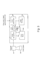
- FIG. 3 there is illustrated schematically logical components of the printing system shown in Fig. 1 in general overview, illustrating main process steps for carrying out a specific method according to the present invention.
- a color patch 300 is offered up to a scanner device 301 of the printer device.
- the scanner device scans the color patch, and color recognition algorithms within the scanner device output a color characterization signal.
- the scanner and color recognition algorithms 302 automatically measure the color, and a degree of accuracy of measurement is limited by the number of channels of the scanner.
- this information goes through a color map 306 to obtain device color co-ordinates along with a set of variations of those color co-ordinates.
- the variations of color co-ordinates are done in CIEL * a * b * , in three dimensions (3D).
- the variations can also be done in device color space, but this may be non trivial.
- a textile printer generally has between 7 and 12 colors, so sampling across this device color space is quite inefficient. Even to sample across a Cyan Magenta, Yellow, K (CMYK) four dimensional (4D) is quite complex if it is to be clear to a user. If three or less main colors are identified, e.g. Cyan Magenta Yellow, sampling is feasible. These may be specified by a user.
- Variation increments and directions may be decided either by a user or automatically.
- the variations are printed on the desired print media.
- the user must load the desired print media into the printer device, if it is not already loaded, so that the color variations can be printed directly onto the print media.
- a user Following printing of the spots onto the print media, a user must make a selection of color.
- the user can either select a color by determining an X, Y position in the array and entering this into the user interface on a printer device, or by simply marking the selected color spot with a different color ink.
- step 400 the user obtains a patch sample having the desired color and in step 401 scans the patch color using, in the best mode implementation, an internal scanner device of a printer.
- the scanner device recognizes the patch color in step 402, and prints an array of color spots onto a print medium in step 403.
- step 404 the user selects a printed color from the array of spot colors, and enters data describing the selected color into the printer device in step 405.
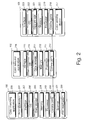
- a 9 x 9 array of spot colors printed into a print medium 500 there is illustrated schematically a 9 x 9 array of spot colors printed into a print medium 500.
- one of the spots is of a color corresponding to the color characterization signal input into the printer device as measured by the scanner device (or alternatively from the colorimeter/spectrophotometer).
- a range of colors are generated having locations in color space around the specified color of the color characterization signal.
- Each color spot is of a slightly different color to the target color 501 generated from the color characterization signal.
- each color shade within the array can be identified by its location within the array by an X and Y co-ordinate information. This is readily visible to the human user since an X, Y co-ordinate numbering system may be printed with the array. For example, the human user may select a color shade at position (2,4).
- a second array of color spots is identical to the first array of color spots, except a background coloration 600 is applied to the printer medium, allowing a user to make a visual judgement of the selected color, against a different background color from a base color of the print medium.
- the color of the background coloration 600 may be obtained by the same means as the targeted color spot, that is to say the background coloration may be scanned in as a color patch, or may be input by a user as a color characterization signal, from a colorimeter or spectrophotometer.
- Fig. 7 there is illustrated schematically process steps carried out by the printer device for scanning and selecting a color.
- Automatic steps are carried out by means of an algorithm stored as computer program instructions in a data storage device of the printer device.
- the instructions cause the data processor to operate the steps for controlling of the printer device for printing an array of colors, and for receiving input information via an interface or via the scanner for identifying a color of a printed array of colors, selected by a user.
- the color sample is scanned into the scanner by sensors 701.
- the sensors 701 can be part of the scanner device in the printer itself, or alternatively, an external colorimeter or spectrophotometer.
- step 702 the color sample is scanned with the external color sensor.
- scanning is carried out in step 703.
- the result of the scanning operation is a color characterization signal, comprising a CIEL * a * b * value 704.
- step 705 a set of CIEL * a * b * variations are generated for colors surrounding the input color in color space.
- step 706 the color map converts a CIEL * a * b * color co-ordinate to a device color space, for example CMYK.
- the color represented by the color characterization signal is mapped from its initial color space to a color space of the printer device.
- Variations of the color in the initial color space are computed in step 705, followed by mapping of each of those color variations to the device color space prior to printing.
- the device color space specifies which inks will be used for printing the finalised printed colors.
- the printer device prints a 2 dimensional array of color spots, where each color spot corresponds to an individual color variation generated in step 705, taking as its source data, data in the color map 706. This results in a printed document 708 on a print medium, showing an array of color spots, each having slightly different color, and centered around a target color, corresponding to the color characterization signal output from the external color sensor or printer scanner.
- a human user manually evaluates the color spots visually, and selects a color spot.
- the human user can then input details of the selected color spot in two ways. Firstly, the human user can visually read a two dimensional array position of the selected color spot and enter an X, Y co-ordinate value identifying that position within the array into a user interface of the printer device, or associated computer 102. Alternatively, the human user can simply mark the selected spot on the print medium with a different color ink, and the printer device may then automatically roll back the print medium under the scanner, scanning the array of color spots, to find a color spot which has been marked by the user in step 711.
- the printer device identifies, by an algorithm, which color spot has been selected from the array, and by identifying the two dimensional position in the array, can look up from a look up table, a corresponding color in the color map 706 which has been selected.
- the selection of the new color is stored in the printer device as a new color data.
- a human user visually selects a color spot.
- the human user reads the co-ordinates of the selected color spot, for example (2,4) and in step 802 enters those co-ordinates as X, Y co-ordinate into the printer device via the printer interface.
- the printer interface can be for example a keypad having digits 0-9 and an "enter" button, or can be a visual display presented on a browser of a PC 102, which browses a web display generated by the interface 207 of the printer device.
- step 900 the user inputs manually the two dimensional co-ordinates of a selected color in the two dimensional array which has been printed on the print medium.
- step 901 the scanner device scans in the co-ordinate of the selected color, and applies an algorithm to determine the two dimensional co-ordinates of the selected color as hereinbefore described.
- step 902 the printer device identifies the color at the selected two dimensional co-ordinate on the array from a three dimensional color map stored in the printer device's memory in step 706.
- the color selected in the color map corresponds to the two dimensional X, Y co-ordinate on the array of the color spot selected by the user.
- the printer device creates a new entry in a color book database, where the new entry corresponds to the selected color.
- Specific implementations according to the present invention may have an advantage of allowing sampling of a color patch by a printer device's own internal scanner, without the need for a colorimeter or spectrophotometer. This is both more convenient and less costly than using a colorimeter or spectrophotometer. Since an accurately matched color sampled from a color sample by the scanner or by a colorimeter/spectrophotometer may give a slightly different visual effect when printed on a print medium than expected, an opportunity is given for a human user to select a variation of the color from an automatically generated array of spot color variations having colors generated around the sampled color in color space. The user may select a particular color spot by marking that color spot or by noting the array position, and in the former case, the scanner device may automatically scan in and identify that selected color spot variation, and then store that information in an internal color block data stored on a printer device.
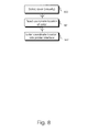
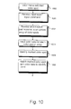
- Fig. 10 there is illustrated schematically process steps carried out by the printer device 100 for automatically identifying a color spot marked by a human user.
- the color spot is marked by the human user in step 1000 by the user applying a pen and circling, crossing or otherwise marking a selected color spot.
- the user activates the printer device to re-scan the color spot array containing the selected marked color spot, by inputting a "spot scan” command on an interface of the printer device.
- step 1002 in response to the input "spot scan” command, the printer device rewinds the print medium past the scanner head and the scanner head traverses across the array of color spots.
- step 1003 color data for each of the color spots in the array are input into the printer device, along with a set of relative two dimensional X, Y co-ordinate positions of those color spots.
- step 1004 the printer device identifies which particular color spot has been marked. This can occur for example by the printer device identifying a different color ink adjacent to one color spot, which does not fall within a set of colors initially printed for the color spots. Since the X, Y position of this outstanding color is known, this identifies the X, Y position of the color spot selected by the user.
- step 1005 having identified the selected color spot, the selected color spot is matched with the originally printed array of color spots, to make sure that the correct color spot has been identified, and following that check, the selected color can be input into the internal color book data, as described previously.
Abstract
Description
- The present invention relates to the field of printer devices, and particularly, although not exclusively to a method and apparatus for matching a user desired color onto a print medium.
- In the printing of images on a print media using a printer device, it is a common problem for a user of a printer device to emulate a color from a physical color patch supplied by a customer for print articles. For example, in the textile industry, textile designers may give samples to a human printer, operating a printer device, for the human printer to specify the colors for printing on a print material by a printer device. Finding an exact match of a physical color in a device color space is a non trivial exercise and has the following problems:
- Firstly, prior art solutions for color sensing require either a colorimeter or a spectrophotometer. Typically, these are stand alone devices which need to be connected to a printer. A color patch is placed in the colorimeter or spectrophotometer to measure the color, which is fed into the printer as a color specification in digital data. However, since the colorimeters or spectrophotometers are not integrated into a printer device and need to be connected, this makes the work flow more complex, and additionally they are expensive, in the range $250.00 to $10,000.00. However, depending upon the model and type of colorimeter or spectrophotometer used, these can be more accurate than in a built in color sensor provided with a printer device.
- Secondly, prior art automatic color matching systems may not fulfill the color matching expectation of an expert or a demanding designer. Small variations in shade may be very significant for some applications, particularly with spot colors. To obtain an acceptable color match solution, customers may be led into a time consuming and print media consuming iterative trial and error process for matching a color printed onto a print media with a sample color on a physical patch.
-
- One object of specific implementations according to the present invention is to reduce the time and print media usage in matching a color printed on a print media by a printer device, with an expected color, for example on a color patch.
- Another object of specific implementations according to the present invention is to achieve accurate color matching, without a requirement for a color sensing apparatus such as a colorimeter or spectrophotometer.
- Specific implementations according to the present invention aim to utilize a built in color sensor on a printer device to sense a color from a physical color patch or other color sample. A printer device provided with a scanner device is provided with functionality to select a range of colors close to the scanned in color and to print a set of color spots including the scanned in color and a plurality of color spots having colors close to the scanned in color on a print media. Preferably the print media is a print media specified by a customer or user, and to which a color is to be printed on to match the color patch.
- A user selects a color from a set of colors by visual inspection, and either enters a co-ordinate data into the printer device, identifying a position of the color within the set, or alternatively marks the color on the print medium which is then re-scanned by the scanner device of the printer, and an algorithm determines which color has been selected. The selected color is stored in a color book data within the printer device.
- According to a first aspect of the present invention there is provided a method of matching a printed color to a color sample, said method characterized by comprising the steps of:
- generating (702, 703, 704) a color characterization data from said color sample;
- generating (705) a plurality of variation color data corresponding to a plurality of variations of said color sample;
- printing (709) on a print medium said plurality of variations of said color;
- selecting (709, 710) an individual color of said plurality of variations of said color;
- inputting (710) a data describing a selected said individual color.
-
- According to a second aspect of the present invention there is provided a printer device capable of matching a printed color with a color sample, said printer device comprising:
- an interface (207, 303) capable of inputting color characterization data describing a color of said color sample;
- a printer mechanism (200) for printing color ink onto a print medium;
- a color generation component (303, 209) for generating a plurality of variation colors placed at positions in color space, around a position of a color specified by an input color characterization data; and
- a color book memory (209, 305) for storing data describing a selected said color.
-
- For a better understanding of the invention and to show how the same may be carried into effect, there will now be described by way of example only, specific embodiments, methods and processes according to the present invention with reference to the accompanying drawings in which:
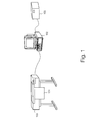
- Fig. 1 illustrates schematically a printer device capable of performing a spot color matching, according to a specific method of the present invention;
- Fig. 2 illustrates schematically individual components of the printing system of Fig. 1;
- Fig. 3 illustrates schematically components of the printing device of Fig. 1;
- Fig. 4 illustrates schematically a generalized method of operation of the printing system of Fig. 1;
- Fig. 5 illustrates schematically an array of color spots printed by a printer device on a print media according to a specific method of the present invention;
- Fig. 6 illustrates schematically an array of color spots printed by a printer device on a print media according to a specific method of the present invention, having a colored background;
- Fig. 7 illustrates schematically process steps carried out by the printer device for scanning and selecting a color to match a color patch or sample;
- Fig. 8 illustrates schematically a manual selection process for selecting and entering data describing a selected color spot;
- Fig. 9 illustrates schematically a process for creating a color book entry for a selected color spot; and
- Fig. 10 illustrates schematically a process for automatic selection of a color spot selected by a user.
-
- There will now be described by way of example the best mode contemplated by the inventors for carrying out the invention. In the following description numerous specific details are set forth in order to provide a thorough understanding of the present invention. It will be apparent however, to one skilled in the art, that the present invention may be practiced without limitation to these specific details. In other instances, well known methods and structures have not been described in detail so as not to unnecessarily obscure the present invention.
- Referring to Fig. 1 herein, there is illustrated schematically apparatus according to a specific embodiment of the present invention, comprising a
printer device 100 for printing a poster orother print material 101 with color inks; a computer, for example apersonal computer 102 communicating with theprinter device 100; and optionally, a color sensing device such as a colorimeter, orspectrophotometer 103 may be provided. - Referring to Fig. 2 herein, there is illustrated schematically components of the apparatus of Fig. 1.
Printer 100 comprises aprinter mechanism 200 for printing color inks onto a print medium; ascanner device 201 for scanning a color sample, e.g. a color patch, to produce a color signal representing a shade of color of the color sample; acommunications port 202 for communicating with other computer entities; adata processor 203; avolatile memory device 204; adata storage device 205, for example a hard disk drive; anoperating system 206; aninterface 207 for enabling an operator to input instructions to the printer device, and obtain a visual display of operations carried out by the printer device, aprint application 208 for managing print of images by theprinter mechanism 200; and acolor matching application 209 for receiving color data from saidcolor scanner 201 and/or an external source and/orinterface 207, and generating a range of color signals for printing a corresponding respective range of colors via theprinter mechanism 200 on a print medium. -
Computer entity 102 comprises acommunications port 210 for communicating with the printer device; adata processor 211; a nonvolatile memory device 212; adata storage device 213, for example a hard disk data storage device; anoperating system 214; an interface 215 comprising a visual display monitor, keyboard and printing device; and a color selection application 215. - The color sensing device, for example a colorimeter or spectrophotometer may comprise a
color sensor 217 for sensing a color of a color patch or other sample having color; acommunications port 218 for communicating with other entities; adata processor 219; avolatile memory device 220; adata storage device 221, for example a hard disk drive or similar; anoperating system 222; and aninterface 223 for enabling a user to enter instructions for operating the color sensing device, and receiving visually displayed information concerning the operation of the color sensing device. - Whilst Figs. 1 and 2 illustrate a specific embodiment according to the present invention, variations on implementation can be made without departing from the scope of the invention. For example, the
interface 207 on the printer device may comprise a web administration interface accessible via the communications port of that printer device, over a communications network, and be readable by a web browser resident oncomputer entity 102, via which an operator may use to remotely instruct and monitor the printer device. Further, the color matchingapplication 209 may be resident on the printer device itself, or resident on aseparate computer entity 102. The functionality of the color matching application to select a range of colors may be independent of its physical location, or a physical platform on which the application is installed. However, in the best mode herein the color matchingapplication 209 is resident on the printer device. - Further,
color sensing device 103 may be utilized to provide an output of sensed color data, which may be input into the printer device, via thecommunications port 202, aninterface 207 of the printer device, either directly or via an intermediate computer entity, for example thecomputer entity 102 as an alternative to scanning in a color sample using thescanner 201 on the printer device. Thecolor sensing device 103 is an optional feature, and may provide a higher accuracy color match to a color patch or color sample, than ascanner device 201 of the printer device. However, in its broadest scope of the invention, thecolor sensing device 103 in the form of a colorimeter or spectrophotometer, is not essential, and in the best mode implementation is not present. - Referring to Fig. 3 herein, there is illustrated schematically logical components of the printing system shown in Fig. 1 in general overview, illustrating main process steps for carrying out a specific method according to the present invention. A
color patch 300 is offered up to ascanner device 301 of the printer device. The scanner device scans the color patch, and color recognition algorithms within the scanner device output a color characterization signal. The scanner andcolor recognition algorithms 302 automatically measure the color, and a degree of accuracy of measurement is limited by the number of channels of the scanner. - Once the color is characterized, for example CIEL*a*b*, data is obtained, this information goes through a
color map 306 to obtain device color co-ordinates along with a set of variations of those color co-ordinates. The variations of color co-ordinates are done in CIEL*a*b*, in three dimensions (3D). The variations can also be done in device color space, but this may be non trivial. A textile printer generally has between 7 and 12 colors, so sampling across this device color space is quite inefficient. Even to sample across a Cyan Magenta, Yellow, K (CMYK) four dimensional (4D) is quite complex if it is to be clear to a user. If three or less main colors are identified, e.g. Cyan Magenta Yellow, sampling is feasible. These may be specified by a user. - Variation increments and directions may be decided either by a user or automatically.
- After
color generation 303, the variations are printed on the desired print media. The user must load the desired print media into the printer device, if it is not already loaded, so that the color variations can be printed directly onto the print media. - Following printing of the spots onto the print media, a user must make a selection of color. The user can either select a color by determining an X, Y position in the array and entering this into the user interface on a printer device, or by simply marking the selected color spot with a different color ink.
- Referring to Fig. 4 herein, in
step 400, the user obtains a patch sample having the desired color and instep 401 scans the patch color using, in the best mode implementation, an internal scanner device of a printer. The scanner device recognizes the patch color instep 402, and prints an array of color spots onto a print medium instep 403. Instep 404, the user selects a printed color from the array of spot colors, and enters data describing the selected color into the printer device instep 405. - Referring to Fig. 5 herein, there is illustrated schematically a 9 x 9 array of spot colors printed into a
print medium 500. Within the array, one of the spots is of a color corresponding to the color characterization signal input into the printer device as measured by the scanner device (or alternatively from the colorimeter/spectrophotometer). A range of colors are generated having locations in color space around the specified color of the color characterization signal. Each color spot is of a slightly different color to thetarget color 501 generated from the color characterization signal. Additionally, each color shade within the array can be identified by its location within the array by an X and Y co-ordinate information. This is readily visible to the human user since an X, Y co-ordinate numbering system may be printed with the array. For example, the human user may select a color shade at position (2,4). - Referring to Fig. 6 herein, there is illustrated schematically a second array of color spots. The second array of color spots is identical to the first array of color spots, except a
background coloration 600 is applied to the printer medium, allowing a user to make a visual judgement of the selected color, against a different background color from a base color of the print medium. The color of thebackground coloration 600 may be obtained by the same means as the targeted color spot, that is to say the background coloration may be scanned in as a color patch, or may be input by a user as a color characterization signal, from a colorimeter or spectrophotometer. - Referring to Fig. 7 herein, there is illustrated schematically process steps carried out by the printer device for scanning and selecting a color. Automatic steps are carried out by means of an algorithm stored as computer program instructions in a data storage device of the printer device. The instructions cause the data processor to operate the steps for controlling of the printer device for printing an array of colors, and for receiving input information via an interface or via the scanner for identifying a color of a printed array of colors, selected by a user. In
step 700, the color sample is scanned into the scanner bysensors 701. Thesensors 701 can be part of the scanner device in the printer itself, or alternatively, an external colorimeter or spectrophotometer. In the case of an external colorimeter or spectrophotometer, instep 702 the color sample is scanned with the external color sensor. In the case of the internal scanner of the printer, scanning is carried out instep 703. The result of the scanning operation is a color characterization signal, comprising a CIEL*a*b* value 704. Instep 705, a set of CIEL*a*b* variations are generated for colors surrounding the input color in color space. Instep 706, the color map converts a CIEL*a*b* color co-ordinate to a device color space, for example CMYK. The color represented by the color characterization signal is mapped from its initial color space to a color space of the printer device. Variations of the color in the initial color space (CIEL*a*b*) are computed instep 705, followed by mapping of each of those color variations to the device color space prior to printing. The device color space specifies which inks will be used for printing the finalised printed colors. Instep 707, the printer device prints a 2 dimensional array of color spots, where each color spot corresponds to an individual color variation generated instep 705, taking as its source data, data in thecolor map 706. This results in a printeddocument 708 on a print medium, showing an array of color spots, each having slightly different color, and centered around a target color, corresponding to the color characterization signal output from the external color sensor or printer scanner. In step 709 a human user manually evaluates the color spots visually, and selects a color spot. The human user can then input details of the selected color spot in two ways. Firstly, the human user can visually read a two dimensional array position of the selected color spot and enter an X, Y co-ordinate value identifying that position within the array into a user interface of the printer device, or associatedcomputer 102. Alternatively, the human user can simply mark the selected spot on the print medium with a different color ink, and the printer device may then automatically roll back the print medium under the scanner, scanning the array of color spots, to find a color spot which has been marked by the user instep 711. During the automatic position identification scanning, the printer device identifies, by an algorithm, which color spot has been selected from the array, and by identifying the two dimensional position in the array, can look up from a look up table, a corresponding color in thecolor map 706 which has been selected. Instep 713, the selection of the new color is stored in the printer device as a new color data. - Referring to Fig. 8 herein, there is illustrated schematically process steps carried out for manual selection of a color spot from a printed array of color spots. In
step 800, having viewed an array of color spots, a human user visually selects a color spot. Instep 801, the human user reads the co-ordinates of the selected color spot, for example (2,4) and instep 802 enters those co-ordinates as X, Y co-ordinate into the printer device via the printer interface. The printer interface can be for example a keypad having digits 0-9 and an "enter" button, or can be a visual display presented on a browser of aPC 102, which browses a web display generated by theinterface 207 of the printer device. - Referring to Fig. 9 herein, there is illustrated schematically process steps carried out by the printer device for creating a new entry in a color book corresponding to a selected color. In
step 900 the user inputs manually the two dimensional co-ordinates of a selected color in the two dimensional array which has been printed on the print medium. Alternatively, instep 901, the scanner device scans in the co-ordinate of the selected color, and applies an algorithm to determine the two dimensional co-ordinates of the selected color as hereinbefore described. Instep 902, the printer device identifies the color at the selected two dimensional co-ordinate on the array from a three dimensional color map stored in the printer device's memory instep 706. The color selected in the color map corresponds to the two dimensional X, Y co-ordinate on the array of the color spot selected by the user. Instep 903, the printer device creates a new entry in a color book database, where the new entry corresponds to the selected color. - Specific implementations according to the present invention may have an advantage of allowing sampling of a color patch by a printer device's own internal scanner, without the need for a colorimeter or spectrophotometer. This is both more convenient and less costly than using a colorimeter or spectrophotometer. Since an accurately matched color sampled from a color sample by the scanner or by a colorimeter/spectrophotometer may give a slightly different visual effect when printed on a print medium than expected, an opportunity is given for a human user to select a variation of the color from an automatically generated array of spot color variations having colors generated around the sampled color in color space. The user may select a particular color spot by marking that color spot or by noting the array position, and in the former case, the scanner device may automatically scan in and identify that selected color spot variation, and then store that information in an internal color block data stored on a printer device.
- Referring to Fig. 10 herein, there is illustrated schematically process steps carried out by the
printer device 100 for automatically identifying a color spot marked by a human user. The color spot is marked by the human user instep 1000 by the user applying a pen and circling, crossing or otherwise marking a selected color spot. Instep 1001 the user activates the printer device to re-scan the color spot array containing the selected marked color spot, by inputting a "spot scan" command on an interface of the printer device. Instep 1002, in response to the input "spot scan" command, the printer device rewinds the print medium past the scanner head and the scanner head traverses across the array of color spots. Instep 1003, color data for each of the color spots in the array are input into the printer device, along with a set of relative two dimensional X, Y co-ordinate positions of those color spots. Instep 1004, the printer device identifies which particular color spot has been marked. This can occur for example by the printer device identifying a different color ink adjacent to one color spot, which does not fall within a set of colors initially printed for the color spots. Since the X, Y position of this outstanding color is known, this identifies the X, Y position of the color spot selected by the user. Instep 1005, having identified the selected color spot, the selected color spot is matched with the originally printed array of color spots, to make sure that the correct color spot has been identified, and following that check, the selected color can be input into the internal color book data, as described previously.
Claims (16)
- A method of matching a printed color to a color sample, said method characterized by comprising the steps of:generating (702, 703, 704) a color characterization data from said color sample;generating (705) a plurality of variation color data corresponding to a plurality of variations of said color sample;printing (709) on a print medium said plurality of variations of said color;selecting (709, 710) an individual color of said plurality of variations of said color; andinputting (710) a data describing a selected said individual color.
- The method as claimed in claim 1 further comprising the step of:storing (713) said selected individual color in a color book data.
- The method as claimed in claim 1 or 2, wherein said step of generating a color characterization data from said color sample comprises:offering a color sample to a scanner device, and said scanner device generating said color characterization data.
- The method as claimed in any one of claims 1 to 3, wherein said step of generating a plurality of variation color data comprises:generating a plurality of variation colors corresponding to colors at co-ordinates in color space around said color characterization data.
- The method as claimed in any one of the preceding claims, wherein said step of printing said plurality of variations of said color comprises:printing a plurality of colors in a two dimensional array on a print medium, said plurality of colors corresponding to a plurality of color co-ordinates around said color characterization signal in color space.
- The method as claimed in any one of the preceding claims, wherein said step of selecting an individual color comprises:marking a selected color spot by means of applying a different color ink on or near said color spot; andinspection of an array of printed said color variations on a print medium.
- The method as claimed in any one of the preceding claims, wherein said step of inputting a data describing a selected color variation comprises:determining a data identifying a selected color spot;inputting said data identifying said selected color spot, into a printer device.
- The method as claimed in claim 7, comprising:scanning an array of printed color spots, each said color spot corresponding to a color variation in color space around said color characterization data to obtain a scanned color spot data; andfrom said scanned in color spot data, identifying a selected color spot as being a color spot physically marked to distinguish it from other said color spots of said array.
- The method as claimed in claim 7, further comprising the step of:matching said identification data with a color characterization data of said selected color.
- A printer device capable of matching a printed color with a color sample, said printer device comprising:an interface (207, 303) capable of inputting color characterization data describing a color of said color sample;a printer mechanism (200) for printing color ink onto a print medium;a color generation component (303, 209) for generating a plurality of variation colors placed at positions in color space, around a position of a color specified by an input color characterization data; anda color book memory (209, 305) for storing data describing a selected said color.
- The printer device as claimed in claim 8, comprising:a scanner device (201, 301) for scanning at least one color from said color sample, wherein said scanner device is configured to scan in a color of a color sample and generate a color sample characterization data.
- The printer device as claimed in claim 10 or 11, further comprising a scanning (201, 301) device arranged to scan in at least one color data, wherein:said scanner operates to scan an array of color spots, corresponding to a plurality of color variations occupying positions in color space around a color space location corresponding to said sample color.
- The printer device as claimed in any one of claims 10 to 12, comprising:an interface (207) capable of receiving color characterization data from a color sensor device (103).
- The printer device as claimed in any one of claims 10 to 12, comprising a scanning algorithm, said scanning algorithm operating to:scan a two dimensional array of color spots printed onto a print medium;recognize an individual said color spot selected by a user; andstore a color characterization data corresponding to said recognized selected color spot.
- The printer device as claimed in any one of claims 10 to 14, operable to:recognize a position of a said input color characterization data in three dimensional color space;generate a plurality of variation color data in said three dimensional color space, said variation color characterization data generated at positions in said three dimensional data space around said input color characterization data;print a plurality of color spots, corresponding to said plurality of generated variation color characterization data, in a two dimensional format on a print medium.
- The printer device as claimed in claim 15, further operable to:print a plurality of identification data for identifying individual color spots within said printed two dimensional array on said print medium.
Priority Applications (4)
| Application Number | Priority Date | Filing Date | Title |
|---|---|---|---|
| EP01306082A EP1276314B1 (en) | 2001-07-13 | 2001-07-13 | Spot color application in printer device |
| DE60131385T DE60131385T2 (en) | 2001-07-13 | 2001-07-13 | Using single colors with a printer |
| JP2002198333A JP2003134349A (en) | 2001-07-13 | 2002-07-08 | Application of spot color in printer |
| US10/194,957 US7239402B2 (en) | 2001-07-13 | 2002-07-11 | Spot color application in printer device |
Applications Claiming Priority (1)
| Application Number | Priority Date | Filing Date | Title |
|---|---|---|---|
| EP01306082A EP1276314B1 (en) | 2001-07-13 | 2001-07-13 | Spot color application in printer device |
Publications (2)
| Publication Number | Publication Date |
|---|---|
| EP1276314A1 true EP1276314A1 (en) | 2003-01-15 |
| EP1276314B1 EP1276314B1 (en) | 2007-11-14 |
Family
ID=8182106
Family Applications (1)
| Application Number | Title | Priority Date | Filing Date |
|---|---|---|---|
| EP01306082A Expired - Lifetime EP1276314B1 (en) | 2001-07-13 | 2001-07-13 | Spot color application in printer device |
Country Status (4)
| Country | Link |
|---|---|
| US (1) | US7239402B2 (en) |
| EP (1) | EP1276314B1 (en) |
| JP (1) | JP2003134349A (en) |
| DE (1) | DE60131385T2 (en) |
Cited By (4)
| Publication number | Priority date | Publication date | Assignee | Title |
|---|---|---|---|---|
| EP1594303A1 (en) * | 2004-05-05 | 2005-11-09 | GretagMacbeth AG | Method for optimizing a digital document containing spot colors |
| GB2495600A (en) * | 2011-10-05 | 2013-04-17 | Xerox Corp | Spot colour editing assistant tool for spot colour reproduction |
| EP2437482A3 (en) * | 2010-09-30 | 2013-10-30 | FUJIFILM Corporation | Color value acquiring method, image processing method, color value acquiring apparatus, image processing apparatus, and recording medium |
| EP2933994A1 (en) * | 2014-04-15 | 2015-10-21 | Seiko Epson Corporation | Color adjustment method, and printing pattern for color adjustment |
Families Citing this family (50)
| Publication number | Priority date | Publication date | Assignee | Title |
|---|---|---|---|---|
| JP3820979B2 (en) * | 2001-12-17 | 2006-09-13 | ブラザー工業株式会社 | Patch forming apparatus and program |
| JP4307095B2 (en) * | 2003-02-05 | 2009-08-05 | キヤノン株式会社 | Color conversion method and profile creation method |
| JP2005210208A (en) | 2004-01-20 | 2005-08-04 | Fuji Xerox Co Ltd | Image processor, image processing method, and program |
| DE102004009271A1 (en) * | 2004-02-26 | 2005-09-15 | Man Roland Druckmaschinen Ag | Method for color control on printing machines |
| JP4401955B2 (en) * | 2004-03-03 | 2010-01-20 | キヤノン株式会社 | Color processing apparatus and method |
| US7970171B2 (en) | 2007-01-18 | 2011-06-28 | Ricoh Co., Ltd. | Synthetic image and video generation from ground truth data |
| US8868555B2 (en) | 2006-07-31 | 2014-10-21 | Ricoh Co., Ltd. | Computation of a recongnizability score (quality predictor) for image retrieval |
| US8949287B2 (en) | 2005-08-23 | 2015-02-03 | Ricoh Co., Ltd. | Embedding hot spots in imaged documents |
| US9530050B1 (en) | 2007-07-11 | 2016-12-27 | Ricoh Co., Ltd. | Document annotation sharing |
| US8335789B2 (en) * | 2004-10-01 | 2012-12-18 | Ricoh Co., Ltd. | Method and system for document fingerprint matching in a mixed media environment |
| US8510283B2 (en) | 2006-07-31 | 2013-08-13 | Ricoh Co., Ltd. | Automatic adaption of an image recognition system to image capture devices |
| US8156116B2 (en) | 2006-07-31 | 2012-04-10 | Ricoh Co., Ltd | Dynamic presentation of targeted information in a mixed media reality recognition system |
| US9171202B2 (en) | 2005-08-23 | 2015-10-27 | Ricoh Co., Ltd. | Data organization and access for mixed media document system |
| US8825682B2 (en) | 2006-07-31 | 2014-09-02 | Ricoh Co., Ltd. | Architecture for mixed media reality retrieval of locations and registration of images |
| US8332401B2 (en) | 2004-10-01 | 2012-12-11 | Ricoh Co., Ltd | Method and system for position-based image matching in a mixed media environment |
| US8176054B2 (en) | 2007-07-12 | 2012-05-08 | Ricoh Co. Ltd | Retrieving electronic documents by converting them to synthetic text |
| US8600989B2 (en) | 2004-10-01 | 2013-12-03 | Ricoh Co., Ltd. | Method and system for image matching in a mixed media environment |
| US9405751B2 (en) | 2005-08-23 | 2016-08-02 | Ricoh Co., Ltd. | Database for mixed media document system |
| US8369655B2 (en) | 2006-07-31 | 2013-02-05 | Ricoh Co., Ltd. | Mixed media reality recognition using multiple specialized indexes |
| US9384619B2 (en) | 2006-07-31 | 2016-07-05 | Ricoh Co., Ltd. | Searching media content for objects specified using identifiers |
| US10192279B1 (en) | 2007-07-11 | 2019-01-29 | Ricoh Co., Ltd. | Indexed document modification sharing with mixed media reality |
| US7702673B2 (en) | 2004-10-01 | 2010-04-20 | Ricoh Co., Ltd. | System and methods for creation and use of a mixed media environment |
| US9373029B2 (en) | 2007-07-11 | 2016-06-21 | Ricoh Co., Ltd. | Invisible junction feature recognition for document security or annotation |
| US8276088B2 (en) * | 2007-07-11 | 2012-09-25 | Ricoh Co., Ltd. | User interface for three-dimensional navigation |
| US8385589B2 (en) | 2008-05-15 | 2013-02-26 | Berna Erol | Web-based content detection in images, extraction and recognition |
| US8838591B2 (en) | 2005-08-23 | 2014-09-16 | Ricoh Co., Ltd. | Embedding hot spots in electronic documents |
| US8521737B2 (en) | 2004-10-01 | 2013-08-27 | Ricoh Co., Ltd. | Method and system for multi-tier image matching in a mixed media environment |
| US8856108B2 (en) | 2006-07-31 | 2014-10-07 | Ricoh Co., Ltd. | Combining results of image retrieval processes |
| US7847986B2 (en) * | 2005-03-31 | 2010-12-07 | Microsoft Corporation | Multiband color management |
| US9020966B2 (en) | 2006-07-31 | 2015-04-28 | Ricoh Co., Ltd. | Client device for interacting with a mixed media reality recognition system |
| US8676810B2 (en) | 2006-07-31 | 2014-03-18 | Ricoh Co., Ltd. | Multiple index mixed media reality recognition using unequal priority indexes |
| US9063952B2 (en) | 2006-07-31 | 2015-06-23 | Ricoh Co., Ltd. | Mixed media reality recognition with image tracking |
| US8489987B2 (en) | 2006-07-31 | 2013-07-16 | Ricoh Co., Ltd. | Monitoring and analyzing creation and usage of visual content using image and hotspot interaction |
| US9176984B2 (en) | 2006-07-31 | 2015-11-03 | Ricoh Co., Ltd | Mixed media reality retrieval of differentially-weighted links |
| JP4983509B2 (en) * | 2007-09-26 | 2012-07-25 | 富士ゼロックス株式会社 | Image processing apparatus, image forming apparatus, and program |
| US8385660B2 (en) | 2009-06-24 | 2013-02-26 | Ricoh Co., Ltd. | Mixed media reality indexing and retrieval for repeated content |
| JP5479837B2 (en) * | 2009-09-30 | 2014-04-23 | 富士フイルム株式会社 | Color selection method, image processing method, and image processing apparatus |
| JP5508993B2 (en) | 2010-08-31 | 2014-06-04 | 富士フイルム株式会社 | Color value acquisition method, image processing method, color value acquisition device, image processing device, and color value acquisition program |
| JP5462756B2 (en) * | 2010-09-27 | 2014-04-02 | 富士フイルム株式会社 | Color selection support method, color value acquisition method, image processing method, color selection support device, color value acquisition device, image processing device, and program |
| JP5436388B2 (en) * | 2010-10-05 | 2014-03-05 | キヤノン株式会社 | Image processing apparatus, image processing method, and image recording apparatus |
| JP5541721B2 (en) * | 2010-10-05 | 2014-07-09 | キヤノン株式会社 | Image processing apparatus and image processing method |
| JP5465145B2 (en) * | 2010-10-05 | 2014-04-09 | キヤノン株式会社 | Image processing apparatus, image processing method, and image recording apparatus |
| US9058331B2 (en) | 2011-07-27 | 2015-06-16 | Ricoh Co., Ltd. | Generating a conversation in a social network based on visual search results |
| WO2013100895A1 (en) | 2011-12-27 | 2013-07-04 | Hewlett-Packard Development Company, L.P. | Press color state estimator |
| JP5784159B2 (en) * | 2014-01-23 | 2015-09-24 | キヤノン株式会社 | Image processing apparatus, image recording apparatus, and image processing method |
| JP5706979B2 (en) * | 2014-02-13 | 2015-04-22 | 富士フイルム株式会社 | Printing data generation method, apparatus and program, and color chart |
| US10341535B2 (en) | 2015-01-30 | 2019-07-02 | Hewlett-Packard Development Company, L.P. | Color calibration |
| WO2019048029A1 (en) | 2017-09-05 | 2019-03-14 | Hp Indigo B.V. | Method and printer system for determining adjusted output settings |
| WO2020222825A1 (en) | 2019-04-30 | 2020-11-05 | Hewlett-Packard Development Company, L.P. | Modular and tiled optical sensors |
| JP2021093719A (en) * | 2019-12-09 | 2021-06-17 | キヤノン株式会社 | Image processing apparatus, image processing method, and program |
Citations (6)
| Publication number | Priority date | Publication date | Assignee | Title |
|---|---|---|---|---|
| US4979031A (en) * | 1988-07-12 | 1990-12-18 | Minolta Camera Kabushiki Kaisha | Digital color copying machine |
| EP0854638A2 (en) * | 1997-01-21 | 1998-07-22 | Xerox Corporation | A method for continuous incremental color calibration for color document output terminals |
| US5809366A (en) * | 1995-03-24 | 1998-09-15 | Ricoh Company, Ltd. | Method and system for calibrating a color copier |
| US5973801A (en) * | 1995-08-21 | 1999-10-26 | Scitex Corp., Ltd. | Method for matching colors of an object to printing colors |
| US5987166A (en) * | 1994-10-28 | 1999-11-16 | Canon Kabushiki Kaisha | Image processing apparatus capable of marker editing original image |
| US6008907A (en) * | 1997-10-15 | 1999-12-28 | Polaroid Corporation | Printer calibration |
Family Cites Families (9)
| Publication number | Priority date | Publication date | Assignee | Title |
|---|---|---|---|---|
| JP3618889B2 (en) * | 1996-04-02 | 2005-02-09 | キヤノン株式会社 | Image processing apparatus and method |
| JP3890132B2 (en) * | 1997-01-31 | 2007-03-07 | キヤノン株式会社 | Network server and image processing method |
| US6480299B1 (en) * | 1997-11-25 | 2002-11-12 | University Technology Corporation | Color printer characterization using optimization theory and neural networks |
| US6456395B1 (en) * | 1999-08-30 | 2002-09-24 | Microsoft Corporation | Method for separating colors of encapsulated postscript images |
| DE60015675T3 (en) * | 1999-09-06 | 2010-01-14 | Komori Corporation | Color management method and apparatus for a printing press |
| US6833937B1 (en) * | 2000-01-21 | 2004-12-21 | Lexmark International, Inc. | Methods and apparatus for color mapping |
| US6924908B1 (en) * | 2000-05-31 | 2005-08-02 | Brown University Research Foundation | Color management systems and methods with improved color matching techniques |
| JP4038998B2 (en) * | 2001-02-23 | 2008-01-30 | セイコーエプソン株式会社 | Printing with reduced color light source dependency |
| US7009733B2 (en) * | 2001-07-02 | 2006-03-07 | Coral Corporation | Manual correction of an image color |
-
2001
- 2001-07-13 DE DE60131385T patent/DE60131385T2/en not_active Expired - Lifetime
- 2001-07-13 EP EP01306082A patent/EP1276314B1/en not_active Expired - Lifetime
-
2002
- 2002-07-08 JP JP2002198333A patent/JP2003134349A/en active Pending
- 2002-07-11 US US10/194,957 patent/US7239402B2/en active Active
Patent Citations (6)
| Publication number | Priority date | Publication date | Assignee | Title |
|---|---|---|---|---|
| US4979031A (en) * | 1988-07-12 | 1990-12-18 | Minolta Camera Kabushiki Kaisha | Digital color copying machine |
| US5987166A (en) * | 1994-10-28 | 1999-11-16 | Canon Kabushiki Kaisha | Image processing apparatus capable of marker editing original image |
| US5809366A (en) * | 1995-03-24 | 1998-09-15 | Ricoh Company, Ltd. | Method and system for calibrating a color copier |
| US5973801A (en) * | 1995-08-21 | 1999-10-26 | Scitex Corp., Ltd. | Method for matching colors of an object to printing colors |
| EP0854638A2 (en) * | 1997-01-21 | 1998-07-22 | Xerox Corporation | A method for continuous incremental color calibration for color document output terminals |
| US6008907A (en) * | 1997-10-15 | 1999-12-28 | Polaroid Corporation | Printer calibration |
Cited By (4)
| Publication number | Priority date | Publication date | Assignee | Title |
|---|---|---|---|---|
| EP1594303A1 (en) * | 2004-05-05 | 2005-11-09 | GretagMacbeth AG | Method for optimizing a digital document containing spot colors |
| EP2437482A3 (en) * | 2010-09-30 | 2013-10-30 | FUJIFILM Corporation | Color value acquiring method, image processing method, color value acquiring apparatus, image processing apparatus, and recording medium |
| GB2495600A (en) * | 2011-10-05 | 2013-04-17 | Xerox Corp | Spot colour editing assistant tool for spot colour reproduction |
| EP2933994A1 (en) * | 2014-04-15 | 2015-10-21 | Seiko Epson Corporation | Color adjustment method, and printing pattern for color adjustment |
Also Published As
| Publication number | Publication date |
|---|---|
| DE60131385T2 (en) | 2008-06-19 |
| DE60131385D1 (en) | 2007-12-27 |
| EP1276314B1 (en) | 2007-11-14 |
| US20030030828A1 (en) | 2003-02-13 |
| US7239402B2 (en) | 2007-07-03 |
| JP2003134349A (en) | 2003-05-09 |
Similar Documents
| Publication | Publication Date | Title |
|---|---|---|
| US7239402B2 (en) | Spot color application in printer device | |
| JP5462756B2 (en) | Color selection support method, color value acquisition method, image processing method, color selection support device, color value acquisition device, image processing device, and program | |
| US20040078299A1 (en) | Portable color and style analysis, match and management system | |
| JP4074715B2 (en) | Determining the optimal color space direction for selecting color modulation | |
| US6809837B1 (en) | On-line model prediction and calibration system for a dynamically varying color reproduction device | |
| JP5508975B2 (en) | Color selection method, image processing method, image processing apparatus, and program | |
| US7031550B2 (en) | Image processing method of generating conversion data for a scanner and calibration method employing the scanner | |
| JP4047684B2 (en) | Method for measuring color calibration pattern and performing corrective action | |
| JP6416750B2 (en) | Measuring apparatus, measuring method, information processing apparatus and measuring program | |
| EP1001610A2 (en) | Model-based spectral calibration of color scanners | |
| JP2002268864A (en) | Accurate printing of proprietary mark pattern and color | |
| CN100522631C (en) | Display apparatus and display method | |
| JP4381313B2 (en) | Correction of colorimetric values measured under different observation conditions | |
| EP1310376A2 (en) | Simplified tone scale correction | |
| JP6506601B2 (en) | Recording device, judgment method | |
| JP2008232665A (en) | Pressure analysis system | |
| JP3879310B2 (en) | Gradation characteristic data creation system and recording medium on which gradation characteristic data creation processing program is recorded | |
| Tse et al. | Automated print quality analysis for digital printing technologies | |
| JP5610687B2 (en) | Information processing apparatus, method, and program | |
| KR100609062B1 (en) | System for ordering textile by using internet and method for ordering thereof | |
| JPH10305562A (en) | System for evaluating printed matter | |
| CN109870236A (en) | Colour examining position prompting system and colour examining position indicating method | |
| JP3915437B2 (en) | Apparatus and method for creating color reproduction characteristic data using communication line | |
| JP2001004448A (en) | Colorimetric device using scanner | |
| CN117632050A (en) | Information processing apparatus, information processing method, and information processing system |
Legal Events
| Date | Code | Title | Description |
|---|---|---|---|
| PUAI | Public reference made under article 153(3) epc to a published international application that has entered the european phase |
Free format text: ORIGINAL CODE: 0009012 |
|
| AK | Designated contracting states |
Kind code of ref document: A1 Designated state(s): AT BE CH CY DE DK ES FI FR GB GR IE IT LI LU MC NL PT SE TR |
|
| AX | Request for extension of the european patent |
Free format text: AL;LT;LV;MK;RO;SI |
|
| 17P | Request for examination filed |
Effective date: 20030715 |
|
| AKX | Designation fees paid |
Designated state(s): DE ES FR GB IT |
|
| 17Q | First examination report despatched |
Effective date: 20050629 |
|
| GRAP | Despatch of communication of intention to grant a patent |
Free format text: ORIGINAL CODE: EPIDOSNIGR1 |
|
| GRAC | Information related to communication of intention to grant a patent modified |
Free format text: ORIGINAL CODE: EPIDOSCIGR1 |
|
| GRAS | Grant fee paid |
Free format text: ORIGINAL CODE: EPIDOSNIGR3 |
|
| GRAA | (expected) grant |
Free format text: ORIGINAL CODE: 0009210 |
|
| AK | Designated contracting states |
Kind code of ref document: B1 Designated state(s): DE ES FR GB IT |
|
| REG | Reference to a national code |
Ref country code: GB Ref legal event code: FG4D |
|
| REF | Corresponds to: |
Ref document number: 60131385 Country of ref document: DE Date of ref document: 20071227 Kind code of ref document: P |
|
| PG25 | Lapsed in a contracting state [announced via postgrant information from national office to epo] |
Ref country code: ES Free format text: LAPSE BECAUSE OF FAILURE TO SUBMIT A TRANSLATION OF THE DESCRIPTION OR TO PAY THE FEE WITHIN THE PRESCRIBED TIME-LIMIT Effective date: 20080225 |
|
| EN | Fr: translation not filed | ||
| PLBE | No opposition filed within time limit |
Free format text: ORIGINAL CODE: 0009261 |
|
| STAA | Information on the status of an ep patent application or granted ep patent |
Free format text: STATUS: NO OPPOSITION FILED WITHIN TIME LIMIT |
|
| 26N | No opposition filed |
Effective date: 20080815 |
|
| PG25 | Lapsed in a contracting state [announced via postgrant information from national office to epo] |
Ref country code: FR Free format text: LAPSE BECAUSE OF FAILURE TO SUBMIT A TRANSLATION OF THE DESCRIPTION OR TO PAY THE FEE WITHIN THE PRESCRIBED TIME-LIMIT Effective date: 20080829 |
|
| PG25 | Lapsed in a contracting state [announced via postgrant information from national office to epo] |
Ref country code: IT Free format text: LAPSE BECAUSE OF NON-PAYMENT OF DUE FEES Effective date: 20080731 |
|
| REG | Reference to a national code |
Ref country code: GB Ref legal event code: 732E Free format text: REGISTERED BETWEEN 20120329 AND 20120404 |
|
| PGFP | Annual fee paid to national office [announced via postgrant information from national office to epo] |
Ref country code: GB Payment date: 20170620 Year of fee payment: 17 |
|
| PGFP | Annual fee paid to national office [announced via postgrant information from national office to epo] |
Ref country code: DE Payment date: 20170620 Year of fee payment: 17 |
|
| REG | Reference to a national code |
Ref country code: DE Ref legal event code: R119 Ref document number: 60131385 Country of ref document: DE |
|
| GBPC | Gb: european patent ceased through non-payment of renewal fee |
Effective date: 20180713 |
|
| PG25 | Lapsed in a contracting state [announced via postgrant information from national office to epo] |
Ref country code: DE Free format text: LAPSE BECAUSE OF NON-PAYMENT OF DUE FEES Effective date: 20190201 Ref country code: GB Free format text: LAPSE BECAUSE OF NON-PAYMENT OF DUE FEES Effective date: 20180713 |