Technical Field of the Invention
This invention relates to the electrophoretic separation, purification and
recovery of compounds from solution.
Background Art
Complex mixtures such as biological samples can contain up to 30,000 different
proteins which need to be separated and identified for further analysis. In proteome
analysis, high resolution separation of complex protein mixtures requires the development
of novel techniques which minimize separation times, are easy to use, result in a high
degree of purity and allow for further analysis of the compound(s) of interest extracted from
the sample without unnecessary additional purification steps.
2D-gel electrophoresis is one technique which is capable of separating such
complex biological samples (Wilkins,M.R. et al., Proteome Research: New Frontiers in
Functional Genomics; Springer, 1997). With 2D-gel electrophoresis, proteins are separated
first by an isoelectric focusing (IEF) step according to their isoelectric point. Secondly,
proteins are separated as a function of their molecular mass by a polyacrylamide gel
electrophoresis (PAGE) step. The result is a two-dimensional image in which each visible
spot corresponds to a specific protein. If further analysis of a protein is required, for
example, analysis of peptide composition or biological activity, then the protein has to be
first extracted from the gel matrix before it can be analysed with the appropriate method to
obtain the desired information.
Methods have been developed to extract proteins from a polyacrylamide 2D-gel,
one such method consisting of cutting the gel around the protein spot and extracting it in a
wet chemical step.With this technique there is a high probability that the protein will be
denatured, modified or even lost during its retrieval. Another technique is electroblotting,
which is very time-consuming.
Once a protein is extracted from the gel, the most powerful analytical technique is
mass spectrometry. Using this technique, it is not only possible to analyse the peptide
composition of proteins, but also to compare the obtained peptide map to other protein data
compiled in data banks by several bioinformatical institutions. In mass spectroscopy (MS),
the purity of a sample is critical. If a sample contains impurities such as salt, this is not
directly amenable to MS analysis. Such a sample would require desalting before MS
analysis by means such as a dialysis procedure. Another way of avoiding undesired
compounds in the sample is to use a direct laser desorption technique from the 2D-gel
(Ogorzalek Loo R.R., et al., Analytical Chemistry, 1996, 68, 1910-1917) or an
electroblotted 2D-gel (Eckerskorn,C. et.al., Analytical Chemistry, 1997, 69, 2888-2892;
Strupat,K. et al. Analytical Chemistry, 1994, 66, 464-470). All of these additional
purification steps complicate the analysis procedure and are time-consuming.
While separation of compounds in complex mixtures is possible with 2D-gel
electrophoresis, there persists the problem of the numerous impurities which remain
together with the compounds desired for analysis, removal of which is laborious. The major
problem with 2D gel-electrophoresis is that the compound of interest is trapped within a gel
and must be extracted and further purified before it can be analysed.
Another method of separating complex biological samples is by isoelectric
separation for example by iso-electric focusing (IEF) (Righetti,P.G., J. Biochem Biophys
Methods, 1988 16:99-108). IEF is a technique of electrophoresis whereby compounds can
be separated on the basis of charge within a pH gradient. In general, there are two major
types of iso-electric focusing systems: (i) free flowing buffered systems and (ii)
immobilised buffered systems.
(i) free flowing buffering systems
All free flowing systems are based on the use of a buffer, usually carrier ampholytes
or isoelectric buffers such as amino acids. For example, a continuous free flow device has
been demonstrated by Soulet, N. et al. (Electrophoresis, 1998, 19, 1294-1299). In this
device, a pH gradient is created in a flat chamber using carrier ampholytes and a potential
gradient perpendicular to the carrier flow direction. The sample is continuously injected
and partitioned at the end of the device in discrete fractions. Although the pH gradient was
stable over several hours, a complete separation of bovine serum albumin and alpha-lactalbumin
could not be achieved. Some major drawbacks of this system are that it is not
able to separate compounds which have close pI values, that it takes several hours for the
separation to occur and that it also uses carrier ampholytes which need to be removed
before further analysis of the desired compounds is possible.
In isoelectric split-flow thin (SPLITT) fractionation, no pH gradient is established,
but the separation principle is based on the charge that proteins exhibit depending on their
isoelectric point (pI) in buffers of different pH. A potential is applied to a flow cell using
adequate outlet and/or inlet splitters to separate the protein fractions. Two component
protein mixtures have been successfully separated (Fuh,C.B. and Giddings,J.C., Separation
Science and Technology, 1997, 32, 2945-2967), but this system exhibits some drawbacks
when complex protein samples have to be analysed and when the isoelectric points (pI) of
proteins are very close (pI differences less than 0.1 pH unit are not possible to separate
using this method).
Many recycling isoelectric systems are based on the physical separation of
compartments with different pH by means of membranes or screens. Some of them have
been reviewed in the literature (Bier,M. Electrophoresis, 1998,19,1057-1063;
Krivankova,L. et al., Electrophoresis, 1998, 19, 1064-1074). One of the most common
preparative approaches to recycling free-flow electrophoresis is the Rotofor apparatus,
commercialised by BioRad. In a tube-like apparatus where compartments are defined by a
screening material, the pH gradient is established using special ampholytes, the so-called
Rotolytes. Gravity problems in free flow electrophoresis are overcome by the rotation of the
separation compartments. This device has been successfully applied to the preparative
scale. A modification of this approach is the tangential electrophoretic apparatus from Bier,
(US 5540826). Here, the different compartments are arranged in such a manner that an
array of multi-channels is separated from a second array of multi-channels slightly
displaced through a single screen. An electrical field is applied perpendicularly to the
channels which enables an electrophoretic serpentine pathway through the channels. The
pH in the channels is fixed by ampholytes and recycling is possible with independent inlet
and outlet ports at every channel. The major disadvantages of this system are that the
device has a complicated construction of multi-channels through which the solution must
flow and that the compound(s) of interest remain(s) in an ampholyte solution which needs
to be removed before further analysis of the desired compound or compounds is possible.
In most solution-buffered systems, the analyte is mixed with a running buffer and
several strategies of fluid handling are presented to either fractionate or desalt the sample or
to work in a non convective and/or low water diffusion medium. All these isoelectric
focusing devices have a major disadvantage in terms of further analysis of compounds.
They all contain in the final separated fraction a certain amount of undesired buffering
species or ampholytes.
(ii) immobilized buffering system
In most immobilized buffering systems, there is a major disadvantage in terms of
further analysis of compounds since the final separated fraction is trapped in a gel or
membrane.
There is a device developed by Righetti and Faupel (Righetti, P.G. et al. Journal of
Chromatography, 1989, 475, 293-309) which is based on a technique known as "segmented
immobilized pH gradients". The device is composed of multiple compartments sandwiched
between an anodic and a cathodic reservoir separated by immobiline isoelectric
membranes, allowing the recovery of proteins in an ampholyte-free solution. This device
can be composed of several compartments separated by immobiline gels stabilised by
membranes. The separation of fractions is achieved in such a way that the protein stops
migrating in an electrical field in between two immobiline membranes, wherein one
membrane establishes a pH higher than the protein's pI and the other a pH lower than it.
There are several disadvantages of this apparatus: the use of multiple compartments,
multiple immobilized membranes and segmented pH gradients.
Summary of the Invention
The invention seeks to provide a device, method and kit for separating charged
and neutral compounds and for the recovery of said neutral compounds in a solution which
can be an ampholyte-free or a buffer-free solution. There exists a need in the art for a
device, method and kit for separation of compounds in complex mixtures combined with an
efficient method of recovery of compounds of interest in order that they may be further
analysed, for example by mass spectrometry, without additional time-consuming steps of
extraction and purification which exist in the prior art. The invention described herein can
be used to separate biological or chemical compounds within complex mixtures.
In one aspect, the present invention provides a device for electrophoretic
separation and purification of charged and neutral compounds in an analyte solution
as claimed in claim 1.
In another aspect, the present invention provides a method of electrophoretic
separation and purification of charged and neutral compounds in an analyte solution and
collection of separated fractions using the device of the present invention. A further
advantage of the present invention is that compounds of interest are recoverable in solution,
even in ampholyte-free or buffer-free solution.
The present invention relates to a method of separation and purification which
is fundamentally different from the prior art electrophoresis techniques, since the potential
difference is not applied in the analyte solution nor between the analyte solution and the
chemical buffering system. In the present invention, the potential difference is only applied
through the chemical buffering system (or a portion thereof), in such a manner that a
portion of the electric field penetrates the chamber containing the solution to purify. This
novel method and apparatus thereof has the advantage over prior art methods to increase
the resolution of the separation, to accelerate the purification speed due to the migration in
solution instead of in a gel or a membrane and to allow for direct fractionation for further
analysis. It is not necessary to use additional purification steps used in other prior art
electrophoretic devices and methods which use carrier ampholytes or isoelectric buffers that
are commonly used to create a pH gradient in the analyte solution.
In the present invention, the chemical buffering system may be advantageously
controlled with respect to the pH in its portion contacting the analyte solution. When the
compound or compounds of interest are globally neutral at the controlled pH, one is able to
separate the desired compound or compounds of interest from the mixture. Upon
application of an electric field through the chemical buffering system, preferably
perpendicular to the analyte solution, it is possible to discriminate between charged
compounds and compounds that are globally neutral at this pH. Indeed, the neutral
compounds in contact with the buffering system are maintained in the analyte solution,
whereas the charged compounds migrate into the chemical buffering system. In this
manner, compounds may be separated by pI by controlling the pH of the chemical buffering
system.
The present invention therefore permits the electrophoretic separation and
purification of compounds that are globally neutral from charged species directly in an
analyte solution which does not need to be buffered. In some embodiments of this
invention, the device has a chamber having an inlet and outlet connected to a hydraulic
flow system, wherein the analyte solution is capable of flowing through said chamber. In
other embodiments, the device has a chamber in which the inlet and outlet are merged,
thereby constituting a simple reservoir in which the mixture to purify can be deposited and
from which the purified solution can be retrieved. In further embodiments, devices
according to the invention may contain a plurality of chambers for simultaneous and/or
parallel purification. Preferably, the direction of the electrical current is perpendicular to the
direction of the flow of the analyte solution.
In preferred embodiments, the chemical buffering system has a defined pH value or
a defined pH range, which may be achieved, for example, by using covalently linked
buffering molecules, amphoteric isoelectric membranes, or any combination thereof. The
chemical buffering system is therefore capable of separating the compound of interest by
isoelectric point at a fixed pH or in a pH gradient. It is capable of separating compounds
with different pI, for example compounds with differences in pI less than 0.1, compounds
with differences in pI less than 0.01 and compounds with differences in pI of up to 0.001,
thereby permitting different desired degrees of purification.
The chemical buffering system can be, for example, an immobiline gel, a fluid
solidified in a polymer matrix, a fritted glass, a porous membrane, a filter or any
combination thereof. This chemical buffering system serves to control the pH in its portion
contacting the analyte solution, thereby allowing discrimination between charged
compounds and compounds that are globally neutral at this pH. Said chemical buffering
system can thus be used to separate one or several neutral compounds of interest from a
mixture containing charged compounds.
An electric current is applied across said chemical buffering system, and the shape
of the chamber is designed in such a manner that the electric current penetrates within this
chamber, thereby generating a migration flux of the charged compounds present in solution.
The purification efficiency and rate depend on the depth, on the width and length or on the
diameter of the chamber, and its geometrical shape can thus be chosen with respect to the
purpose of the applications and experiments to be carried out.
One advantage of the present invention is that the separation induced by the
migration of charged compounds allows the compound of interest to be fractionated
directly within the analyte solution. In this manner, the separation is much faster than in
prior art methods since the rate of migration is much faster in solution than in other kinds
of media commonly used in the prior art such as gels or porous membranes where the high
resistance drastically decreases the migration speed.
In some cases, the migrating charged molecules can penetrate into the chemical
buffering system and further migrate within it. However, this migration does not affect the
separation within the analyte solution, and the chemical buffering system can be regarded
as a waste reservoir. In some applications, it can be advantageous to prevent the adsorption
of the neutral compounds onto the wall of the chemical buffering system. In some
embodiments of the present invention, means may be provided to stop direct absorption,
comprising, for example, a fine membrane, which can be (for instance) a material of very
low porosity.
In some instances, it can also be advantageous to recover the charged molecules that
migrate within the chemical buffering system. To this end, the device of the present
invention may advantageously contain a plurality of sub-chambers.
In some embodiments of the present invention, an analyte solution can be caused to
flow from an inlet an to outlet within the chamber. Computer simulation experiments show
that the electric field applied through the chemical buffering system penetrates into the flow
chamber, which provokes the migration of the charged species in the analyte solution (see
examples). The computer simulation demonstrates that if the electric field is directly
applied between the extremities of the chamber containing the analyte solution, only a very
small portion of the current lines penetrate into the chemical buffering system, forcing the
charged species to migrate within the analyte solution. This mode of polarisation has been
used in prior art methods (as in segmented gel electrophoresis), but to avoid these
imperfections, the current within the chemical buffering system is increased by polarising
the solution in such a way that the ions are forced across the chemical buffering system
which is then used as a septum or a filter separating a network of solution compartments. In
contrast to the prior art, the present invention embodies a separation principle
fundamentally different since the potential difference is applied at both extremities of the
chemical buffering system in such a manner that a portion of the electric field penetrates the
chamber containing the solution to purify.
The present invention has the advantage that a single chamber is sufficient to
perform the necessary separation, although a plurality of chambers (or sub-chambers) can
be used, if desired, in order to perform simultaneous separations at various desired pHs or
parallel separations at the same desired pH in the chemical buffering system. Furthermore,
there is no limitation to the number, dimensions or shape of the chambers, which can be
adapted to the specific required application without restriction of size, volume or quantity.
Therefore, the devices and methods of the invention can readily be scaled up or down. For
example, it is possible to operate an analysis level, as well as at preparative and pilot scales
or in down stream processes.
In some embodiments, the devices of the present invention may have means to
control the temperature of the device and the analyte solution, particularly where high
potential differences are employed.
In some preferred embodiments, devices according to the present invention
may be provided with means to prevent precipitation of the neutral compound(s) of interest.
Upon purification, the analyte solution becomes impoverished in ions, thereby decreasing
its solubility. In such circumstances, the use of non-aqueous analyte solution or the
integration of a sonicator in the device of the present invention may be advantageous.
In operation of devices according to the present invention, all compounds that
are charged at the pH established by the chemical buffering system migrate towards the
extremities of the chamber, following the lines of current which depend on the position of
the electrodes, on the geometry of the whole device and on the nature of both the analyte
solution and the chemical buffering system. In the analyte solution remain only the
compounds that are neutral at the pH defined by the chemical buffering system.
The present invention permits rapid elimination of all undesired ions, including
salts, charged acids or bases, buffer components or ampholytes from a solution. For
instance, proteins can be purified in free flowing solution and simultaneously prepared for
further analysis. Similarly, the present invention can be used to isolate a neutral compound
from excess charged by-products or salts.
In addition to the isolation of neutral species, the devices and methods of the
present invention also facilitate the extraction of charged species, which, in operation, are
loaded into the chemical buffering system. For example, one important issue in proteome
analysis is to have access to low abundant proteins, the identification of which is often
hampered by the presence of highly concentrated ones. For instance, the presence of
albumin in many cellular extracts prevents the detection of proteins which are present in
low concentration. In such applications, the present invention can for instance be used to
separate albumin from the rest of the analyte solution by loading in an immobilised pH
gradient (IPG) gel. To this end, the portion of the chemical buffering system in contact with
the analyte solution must have a pH range encompassing that of albumin or of any other
compound that needs to be separated from the rest of the analyte solution. In this manner,
all the compounds of the analyte solution that are charged in this pH range are extracted
upon application of the electrical field into the IPG gel and are liable to migrate within this
gel as long as they remain charged or up to the point where the pH of the gel corresponds to
their respective pI. In such cases, the compounds of interest are not only the neutral
compound(s) remaining in the analyte solution after electrophoretic purification, but also -
and sometimes mainly- the charged compounds that have been extracted and that have
migrated within the chemical buffering system, since the latter are amenable to better
determination and identification than in the prior art.
In one mode of use, the present invention can be used to accumulate
compounds in the chemical buffering system. In such applications, the analyte solution is
renewed in the chamber, in such a manner that fresh solution is submitted to electrophoretic
separation and purification. In this manner, compounds of low concentration in the analyte
solution can be accumulated in the chemical buffering system, thereby facilitating their
detection and identification. For identification purposes, it can also be advantageous that
the chemical buffering system be associated with means to specifically identify a compound
or a class of compounds. Such means may operate to detect a compound or a class of
compounds by for instance emission of light, absorption of light (as in blotting), generation
of an electroactive product, specific molecular recognition (for example as in the formation
of an antigen-antibody complex or in an enzymatic reaction) that generates a detectable
product.
In some embodiments, the device may be modified to facilitate the recovery of
charged compounds that have been extracted from the analyte solution into the chemical
buffering system. To this aim, the chamber may be divided into subchambers, at least one
of them containing the analyte solution. The other subchambers may be used for collecting
the compounds that migrate within the chemical buffering system and preferably contain a
buffer solution to fix the pH. As the charged compounds migrate along the direction of the
electrical field and as a portion of this electrical field penetrates into each subchamber, the
charged compounds can be extracted back from the chemical buffering system into the
subchambers. This migration continues until the migrating compounds reach a pH region of
the chemical buffering system or a subchamber where they are globally neutral. Such a
configuration illustrates another advantage of the present invention, namely that it permits
the recovery of any compound in solution, even after migration within the chemical
buffering system. This is of great advantage with respect to the prior art, because it greatly
facilitates further analysis of such recovered compounds.
The devices and methods according to the present invention have at least the
following major advantages: (i) high sample recovery of compounds of interest directly in
solution (ii) a high resolving power depending on the pH interval across the isoelectric
point (pI) of the desired compound (iii) a rapid separation rate due to the charged molecules
migrating in solution rather than through denser materials such as gels and (iv) separation
of the desired compound of interest occurs directly into a ampholyte-free or buffer-free
solution which conveniently facilitates further analysis without the need for extensive
additional purification steps, such as desalting.
The compound or compounds of interest are preferably biological compounds,
more preferably organic compounds, and most prefeably, proteins, protein derivatives,
protein isoforms, enzymes, antigenes, antibodies, peptides or nucleic acids, lipids or
carbohydrates.
In a yet further aspect, the invention provides a kit comprising the device of the
present invention with instructions for the electrophoretic separation and purification of
charged and neutral compounds in an analyte solution and, optionally, with the chemicals
to mix or to use with the analyte solution to improve the purification of the desired
compound(s). Such a kit permits the compound or compounds of interest to be recoverable
in solution.
The compound of interest may be any biological or chemical compound which
is neutral at the pH or in the pH interval defined by the chemical buffering system in
contact with the analyte solution. Preferably, the compound of interest is an ionisable
biological compound such as a protein, an enzyme, a peptide or a compound containing a
peptide or protein moiety such as a glycoprotein, but can also be a nucleic acid, complex
lipid or complex carbohydrate. It can also be any of various isoforms of a protein or an
antibody such as a monoclonal antibody.
The charged compound may be any compound that is charged at the pH or in
the pH interval defined by the chemical buffering system in contact with the analyte
solution. The charged compound can thus be either a ionisable or charged compound,
preferably an acid, a base, an ampholyte or a permanently charged compound like for
example a dissociated salt. The charged compound is extracted from the chamber into the
chemical buffering system upon electrophoretic separation according to the present
invention. It can yet be further extracted out of the gel into a solution and may the
compound of interest for the experimenter.
The analyte solution may be any solution according to the present invention
which solubilizes the desired compound(s) of interest. It is preferably an ampholyte-free or
buffer-free solution.
The electric current can be applied by means of electrodes generated by an
external power supply. Any voltage the device of the present invention can tolerate may be
used (e.g. 10 to 10000 volts, preferably 100 to 5000 volts). Higher voltages may be used
provided that the generated heat can be dissipated by proper cooling. Additionaly, the
voltage can be programmed to enable the application of any voltage waveform, including
alternative current and square wave.
The chamber is not limited in the number of subchambers, dimensions or
shapes, which can be varied as required by the specific application of the device. The
chamber may also be used as a module in conjunction with other separation, purification or
detection components. The parts comprising the chamber may be machined from solid
plastic such as plexiglass, moulded out of a thermoplastic resin, or made by any other
suitable manufacturing process. The material should have chemical resistance to the analyte
solution, the electric current, weak acids and bases, oxidants and so forth. In addition, it
may be desirable to have optical clarity or at least some degree of transparency. The
chamber may be supported by an electrical insulating substrate made by an electrical
insulating material such as a porous membrane, a porous mineral layer, a non-conductive
polymer (such as for example plexiglas) or a network of electrical insulating fibres. The
chamber may also have a means to ensure proper fit and positioning of the components in
the chamber such as, for example, the use of an O-ring to ensure that the chamber is flow
tight to prevent leakage of the analyte solution, or, for example, screws to fasten the walls
of the device together. Furthermore, the chamber is made of any material able to support
voltages, like for example plexi glass.
The chemical buffering system may be any system by which the separation of
charged compounds from the compound(s) of interest can be facilitated. For example, the
chemical buffering system can be a gel, most preferably an immobiline gel, a fluid
solidified in a polymer matrix, a fritted glass, a porous membrane, a filter or any
combination thereof. The chemical buffering system can also have a means to stop direct
penetration of charged and neutral compounds in said chamber such as low adsorption
material. The chemical buffering system is most preferably thin, free of electroosmosis and
flow-tight.
The pH can be a fixed pH or a pH gradient. For example, it can be produced using
covalently linked buffering molecules, such as for example thiomorpholine derivatives or
acrylamide derivatives. The gradients of pH can be made by amphoteric isoelectric
immobilized pH-membranes, said membranes may have very short pH-gradients covering
only a very narrow pH-interval. Ideally, said pH-interval can reach the ultimate pH of the
compound of interest to be separated and purified. With the method of the present
invention, it may be possible to separate compounds with pI difference up to a maximum
resolution of pI to 0.001.
The hydraulic flow may be generated by means such as pressure, aspiration,
centrifugal forces or electrical means. The direction of the hydraulic flow is at any suitable
angle, most preferably perpendicular, with respect to the direction of the electrical current.
The flow can be in single pass or recycled by means of fluid recycling loops. Furthermore,
the flow can be distributed in a plurality of chambers, one extremity of which can be
interconnected to a single inlet or outlet. Other components may be included in the external
flow channels, such as heat exchangers, reservoirs extending the volume capacity of each
recirculating loop, and sensors such as for example a pH sensor a temperature sensor and/or
a light absorption sensor.
The invention is hereinafter described in more detail by way of example only, with
reference to the attached figures which are briefly described below.
Brief description of figures
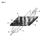
Figure 1. Schematic representation of a separation device illustrating the purification
concept. The chamber 1 containing the solution to purify has one inlet 2 and one outlet 3,
located at opposite extremities and it is covered by the chemical buffering system 4. The
cathode 5 and the anode 6 are placed parallel to the chamber and are only in contact with
the chemical buffering system. The black arrows indicate the penetration of positively
(versus cathode) or negatively (versus anode) charged compounds into the chemical
buffering system, whereas the white arrows indicate that a flow of solution can be induced
in the chamber.
Figure 2. Simulation results for an electric field applied to a gel matrix and its effects on
the solution for two values of the gel and solution conductivity σ.
A)
I: Potential distribution in the device when σ(gel) = σ(solution) II: Current vectors when σ(gel) = σ(solution) B)
III: Potential distribution in the device when 10σ(gel) = σ(solution) IV: Current vectors when 10σ(gel) = σ(solution)
Figure 3. Photograph of a prototype of separation device showing an arrangement similar
to that represented in Figure 1. The chamber 1 possesses one inlet 2 and one outlet 3 that
are connected to tubings to permit analyte solution flow through the device. The chemical
buffering system 4 is an immobilised pH gradient (IPG) gel placed above the chamber. The
entire device is held in a screwed Plexiglas support 8, and its integrity is ensured by an o-ring
7 which allows a tight seal. The cathode 5 and the anode 6 are placed in contact only
with the IPG gel, close to the o-ring. These electrodes are made of a thin platinum wires, so
that they can go above the o-ring without generating any leakage in the device. When the
gel reswells in the device, it encloses the electrodes completely and prevents the analyte
solution from touching the electrodes.
Figure 4. A) Photograph of an immobiline gel at pH=7 ± 0.14 pH units after purification in
the separation device of Figure 3 of a solution of IEF markers in water upon application of
an electrical field of 100 V during 1 hour. The migration of the negatively charged protein
phycocyanin (band 9) to the anode and of the positively charged proteins like cytochrome c,
myoglobin and haemoglobin (band 10) to the cathode is visible by eye in this experiment.
B) schematic diagram showing the separation process in the immobilised pH gradient gel.
The arrow indicates the direction of the pH gradient (low pH value at the anodic side of the
gel and high pH value at the cathodic side of the gel). During the separation, a compound X
with a pI corresponding to the pH of the portion of the gel in contact with the analyte
solution is globally neutral and does not migrate. A compound Y with a pI(Y)>pI((X) is
negatively charged in this pH range and migrates toward the anode, whereas a compound Z
with pI(Z)<pI(X) is positively charged in this pH range and migrates toward the cathode.
The dotted arrows indicate the direction of the migration of these various compounds.
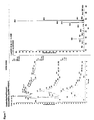
Figure 5. Purification experiment using a segment from pH 4 - 5.5 from an immobiline
DryPlate.
A) Electropherogram obtained from CIEF analysis of IEF standards as applied for the
experiment. Peaks 11 to 21 corresponds to the proteins of Table 1 below C) Electropherogram of the solution obtained after the experiment, showing that only peaks
11 and 12 remain of large intensity after purification.
Figure 6. Purification of a mixture containing 5 different proteins, namely: trypsin inhibitor
(pI=4.6, peak number 25), β-lactoglobuline B (pI=5.2, peak number 26), β-lactoglobuline A
(pI=5.3, peak number 27), equine myoglobine (pI=7.0, peak number 28) and equine
cytochrome c (pI=9.6, peak number 29).
A) CIEF analysis of: I) the applied protein mixture to purify; II) the protein solution after
the separation experiment with an immobiline section of a pH range between 5.06 to 5.34. B) Scheme for the separation principle of the present experiment in a separation device
when using an immobiline gel with a pH gradient. The protein of interest (noted A in the
scheme) has a pI in between the extremes of the pH gradient, i.e. between pH 5 and 5.4 in
the present case. Proteins symbolised by B and C in the scheme have a pI larger than 5.4 or,
respectively, smaller than 5.0, so that they are positively and, respectively, negatively
charged in the immobilised pH gradient gel. The dotted arrows show the direction of the
migration of these various proteins, whereas the solid arrow shows the direction of the pH
gradient between the anodic and the cathodic extremities of the gel (noted by a positive
and, respectively a negative sign). Upon application of the electric field, proteins of types B
and C migrate into the immobiline gel and are thus separated from the proteins of type A.
Figure 7. Mass spectrum (on the right side of the figure) obtained by single syringe
injection of 2 µL of a solution of 80 µM catechine and 20 µM methylene blue, including
(on the left side of the figure) the evolution with time of the relative abundance of the peaks
of mass 290.5-291.5 (upper graph), of the peak of mass 285.5-286.5 (middle graph) and of
the total abundance of these two peaks (bottom graph).
Figure 8. Mass spectrum (on the right side of the figure) obtained by continuous injection
of a purified solution of 80 µM catechine and 20 µM methylene blue, including (on the left
side of the figure) the evolution with time of the relative abundance of the peaks of mass
290.5-291.5 (upper graph), of the peak of mass 285.5-286.5 (middle graph) and of the total
abundance of these two peaks (bottom graph). These results are obtained by on-line
detection of the analyte solution that has previously flowed (without recycling) throughout
the chamber of the electrophoretic separation device (chemical buffering system: IPG gel
with the pH range 6-6.15 in contact with the analyte solution; applied electrical potential:
300 V, pumping rate 1 mL/min)
Figure 9. Schematic representation of the set-up used for the electrophoretic separation in a
static mode in a device where the inlet and outlet ends are merged, so that the chamber 31
is used as a reservoir in which the analyte solution can be introduced before purification
and retrieved after purification. The analyte solution is only in contact with the chemical
buffering system 32, and the electrical potential is applied through the anode 33 and the
cathode 34 that are introduced in two reservoirs 35 and 36. The black arrow indicates the
direction of the pH gradient introduced in the chemical buffering system.
Figure 10. Photograph of an IPG gel after purification of a 300 mM methylene blue and 10
mM phenol red water solution using a device similar to that of Figure 9 and subsequent
detennination of the migrated methylene blue (spot number 39) and phenol red (spot
number 38) to the cathodic and anodic reservoirs, repectively. The figure also shows that no
colour is present after electrophoretic separation in the portion 37 of the gel that was in
contact with the analyte solution during the purification.
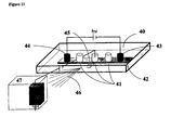
Figure 11. Schematic representation of the set-up that can be used for the electrophoretic
separation in a static mode with on-line detection using for example an electrospray mass
spectrometer. In this example, the device is supported in a plastic support 40 containing the
chamber 41 in contact with the chemical buffering system 42. The chamber is made of a
series of three subchambers 40 in which the inlet and outlet ends are merged, so that said
subchambers are used as reservoirs in which the analyte solution can be introduced before
purification. Two supplementary reservoirs 43 and 44 are used to introduce the electrodes
serving to apply the electrical field necessary for performing the electrophoretic
purification. The subchambers also contain a supplementary connection system 45 (only
one shown) for the coupling to another apparatus 47 serving as supplementary separation
step or as a detector. The figure shows that an electrical potential can be applied between
the subchambers (or a given position in the connection system) and the entrance of the
apparatus 47 in order to control the hydrodynamic flow of the purified solutions and/or to
generate an electrospray 46, thereby allowing to detect the compounds of interest present in
the purified analytical solution.
Detailed description
Example 1: Numerical Simulation of the Distribution of Migration Current within the
Device of the Invention
In order to understand the distribution of the migration current in the device of the
present invention, a numerical simulation can be run with a finite element calculation. Such
experiments allow one to predict the current flow through the purification device. To this
end, Figure 1 shows a schematic representation of an example of separation device and
illustrates the purification concept. In this example, the device consists of a chamber 1
containing the solution to purify with one inlet 2 and one outlet 3 at each extremity of the
chamber, of a chemical buffering system 4 in contact with a portion of the chamber and of
two electrodes (a cathode 5 and an anode 6) that are only in contact with the chemical
buffering system and placed parallel to the chamber. The black arrows indicate the
penetration of positively (versus cathode) or negatively (versus anode) charged compounds
into the chemical buffering system upon application of an electrical field between the two
electrodes, whereas the white arrows indicate that a flow of solution can be induced in the
chamber.
A cross section of the device, composed of a chemical buffering system as the cover
of a channel is simulated, and the migration current is calculated in each point of the
section. Two different cases have for example been simulated in the device where (i) the
conductivity σ is identical in the gel and in the solution (σ
gel = σ
solution) and (ii) the
conductivity in the gel is ten times lower than in the solution (10 σ
gel = σ
solution). For
both cases, a calculation is solved in each point of the structure following the Laplace
equation:
and using the appropriate conditions in a two-dimensional system:
at the first electrode:
U = 0,
at the second electrode:
U = 1,
at the insulating wall:
where
U is the potential (V) and σ is the electrical conductivity (.
-1·m
-1).
A stationary algorithm is used for the potential distribution. The simulations can be
run using a commercial finite element software, Flux Expert® (Simulog, France) operating
on a Unix workstation (Silicon Graphics Indigo 2 Solid Impact 10000 with 640 Mb RAM).
These simulation experiments aim at indicating whether the charged compounds
migrate into the chemical buffering system or not, and at demonstrating the influence of the
conductivity σ on the migration or in other words, the effect of the buffer composition in
the solution to purify. The obtained results are presented in Figure 2.
In the first case (Figure 2A), σ is considered to be equal in the chemical buffering
system and in the analyte solution (σgel = σsolution). A potential difference is applied
between the two electrodes, which allows the prediction of the potential distribution. Figure
2AI shows that the potential distribution in the solution corresponding to the segment under
the gel is closely similar to that in the chemical buffering system. A potential gradient is
also created in the chemical buffering system, which can lead to a pre-migration of proteins
in the solution depending on their charge. As shown in Figure 2AII, the current vectors
indicate that the current is also transported through the solution. The vectors are similar in
the middle of the structure and lead to an equal current flow. At the interface between the
chemical buffering system and the solution, it is clearly demonstrated that a current flow
takes place from the solution to the chemical buffering system.
In the second case (Figure 2B), the conductivity of the solution is enhanced. It is
considered 10 times higher in the analyte solution than in the gel (10 σgel = σsolution). The
result of this experiment is that the potential gradient in the solution is less effective (see
Figure 2BIII), but that more current is transported in the solution than in the chemical
buffering system (see Figure 2BIV). It can also be demonstrated, as in the first case, that a
current flow takes place from the solution to the chemical buffering system which enables
the proteins to enter the chemical buffering system from the solution by migration.
From these two experiments, the concept of the separation and purification device
of the present invention may be demostrated. Even if the potential is only applied to the
chemical buffering system, the analyte solution adjacent to it is affected by this potential,
and a migration of charged compounds (for example proteins) is induced. The two cases
differ only in their effectiveness. In the second case, a higher conductivity is considered,
corresponding to, for example, a buffered protein solution. This is certainly more desirable
for the protein stability and if the charge of some proteins have to be pre-selected for an
isoelectric separation experiment. On the other hand, it is clear that the first case favours
protein migration and therefore also the effectiveness of the purification device as nearly
100% of the current is carried by proteins in, for example, a non-buffered solution (sample
diluted in water).
Example 2: Electrophoretic Separation and Purification in a Non-Buffered Solution
In order to demonstrate the electrophoretic separation and purification of various
solutions, the following experimental conditions have been employed:
Reagents
IEF protein marker standard is obtainable from BioRad (Herkules, US). Equine
cytochrome c, β-lactoglobuline A and B, trypsin inhibitor and equine myoglobin can be
purchased from Sigma. Immobiline DryPlates pH range (4.5-5.4 and 4-7, 11 cm) are
obtainable from Pharmacia Amersham. The reagents for capillary isoelectric focusing
(CIEF) are all obtainable from BioRad.
Experimental setup
A plastic holder can be constructed in such a manner that the solution to purify can
be pumped through the device containing the chamber contacting the chemical buffering
system (which is an immobiline gel in the present case). Figure 2 shows a photograph of a
prototype of separation and purification device that has such an arrangement. The chamber
1 possesses one inlet 2 and one outlet 3 that are connected to teflon tubes and a peristaltic
pump (not shown) in order to let the analyte solution flow through the device. The chemical
buffering system 4 is an immobilised pH gradient (IPG) gel placed above the chamber. The
entire device is held in a screwed plastic support 8, and its watertightness is ensured by an
o-ring 7 wich allows a tight seal. The cathode 5 and the anode 6 are placed in contact only
with the IPG gel, close to the o-ring. These electrodes are made of thin platinum wires, so
that they can be integrated above the o-ring without generating any leakage in the device.
When the gel re-swells in the device, it encloses the electrodes completely and prevents the
analyte solution from touching the electrodes. Re-swelling of the gels can be achieved for
1h up to overnight in water or in the buffer system in which the purification experiment can
be carried out.
Purification
The different protein solutions (1ml total volume) can be applied to the device using
the peristaltic pump. Before the experiment, the solution can be circulated for at least 2
min, and a sample of 100 µl can be taken for CIEF. A constant voltage varying from 30-100
V according to the experiment can then be applied using a high voltage power supply
(Spellmann, CZE1000, New York, US). Voltage and current can be recorded with a
LabVIEW 5 program operated on a Digital PC and a data acquisition board (Lab PC+,
National Instruments, US).
Capillary Isoelectric Focusing (CIEF)
A Biofocus 3000 apparatus (BioRad, Hercules, US) can be used for CIEF analysis
using BioCap XL coated capillaries (ID 50 µm, BioRad). The protein samples can be
diluted in ampholytes (Bio-Lyte, BioRad) and analysed using BioRad IEF catholyte,
anolyte and mobiliser. When necessary the samples can be ultracentrifugated with Biomax
5kDa filters (Millipore, Bedford, Massachusetts, US) prior to dilution in ampholytes, in
order to guarantee sufficient concentration of proteins for the CIEF analysis.
Photography
Digital photographs of the dried immobiline gels and the device after the
experiments can be taken with a digital camera (Fuji MX-700, Fuji Photo Film, Tokio,
Japan) and treated with Adobe Photoshop software.
Example 2.1: Separation of Protein Markers at pH 7
In order to demonstrate protein migration as predicted in the simulation of the first
case of Example 1 where the gel and solution have identical conductivity, an immobiline
gel of a pH range between 6.9-7.1 can be integrated in a prototype of device as claimed by
the present invention (see Figure 3).
A solution of protein IEF markers in water (concentration of approx. 150mg/ml,
protein composition see Table 1) can be applied and continuously circulated through the
device of Figure 3 using a peristaltic pump at a constant pump rate (0.6 ml/min). A
photograph of the immobiline gel after 1 hour purification upon application of an electrical
potential of 100 V is shown in Figure 4. For this experiment, the portion of the IPG gel in
contact with the analyte solution has a pH of 7 ± 0.14. This figure shows a blue band 9,
indicating the migration of the blue coloured protein phycocyanin towards the anode and a
brown band 10, indicating cytochrome c, myoglobin and haemoglobin migrating towards
the cathode.
The proteins are concentrated in bands which demonstrate an electrophoretic
focalisation mechanism. This clearly indicates that protein migration is induced from the
solution to the gel, although the electrical potential is applied from electrodes only in
contact with the gel. This also empirically confirms that the above simulation data agree
with the experiment.
Example 2.2: Purification of beta-Lactoglobuline B and Phycocyanin from a
IEF Marker Solution
In a further experiment, the purification of a solution consisting of the IEF marker
proteins of Table 1 is demonstrated with a gel of pH range 4 - 5.5 with the pH gradient
parallel to the Platinum electrodes. A CIEF analysis is carried out before and after the
purification experiment (pump rate 0.6 ml/min, constant voltage = 50 V). As presented in
Figure 5, the comparison of the two electropherograms demonstrates that the proteins of the
original analyte solution with pI values higher than 5.5 migrated into the gel, whereas beta-lactoglobuline
B and phycocyanin (peaks 11 and 12) are still contained in the solution after
electrophoretic purification.
A simple comparison can also be carried out by eye. The solution before the
experiment is green (colour of the complex solution of IEF markers) whereas the solution is
blue after the purification (corresponding to the colour of phycocyanin). Additionally, the
gel only exhibits a brown colourat the cathode side, corresponding to the positively charged
proteins migrating towards it.
This experiment demonstrates that an analyte solution containing compounds of
interest can be purified by extraction of charged compounds using a device and method of
the present invention.
Example 2.3: Purification of beta-Laglobulines A and B
A protein solution consisting of five proteins with known isoelectric points (trypsin
inhibitor (pI=4.6), beta-lactoglobulin A (pI=5.3), beta-lactoglobulin B (pI=5.2), equine
myoglobin (pI=7.0), cytochrome c (pI=9.6), at a concentration of 200 µg/ml except trypsin
inhibitor with 50 µg/ml in water) is applied to the device of Figure 3 containing an
immobiline gel of a pH range from 5 to 5.4, rehydrated in water. As illustrated in the
scheme of the separation process of Figure 6B, the aim of this experiment is to recover
beta-lactoglobulines A and B in solution. To this aim, the purification is based on the
following principle: proteins with 5.0<pI<5.4 are either charged negatively in the gel near
the cathode and repelled (pH in gel > pI), as illustrated by the proteins of type A in Figure
6B. On the other more acidic gel extremity near the anode, these proteins of type A are
positively charged (pH in gel < pI) and again repelled. In this manner, they cannot be
extracted from the analyte solution. All other proteins with pI>5.4 are positively charged
and attracted to the cathode (proteins of type B in Figure 6B), whereas all proteins with
pI<5.0 are attracted by the anode (proteins of type C in Fgiure 6B). These last two types of
compounds are thus extracted into the IPG gel upon electrophoretic purification of the
analyte solution.
The electropherograms of the solution of the five above proteins are examined
before and after purification and the results reported in Figure 6A I and II show that the
proteins trypsin inhibitor, equine myoglobin and equine cytochrome c disappeared nearly
totally after purification, whereas the two beta-lactoglobulins stay in the solution. This is a
clear proof for the purification principle based on isoelectric separation according to the
present invention.
One advantage of the device as claimed in this invention is that the proteins to be
purified are in minimal contact to the immobiline matrix, which reduces possible effect the
polyacrylamide matrix could have on the proteins. They can be recovered easily in solution
for further analysis. No extraction with chemicals needs to be carried out, minimising the
effect of chemicals to the protein of interest. This fact also reduces the purification time.
We could show here that the purification of microgram quantities can be carried out in 1h.
It may even be enhanced with the use of a cooling device or a different geometry ensuring
less current flow through the device. This would allow the application of a higher electrical
potential.
Example 3: Electrophoretic Separation in a Buffered Solution
To test the simulation of the second case of the simulation experiment of example 1
where the conductivity of the gel is ten times lower that the solution, the solution of the
protein markers of Table 1 is adjusted to a given pH. An acetate buffer (0.01 M) with a pH
of 4.6 is used for this purpose. This pH corresponds to the pI of phycocyanin which is
contained in the IEF marker standard (see Table 1). The pH range of the gel varied between
4.5-4.58 and 4.58-4.66. In these experiments, the current is set constant to 300 µA, which is
the upper limit of the power supply. The voltage that has been detected to never exceed 30
V. After several hours of electrical potential application, only very little protein is visible in
the gel (results not shown). These proteins are very diffuse and not focused in a band as in
the above experiments. Also, bubble formation is enhanced, thereby causing a certain
destruction of the gel in the device.
These experiments clearly show that the migration efficiency of the proteins is
dramatically decreased if the sample solution is buffered. It is clear that more current is
carried by buffering ions, when their concentration is high in comparison to that of the
protein mixture. On the contrary, the current is mainly transported by the proteins
themselves when they are contained in water only. This favours protein migration and
therefore the separation efficiency of the device. While water is not the most favoured
analyte solvent for proteins, the above method does not need any addition of buffer ions or
ampholytes for the enhancement of isoelectric separation. In a practical point of view, this
greatly facilitates the separation process.
Example 4: Electrophoretic Purification Coupled with On-line Mass Spectrometry
Detection
A device similar to that shown in Figure 3 can be coupled to a mass spectrometer
(LCQ-DUO, Finnigan) for on-line detection of the compound or compounds of interest. To
this aim, a mixture of 80 µM catechine and 20 µM methylene blue can be pumped through
the electrophoretic separation device at a rate of 1 mL/min (using a peristaltic pump from
Ismatec). The device contains a chemical buffering system made of an IPG gel of pH 5.5 to
6.5, so that the portion of the gel in contact with the chamber exhibits the pH range 6-6.15.
The outlet end of the chamber is connected by tubings to the injection system of a LCQ-DUO
mass spectrometer for on-line analysis of the solution.
Catechine is a well-known mass marker that is neutral between pH 6 and 6.15,
whereas methylene blue is a permanent cation. When this mixture flows in the device of the
present invention, methylene blue is extracted out of the analyte solution and penetrates
into the IPG gel upon application of an electrical potential (for example 300 V). In this
manner, methylene blue is eliminated from the solution, and the catechine is purified. This
is evidenced in Figures 7 and 8 that show the mass spectrogram of the analyte solution
before and, respectively, after electrophoretic purification. To this end, the results of Figure
7 have been obtained with 1 µL of the starting analyte solution that has been electrosprayed
from a syringe in the mass spectrometer (in atmospheric pressure chemical ionisation
(APCI) mode, with nitrogen as sheath gas and with the following working conditions:
voltage source: 3.82 kV; current source: 5.4 mA; vaporizer temperature: 450°C; sheath gas
flow rate: 79.9 psi; capillary voltage: 4.6 V and capillary temperature: 200°C). The
obtained spectrum mainly shows two very strong peaks at the mass/charge (m/z) ratios of
286.3 and 291 corresponding to methylene blue and catechine, respectively. The intensity
of the peak at m/z = 291 is only about 60% that of the peak at m/z = 286.3, in agreement
with the larger concentration of methylene blue in the analyte solution. After
electrophoretic purification of the analyte solution, the mass spectrum of Figure 8 exhibits a
similar shape, but the relative abundance of the peaks become almost the same (the
intensity of the peak at m/z = 291 is 94% that of the peak at m/z = 286.3). The experiment
can be run further, and the evolution of the relative abundance of the two peaks with time
shows that the intensity of the peak at m/z = 291 remains approximately constant, whereas
that of the peak at m/z = 286.3 passes from 100% to less than 40% within less than two
minutes.
These results clearly indicate that the analyte solution has been purified, in
agreement with the blue band of methylene blue observed in the gel close to the cathode.
The length of the chamber (about 3 cm) is not sufficient to completely eliminate methylene
blue from the analyte solution, but the dimension of the chamber, the flow rate of the
analytical solution as well as the value of the electrical field can be optimised to allow
complete purification.
This experiment clearly demonstrates that the device of the present invention can be
coupled to a mass spectrometer for on-line detection of the purified solution. In this
manner, further separation or detection of the purified solution can be easily conducted. In
some applications, the purified fractions can also be collected in another support before
further analysis, like for instance a MALDI (matrix assisted laser desorption ionisation)
plate.
Example 5: Electrophoretic Purification of Isoforms
In order to demonstrate the separation and purification of protein isoforms, N-acetyl
Eglin C is obtainable by recombinant DNA techniques containing two isoforms (one in
basic pH and one in acid pH range).
A water solution of 1mg/mL N-acetyl Eglin C can be recycled in the device of the
present invention and run constantly at 1000 volts for 1 hour on an immobilsed pH gradient
gel at pH 5.5 (pI of N-acetyl Eglin C).
The results that can be obtained using a conventional capillary isoelectric focusing
apparatus (Biofocus, Bio-Rad) show that the analyte solution to purify presents one peak
after 26.86 min. (corresponding to the basic isoform pI 6.2: 4.86%), a main peak after 29.56
min. (corresponding to Eglin C: 90.18%) and a peak after 31.52 min. (corresponding to the
acid isoform pI 5.2: 4.94%). After separation and purification according to the method of
the present invention, the purified solution shows a very small peak corresponding to a
trace of basic isoform at 26.38 min. And a peak at 29.57 min. (97.88%) corresponding to
the main component of N-acetyl Eglin C. No peak corresponding to the acid isoform is
present, demonstrating the isoform separation and purification and the enrichment of the
main component.
Example 6: Electrophoretic Purification in Static Mode
For certain applications, it may be advantageous to purify the analyte solution
without hydraulic flow. In such cases, the device of the present invention does not require a
chamber with inlet and outlet ends, but only a reservoir to introduce the analyte solution
and retrieve it.
This is exemplified in Figure 9 which shows a schematic representation of the set-up
used for the electrophoretic separation in a static mode in a device where the inlet and
outlet ends are merged, so that the chamber 31 is used as a reservoir in which the analyte
solution can be introduced before purification and retrieved after purification. The analyte
solution is only in contact with the chemical buffering system 32, and the electrical
potential is applied through the anode 33 and the cathode 34 that are introduced in two
reservoirs 35 and 36. The black arrow indicates the direction of the pH gradient introduced
in the chemical buffering system.
For the demonstration of the separation with such a device of the present invention,
one can fabricate an electrophoretic separation device similar to that shown in Figure 9
which includes an immobilised pH gradient (IPG) gel serving as chemical buffering system
and a chamber containing three sub-chambers consisting of small plastic tubes that are
placed on the top of the IPG gel and disposed along the direction of the pH gradient. As
schematically illustrated in Figure 9, the analyte solution can be introduced into the central
subchamber, whereas the two other subchambers are filled with water and contain each an
electrode so as to serve as cathodic and anodic reservoirs, respectively. In this manner, the
electrodes are not directly in contact with the analyte solution. The electrical field has to
pass through the IPG gel, and a portion of the electric field penetrates into the subchamber
containing the analyte solution to purify.
To demonstrate the separation and purification of an analyte solution with such a
configuration of electrophoretic device, an immobiline gel (pH range 4-7) can be reswelled
in water overnight at room temperature. Three plastic wells (1 cm diameter) with holes (0.8
cm in diameter) opened in their bottom can be placed on top of the IPG gel, respectively on
the pH 4.5, pH 5.5 and pH 6 lines. One hundred µL of a 300 µM methylene blue and 10
mM phenol red water solution can then be deposited in the central well in contact with the
gel at pH 6. Two platinum electrodes can be respectively placed in the right and left side
wells which are filled with water.
In these conditions, both compounds are charged over the whole pH range imposed
by the IPG gel, since methylene blue is a permanent cation and phenol red is negatively
charged below its pKa which has a value of 7.81. Methylene blue exhibits a blue colour
whereas phenol red is yellow in its anionic form, so that extraction of both analytes out of
the analyte subchamber into the IPG gel upon application of an electrical potential can be
easily identified. Indeed, upon application of a constant voltage (500 V) between the two
platinum electrodes using a high voltage power supply (Landis & Gyr), it can be seen that
methylene blue migrates towards the cathode, whereas phenol red migrates towards the
anode. After one hour of purification, a digital photograph of the gel is taken with a
numerical camera (Camedia C-2020 Z ― Olympus) and treated with Olympus Camedia
software. This photograph of the IPG gel presented in Figure 10 shows that the purification
is complete, which is demonstrated by the the fact that the central reservoir is colourless
(absence of colour in the portion 37 of the gel that was in contact with the analyte
reservoir), whereas the portion of the gel below the anodic reservoir is yellow (spot 39 in
Figure 10) and that below the cathodic reservoir is blue (spot 39 in Figure 10).
These results clearly demonstrate the efficiency of the method of the present
invention, even when no flow is induced to the analyte solution to purify. However,
agitation may be induced either to the subchambers or to the entire device, so as to increase
the convection. As the efficiency and rate of the separation depends on the migration of the
charged compound in the analyte solution, it may be advantageous to avoid the formation
of concentration gradients and hence to insure homogeneity of the analyte solution. For
certain applications like protein purification, it can also be advantageous to control the
temperature of the subchambers and to add means of avoiding precipitation (for example by
sonicating the subchambers).
It is worth noting here that the solutions in the anodic and cathodic reservoirs can be
slightly coloured at the end of the purification. In such a case, this indicates that part of the
methylene blue and part of the phenol red are extracted out of the IPG gel into the anodic
and, repectively, the cathodic reservoirs, thereby allowing to recover in solution the
compounds that have been extracted from the analyte solution into the chemical buffering
system. This can be useful in many applications and demonstrates one interest of disposing
a plurality of sub-chambers in the separation device so as to collect various purified
fractions, as specified in some embodiments of the present invention.
An example of purification device containing a plurality of subchambers is shown
in Figure 11 which is a schematic representation of the set-up that can be used for the
electrophoretic separation in a static mode with on-line detection or connection to a further
separation step. In this illustration, the device is supported in a plastic support 40
containing the chamber 41 in contact with the chemical buffering system 42. The chamber
is made of a series of subchambers 41 in which the inlet and outlet ends are merged, so that
said subchamber are used as reservoirs in which the analyte solution can be introduced
before purification and retrieved after purification. Only three subchambers are represented
here, but there is no limitation in the number, disposition and shape of these subchambers.
Two supplementary reservoirs 43 and 44 are used to introduce the electrodes serving to
apply the electrical field necessary for performing the electrophoretic purification. The
subchambers also contain a supplementary connection system 45 (only one shown) for the
coupling to another apparatus 47 serving as supplementary separation step or as a detector.
The figure shows that an electrical potential can be applied between the subchambers (or a
given position in the connection system) and the entrance of the apparatus 47 in order to
control the hydrodynamic flow of the purified solutions and/or to generate an electrospray
46, thereby permitting detection of the compounds of interest present in the purified
analytical solution.
Finally, recovery of the compound or compounds of interest in solution greatly
facilitates further separation, purification and/or detection. To this end, the subchambers of
the devices described in the present experiment can contain a connection (like for example
an aperture, a groove, a sealed tube, a capillary, a sealed micro-channel or any other
coupling system) that allows on-line introduction or injection of the purified solution into
another detection system (see Figure 11 for an example). Such a system can be
demonstrated with a conventional liquid chromatograph that is used for example to further
separate a cellular extract that has been purified by the electrophoretic method of the
present invention and that contains several compounds of interest that need to be identified
individually. Similarly, the subchambers of the present device can for example be directly
coupled to a mass spectrometer (with direct sampling using aspiration, mechanical or
electrokinetic pumping), thereby allowing on-line identification of the compound or
compounds of interest.
Although the foregoing invention has been described in some
detail by way of illustration and examples for clarity of understanding, it will be readily
apparent to a person skilled in the art in light of the teachings of this invention that certain
changes and modifications may be made thereto without departing from the scope
of the appended claims.