EP1281878B1 - Pivot pin between two elements - Google Patents
Pivot pin between two elements Download PDFInfo
- Publication number
- EP1281878B1 EP1281878B1 EP02291615A EP02291615A EP1281878B1 EP 1281878 B1 EP1281878 B1 EP 1281878B1 EP 02291615 A EP02291615 A EP 02291615A EP 02291615 A EP02291615 A EP 02291615A EP 1281878 B1 EP1281878 B1 EP 1281878B1
- Authority
- EP
- European Patent Office
- Prior art keywords
- pin
- head
- connecting shaft
- grooves
- bolt
- Prior art date
- Legal status (The legal status is an assumption and is not a legal conclusion. Google has not performed a legal analysis and makes no representation as to the accuracy of the status listed.)
- Expired - Lifetime
Links
- 239000002184 metal Substances 0.000 claims abstract description 5
- 210000002445 nipple Anatomy 0.000 claims description 3
- 239000007769 metal material Substances 0.000 claims 1
- 238000004519 manufacturing process Methods 0.000 description 3
- 230000000903 blocking effect Effects 0.000 description 2
- 239000000470 constituent Substances 0.000 description 2
- 238000012423 maintenance Methods 0.000 description 2
- 239000000463 material Substances 0.000 description 2
- 241000920340 Pion Species 0.000 description 1
- 238000005266 casting Methods 0.000 description 1
- 230000007246 mechanism Effects 0.000 description 1
- 238000012986 modification Methods 0.000 description 1
- 230000004048 modification Effects 0.000 description 1
- 230000002028 premature Effects 0.000 description 1
- 230000000452 restraining effect Effects 0.000 description 1
- 210000002105 tongue Anatomy 0.000 description 1
- 238000012795 verification Methods 0.000 description 1
Images


Classifications
-
- F—MECHANICAL ENGINEERING; LIGHTING; HEATING; WEAPONS; BLASTING
- F16—ENGINEERING ELEMENTS AND UNITS; GENERAL MEASURES FOR PRODUCING AND MAINTAINING EFFECTIVE FUNCTIONING OF MACHINES OR INSTALLATIONS; THERMAL INSULATION IN GENERAL
- F16B—DEVICES FOR FASTENING OR SECURING CONSTRUCTIONAL ELEMENTS OR MACHINE PARTS TOGETHER, e.g. NAILS, BOLTS, CIRCLIPS, CLAMPS, CLIPS OR WEDGES; JOINTS OR JOINTING
- F16B19/00—Bolts without screw-thread; Pins, including deformable elements; Rivets
- F16B19/04—Rivets; Spigots or the like fastened by riveting
- F16B19/08—Hollow rivets; Multi-part rivets
- F16B19/10—Hollow rivets; Multi-part rivets fastened by expanding mechanically
- F16B19/1027—Multi-part rivets
- F16B19/1036—Blind rivets
- F16B19/1081—Blind rivets fastened by a drive-pin
-
- F—MECHANICAL ENGINEERING; LIGHTING; HEATING; WEAPONS; BLASTING
- F16—ENGINEERING ELEMENTS AND UNITS; GENERAL MEASURES FOR PRODUCING AND MAINTAINING EFFECTIVE FUNCTIONING OF MACHINES OR INSTALLATIONS; THERMAL INSULATION IN GENERAL
- F16B—DEVICES FOR FASTENING OR SECURING CONSTRUCTIONAL ELEMENTS OR MACHINE PARTS TOGETHER, e.g. NAILS, BOLTS, CIRCLIPS, CLAMPS, CLIPS OR WEDGES; JOINTS OR JOINTING
- F16B21/00—Means for preventing relative axial movement of a pin, spigot, shaft or the like and a member surrounding it; Stud-and-socket releasable fastenings
- F16B21/10—Means for preventing relative axial movement of a pin, spigot, shaft or the like and a member surrounding it; Stud-and-socket releasable fastenings by separate parts
- F16B21/12—Means for preventing relative axial movement of a pin, spigot, shaft or the like and a member surrounding it; Stud-and-socket releasable fastenings by separate parts with locking-pins or split-pins thrust into holes
- F16B21/125—Means for preventing relative axial movement of a pin, spigot, shaft or the like and a member surrounding it; Stud-and-socket releasable fastenings by separate parts with locking-pins or split-pins thrust into holes radially resilient or with a snap-action member, e.g. elastic tooth, pawl with spring, resilient coil or wire
-
- F—MECHANICAL ENGINEERING; LIGHTING; HEATING; WEAPONS; BLASTING
- F16—ENGINEERING ELEMENTS AND UNITS; GENERAL MEASURES FOR PRODUCING AND MAINTAINING EFFECTIVE FUNCTIONING OF MACHINES OR INSTALLATIONS; THERMAL INSULATION IN GENERAL
- F16C—SHAFTS; FLEXIBLE SHAFTS; ELEMENTS OR CRANKSHAFT MECHANISMS; ROTARY BODIES OTHER THAN GEARING ELEMENTS; BEARINGS
- F16C11/00—Pivots; Pivotal connections
- F16C11/02—Trunnions; Crank-pins
Definitions
- the present invention relates to an axis of pivot connection between two parts, comprising a pawn adapted to traverse at least one hole practiced in each room and a lock adapted to surround the pawn and including means to block the axis in translation arranged to each of its ends and means of retaining the pin in the lock.
- It relates more particularly to an axis pivot connection of a brake pedal which must be tied with the end of a rod brake amplifier of a vehicle automobile, said end being shaped clevis.
- the document FR 2 773 595 proposes a axis housed in a split sleeve in which is cut out a plurality of flexible legs orthogonal and tongues which on the one hand hold the axis in the sleeve and secondly ensure the attachment of the sleeve on the branches of the clevis of the amplifier rod braking.
- DE 40 10 466 also discloses a pawn housed in a sleeve that keeps it through a narrowed part of his body inserted in a transverse groove circular piece of the pawn, the sleeve acting as bearing around which the brake pedal pivots.
- the object of the invention is then to propose a link axis as mentioned in the preamble the assembly is simple and quick to perform and reliable.
- the subject of the invention is a pivot connection axis between two parts, comprising a pawn adapted to cross at the least one hole in each room and one lock adapted to surround the pawn and comprising means for blocking the axis translation arranged at each of its ends and means for retaining the pin in the lock remarkable in that the pawn includes substantially throughout its length at least two grooves and in that the lock comprises, in as a means of blocking, a head and feet likely to deviate from each other and, as restraining means, at least two arm of length substantially equal to and section combined with that of the grooves and connecting the head to the feet, said arms being adapted to slide in the grooves and for spread your feet.
- the pawn comprises on one of its lateral faces a nipple adapted for facilitate the introduction of the axis into the holes parts placed next to each other.
- the pawn is made of material metallic.
- the lock is a monoblock piece.
- the pawn includes a circular head section and three rectangular section grooves and latch includes a circular section head adapted to come to lean against that of the pawn and three arms of slightly lower height to that of grooves.
- the axis according to this embodiment is very robust.
- the pawn advantageously comprises notches practiced at the opposite end of the head in which fingers integral with the lock head are likely to come into it.
- the axis includes notches practiced under the pawn's head and in which the fingers attached to the head of the lock are also likely to come there introduce.
- the pawn includes two grooves and the lock is consisting of a curved metal rod including the W-shaped head and two feet in the form of hooks.
- the pawn has two grooves and the lock includes two feet of longitudinal section triangular and an elastic head presenting four lobs arranged symmetrically to each other to the axis of rotation of the pawn and joined together by flexible legs.
- the axis according to these two last modes is easy to make and simple to set up in holes or bores of parts to to assemble.
- the invention also relates to the use of the axis that has just been described to achieve a pivot connection between the two branches of a clevis and a piece arranged between the two branches.
- the screed can be the end of an amplifier rod braking and the piece can be a pedal of brake of a motor vehicle.
- the invention finally relates to a pedal of brake of a motor vehicle connected to the rod braking amplifier by means of an axis of link as previously described.
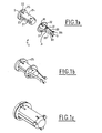
- FIG. 1a shows an axis of pivot connection according to a first mode of embodiment of the invention.
- This axis 1 is consisting of a metal pawn 2 of shape general cylindrical and 3-piece lock made of plastic that are manufactured independently of each other before their assembly and are held together before the mounting ( Figure 1b) in the holes of the parts to link.
- This maintenance is provided through three fingers 31 angularly distributed evenly on the lower part of the head 32 of circular section and which are introduced individually in a notch 21 practiced in the pawn 2 at the opposite end of the head 22 of the pawn.
- This maintenance of the axis according to the invention before mounting in the holes of the parts to bind facilitates its manipulation by the operator who must do the editing.
- the assembly time is also faster, which can be advantageous when assembling the two parts between them, for example between the pedal of brake and the rod of the brake booster, must be done on industrial line.
- the pawn 2 also has three grooves longitudinal 23 of rectangular section evenly distributed around the body 24 of the pawn 2 and practiced substantially on all length of the pawn 2. It also presents three notches 25 practiced immediately below of the head 22 and angularly distributed uniformly. These notches 25 allow the introduction of the fingers 31 of the lock 3 when the establishment of the whole axis in the holes of the pieces to be bonded is carried out.
- the lock 3 also includes three arms 33 connecting the head 32 of the lock 3 to the feet 34 who came from casting with the whole of latch and which are bent towards the head 32 of lock forming a loop. These arms 33 a height significantly lower than that of arm 33 so they do not protrude into outside the grooves 23 after mounting of the set in the holes of the pieces to bind and so when the lock head 32 is in contact with that of the pawn 2 ( Figure 1c).
- the assembly is completed when the spacing between arms 33 has reached the value of diameter of the pin 2 and that the head 32 of the lock comes in support against that 22 of the pawn 2, the fingers 31 being introduced into the notches 25.
- the feet 331 of the lock then protrude out of axis 1 and are likely to block in translation the axis according to invention and therefore maintain this one introduced permanently into the bores 41,51 of the two pieces to be assembled between they.
- the two pieces 4,5 are thus maintained between them and can rotate relative to each other to the other around the axis 1 according to the invention.
- Axis 1 made according to the mode that comes to be described is very robust.
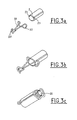
- FIGS. 3a to 3c there is shown a second embodiment of the axis 1 conforming to the invention respectively before assembly between the two parts of the axis, before their introduction into the holes of the pieces to assemble and once the editing done.
- the cylindrical pin 2 comprises two longitudinal grooves 23 of semicircular section practiced substantially over the entire length of the pin 2 and diametrically opposite.
- the pawn also includes a spur 26 on one of its side faces. This nipple 26 facilitates the introduction of the pin 2 into the lock 3 associated and in the holes of the pieces to to assemble between them.
- the lock 3 according to the invention is a metal rod of circular section folded on itself and whose two branches constitute arms connecting the feet 331 hook-shaped to a 32 head in the shape of W.
- Axis 1 made according to this mode is very easy to manufacture and also to put in place in the holes of the parts to be assembled.
- FIGS. 4a to 4c there is shown a third embodiment of the axis 1 according to the invention respectively before the assembly between the two parts of the axis, before their introduction into the holes of parts to assemble and once the assembly realized.
- the pawn 2 is identical with that of the second mode except that the section of the grooves 23 is rectangular.
- the lock 3 is a piece of plastic monobloc whose arms 33 connect the feet 331 triangular longitudinal section to the head 32 having four identical lobs 321 arranged symmetrically with respect to the axis of rotation of the pawn and joined together by elastic tabs 322, the approximation and the spacing makes it possible to exert an effort on the pion before the establishment of the axis 1 in the holes of the parts to be assembled, which allows a better hold of the pin 2 in the lock 3.
- the inner part of feet 331a constitutes stops coming to block in translation the axis according to the invention against outer face of the part to be assembled.
- the axis 1 realized according to this third mode is also very easy to manufacture and to put in place in the holes of the parts to be assembled.
- FIG. 5 there is shown a pedal brake 4 linked to rotation with a rod 5 braking amplifier by means of the axis according to the invention, the assembly thus constituted being implanted in a motor vehicle. More precisely the enlarged sectional view cross-section according to FIG. 5a shows the two branches 51,52 of the constituent scre the end of the amplifier rod braking clutching the brake pedal 4, the assembly being assembled by means of the axis 1 according to the invention.
- the invention which has just been described proposes so a mounting solution guaranteeing a effective positioning of the pivot connection between two rooms.
- the invention proposes a pivot link very reliable because it allows to avoid premature wear of the lock. Indeed, this one does not undergo any constraint functional mechanics that a lock undergoes of a traditional pivot link, because none of its parts are in direct contact with the bore of one or more parts to be assembled.
Abstract
Description
La présente invention concerne un axe de liaison pivot entre deux pièces, comprenant un pion adapté pour traverser au moins un trou pratiqué dans chaque pièce et un verrou adapté pour entourer le pion et comprenant des moyens pour bloquer l'axe en translation disposés à chacune de ses extrémités et des moyens de retenue du pion dans le verrou.The present invention relates to an axis of pivot connection between two parts, comprising a pawn adapted to traverse at least one hole practiced in each room and a lock adapted to surround the pawn and including means to block the axis in translation arranged to each of its ends and means of retaining the pin in the lock.
Elle concerne plus particulièrement un axe de liaison pivot d'une pédale de frein qui doit être liée avec l'extrémité d'une tige d'amplificateur de freinage d'un véhicule automobile, ladite extrémité étant en forme de chape.It relates more particularly to an axis pivot connection of a brake pedal which must be tied with the end of a rod brake amplifier of a vehicle automobile, said end being shaped clevis.
Pour réaliser une telle liaison, on a déjà proposé un axe en deux parties dont une est constituée d'un pion qui vient traverser le ou les trou(s) pratiqué(s) dans chaque pièce à assembler et l'autre est constituée d'un verrou qui vient entourer le pion et qui comprend d'une part des moyens pour bloquer l'axe en translation disposés à chacune de ses extrémités et d'autre part des moyens pour retenir le pion dans le verrou.To achieve such a link, we have already proposed a two-part axis of which one is consisting of a pawn that comes across the the hole (s) practiced in each room assemble and the other consists of a lock that comes around the pawn and that includes a means to block the axis translation arranged at each of its ends and on the other hand means to retain the pawn in the lock.
Ainsi le document FR 2 773 595 propose un
axe logé dans un manchon fendu dans lequel est
découpée une pluralité de pattes flexibles
orthogonales et de languettes qui d'une part
retiennent l'axe dans le manchon et d'autre part
assurent la fixation du manchon sur les branches
de la chape de la tige de l'amplificateur de
freinage.Thus the
Le montage de l'axe entouré de son manchon s'avère en pratique délicat à réaliser et le temps de montage qui y est consacré est assez long. En outre, ce montage n'est pas nécessairement très fiable car la pédale de frein est directement en contact avec le manchon lors du pivotement, ce qui augmente considérablement les contraintes mécaniques ede l'axe et donc l'usure du manchon.The mounting of the shaft surrounded by its sleeve turns out to be tricky in practice and the assembly time devoted to it is enough long. In addition, this montage is not necessarily very reliable because the pedal of brake is directly in contact with the sleeve when pivoting, which increases considerably the mechanical stresses the axis and therefore the wear of the sleeve.
Le document DE 40 10 466 divulgue également un pion logé dans un manchon qui le maintient par l'intermédiaire d'une partie rétrécie de son corps insérée dans une gorge transversale circulaire du pion, le manchon faisant office de palier autour duquel la pédale de frein pivote.DE 40 10 466 also discloses a pawn housed in a sleeve that keeps it through a narrowed part of his body inserted in a transverse groove circular piece of the pawn, the sleeve acting as bearing around which the brake pedal pivots.
Si le montage de ce type d'axe de liaison est relativement aisé et rapide à réaliser, il n'est pas nécessairement très fiable car la pédale de frein est directement en contact avec le manchon lors du pivotement, ce qui augmente considérablement les contraintes mécaniques de l'axe et donc l'usure du manchon.If mounting this type of link axis is relatively easy and quick to achieve, it is not necessarily very reliable because the brake pedal is directly in contact with the sleeve during pivoting, which increases considerably the mechanical stresses of the axis and therefore the wear of the sleeve.
Le but de l'invention est alors de proposer un axe de liaison tel que cité en préambule dont le montage soit simple et rapide à réaliser et fiable.The object of the invention is then to propose a link axis as mentioned in the preamble the assembly is simple and quick to perform and reliable.
Pour ce faire, l'invention a pour objet un axe de liaison pivot entre deux pièces, comprenant un pion adapté pour traverser au moins un trou pratiqué dans chaque pièce et un verrou adapté pour entourer le pion et comprenant des moyens pour bloquer l'axe en translation disposés à chacune de ses extrémités et des moyens de retenue du pion dans le verrou remarquable en ce que le pion comprend sensiblement sur toute sa longueur au moins deux rainures et en ce que le verrou comprend, en tant que moyens de blocage, une tête et des pieds susceptibles de s'écarter l'un de l'autre et, en tant que moyens de retenue, au moins deux bras de longueur sensiblement égale à et de section conjuguée à celle des rainures et reliant la tête aux pieds, lesdits bras étant adaptés pour coulisser dans les rainures et pour écarter les pieds.For this purpose, the subject of the invention is a pivot connection axis between two parts, comprising a pawn adapted to cross at the least one hole in each room and one lock adapted to surround the pawn and comprising means for blocking the axis translation arranged at each of its ends and means for retaining the pin in the lock remarkable in that the pawn includes substantially throughout its length at least two grooves and in that the lock comprises, in as a means of blocking, a head and feet likely to deviate from each other and, as restraining means, at least two arm of length substantially equal to and section combined with that of the grooves and connecting the head to the feet, said arms being adapted to slide in the grooves and for spread your feet.
Le montage d'un tel axe est très simple et rapide à réaliser puisque l'opérateur en charge du montage n'a pas à utiliser d'outil spécifique. En outre, un tel montage garantit la mise en place correcte du pion et de son verrou associé sans qu'il y ait de vérification supplémentaire à effectuer. Enfin, un tel montage est très fiable puisque le verrou selon l'invention ne subit pas les contraintes mécaniques fonctionnelles d'une liaison pivot classique car le verrou n'est pas au contact directement du trou ou de l'alésage de la pièce lors de son pivotement.The assembly of such an axis is very simple and quick to realize since the operator in charge mounting does not have to use tool specific. In addition, such an arrangement guarantees the correct placement of the pawn and its lock associated without verification additional to perform. Finally, such assembly is very reliable since the lock the invention does not suffer the constraints Mechanical mechanisms of a pivot link classic because the lock is not in contact directly from the hole or bore of the part when pivoting.
Avantageusement, le pion comprend sur l'une de ses faces latérales un téton adapté pour faciliter l'introduction de l'axe dans les trous des pièces placés en regard l'un de l'autre. Avantageusement encore, le pion est en matériau métallique.Advantageously, the pawn comprises on one of its lateral faces a nipple adapted for facilitate the introduction of the axis into the holes parts placed next to each other. Advantageously, the pawn is made of material metallic.
Selon une caractéristique avantageuse, le verrou est une pièce monobloc.Selon un premier mode de réalisation de l'invention, le pion comprend une tête de section circulaire et trois rainures de section rectangulaire et le verrou comprend une tête de section circulaire adaptée pour venir s'appuyer contre celle du pion et trois bras de hauteur légèrement inférieure à celle de rainures.According to an advantageous characteristic, the lock is a monoblock piece.According to a first embodiment of the invention, the pawn includes a circular head section and three rectangular section grooves and latch includes a circular section head adapted to come to lean against that of the pawn and three arms of slightly lower height to that of grooves.
L'axe selon ce mode de réalisation est très robuste.The axis according to this embodiment is very robust.
Selon ce mode de réalisation, le pion comprend avantageusement des encoches pratiquées à l'extrémité opposée de la tête dans laquelle des doigts solidaires de la tête du verrou sont susceptibles de venir s'y introduire.According to this embodiment, the pawn advantageously comprises notches practiced at the opposite end of the head in which fingers integral with the lock head are likely to come into it.
Ces encoches permettent de réaliser un bon prémaintien du verrou autour de l'axe avant la mise en place de l'ensemble dans les trous ou alésages des pièces à lier.These notches allow to make a good pre-locking the lock around the axis before the set up the whole in the holes or bores of the parts to be bonded.
Selon ce même mode, l'axe comprend des encoches pratiquées sous la tête du pion et dans lesquelles les doigts solidaires de la tête du verrou sont également susceptibles de venir s'y introduire.In the same way, the axis includes notches practiced under the pawn's head and in which the fingers attached to the head of the lock are also likely to come there introduce.
Selon un autre mode de réalisation,le pion comprend deux rainures et le verrou est constitué d'une tige métallique recourbée comprenant la tête en forme de W et deux pieds sous la forme de crochets.According to another embodiment, the pawn includes two grooves and the lock is consisting of a curved metal rod including the W-shaped head and two feet in the form of hooks.
Selon un autre mode encore de réalisation, le pion comprend deux rainures et le verrou comprend deux pieds de section longitudinale triangulaire et une tête élastique présentant quatre lobs disposés symétriquement par rapport à l'axe de rotation du pion et réunis entre eux par des pattes flexibles.According to another embodiment, the pawn has two grooves and the lock includes two feet of longitudinal section triangular and an elastic head presenting four lobs arranged symmetrically to each other to the axis of rotation of the pawn and joined together by flexible legs.
L'axe selon ces deux derniers modes est facile à réaliser et simple à mettre en place dans les trous ou alésages des pièces à assembler.The axis according to these two last modes is easy to make and simple to set up in holes or bores of parts to to assemble.
L'invention concerne également l'utilisation de l'axe qui vient d'être décrit pour réaliser une liaison pivot entre les deux branches d'une chape et une pièce disposée entre les deux branches.The invention also relates to the use of the axis that has just been described to achieve a pivot connection between the two branches of a clevis and a piece arranged between the two branches.
Selon cette utilisation, la chape peut être l'extrémité d'une tige d'amplificateur de freinage et la pièce peut être une pédale de frein d'un véhicule automobile.According to this use, the screed can be the end of an amplifier rod braking and the piece can be a pedal of brake of a motor vehicle.
L'invention concerne enfin une pédale de frein d'un véhicule automobile liée à la tige d'amplificateur de freinage au moyen d'un axe de liaison tel que décrit précédemment.The invention finally relates to a pedal of brake of a motor vehicle connected to the rod braking amplifier by means of an axis of link as previously described.
D'autres avantages de l'invention seront mieux compris à la lecture de la description détaillée d'un exemple selon l'invention faite en référence aux figures suivantes qui représentent :
- figures 1a à 1c : une vue en perspective d'un axe de liaison selon un premier mode de réalisation de l'invention, respectivement avant son assemblage, avant et après sa mise en place dans les trous des pièces à lier;
- figures 2a à 2c : une représentation schématique des différentes étapes de réalisation de la liaison pivot au moyen de l'axe slon les figures 1a et 1b ;
- figures 3a et 3b : une vue en perspective d'un axe de liaison selon un deuxième mode de réalisation de l'invention, respectivement avant et après sa mise en place dans les trous des pièces à lier;
- figures 4a et 4b : une vue en perspective d'un axe de liaison selon un troisième mode de réalisation de l'invention, respectivement avant et après sa mise en place dans les trous des pièces à lier ;
- figure 5 : une vue en perspective d'une pédale de frein liée à rotation à la tige d'un amplificateur de freinage d'un véhicule automobile.
- Figures 1a to 1c: a perspective view of a connecting pin according to a first embodiment of the invention, respectively before assembly, before and after its introduction into the holes of the parts to be bonded;
- Figures 2a to 2c: a schematic representation of the various steps of making the pivot connection by means of the axis slon Figures 1a and 1b;
- Figures 3a and 3b: a perspective view of a connecting pin according to a second embodiment of the invention, respectively before and after its introduction into the holes of the parts to be bonded;
- Figures 4a and 4b: a perspective view of a connecting pin according to a third embodiment of the invention, respectively before and after its introduction into the holes of the parts to be bonded;
- Figure 5 is a perspective view of a brake pedal connected to rotation to the rod of a brake amplifier of a motor vehicle.
Sur la figure 1a on a représenté un axe de
liaison pivot selon un premier mode de
réalisation de l'invention. Cet axe 1 est
constitué d'un pion 2 métallique de forme
générale cylindrique et d'un verrou 3 monobloc
en matière plastique qui sont fabriqués
indépendamment l'un de l'autre avant leur
assemblage et sont maintenus entre eux avant le
montage (figure 1b) dans les trous des pièces à
lier. Ce maintien est assuré par l'intermédiaire
de trois doigts 31 angulairement répartis
uniformément sur la partie inférieure de la tête
32 de section circulaire et qui sont introduites
individuellement dans une encoche 21 pratiquée
dans le pion 2 à l'extrémité opposée de la tête
22 du pion.FIG. 1a shows an axis of
pivot connection according to a first mode of
embodiment of the invention. This axis 1 is
consisting of a
Ce maintien de l'axe selon l'invention avant le montage dans les trous des pièces à lier facilite sa manipulation par l'opérateur qui doit effectuer le montage. Le temps de montage est également plus rapide, ce qui peut être avantageux lorsque l'assemblage des deux pièces entre elles, par exemple entre la pédale de frein et la tige de l'amplificateur de freinage, doit être fait sur ligne industrielle.This maintenance of the axis according to the invention before mounting in the holes of the parts to bind facilitates its manipulation by the operator who must do the editing. The assembly time is also faster, which can be advantageous when assembling the two parts between them, for example between the pedal of brake and the rod of the brake booster, must be done on industrial line.
Le pion 2 présente également trois rainures
longitudinales 23 de section rectangulaire
réparties uniformément autour du corps 24 du
pion 2 et pratiquées sensiblement sur tout ela
longueur du pion 2. Il présente également trois
encoches 25 pratiquées immédiatement en dessous
de la tête 22 et angulairement réparties
uniformément. Ces encoches 25 permettent
l'introduction des doigts 31 du verrou 3 lorsque
la mise en place de l'ensemble de l'axe dans les
trous des pièces à lier est réalisée.The
Le verrou 3 comprend également trois bras
33 reliant la tête 32 du verrou 3 aux pieds 34
qui sont venus de moulage avec l'ensemble du
verrou et qui sont recourbés vers la tête 32 du
verrou en formant une boucle. Ces bras 33 ont
une hauteur sensiblement inférieure à celle des
bras 33 de sorte qu'ils ne font pas saillie en
dehors des rainures 23 après le montage de
l'ensemble dans les trous des pièces à lier et
donc lorsque la tête 32 du verrou est en contact
avec celle du pion 2 (figure 1c) .The
Les différentes étapes du montage de l'axe selon l'invention qui vient d'être décrit dans les trous des pièces à lier sont représentées schématiquement aux figures 2a à 2c.The different stages of the assembly of the axis according to the invention which has just been described in the holes of the parts to be bonded are represented schematically in Figures 2a to 2c.
Sur la figure 2a, on voit que l'opérateur en
charge du montage vient mettre en regard de l'
alésage 41 d'une des deux pièces 4 à assembler
l'axe 1 selon l'invention précédemment décrit,
le verrou 3 étant préalablement maintenu au pion
2 au moyen des encoches 31 (figure 1a).In Figure 2a, we see that the operator in
load of the assembly comes to put next to the
L'introduction du verrou 3 dans les deux
alésages 41,51 en regard l'un de l'autre est
réalisée jusqu'à ce que la tête 32 du verrou
vienne en appui contre la face extérieure 42 de
la première pièce 2 à lier.The introduction of the
L'opérateur continue alors à appuyer sur la
tête 22 du pion 2, ce qui provoque l'écartement
des bras 33 du verrou 3 et leur coulissement
dans les rainures correspondantes 23 du pion 2.The operator then continues to press the
Le montage est achevé lorsque l'écartement
entre les bras 33 a atteint la valeur du
diamètre du pion 2 et que la tête 32 du verrou
vient en appui contre celle 22 du pion 2, les
doigts 31 étant introduits dans les encoches
25. Les pieds 331 du verrou font alors saillie
vers l'extérieur de l'axe 1 et sont susceptibles
de bloquer en translation l'axe selon
l'invention et donc de maintenir celui-ci
introduit de manière permanente dans les
alésages 41,51 des deux pièces à assembler entre
elles.The assembly is completed when the spacing
between
Les deux pièces 4,5 sont ainsi maintenues
entre elles et peuvent pivoter l'une par rapport
à l'autre autour de l'axe 1 selon l'invention.The two
L'axe 1 réalisé selon le mode qui vient d'être décrit est très robuste.Axis 1 made according to the mode that comes to be described is very robust.
Sur les figures 3a à 3c, on a représenté un
deuxième mode de réalisation de l'axe 1 conforme
à l'invention respectivement avant l'assemblage
entre les deux parties de l'axe, avant leur
introduction dans les trous des pièces à
assembler et une fois le montage réalisé. Selon
ce mode, le pion cylindrique 2 comprend deux
rainures longitudinales 23 de section semi-circulaire
pratiquées sensiblement sur toute la
longueur du pion 2 et diamétralement opposées.
Le pion comprend également un téton 26 ménagé
sur l'une de ses faces latérales. Ce téton 26
facilite l'introduction du pion 2 dans le verrou
3 associé et dans les trous des pièces à
assembler entre elles.In FIGS. 3a to 3c, there is shown a
second embodiment of the axis 1 conforming
to the invention respectively before assembly
between the two parts of the axis, before their
introduction into the holes of the pieces to
assemble and once the editing done. according to
this mode, the
Selon ce mode également, le verrou 3
conforme à l'invention est une tige métallique
de section circulaire pliée sur elle-même et
dont les deux branches constituent des bras 33
reliant les pieds 331 en forme de crochet à une
tête 32 en forme de W.According to this mode too, the
L'axe 1 réalisé selon ce mode est très facile à fabriquer et également à mettre en place dans les trous des pièces à assembler.Axis 1 made according to this mode is very easy to manufacture and also to put in place in the holes of the parts to be assembled.
Sur les figures 4a à 4c, on a représenté un
troisième mode de réalisation de l'axe 1
conforme à l'invention respectivement avant
l'assemblage entre les deux parties de l'axe,
avant leur introduction dans les trous des
pièces à assembler et une fois le montage
réalisé. Selon ce mode, le pion 2 est identique
avec celui du deuxième mode à ceci près que la
section des rainures 23 est rectangulaire. Le
verrou 3 est une pièce en matière plastique
monobloc dont les bras 33 relient les pieds 331
de section longitudinale triangulaire à la tête
32 présentant quatre lobs 321 identiques
disposés symétriquement par rapport à l'axe de
rotation du pion et réunis entre eux par des
pattes élastiques 322 dont le rapprochement et
l'écartement permet d'exercer un effort sur le
pion avant la mise en place de l'axe 1 dans les
trous des pièces à assembler, ce qui permet un
meilleur maintien du pion 2 dans le verrou 3.In FIGS. 4a to 4c, there is shown a
third embodiment of the axis 1
according to the invention respectively before
the assembly between the two parts of the axis,
before their introduction into the holes of
parts to assemble and once the assembly
realized. According to this mode, the
Selon ce mode, la partie intérieure des
pieds 331a constitue des butées venant bloquer
en translation l'axe selon l'invention contre la
face extérieure de la pièce à assembler.According to this mode, the inner part of
L'axe 1 réalisé selon ce troisième mode est également très facile à fabriquer et à mettre en place dans les trous des pièces à assembler.The axis 1 realized according to this third mode is also very easy to manufacture and to put in place in the holes of the parts to be assembled.
Sur la figure 5 on a représenté une pédale
de frein 4 liée à rotation avec une tige 5
d'amplificateur de freinage au moyen de l'axe
selon l'invention, l'ensemble ainsi constitué
étant implanté dans un véhicule automobile. Plus
précisément la vue agrandie en coupe
transversale selon la figure 5a montre les deux
branches 51,52 de la chape constituant
l'extrémité de la tige d'amplificateur de
freinage enserrant la pédale de frein 4,
l'ensemble étant assemblé au moyen de l'axe 1
selon l'invention.In Figure 5 there is shown a
L'invention qui vient d'être décrite propose donc une solution de montage garantissant un positionnement efficace de la liaison pivot entre deux pièces. En outre, l'invention propose une liaison pivot très fiable car elle permet d'éviter l'usure prématurée du verrou 3. En effet, celui-ci ne subit pas de contrainte mécanique fonctionnelle que subit un verrou d'une liaison pivot classique, car aucune de ses parties n'est en contact direct avec l'alésage d'une ou des pièces à assembler.The invention which has just been described proposes so a mounting solution guaranteeing a effective positioning of the pivot connection between two rooms. In addition, the invention proposes a pivot link very reliable because it allows to avoid premature wear of the lock. Indeed, this one does not undergo any constraint functional mechanics that a lock undergoes of a traditional pivot link, because none of its parts are in direct contact with the bore of one or more parts to be assembled.
Bien entendu il va de soi que d'autres modifications et améliorations peuvent être apportées sans pour autant sortir du cadre de l'invention. Ainsi, le matériau constitutif et les dimensions du verrou peuvent être facilement adaptés en fonction des contraintes de fabrication et de la nature et des dimensions des pièces à assembler.Of course it goes without saying that others modifications and improvements can be made without departing from the invention. Thus, the constituent material and the dimensions of the lock can be easily adapted according to the constraints of manufacturing and nature and dimensions parts to assemble.
Claims (12)
- Pivot-type connecting shaft (1) between two parts (4, 5), comprising a pin (2) adapted to pass through at least one hole (41, 51) made in each part and a bolt (3) adapted to surround the pin and comprising means (32, 331) for locking the shaft in translation arranged at each of its ends and means (33) for holding the pin in the bolt characterised in that the pin comprises over substantially its whole length at least two grooves (23) and in that the bolt comprises, as locking means, a head (32) and feet (331) capable of moving away from one another and, as holding means, at least two arms (33) substantially equal in length to and with a section conjugate to that of the grooves and connecting the head to the feet, said arms being adapted to slide inside the grooves and to move the feet apart.
- Connecting shaft according to Claim 1, characterised in that the pin comprises, on one of its side faces, a nipple (26) adapted to facilitate the introduction of the shaft into the holes of the parts placed facing one another.
- Connecting shaft according to Claim 1 or 2, characterised in that the pin is made of a metallic material.
- Connecting shaft according to one of the preceding claims, characterised in that the bolt is a single-piece part.
- Connecting shaft according to one of the preceding claims, characterised in that the pin comprises a head (22) of circular section and three grooves (23) of rectangular section and in that the bolt comprises a head (32) of circular section adapted to bear against that of the pin and three arms (33) of a height slightly less than that of the grooves.
- Connecting shaft according to Claim 5, characterised in that the pin comprises notches (21) made at the opposite end of the head into which fingers (31) integral with the head of the bolt are capable of being introduced.
- Connecting shaft according to Claim 6, characterised in that it comprises notches (25) made under the head of the pin and into which the fingers integral with the head of the bolt are also capable of being introduced.
- Connecting shaft according to one of Claims 1 to 4, characterised in that the pin comprises two grooves and in that the bolt is constituted by a curved metal rod comprising the W-shaped head and two hook-shaped feet.
- Connecting shaft according to one of Claims 1 to 4, characterised in that the pin comprises two grooves and in that the bolt comprises two feet of triangular longitudinal section and a resilient head having four lobes arranged symmetrically with respect to the axis of rotation of the pin and joined together by flexible feet.
- Use of the shaft according to any one of the preceding claims in order to produce a pivot-type connection between the two branches of a fork joint and a part arranged between the two branches.
- Use according to Claim 10, characterised in that the fork joint is the end of a braking amplifier rod and the part is a brake pedal of a motor vehicle.
- Brake pedal (4) of a motor vehicle characterised in that it is linked to the braking amplifier rod (5) by means of a connecting shaft (1) according to any one of the preceding claims.
Applications Claiming Priority (2)
| Application Number | Priority Date | Filing Date | Title |
|---|---|---|---|
| FR0110383 | 2001-08-02 | ||
| FR0110383A FR2828248B1 (en) | 2001-08-02 | 2001-08-02 | PIVOT LINK BETWEEN TWO PARTS |
Publications (2)
| Publication Number | Publication Date |
|---|---|
| EP1281878A1 EP1281878A1 (en) | 2003-02-05 |
| EP1281878B1 true EP1281878B1 (en) | 2005-10-12 |
Family
ID=8866231
Family Applications (1)
| Application Number | Title | Priority Date | Filing Date |
|---|---|---|---|
| EP02291615A Expired - Lifetime EP1281878B1 (en) | 2001-08-02 | 2002-06-28 | Pivot pin between two elements |
Country Status (4)
| Country | Link |
|---|---|
| EP (1) | EP1281878B1 (en) |
| AT (1) | ATE306622T1 (en) |
| DE (1) | DE60206570T2 (en) |
| FR (1) | FR2828248B1 (en) |
Cited By (7)
| Publication number | Priority date | Publication date | Assignee | Title |
|---|---|---|---|---|
| US9113906B2 (en) | 2010-01-22 | 2015-08-25 | Covidien Lp | Compact jaw including split pivot pin |
| US9375256B2 (en) | 2013-02-05 | 2016-06-28 | Covidien Lp | Electrosurgical forceps |
| US9375271B2 (en) | 1998-10-23 | 2016-06-28 | Covidien Ag | Vessel sealing system |
| US9375260B2 (en) | 2010-04-12 | 2016-06-28 | Covidien Lp | Surgical instrument with non-contact electrical coupling |
| US9510891B2 (en) | 2012-06-26 | 2016-12-06 | Covidien Lp | Surgical instruments with structures to provide access for cleaning |
| US9526567B2 (en) | 2011-05-16 | 2016-12-27 | Covidien Lp | Thread-like knife for tissue cutting |
| US9579145B2 (en) | 2005-09-30 | 2017-02-28 | Covidien Ag | Flexible endoscopic catheter with ligasure |
Families Citing this family (122)
| Publication number | Priority date | Publication date | Assignee | Title |
|---|---|---|---|---|
| AU2001249933B2 (en) | 2001-04-06 | 2006-06-08 | Covidien Ag | Vessel sealer and divider with non-conductive stop members |
| JP4064719B2 (en) | 2002-05-07 | 2008-03-19 | 株式会社東海理化電機製作所 | Shift lever device |
| US7367976B2 (en) | 2003-11-17 | 2008-05-06 | Sherwood Services Ag | Bipolar forceps having monopolar extension |
| DE102004054009A1 (en) * | 2004-11-09 | 2006-05-11 | Robert Bosch Gmbh | fastener |
| FR2896729B1 (en) * | 2006-02-02 | 2008-04-25 | Faurecia Interieur Ind Snc | AUTOMOTIVE VEHICLE DOOR AND ASSOCIATED MOTOR VEHICLE. |
| US8623276B2 (en) | 2008-02-15 | 2014-01-07 | Covidien Lp | Method and system for sterilizing an electrosurgical instrument |
| US8512371B2 (en) | 2009-10-06 | 2013-08-20 | Covidien Lp | Jaw, blade and gap manufacturing for surgical instruments with small jaws |
| US8556929B2 (en) | 2010-01-29 | 2013-10-15 | Covidien Lp | Surgical forceps capable of adjusting seal plate width based on vessel size |
| US8814864B2 (en) | 2010-08-23 | 2014-08-26 | Covidien Lp | Method of manufacturing tissue sealing electrodes |
| US8900232B2 (en) | 2011-05-06 | 2014-12-02 | Covidien Lp | Bifurcated shaft for surgical instrument |
| US8968306B2 (en) * | 2011-08-09 | 2015-03-03 | Covidien Lp | Surgical forceps |
| US9668807B2 (en) | 2012-05-01 | 2017-06-06 | Covidien Lp | Simplified spring load mechanism for delivering shaft force of a surgical instrument |
| US9011436B2 (en) | 2012-06-26 | 2015-04-21 | Covidien Lp | Double-length jaw system for electrosurgical instrument |
| US10368945B2 (en) | 2012-07-17 | 2019-08-06 | Covidien Lp | Surgical instrument for energy-based tissue treatment |
| US9301798B2 (en) | 2012-07-19 | 2016-04-05 | Covidien Lp | Surgical forceps including reposable end effector assemblies |
| US9439711B2 (en) | 2012-10-02 | 2016-09-13 | Covidien Lp | Medical devices for thermally treating tissue |
| US9687290B2 (en) | 2012-10-02 | 2017-06-27 | Covidien Lp | Energy-based medical devices |
| US9681908B2 (en) | 2012-10-08 | 2017-06-20 | Covidien Lp | Jaw assemblies for electrosurgical instruments and methods of manufacturing jaw assemblies |
| US9549749B2 (en) | 2012-10-08 | 2017-01-24 | Covidien Lp | Surgical forceps |
| US9526564B2 (en) | 2012-10-08 | 2016-12-27 | Covidien Lp | Electric stapler device |
| US9375259B2 (en) | 2012-10-24 | 2016-06-28 | Covidien Lp | Electrosurgical instrument including an adhesive applicator assembly |
| US9572529B2 (en) | 2012-10-31 | 2017-02-21 | Covidien Lp | Surgical devices and methods utilizing optical coherence tomography (OCT) to monitor and control tissue sealing |
| US10206583B2 (en) | 2012-10-31 | 2019-02-19 | Covidien Lp | Surgical devices and methods utilizing optical coherence tomography (OCT) to monitor and control tissue sealing |
| US9375205B2 (en) | 2012-11-15 | 2016-06-28 | Covidien Lp | Deployment mechanisms for surgical instruments |
| US10772674B2 (en) | 2012-11-15 | 2020-09-15 | Covidien Lp | Deployment mechanisms for surgical instruments |
| US9498281B2 (en) | 2012-11-27 | 2016-11-22 | Covidien Lp | Surgical apparatus |
| US10265119B2 (en) | 2013-02-15 | 2019-04-23 | Covidien Lp | Electrosurgical forceps |
| US9713491B2 (en) | 2013-02-19 | 2017-07-25 | Covidien Lp | Method for manufacturing an electrode assembly configured for use with an electrosurigcal instrument |
| US9375262B2 (en) | 2013-02-27 | 2016-06-28 | Covidien Lp | Limited use medical devices |
| US9456863B2 (en) | 2013-03-11 | 2016-10-04 | Covidien Lp | Surgical instrument with switch activation control |
| US10070916B2 (en) | 2013-03-11 | 2018-09-11 | Covidien Lp | Surgical instrument with system and method for springing open jaw members |
| US9655673B2 (en) | 2013-03-11 | 2017-05-23 | Covidien Lp | Surgical instrument |
| US9877775B2 (en) | 2013-03-12 | 2018-01-30 | Covidien Lp | Electrosurgical instrument with a knife blade stop |
| US9468453B2 (en) | 2013-05-03 | 2016-10-18 | Covidien Lp | Endoscopic surgical forceps |
| USD728786S1 (en) | 2013-05-03 | 2015-05-05 | Covidien Lp | Vessel sealer with mechanical cutter and pistol-grip-style trigger |
| US9622810B2 (en) | 2013-05-10 | 2017-04-18 | Covidien Lp | Surgical forceps |
| US9649151B2 (en) | 2013-05-31 | 2017-05-16 | Covidien Lp | End effector assemblies and methods of manufacturing end effector assemblies for treating and/or cutting tissue |
| WO2014194317A1 (en) | 2013-05-31 | 2014-12-04 | Covidien Lp | Surgical device with an end-effector assembly and system for monitoring of tissue during a surgical procedure |
| US9554845B2 (en) | 2013-07-18 | 2017-01-31 | Covidien Lp | Surgical forceps for treating and cutting tissue |
| USD744644S1 (en) | 2013-08-07 | 2015-12-01 | Covidien Lp | Disposable housing for open vessel sealer with mechanical cutter |
| KR102128705B1 (en) | 2013-08-07 | 2020-07-02 | 코비디엔 엘피 | Bipolar surgical instrument |
| USD726910S1 (en) | 2013-08-07 | 2015-04-14 | Covidien Lp | Reusable forceps for open vessel sealer with mechanical cutter |
| USD737439S1 (en) | 2013-08-07 | 2015-08-25 | Covidien Lp | Open vessel sealer with mechanical cutter |
| US9439717B2 (en) | 2013-08-13 | 2016-09-13 | Covidien Lp | Surgical forceps including thermal spread control |
| US10405874B2 (en) | 2013-08-13 | 2019-09-10 | Covidien Lp | Surgical instrument |
| US9445865B2 (en) | 2013-09-16 | 2016-09-20 | Covidien Lp | Electrosurgical instrument with end-effector assembly including electrically-conductive, tissue-engaging surfaces and switchable bipolar electrodes |
| US9943357B2 (en) | 2013-09-16 | 2018-04-17 | Covidien Lp | Split electrode for use in a bipolar electrosurgical instrument |
| US9717548B2 (en) | 2013-09-24 | 2017-08-01 | Covidien Lp | Electrode for use in a bipolar electrosurgical instrument |
| US10610289B2 (en) | 2013-09-25 | 2020-04-07 | Covidien Lp | Devices, systems, and methods for grasping, treating, and dividing tissue |
| US10231772B2 (en) | 2013-09-25 | 2019-03-19 | Covidien Lp | Wire retention unit for a surgical instrument |
| US9642671B2 (en) | 2013-09-30 | 2017-05-09 | Covidien Lp | Limited-use medical device |
| US9974601B2 (en) | 2013-11-19 | 2018-05-22 | Covidien Lp | Vessel sealing instrument with suction system |
| US10231776B2 (en) | 2014-01-29 | 2019-03-19 | Covidien Lp | Tissue sealing instrument with tissue-dissecting electrode |
| US10130413B2 (en) | 2014-02-11 | 2018-11-20 | Covidien Lp | Temperature-sensing electrically-conductive tissue-contacting plate and methods of manufacturing same |
| US11090109B2 (en) | 2014-02-11 | 2021-08-17 | Covidien Lp | Temperature-sensing electrically-conductive tissue-contacting plate configured for use in an electrosurgical jaw member, electrosurgical system including same, and methods of controlling vessel sealing using same |
| US10278768B2 (en) | 2014-04-02 | 2019-05-07 | Covidien Lp | Electrosurgical devices including transverse electrode configurations |
| US10123835B2 (en) | 2014-04-02 | 2018-11-13 | Covidien Lp | Electrosurgical devices including transverse electrode configurations and methods relating to the same |
| US9687295B2 (en) | 2014-04-17 | 2017-06-27 | Covidien Lp | Methods of manufacturing a pair of jaw members of an end-effector assembly for a surgical instrument |
| US20150324317A1 (en) | 2014-05-07 | 2015-11-12 | Covidien Lp | Authentication and information system for reusable surgical instruments |
| US10660694B2 (en) | 2014-08-27 | 2020-05-26 | Covidien Lp | Vessel sealing instrument and switch assemblies thereof |
| US10820939B2 (en) | 2014-09-15 | 2020-11-03 | Covidien Lp | Vessel-sealing device including force-balance interface and electrosurgical system including same |
| US9987076B2 (en) | 2014-09-17 | 2018-06-05 | Covidien Lp | Multi-function surgical instruments |
| US9987077B2 (en) | 2014-09-17 | 2018-06-05 | Covidien Lp | Surgical instrument having a bipolar end effector assembly and a deployable monopolar assembly |
| US10080605B2 (en) | 2014-09-17 | 2018-09-25 | Covidien Lp | Deployment mechanisms for surgical instruments |
| US9918785B2 (en) | 2014-09-17 | 2018-03-20 | Covidien Lp | Deployment mechanisms for surgical instruments |
| US10039592B2 (en) | 2014-09-17 | 2018-08-07 | Covidien Lp | Deployment mechanisms for surgical instruments |
| US10258360B2 (en) | 2014-09-25 | 2019-04-16 | Covidien Lp | Surgical instruments |
| US10463422B2 (en) | 2014-12-18 | 2019-11-05 | Covidien Lp | Surgical instrument with stopper assembly |
| US10653476B2 (en) | 2015-03-12 | 2020-05-19 | Covidien Lp | Mapping vessels for resecting body tissue |
| US10206736B2 (en) | 2015-03-13 | 2019-02-19 | Covidien Lp | Surgical forceps with scalpel functionality |
| US10595933B2 (en) | 2015-04-24 | 2020-03-24 | Covidien Lp | Multifunctional vessel sealing and divider device |
| WO2016169037A1 (en) | 2015-04-24 | 2016-10-27 | Covidien Lp | Vessel sealing device with fine dissection function |
| US9956022B2 (en) | 2015-05-27 | 2018-05-01 | Covidien Lp | Surgical forceps and methods of manufacturing the same |
| US9848935B2 (en) | 2015-05-27 | 2017-12-26 | Covidien Lp | Surgical instruments including components and features facilitating the assembly and manufacturing thereof |
| US9974602B2 (en) | 2015-05-27 | 2018-05-22 | Covidien Lp | Surgical instruments and devices and methods facilitating the manufacture of the same |
| US10226269B2 (en) | 2015-05-27 | 2019-03-12 | Covidien Lp | Surgical forceps |
| US10441340B2 (en) | 2015-05-27 | 2019-10-15 | Covidien Lp | Surgical forceps |
| US10722293B2 (en) | 2015-05-29 | 2020-07-28 | Covidien Lp | Surgical device with an end effector assembly and system for monitoring of tissue before and after a surgical procedure |
| US10213221B2 (en) | 2015-10-28 | 2019-02-26 | Covidien Lp | Surgical instruments including cam surfaces |
| US10154877B2 (en) | 2015-11-04 | 2018-12-18 | Covidien Lp | Endoscopic surgical instrument |
| US10172672B2 (en) | 2016-01-11 | 2019-01-08 | Covidien Lp | Jaw force control for electrosurgical forceps |
| US10695123B2 (en) | 2016-01-29 | 2020-06-30 | Covidien Lp | Surgical instrument with sensor |
| WO2017132970A1 (en) | 2016-02-05 | 2017-08-10 | Covidien Lp | Articulation assemblies for use with endoscopic surgical instruments |
| US10537381B2 (en) | 2016-02-26 | 2020-01-21 | Covidien Lp | Surgical instrument having a bipolar end effector assembly and a deployable monopolar assembly |
| USD828554S1 (en) | 2016-03-09 | 2018-09-11 | Covidien Lp | Contoured blade trigger for an electrosurgical instrument |
| USD819815S1 (en) | 2016-03-09 | 2018-06-05 | Covidien Lp | L-shaped blade trigger for an electrosurgical instrument |
| US10517665B2 (en) | 2016-07-14 | 2019-12-31 | Covidien Lp | Devices and methods for tissue sealing and mechanical clipping |
| US10631887B2 (en) | 2016-08-15 | 2020-04-28 | Covidien Lp | Electrosurgical forceps for video assisted thoracoscopic surgery and other surgical procedures |
| US10772642B2 (en) | 2016-08-18 | 2020-09-15 | Covidien Lp | Surgical forceps |
| US10441305B2 (en) | 2016-08-18 | 2019-10-15 | Covidien Lp | Surgical forceps |
| US10813695B2 (en) | 2017-01-27 | 2020-10-27 | Covidien Lp | Reflectors for optical-based vessel sealing |
| US11229480B2 (en) | 2017-02-02 | 2022-01-25 | Covidien Lp | Latching mechanism for in-line activated electrosurgical device |
| US10881445B2 (en) | 2017-02-09 | 2021-01-05 | Covidien Lp | Adapters, systems incorporating the same, and methods for providing an electrosurgical forceps with clip-applying functionality |
| CN110418618A (en) | 2017-03-13 | 2019-11-05 | 柯惠有限合伙公司 | The electrosurgical unit of cutting function with trigger actuation |
| US10973567B2 (en) | 2017-05-12 | 2021-04-13 | Covidien Lp | Electrosurgical forceps for grasping, treating, and/or dividing tissue |
| US11172980B2 (en) | 2017-05-12 | 2021-11-16 | Covidien Lp | Electrosurgical forceps for grasping, treating, and/or dividing tissue |
| USD854149S1 (en) | 2017-06-08 | 2019-07-16 | Covidien Lp | End effector for open vessel sealer |
| USD854684S1 (en) | 2017-06-08 | 2019-07-23 | Covidien Lp | Open vessel sealer with mechanical cutter |
| US10653475B2 (en) | 2017-06-08 | 2020-05-19 | Covidien Lp | Knife lockout for electrosurgical forceps |
| US10512501B2 (en) | 2017-06-08 | 2019-12-24 | Covidien Lp | Electrosurgical apparatus |
| CN107128577A (en) * | 2017-06-16 | 2017-09-05 | 粉嫩公主生物科技有限公司耒阳分公司 | A kind of frozen dried food packing box |
| USD859658S1 (en) | 2017-06-16 | 2019-09-10 | Covidien Lp | Vessel sealer for tonsillectomy |
| US11154348B2 (en) | 2017-08-29 | 2021-10-26 | Covidien Lp | Surgical instruments and methods of assembling surgical instruments |
| US11123132B2 (en) | 2018-04-09 | 2021-09-21 | Covidien Lp | Multi-function surgical instruments and assemblies therefor |
| US10828756B2 (en) | 2018-04-24 | 2020-11-10 | Covidien Lp | Disassembly methods facilitating reprocessing of multi-function surgical instruments |
| US11033289B2 (en) | 2018-05-02 | 2021-06-15 | Covidien Lp | Jaw guard for surgical forceps |
| US11109930B2 (en) | 2018-06-08 | 2021-09-07 | Covidien Lp | Enhanced haptic feedback system |
| US11612403B2 (en) | 2018-10-03 | 2023-03-28 | Covidien Lp | Multi-function surgical transection instrument |
| US11376062B2 (en) | 2018-10-12 | 2022-07-05 | Covidien Lp | Electrosurgical forceps |
| US11471211B2 (en) | 2018-10-12 | 2022-10-18 | Covidien Lp | Electrosurgical forceps |
| US10881452B2 (en) | 2018-10-16 | 2021-01-05 | Covidien Lp | Method of assembling an end effector for a surgical instrument |
| US11350982B2 (en) | 2018-12-05 | 2022-06-07 | Covidien Lp | Electrosurgical forceps |
| US11246648B2 (en) | 2018-12-10 | 2022-02-15 | Covidien Lp | Surgical forceps with bilateral and unilateral jaw members |
| US11147613B2 (en) | 2019-03-15 | 2021-10-19 | Covidien Lp | Surgical instrument with increased lever stroke |
| US11523861B2 (en) | 2019-03-22 | 2022-12-13 | Covidien Lp | Methods for manufacturing a jaw assembly for an electrosurgical forceps |
| US11490917B2 (en) | 2019-03-29 | 2022-11-08 | Covidien Lp | Drive rod and knife blade for an articulating surgical instrument |
| US11490916B2 (en) | 2019-03-29 | 2022-11-08 | Covidien Lp | Engagement features and methods for attaching a drive rod to a knife blade in an articulating surgical instrument |
| US11576696B2 (en) | 2019-03-29 | 2023-02-14 | Covidien Lp | Engagement features and methods for attaching a drive rod to a knife blade in an articulating surgical instrument |
| US11607267B2 (en) | 2019-06-10 | 2023-03-21 | Covidien Lp | Electrosurgical forceps |
| US11376030B2 (en) | 2020-02-10 | 2022-07-05 | Covidien Lp | Devices and methods facilitating the manufacture of surgical instruments |
| US11622804B2 (en) | 2020-03-16 | 2023-04-11 | Covidien Lp | Forceps with linear trigger mechanism |
| US11844562B2 (en) | 2020-03-23 | 2023-12-19 | Covidien Lp | Electrosurgical forceps for grasping, treating, and/or dividing tissue |
Family Cites Families (5)
| Publication number | Priority date | Publication date | Assignee | Title |
|---|---|---|---|---|
| BE446297A (en) * | 1939-08-23 | |||
| US4086014A (en) * | 1976-05-24 | 1978-04-25 | Societe Nationale Industrielle Aerospatiale | Quick locking and unlocking connector |
| DE4010466A1 (en) | 1990-03-31 | 1991-10-02 | Bayerische Motoren Werke Ag | Stay for door of motor vehicle - is held in place by pin which is retained by sleeve with spring tongues |
| FR2762651B1 (en) * | 1997-04-25 | 1999-06-11 | Peugeot | CONNECTION DEVICE BETWEEN A LEVER AND A Yoke |
| FR2773595B1 (en) | 1998-01-09 | 2000-02-25 | Rapid Sa | LINK BETWEEN TWO PARTS |
-
2001
- 2001-08-02 FR FR0110383A patent/FR2828248B1/en not_active Expired - Fee Related
-
2002
- 2002-06-28 DE DE60206570T patent/DE60206570T2/en not_active Expired - Lifetime
- 2002-06-28 AT AT02291615T patent/ATE306622T1/en not_active IP Right Cessation
- 2002-06-28 EP EP02291615A patent/EP1281878B1/en not_active Expired - Lifetime
Cited By (9)
| Publication number | Priority date | Publication date | Assignee | Title |
|---|---|---|---|---|
| US9375271B2 (en) | 1998-10-23 | 2016-06-28 | Covidien Ag | Vessel sealing system |
| US9375270B2 (en) | 1998-10-23 | 2016-06-28 | Covidien Ag | Vessel sealing system |
| US9463067B2 (en) | 1998-10-23 | 2016-10-11 | Covidien Ag | Vessel sealing system |
| US9579145B2 (en) | 2005-09-30 | 2017-02-28 | Covidien Ag | Flexible endoscopic catheter with ligasure |
| US9113906B2 (en) | 2010-01-22 | 2015-08-25 | Covidien Lp | Compact jaw including split pivot pin |
| US9375260B2 (en) | 2010-04-12 | 2016-06-28 | Covidien Lp | Surgical instrument with non-contact electrical coupling |
| US9526567B2 (en) | 2011-05-16 | 2016-12-27 | Covidien Lp | Thread-like knife for tissue cutting |
| US9510891B2 (en) | 2012-06-26 | 2016-12-06 | Covidien Lp | Surgical instruments with structures to provide access for cleaning |
| US9375256B2 (en) | 2013-02-05 | 2016-06-28 | Covidien Lp | Electrosurgical forceps |
Also Published As
| Publication number | Publication date |
|---|---|
| EP1281878A1 (en) | 2003-02-05 |
| FR2828248B1 (en) | 2003-11-14 |
| DE60206570D1 (en) | 2006-02-23 |
| ATE306622T1 (en) | 2005-10-15 |
| FR2828248A1 (en) | 2003-02-07 |
| DE60206570T2 (en) | 2006-06-22 |
Similar Documents
| Publication | Publication Date | Title |
|---|---|---|
| EP1281878B1 (en) | Pivot pin between two elements | |
| EP0847710B1 (en) | Spring hinge for hair article | |
| EP0979955A1 (en) | Snap hook with a locking lever pivotably mounted on the closing pin | |
| FR2798969A1 (en) | DEVICE FOR LOCKING A POSITION OF A MOBILE PART IN RELATION TO A FIXED PART | |
| FR2663889A1 (en) | Articulation device for a removable backrest for a vehicle rear seat | |
| WO2015063423A1 (en) | Connecting assembly using a stop ring for a length of shaft. method of mounting such a connecting assembly | |
| FR2705873A1 (en) | Folding clasp type bracelet. | |
| FR2512889A1 (en) | HYDRAULIC FORCE AMPLIFIER, IN PARTICULAR FOR BRAKING SYSTEMS OF MOTOR VEHICLES | |
| EP2571113B1 (en) | Attachment and quick-connection device for a two-part connector | |
| CH661185A5 (en) | Watch bracelet | |
| EP0754868B1 (en) | Connection for adjustably assembling two separated elements | |
| FR2580344A1 (en) | Device for coupling two bars end to end | |
| WO2005066536A1 (en) | Support device for fire-detection system | |
| EP3474084A1 (en) | Fixing device for a bracelet | |
| FR2626661A1 (en) | ASSEMBLY DEVICE FOR HEAT EXCHANGER ASSEMBLY / TUBULAR CONNECTION | |
| FR2858775A1 (en) | BRAKING DEVICE FOR SKIING | |
| FR2638210A1 (en) | BINDING PART FOR ASSEMBLING PROFILES | |
| FR2600127A1 (en) | Device for linking one end of a rod to a component allowing great scope for adjustment of the rod in the longitudinal direction | |
| EP0867132B1 (en) | Automatic closing device for watch bands | |
| WO2014206830A2 (en) | Electromagnetic servo brake | |
| EP3796481B1 (en) | Connector with play compensation, connection device, and assembly comprising such a device | |
| FR3069217A1 (en) | GLOVES BOX | |
| EP0953778A1 (en) | Quick-mounting nut composed of two half-nuts, and fastening device in particular for concrete formwork using such a nut | |
| BE1012055A3 (en) | Device for fixing nut. | |
| FR2803765A1 (en) | BADMINTON RACKET |
Legal Events
| Date | Code | Title | Description |
|---|---|---|---|
| PUAI | Public reference made under article 153(3) epc to a published international application that has entered the european phase |
Free format text: ORIGINAL CODE: 0009012 |
|
| AK | Designated contracting states |
Designated state(s): AT BE CH CY DE DK ES FI FR GB GR IE IT LI LU MC NL PT SE TR |
|
| AX | Request for extension of the european patent |
Extension state: AL LT LV MK RO SI |
|
| 17P | Request for examination filed |
Effective date: 20030225 |
|
| AKX | Designation fees paid |
Designated state(s): AT BE CH CY DE DK ES FI FR GB GR IE IT LI LU MC NL PT SE TR |
|
| GRAP | Despatch of communication of intention to grant a patent |
Free format text: ORIGINAL CODE: EPIDOSNIGR1 |
|
| GRAS | Grant fee paid |
Free format text: ORIGINAL CODE: EPIDOSNIGR3 |
|
| GRAA | (expected) grant |
Free format text: ORIGINAL CODE: 0009210 |
|
| AK | Designated contracting states |
Kind code of ref document: B1 Designated state(s): AT BE CH CY DE DK ES FI FR GB GR IE IT LI LU MC NL PT SE TR |
|
| PG25 | Lapsed in a contracting state [announced via postgrant information from national office to epo] |
Ref country code: FI Free format text: LAPSE BECAUSE OF FAILURE TO SUBMIT A TRANSLATION OF THE DESCRIPTION OR TO PAY THE FEE WITHIN THE PRESCRIBED TIME-LIMIT Effective date: 20051012 Ref country code: IT Free format text: LAPSE BECAUSE OF FAILURE TO SUBMIT A TRANSLATION OF THE DESCRIPTION OR TO PAY THE FEE WITHIN THE PRESCRIBED TIME-LIMIT;WARNING: LAPSES OF ITALIAN PATENTS WITH EFFECTIVE DATE BEFORE 2007 MAY HAVE OCCURRED AT ANY TIME BEFORE 2007. THE CORRECT EFFECTIVE DATE MAY BE DIFFERENT FROM THE ONE RECORDED. Effective date: 20051012 Ref country code: NL Free format text: LAPSE BECAUSE OF FAILURE TO SUBMIT A TRANSLATION OF THE DESCRIPTION OR TO PAY THE FEE WITHIN THE PRESCRIBED TIME-LIMIT Effective date: 20051012 Ref country code: AT Free format text: LAPSE BECAUSE OF FAILURE TO SUBMIT A TRANSLATION OF THE DESCRIPTION OR TO PAY THE FEE WITHIN THE PRESCRIBED TIME-LIMIT Effective date: 20051012 Ref country code: IE Free format text: LAPSE BECAUSE OF FAILURE TO SUBMIT A TRANSLATION OF THE DESCRIPTION OR TO PAY THE FEE WITHIN THE PRESCRIBED TIME-LIMIT Effective date: 20051012 |
|
| REG | Reference to a national code |
Ref country code: GB Ref legal event code: FG4D Free format text: NOT ENGLISH |
|
| REG | Reference to a national code |
Ref country code: CH Ref legal event code: EP |
|
| GBT | Gb: translation of ep patent filed (gb section 77(6)(a)/1977) |
Effective date: 20051012 |
|
| REG | Reference to a national code |
Ref country code: IE Ref legal event code: FG4D Free format text: LANGUAGE OF EP DOCUMENT: FRENCH |
|
| PG25 | Lapsed in a contracting state [announced via postgrant information from national office to epo] |
Ref country code: GR Free format text: LAPSE BECAUSE OF FAILURE TO SUBMIT A TRANSLATION OF THE DESCRIPTION OR TO PAY THE FEE WITHIN THE PRESCRIBED TIME-LIMIT Effective date: 20060112 Ref country code: SE Free format text: LAPSE BECAUSE OF FAILURE TO SUBMIT A TRANSLATION OF THE DESCRIPTION OR TO PAY THE FEE WITHIN THE PRESCRIBED TIME-LIMIT Effective date: 20060112 Ref country code: DK Free format text: LAPSE BECAUSE OF FAILURE TO SUBMIT A TRANSLATION OF THE DESCRIPTION OR TO PAY THE FEE WITHIN THE PRESCRIBED TIME-LIMIT Effective date: 20060112 |
|
| PG25 | Lapsed in a contracting state [announced via postgrant information from national office to epo] |
Ref country code: ES Free format text: LAPSE BECAUSE OF FAILURE TO SUBMIT A TRANSLATION OF THE DESCRIPTION OR TO PAY THE FEE WITHIN THE PRESCRIBED TIME-LIMIT Effective date: 20060123 |
|
| REF | Corresponds to: |
Ref document number: 60206570 Country of ref document: DE Date of ref document: 20060223 Kind code of ref document: P |
|
| PG25 | Lapsed in a contracting state [announced via postgrant information from national office to epo] |
Ref country code: PT Free format text: LAPSE BECAUSE OF FAILURE TO SUBMIT A TRANSLATION OF THE DESCRIPTION OR TO PAY THE FEE WITHIN THE PRESCRIBED TIME-LIMIT Effective date: 20060313 |
|
| NLV1 | Nl: lapsed or annulled due to failure to fulfill the requirements of art. 29p and 29m of the patents act | ||
| REG | Reference to a national code |
Ref country code: IE Ref legal event code: FD4D |
|
| PG25 | Lapsed in a contracting state [announced via postgrant information from national office to epo] |
Ref country code: LI Free format text: LAPSE BECAUSE OF NON-PAYMENT OF DUE FEES Effective date: 20060630 Ref country code: BE Free format text: LAPSE BECAUSE OF NON-PAYMENT OF DUE FEES Effective date: 20060630 Ref country code: CH Free format text: LAPSE BECAUSE OF NON-PAYMENT OF DUE FEES Effective date: 20060630 Ref country code: MC Free format text: LAPSE BECAUSE OF NON-PAYMENT OF DUE FEES Effective date: 20060630 |
|
| PLBE | No opposition filed within time limit |
Free format text: ORIGINAL CODE: 0009261 |
|
| STAA | Information on the status of an ep patent application or granted ep patent |
Free format text: STATUS: NO OPPOSITION FILED WITHIN TIME LIMIT |
|
| 26N | No opposition filed |
Effective date: 20060713 |
|
| REG | Reference to a national code |
Ref country code: GB Ref legal event code: 746 Effective date: 20070117 |
|
| REG | Reference to a national code |
Ref country code: CH Ref legal event code: PL |
|
| BERE | Be: lapsed |
Owner name: PEUGEOT CITROEN AUTOMOBILES Effective date: 20060630 |
|
| PG25 | Lapsed in a contracting state [announced via postgrant information from national office to epo] |
Ref country code: LU Free format text: LAPSE BECAUSE OF NON-PAYMENT OF DUE FEES Effective date: 20060628 Ref country code: TR Free format text: LAPSE BECAUSE OF FAILURE TO SUBMIT A TRANSLATION OF THE DESCRIPTION OR TO PAY THE FEE WITHIN THE PRESCRIBED TIME-LIMIT Effective date: 20051012 |
|
| PG25 | Lapsed in a contracting state [announced via postgrant information from national office to epo] |
Ref country code: CY Free format text: LAPSE BECAUSE OF FAILURE TO SUBMIT A TRANSLATION OF THE DESCRIPTION OR TO PAY THE FEE WITHIN THE PRESCRIBED TIME-LIMIT Effective date: 20051012 |
|
| PGFP | Annual fee paid to national office [announced via postgrant information from national office to epo] |
Ref country code: GB Payment date: 20110606 Year of fee payment: 10 |
|
| PGFP | Annual fee paid to national office [announced via postgrant information from national office to epo] |
Ref country code: FR Payment date: 20110727 Year of fee payment: 10 |
|
| PGFP | Annual fee paid to national office [announced via postgrant information from national office to epo] |
Ref country code: DE Payment date: 20110606 Year of fee payment: 10 |
|
| GBPC | Gb: european patent ceased through non-payment of renewal fee |
Effective date: 20120628 |
|
| REG | Reference to a national code |
Ref country code: FR Ref legal event code: ST Effective date: 20130228 |
|
| PG25 | Lapsed in a contracting state [announced via postgrant information from national office to epo] |
Ref country code: DE Free format text: LAPSE BECAUSE OF NON-PAYMENT OF DUE FEES Effective date: 20130101 Ref country code: FR Free format text: LAPSE BECAUSE OF NON-PAYMENT OF DUE FEES Effective date: 20120702 Ref country code: GB Free format text: LAPSE BECAUSE OF NON-PAYMENT OF DUE FEES Effective date: 20120628 |
|
| REG | Reference to a national code |
Ref country code: DE Ref legal event code: R119 Ref document number: 60206570 Country of ref document: DE Effective date: 20130101 |