EP1284545A1 - Transmit diversity wireless communication - Google Patents
Transmit diversity wireless communication Download PDFInfo
- Publication number
- EP1284545A1 EP1284545A1 EP01402162A EP01402162A EP1284545A1 EP 1284545 A1 EP1284545 A1 EP 1284545A1 EP 01402162 A EP01402162 A EP 01402162A EP 01402162 A EP01402162 A EP 01402162A EP 1284545 A1 EP1284545 A1 EP 1284545A1
- Authority
- EP
- European Patent Office
- Prior art keywords
- transmitter
- antenna elements
- receiver
- transmit antenna
- transmit
- Prior art date
- Legal status (The legal status is an assumption and is not a legal conclusion. Google has not performed a legal analysis and makes no representation as to the accuracy of the status listed.)
- Granted
Links
- 238000004891 communication Methods 0.000 title claims abstract description 20
- 238000001514 detection method Methods 0.000 claims abstract description 39
- 239000011159 matrix material Substances 0.000 claims abstract description 39
- 238000000034 method Methods 0.000 claims abstract description 32
- 238000012546 transfer Methods 0.000 claims abstract description 27
- 230000021615 conjugation Effects 0.000 claims abstract description 19
- 230000010076 replication Effects 0.000 claims abstract description 8
- 238000012986 modification Methods 0.000 claims description 5
- 230000004048 modification Effects 0.000 claims description 5
- 230000005540 biological transmission Effects 0.000 description 17
- 230000000875 corresponding effect Effects 0.000 description 6
- 238000012937 correction Methods 0.000 description 3
- 238000010586 diagram Methods 0.000 description 3
- 238000005562 fading Methods 0.000 description 3
- 230000006978 adaptation Effects 0.000 description 2
- 230000008901 benefit Effects 0.000 description 2
- 238000013506 data mapping Methods 0.000 description 2
- 238000005259 measurement Methods 0.000 description 2
- 230000003044 adaptive effect Effects 0.000 description 1
- 238000013459 approach Methods 0.000 description 1
- 238000003491 array Methods 0.000 description 1
- 238000004364 calculation method Methods 0.000 description 1
- 230000002596 correlated effect Effects 0.000 description 1
- 238000013461 design Methods 0.000 description 1
- 239000000284 extract Substances 0.000 description 1
- 230000006872 improvement Effects 0.000 description 1
- 238000013507 mapping Methods 0.000 description 1
- 239000000203 mixture Substances 0.000 description 1
- 230000006855 networking Effects 0.000 description 1
- 230000010363 phase shift Effects 0.000 description 1
- 230000008569 process Effects 0.000 description 1
- 238000012545 processing Methods 0.000 description 1
- 230000035945 sensitivity Effects 0.000 description 1
- 230000008054 signal transmission Effects 0.000 description 1
- 238000001228 spectrum Methods 0.000 description 1
- 230000007480 spreading Effects 0.000 description 1
- 230000017105 transposition Effects 0.000 description 1
Images

Classifications
-
- H—ELECTRICITY
- H04—ELECTRIC COMMUNICATION TECHNIQUE
- H04L—TRANSMISSION OF DIGITAL INFORMATION, e.g. TELEGRAPHIC COMMUNICATION
- H04L1/00—Arrangements for detecting or preventing errors in the information received
- H04L1/02—Arrangements for detecting or preventing errors in the information received by diversity reception
- H04L1/06—Arrangements for detecting or preventing errors in the information received by diversity reception using space diversity
- H04L1/0618—Space-time coding
-
- H—ELECTRICITY
- H04—ELECTRIC COMMUNICATION TECHNIQUE
- H04B—TRANSMISSION
- H04B7/00—Radio transmission systems, i.e. using radiation field
- H04B7/02—Diversity systems; Multi-antenna system, i.e. transmission or reception using multiple antennas
-
- H—ELECTRICITY
- H04—ELECTRIC COMMUNICATION TECHNIQUE
- H04B—TRANSMISSION
- H04B7/00—Radio transmission systems, i.e. using radiation field
- H04B7/02—Diversity systems; Multi-antenna system, i.e. transmission or reception using multiple antennas
- H04B7/04—Diversity systems; Multi-antenna system, i.e. transmission or reception using multiple antennas using two or more spaced independent antennas
- H04B7/06—Diversity systems; Multi-antenna system, i.e. transmission or reception using multiple antennas using two or more spaced independent antennas at the transmitting station
- H04B7/0613—Diversity systems; Multi-antenna system, i.e. transmission or reception using multiple antennas using two or more spaced independent antennas at the transmitting station using simultaneous transmission
- H04B7/0615—Diversity systems; Multi-antenna system, i.e. transmission or reception using multiple antennas using two or more spaced independent antennas at the transmitting station using simultaneous transmission of weighted versions of same signal
- H04B7/0619—Diversity systems; Multi-antenna system, i.e. transmission or reception using multiple antennas using two or more spaced independent antennas at the transmitting station using simultaneous transmission of weighted versions of same signal using feedback from receiving side
- H04B7/0621—Feedback content
- H04B7/0634—Antenna weights or vector/matrix coefficients
-
- H—ELECTRICITY
- H04—ELECTRIC COMMUNICATION TECHNIQUE
- H04B—TRANSMISSION
- H04B7/00—Radio transmission systems, i.e. using radiation field
- H04B7/02—Diversity systems; Multi-antenna system, i.e. transmission or reception using multiple antennas
- H04B7/04—Diversity systems; Multi-antenna system, i.e. transmission or reception using multiple antennas using two or more spaced independent antennas
- H04B7/06—Diversity systems; Multi-antenna system, i.e. transmission or reception using multiple antennas using two or more spaced independent antennas at the transmitting station
- H04B7/0613—Diversity systems; Multi-antenna system, i.e. transmission or reception using multiple antennas using two or more spaced independent antennas at the transmitting station using simultaneous transmission
- H04B7/0667—Diversity systems; Multi-antenna system, i.e. transmission or reception using multiple antennas using two or more spaced independent antennas at the transmitting station using simultaneous transmission of delayed versions of same signal
- H04B7/0669—Diversity systems; Multi-antenna system, i.e. transmission or reception using multiple antennas using two or more spaced independent antennas at the transmitting station using simultaneous transmission of delayed versions of same signal using different channel coding between antennas
-
- H—ELECTRICITY
- H04—ELECTRIC COMMUNICATION TECHNIQUE
- H04B—TRANSMISSION
- H04B7/00—Radio transmission systems, i.e. using radiation field
- H04B7/02—Diversity systems; Multi-antenna system, i.e. transmission or reception using multiple antennas
- H04B7/04—Diversity systems; Multi-antenna system, i.e. transmission or reception using multiple antennas using two or more spaced independent antennas
- H04B7/08—Diversity systems; Multi-antenna system, i.e. transmission or reception using multiple antennas using two or more spaced independent antennas at the receiving station
- H04B7/0837—Diversity systems; Multi-antenna system, i.e. transmission or reception using multiple antennas using two or more spaced independent antennas at the receiving station using pre-detection combining
- H04B7/0842—Weighted combining
- H04B7/0848—Joint weighting
- H04B7/0857—Joint weighting using maximum ratio combining techniques, e.g. signal-to- interference ratio [SIR], received signal strenght indication [RSS]
-
- H—ELECTRICITY
- H04—ELECTRIC COMMUNICATION TECHNIQUE
- H04L—TRANSMISSION OF DIGITAL INFORMATION, e.g. TELEGRAPHIC COMMUNICATION
- H04L27/00—Modulated-carrier systems
- H04L27/26—Systems using multi-frequency codes
- H04L27/2601—Multicarrier modulation systems
Definitions
- This invention relates to transmission of data by transmit diversity wireless communication.
- Wireless communication systems are assuming ever-increasing importance for the transmission of data, which is to be understood in its largest sense as covering speech or other sounds and images, for example, as well as abstract digital signals.
- 3GPP 3 rd generation Partnership Project
- 3GPP2 3rd generation Partnership Project2
- HIPERLAN and HIPERLAN2 local area network standards of the European Telecommunications Standards Institute ('ETSI')
- 'TDD' Time Division Duplex
- 'OFDM' Orthogonal Frequency Division Multiplex
- 'ITU' IMT-2000 standards also use various multiplex techniques of these kinds.
- the present invention is applicable to systems of these kinds and other wireless communication systems.
- various techniques are used separately or in combination, including space diversity, where the same data is transmitted over different physical paths interleaved in time, in particular over different transmit and/or receive antenna elements, and frequency spreading where the same data is spread over different channels distinguished by their sub-carrier frequency.
- the detection of the symbols is performed utilising knowledge of the complex channel attenuation and phase shifts: the Channel State Information ('CSI').
- the Channel State Information is obtained at the receiver by measuring the value of pilot signals transmitted together with the data from the transmitter.
- the knowledge of the channel enables the received signals to be processed jointly according to the Maximum Ratio Combining technique, in which the received signal is multiplied by the Hermitian transpose of the estimated channel transfer matrix.
- user-specific pilots are avoided by re-modulating the detected signals using the measured Channel State Information and the calculated weights and using the re-modulated signals to correct errors in feedback; this imposes a heavy computational load on the receiver and the result is only reliable if the channel state estimation is sufficiently correlated with the actual channel state to avoid a high detection error rate.
- the transmitter comprises a plurality of transmit antenna elements; the data is encoded in symbol blocks, the symbols of a block being permuted between the transmit antenna elements over time with respective replications and complex conjugations and/or negations.
- the complexity of the receiver depends on the properties of the matrix that defines this space-time block code; in particular detection is performed with a low cost in terms of simplicity of the receiver computations if this matrix is an orthogonal one.
- the performance of the code is mainly based on the diversity order of the code.
- This diversity order characterizes the number of transmit and receive antennas which is actually seen by the code. For a given number of receive antenna elements, the more transmit antenna elements are used the more improvement is obtained in terms of fading and interference is obtained.
- the paper entitled "Space-Time Block Codes from Orthogonal Designs" by V. Tarokh et al. that appeared in IEEE Transactions on IT, vol. 45, July 1999 states that an orthogonal detection code matrix can not be used if the transmitter comprises more than two transmit antenna elements with full diversity without sacrificing the coding rate, that is to say the useful data rate for the user. They propose coding rates of 1 ⁇ 2 for three to eight transmit antenna elements or 3 ⁇ 4 for three or four transmit antenna elements.
- Patent specification WO 00/51265 Whinnett et al ., assigned to Motorola, describes another transmit diversity system, in which code rate is maintained for arrays of more than two transmit antenna elements but at the expense of sub-optimal transmit diversity.
- ABBA code Another transmit diversity scheme (ABBA code) is described for more than two transmit antenna elements in the paper entitled "Minimal Non-Orthogonality Rate 1 Space-time Block Code for 3+ Tx Antennas" by O. Tirkkonen et al. IEEE 6 th Int. Symp. On Spread-Spectrum Tech. & Appli., NJIT, pp. 429-432, Sept 2000.
- This coding rate 1 scheme is derived from the permutation of two Alamouti codes as described by the code matrix It is stated that the ABBA code provides full spatial diversity to the detriment of the orthogonality of the detection matrix, which implies that the computational cost of the detection step is increased compared to an orthogonal scheme. In addition the performance of the ideal code is not fully achieved by the ABBA code due to the interference terms of the detection matrix.
- One aspect of the present invention provides a method of transmitting data from a transmitter to a remote receiver using transmit diversity wireless communication as claimed in any of claims 1 to 16.
- Another aspect of the present invention provides a system for transmitting data by a transmit diversity wireless communication method as claimed in claims 17 to 20.
- Yet another aspect of the present invention provides a transmitter for transmitting data to a remote receiver by transmit diversity wireless communication as claimed in any of claims 21 to 23.
- Still another aspect of the present invention provides a receiver for receiving data transmitted by a remote transmitter by transmit diversity wireless communication as claimed in any of claims 24 to 26.
- Figure 1 shows a first embodiment of a system for transmitting data by a transmit diversity wireless communication network, the system comprising a first station that will be described as the transmitter side (with primary reference to its transmission function) and a second station that will be described as the receiver side (with primary reference to its reception function).
- the first station and the second station are both capable of both transmission and reception and, moreover, the same antenna elements are used both for transmission and reception in the preferred embodiment of the invention.
- the transmitter side comprises four transmit antenna elements, 1, 2, 3, 4.
- the receiver side of the system comprises an array 5 of M receive antenna elements.
- the number of antenna elements 5 on the receiver side is chosen on the basis of economical considerations to provide increased channel diversity; in the case of mobile telephony, a single base station serves many hundreds or even thousands of mobile units and it is therefore more economical to add antenna elements to the base station than to the mobile units.
- a local area network 'LAN'
- the cost of the remote stations is less critical and a higher number of antennas will be chosen on the receiver side.
- Each transmit antenna element 1 to 4 transmits over a variety of paths to each of the receive antenna elements 5.
- each of the transmit antenna elements 1 to 4 transmits to the receive antenna element m over a variety of paths due to multiple reflections and scattering, which introduce complex multi-path fading; however, for simplification, the processing of the signals at the receiver is described and illustrated as if they were subject to flat fading (equivalent to transmission over a single path with no inter-path interference) that can be represented by a complex channel transfer coefficient h 1m to h 4m .
- symbols s 1 , s 2 , s 3 , s 4 are derived from the data to be transmitted and applied to the transmit antennas 1, 2, 3 and 4.
- the receiver side of the system comprises a detector 6 which receives signals from the receive antenna element array 5 and detects the symbols s 1 to s 4 from the receive antenna elements.
- a channel state information unit extracts weights w 1 , w 2 , w 3 and w 4 that are, in general terms, a complex function of the channel transfer coefficients h 1 , h 2 , h 3 ,and h 4 for each of the transmit antenna elements 1, 2, 3, 4.
- the signal to be transmitted from each of the antenna elements 1 to 4 is multiplied by the respective weight w 1 to w 4 .
- the weight is again a complex coefficient, which is a function of the transfer channel coefficient and hence the signal may be modified in phase and/or amplitude as a function of the channel state information.
- the data symbols to be transmitted are encoded in symbol blocks and the symbols are permuted over time within each block between the transmit antenna elements 1 to 4 with respective replications and complex conjugations and/or negations, so that the received signal is detectable at the receiver side using an orthogonal detection matrix scheme.
- the encoding scheme matrix for the symbol blocks is shown at 8 in Figure 1.
- the symbols s 1 to s 4 are permuted over the transmit antenna elements a number of times which is a power of 2, the power being greater than or equal to 2, the block comprising four permutations in the present case. It is also possible for the transmitter to include three antenna elements, the block of symbols preferably comprising four permutations in this case also. A higher number of permutations may also be utilised but will prolong the symbol block transmission.
- the symbols within each block are permuted in pairs within respective subsets of the symbols and transmitted over corresponding subsets of the transmit antenna elements 1 to 4, the subsets of symbols subsequently being permuted between the subsets of the transmit antenna elements.
- symbols s 1 , s 2 are transmitted initially over transmit antenna elements 1, 2 and symbols s 3 , s 4 are transmitted initially over transmit antenna elements 3, 4.
- the negation and conjugation of the symbol s 2 is transmitted over the transmit antenna element 1 and the conjugation of the symbol s 1 is transmitted over the transmit antenna element 2, the negation and conjugation of the symbol s 4 being transmitted over the transmit antenna element 3 and the conjugation of the symbol s 3 being transmitted over the transmit antenna element 4.
- the symbols s 1 and s 2 and their negations and/or their conjugations constitute a first subset of symbols that is transmitted over the subset of transmit antenna elements 1 and 2 with permutations and the symbols s 3 and s 4 with their negations and/or conjugations are transmitted over the subset of transmit antenna elements 3 and 4 with permutations.
- the subset including symbols s 3 and s 4 is transmitted over the subset of transmit antenna elements 1 and 2 with permutations while the subset of symbols s 1 , s 2 is transmitted over the subset of transmit antenna elements 3 and 4 with permutations.
- This encoding scheme is a scheme of the kind ABBA.
- This embodiment of the present invention enables this encoding scheme to be decoded by an orthogonal detection matrix scheme at the receiver. It is also possible for other encoding schemes of analogous nature to be decoded using an orthogonal detection matrix scheme, for instance ABB*-A*, or AB-B*A*.
- the space-time code has an overall coding rate of one (that is to say that the data rate is as high as in a single antenna case) and the system derives full benefit from the spatial diversity of the multiple transmit and receive antenna elements at the transmitter and receiver.
- the fact that the detection scheme uses an orthogonal matrix enables the detection to be performed with low computational cost. Interference terms that would be present with a non-orthogonal detection matrix scheme are substantially cancelled out by the application of the weights w 1 to w 4 to the signals transmitted as a function of the estimated channel transfer functions.
- the signal Y m received by the m th antenna over four time instants within the symbol block can be written as where y m,1 to y m,4 represent the signals received from the transmit antenna elements 1 to 4 respectively, H m represents the matrix obtained by multiplying the channel transfer functions by the corresponding weights applied to the transmit antenna elements, S represents the symbols s 1 to s 4 transmitted from the transmit antenna elements 1 to 4 respectively, b m,1 to b m,4 represent the noise and interference at the m th receive antenna element and B m represents the received noise matrix.
- the minus sign represents the negation of the corresponding value and the asterisk sign represents the conjugate of the value.
- the received pilot signals for each transmit antenna element are measured in order to estimate the channel transfer coefficients h 1m to h 4m and the weights applied at the transmitter side w 1 to w 4 and the Hermitian transposes H and H / m of the estimated channel transfer coefficient matrices for each receive antenna element m are calculated.
- the received symbol blocks Y m are multiplied by the corresponding Hermitian transposes H and H / m and the resulting multiplied signals are summed over the antennas, and we finally get a new signal Z such that
- the resulting detection matrix corresponds with a sufficient degree of approximation to the detection matrix of the ideal orthogonal rate 1 code scheme for proper detection of the data, that is to say if the transmit weights satisfy at least approximately the following relation: where h nm is the channel transfer coefficient of the channel between the n th transmit antenna element and the m th receive antenna element, w n is the weight applied to the signal of the n th transmit antenna element and represents the real part of the value on which it operates.
- the detection step can then be performed with a low computational cost.
- the transmitting side it is sufficient for the transmitting side to obtain phase information for the weighting operation on two out of the four transmit antenna elements, which reduces the amount of feedback information to be transmitted from the receiver side if the channel state information is measured at the receiver side, for example.
- the detection scheme for three emitting antennas can easily be derived from this four antenna coding scheme.
- weightings applied to the signals to be transmitted are derived such that
- equation 8 where represents the imaginary part of the value it operates and the scheme is decodable using an orthogonal detection matrix.
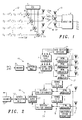
- Figure 2 shows the application of a system in accordance with Figure 1 to a time division duplex (TDD) system based on orthogonal frequency division multiplexing (OFDM) modulation, as specified for example in the Hiperlan/2 standard of the ETSI but modified to include the space-time transmit diversity system of the embodiment of the present invention shown in Figure 1.
- the embodiment of the invention shown in Figure 2 has four transmit aerials at the base station, but it is also possible for the base station to have three transmit aerials.
- the base station of the system is shown at 13 and one of a number of subscriber units is shown at 14.
- data is input to the encoder 15 where it is encoded to include error correction information.
- the resulting data train is supplied to a data-mapping and block coding unit that forms the data train into symbols and performs the negation and conjugation operations to produce the symbol blocks according to the encoding scheme 12.
- the data from the mapping and block coding unit 16 is supplied to the multipliers 8, 9, 10 and 11 where, for each sub-carrier of frequency f , it is multiplied by respective complex weighting coefficients w 1f to w 4f and applied to respective elements of an array of OFDM modulation units that feed the transmit antennas 1 to 4. It is also possible to apply interleaving of the data after the encoder 15.
- Pilot signals are included in the transmitted signals for each transmit antenna element, without weighting, to enable estimation of the downlink channels.
- a permutation signal is also added that is indicative of the number of permutations in a symbol block. For example, especially during deployment of the present invention, there may be a mix of base stations with only two transmit antenna elements and therefore two permutations per symbol block and base stations in accordance with the present invention with more than two transmit antenna elements and therefore more than two permutations per symbol block.
- the permutation signal takes a distinctive value, at least in the latter case, to enable the receiver to adapt the number of permutations performed in detecting the signal to the number made in the transmitted signal.
- the channel state information is calculated in the calculator 7 at the base station from a similar pilot signal included in the uplink transmissions from the respective subscriber unit 14 and received at the base station over the antenna elements 1, 2, 3 and 4 and detected by the receiver unit 14 of the base station; since the system is a time division duplex system with the same carrier frequencies used for the downlink and the uplink, the measurements made on the uplink pilot are considered to be a sufficient approximation to the state of the downlink signal.
- the transmitted signals are received over the array of receive antenna elements 5, which are also used for transmission of signals back to the base station.
- the received signals are demodulated in respective OFDM channel demodulators 18.
- the channel transfer coefficients are estimated by an array of channel estimators 19 from the downlink pilot signal and applied to respective receiver elements of an array 20, together with the permutation signal that indicates the number of permutations to be performed in detecting the symbols.
- the receiver elements of array 20 calculates the Hermitian transform H and H / m of the channel transfer matrix, which it uses to multiply the received signals in the array of receivers 20.
- the processed signals from the array of receivers 20 are applied to the maximum ratio combination summer 21 that adds the signals from the receiver array 20 over the antenna elements 5. Because of the transmit weights w 1 to w 4 applied at the transmitter, the detection matrix scheme is an orthogonal matrix.
- the signal from the maximum ratio combiner 21 is passed to a matrix computation unit 22 that recovers the digital signal train from the symbol blocks.
- the digital signal train is passed to a decoder 23 that applies the error correction process and recovers the data.
- the system described with reference to Figure 2 is a time division duplex system utilising orthogonal frequency division multiplexing. This enables the weighting of the transmit channels to be calculated at the base station using measurement of a pilot signal in the uplink signal transmitted from the subscriber station as an approximation for the channel state information of the downlink signal transmitted from the base station. Since the same antenna elements both at the base station and at the subscriber station are used for reception and transmission, this approximation is valid, and, indeed, the approximation is also valid in certain circumstances even where the antenna elements used for transmission and reception are not identical for the uplink and downlink.
- the system shown in Figure 3 is a frequency division duplex system based on the CDMA (code division multiple access) standards with a modification to provide some feedback information from the mobile units to the base station to provide some channel state information concerning the downlink signal.
- CDMA code division multiple access
- Such a system is compatible with the 3GPP or 3GPP2 standard if an adaptation to the standard were introduced to accommodate the channel state information fed back from the mobile unit to the base station.
- the base station comprises a transmitter part shown generally at 24 and a receiver part 25.
- Input data, together with a pilot signal and a permutation signal indicative of the number of permutations made during the space-time transmit diversity permutations is applied to the encoder 15.
- the encoder 15 includes error correction data and the resulting signal is applied to the data mapping and block coding unit 16 that assembles the train of digital data into symbol blocks with permutations, negations and conjugations according to the encoding scheme.
- Multipliers 8 to 11 then multiply the data signals by respective weights for the respective antenna elements 1, 2, 3 and 4.
- the signals are spread over different frequency sub-carrier bands before transmission by an array of spreaders 26.
- the channel state information is calculated at the mobile unit and transmitted back to the base station on the uplink over the same antenna elements as used for the downlink.
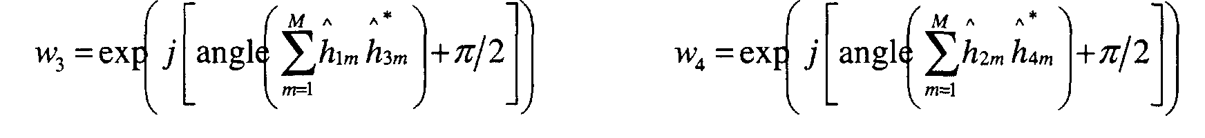
- the parameters as in equations 9 or 10 for the weights w 1 to w 4 to be applied to the multipliers 8 to 11 are calculated at the mobile unit and transmitted on the uplink to the base station, as this reduces the amount of feedback information passing over the communication link, being only a phase information for the weights w 3 and w 4 ( w 3 only in the case of three transmit antenna elements), the weights w 1 and w 2 being constant values.
- the signals received at the base station antenna elements 1 to 4 are decoded in the receiver part 25 of the base station.
- the weighting information signal is extracted by a detector 27 and supplied to the channel state calculator 7 to calculate the weights applied to the multipliers 8 to 11.
- the mobile unit comprises a receiver part indicated generally at 28 and a transmitter part 29.
- the signals transmitted are received on the antenna element array 5 and applied to a corresponding array of despreaders 30 that supply the base band signals to the array of receiver channel transfer function estimators at the mobile unit and to an array of receivers 31, each "finger" or signal received over a different transmission path being detected separately and the fingers being reassembled.
- the channel state information is calculated from a pilot signal transmitted by the base station.
- the channel state information is supplied on one hand to the mobile unit transmitter part 29 for retransmission to the base station in the uplink signal (which is at a different frequency from the downlink signal) and to the array of receiver elements 31.
- the receiver elements multiply the signals from the despreader array 30 by the coefficients of the Hermitian transform H and H / m of the channel transfer matrix obtained by permutation, transposition negation and conjugation operations on the channel state information signals, the number of permutations being defined by the received permutation signal.
- the resulting signals from each receiver antenna element are then summed over all fingers in an array of maximum ratio combiners 32 and further summed in a maximum ratio combiner 21 over the different antenna elements.
- the application of the transmit weights corresponding to equation 4 ensures that the detection matrix is an orthogonal matrix that enables the calculations to be greatly simplified.
- the symbols from the maximum ratio combiner 21 are applied to the matrix computation unit 22 and converted to a chain of digital signals and the decoder 23 detects and recovers the data with error detection.
- the transmitter part 29 of the mobile unit is similar to the transmitter part 24 of the base station in operation, and the receiver part 25 of the base station is similar to the receiver part 28 of the mobile unit.
- Adaptations are of course made to the number of antenna elements in the array 5 at the subscriber station. In this way, advantage is taken of the space-time transmit diversity performance of the present invention on the uplink from the subscriber unit to the base station as well as on the downlink from the base station to the mobile unit.
- the number of antenna elements applied at the mobile unit is reduced, for example to two antenna elements, with a view to reducing to the cost of the mobile unit.
- the spatial diversity is, of course, reduced compared to a system with four transmit antennas in the array 5.
Abstract
Description
- This invention relates to transmission of data by transmit diversity wireless communication.
- Wireless communication systems are assuming ever-increasing importance for the transmission of data, which is to be understood in its largest sense as covering speech or other sounds and images, for example, as well as abstract digital signals.
- Currently proposed standards for wireless communication systems between a stationary base station and a number of remote (mobile or immobile) stations include the 3GPP (3rd generation Partnership Project) and 3GPP2 standards, which use Frequency Division Duplex ('FDD') or Time Division Duplex ('TDD') and Code Division Multiple Access ('CDMA'). The HIPERLAN and HIPERLAN2 local area network standards of the European Telecommunications Standards Institute ('ETSI'), use Time Division Duplex ('TDD') and Orthogonal Frequency Division Multiplex ('OFDM'). The International Telecommunications Union ('ITU') IMT-2000 standards also use various multiplex techniques of these kinds. The present invention is applicable to systems of these kinds and other wireless communication systems.
- In order to improve the communication capacity of the systems while reducing the sensitivity of the systems to noise and interference and limiting the power of the transmissions, various techniques are used separately or in combination, including space diversity, where the same data is transmitted over different physical paths interleaved in time, in particular over different transmit and/or receive antenna elements, and frequency spreading where the same data is spread over different channels distinguished by their sub-carrier frequency.
- At the receiver, the detection of the symbols is performed utilising knowledge of the complex channel attenuation and phase shifts: the Channel State Information ('CSI'). The Channel State Information is obtained at the receiver by measuring the value of pilot signals transmitted together with the data from the transmitter. The knowledge of the channel enables the received signals to be processed jointly according to the Maximum Ratio Combining technique, in which the received signal is multiplied by the Hermitian transpose of the estimated channel transfer matrix.
- Two broad ways of managing the transmit diversity have been categorised as 'closed loop' and 'open loop'.
- Two closed loop methods are described in the paper entitled "Transmit adaptive array without user-specific pilot for 3G CDMA" by B. Raghothaman et al., that appeared in the IEEE Transactions 2000. In the systems described in this paper, the signals transmitted over the different transmit antenna elements of the base station are weighted according to relative weights calculated at the receiver from Channel State Information and retransmitted to the transmitter. In one system referred to, pilots specific to each user are transmitted in addition to the pilots for each transmit antenna element that are common to all users, which penalises the communication capacity of the system. In another system disclosed in the paper, user-specific pilots are avoided by re-modulating the detected signals using the measured Channel State Information and the calculated weights and using the re-modulated signals to correct errors in feedback; this imposes a heavy computational load on the receiver and the result is only reliable if the channel state estimation is sufficiently correlated with the actual channel state to avoid a high detection error rate.
- In pure 'open loop' methods, no Channel State Information is fed back to the transmitter. In such systems, the transmitter comprises a plurality of transmit antenna elements; the data is encoded in symbol blocks, the symbols of a block being permuted between the transmit antenna elements over time with respective replications and complex conjugations and/or negations. The complexity of the receiver depends on the properties of the matrix that defines this space-time block code; in particular detection is performed with a low cost in terms of simplicity of the receiver computations if this matrix is an orthogonal one.
- An open loop system using an orthogonal detection matrix is described in International Patent Application Publication N° WO 99/14871 Alamouti. In this system, the symbols of a block transmitted are permuted between the transmit antenna elements over time with respective replications and complex conjugations and/or negations according to a scheme, known as the 'Alamouti code', such that the received signal is detectable at the receiver using an orthogonal detection matrix scheme.
- The performance of the code is mainly based on the diversity order of the code. This diversity order characterizes the number of transmit and receive antennas which is actually seen by the code. For a given number of receive antenna elements, the more transmit antenna elements are used the more improvement is obtained in terms of fading and interference is obtained. However, the paper entitled "Space-Time Block Codes from Orthogonal Designs" by V. Tarokh et al. that appeared in IEEE Transactions on IT, vol. 45, July 1999, states that an orthogonal detection code matrix can not be used if the transmitter comprises more than two transmit antenna elements with full diversity without sacrificing the coding rate, that is to say the useful data rate for the user. They propose coding rates of ½ for three to eight transmit antenna elements or ¾ for three or four transmit antenna elements.
- Patent specification WO 00/51265, Whinnett et al., assigned to Motorola, describes another transmit diversity system, in which code rate is maintained for arrays of more than two transmit antenna elements but at the expense of sub-optimal transmit diversity.
- Another transmit diversity scheme (ABBA code) is described for more than two transmit antenna elements in the paper entitled "Minimal Non-Orthogonality Rate 1 Space-time Block Code for 3+ Tx Antennas" by O. Tirkkonen et al. IEEE 6th Int. Symp. On Spread-Spectrum Tech. & Appli., NJIT, pp. 429-432, Sept 2000. This coding rate 1 scheme is derived from the permutation of two Alamouti codes as described by the code matrixIt is stated that the ABBA code provides full spatial diversity to the detriment of the orthogonality of the detection matrix, which implies that the computational cost of the detection step is increased compared to an orthogonal scheme. In addition the performance of the ideal code is not fully achieved by the ABBA code due to the interference terms of the detection matrix.

- Other compromises are proposed in a paper presented by H. Jafarkhani to the IEEE Wireless Communications and Networking Conference in September 2000 with non-orthogonal detection matrices that are stated not to achieve simultaneously the optimum diversity and transmission rate, two encoding schemes proposed being of the kind described by the code matricesand


- Yet another compromise is described in the paper "A randomisation technique for non-orthogonal space-time code blocks" by A Hottinen et al. appearing in IEEE VTC 2001. However, this system still does not employ an orthogonal detection matrix with full diversity for more than two transmit antenna elements.
- Still another compromise is described in the paper "A space-time coding approach for systems employing four transmit antennas" by C. B. Papadias et al. presented at an IEEE conference in 2001 and that proposes an encoding scheme of the kindThis scheme also uses a non-orthogonal detection matrix that does not achieve simultaneously the optimum diversity and transmission rate.

- One aspect of the present invention provides a method of transmitting data from a transmitter to a remote receiver using transmit diversity wireless communication as claimed in any of claims 1 to 16.
- Another aspect of the present invention provides a system for transmitting data by a transmit diversity wireless communication method as claimed in claims 17 to 20.
- Yet another aspect of the present invention provides a transmitter for transmitting data to a remote receiver by transmit diversity wireless communication as claimed in any of claims 21 to 23.
- Still another aspect of the present invention provides a receiver for receiving data transmitted by a remote transmitter by transmit diversity wireless communication as claimed in any of claims 24 to 26.
-
- Figure 1 is a schematic diagram of a system for transmitting data by transmit diversity wireless communication in accordance with an embodiment of the invention,
- Figure 2 is a schematic diagram of a system in accordance with Figure 1 applied to a time division duplex (TDD), orthogonal frequency division multiplex (OFDM) system, and
- Figure 3 is a schematic diagram of a system in accordance with Figure 1 applied to a frequency division duplex (FDD), code division multiple access (CDMA) system
-
- Figure 1 shows a first embodiment of a system for transmitting data by a transmit diversity wireless communication network, the system comprising a first station that will be described as the transmitter side (with primary reference to its transmission function) and a second station that will be described as the receiver side (with primary reference to its reception function). In the present case, the first station and the second station are both capable of both transmission and reception and, moreover, the same antenna elements are used both for transmission and reception in the preferred embodiment of the invention.
- The transmitter side comprises four transmit antenna elements, 1, 2, 3, 4. The receiver side of the system comprises an array 5 of M receive antenna elements. The number of antenna elements 5 on the receiver side is chosen on the basis of economical considerations to provide increased channel diversity; in the case of mobile telephony, a single base station serves many hundreds or even thousands of mobile units and it is therefore more economical to add antenna elements to the base station than to the mobile units. In the case of a local area network ('LAN'), for example, the cost of the remote stations is less critical and a higher number of antennas will be chosen on the receiver side.
- Each transmit antenna element 1 to 4 transmits over a variety of paths to each of the receive antenna elements 5. Thus, considering the mth receive antenna element out of a total of M, each of the transmit antenna elements 1 to 4 transmits to the receive antenna element m over a variety of paths due to multiple reflections and scattering, which introduce complex multi-path fading; however, for simplification, the processing of the signals at the receiver is described and illustrated as if they were subject to flat fading (equivalent to transmission over a single path with no inter-path interference) that can be represented by a complex channel transfer coefficient h1m to h4m.
- In operation, symbols s1, s2, s3, s4 are derived from the data to be transmitted and applied to the transmit antennas 1, 2, 3 and 4. The receiver side of the system comprises a detector 6 which receives signals from the receive antenna element array 5 and detects the symbols s1 to s4 from the receive antenna elements.
- On the transmit side of the system, a channel state information unit extracts weights w1, w2, w3 and w4 that are, in general terms, a complex function of the channel transfer coefficients h1, h2, h 3 ,and h4 for each of the transmit antenna elements 1, 2, 3, 4. Before transmission, the signal to be transmitted from each of the antenna elements 1 to 4 is multiplied by the respective weight w1 to w4 . The weight is again a complex coefficient, which is a function of the transfer channel coefficient and hence the signal may be modified in phase and/or amplitude as a function of the channel state information.
- The data symbols to be transmitted are encoded in symbol blocks and the symbols are permuted over time within each block between the transmit antenna elements 1 to 4 with respective replications and complex conjugations and/or negations, so that the received signal is detectable at the receiver side using an orthogonal detection matrix scheme. The encoding scheme matrix for the symbol blocks is shown at 8 in Figure 1.
- The symbols s1 to s4 are permuted over the transmit antenna elements a number of times which is a power of 2, the power being greater than or equal to 2, the block comprising four permutations in the present case. It is also possible for the transmitter to include three antenna elements, the block of symbols preferably comprising four permutations in this case also. A higher number of permutations may also be utilised but will prolong the symbol block transmission.
- As shown in Figure 1, the symbols within each block are permuted in pairs within respective subsets of the symbols and transmitted over corresponding subsets of the transmit antenna elements 1 to 4, the subsets of symbols subsequently being permuted between the subsets of the transmit antenna elements. Thus, as shown in Figure 1, symbols s1, s2 are transmitted initially over transmit antenna elements 1, 2 and symbols s3, s4 are transmitted initially over transmit antenna elements 3, 4. In the next step, the negation and conjugation of the symbol s2 is transmitted over the transmit antenna element 1 and the conjugation of the symbol s1 is transmitted over the transmit antenna element 2, the negation and conjugation of the symbol s4 being transmitted over the transmit antenna element 3 and the conjugation of the symbol s3 being transmitted over the transmit antenna element 4. It will be understood that the symbols s1 and s2 and their negations and/or their conjugations constitute a first subset of symbols that is transmitted over the subset of transmit antenna elements 1 and 2 with permutations and the symbols s3 and s4 with their negations and/or conjugations are transmitted over the subset of transmit antenna elements 3 and 4 with permutations. In the next step, the subset including symbols s3 and s4 is transmitted over the subset of transmit antenna elements 1 and 2 with permutations while the subset of symbols s1, s2 is transmitted over the subset of transmit antenna elements 3 and 4 with permutations.
- This encoding scheme is a scheme of the kind ABBA. This embodiment of the present invention enables this encoding scheme to be decoded by an orthogonal detection matrix scheme at the receiver. It is also possible for other encoding schemes of analogous nature to be decoded using an orthogonal detection matrix scheme, for instance ABB*-A*, or AB-B*A*. Moreover, the space-time code has an overall coding rate of one (that is to say that the data rate is as high as in a single antenna case) and the system derives full benefit from the spatial diversity of the multiple transmit and receive antenna elements at the transmitter and receiver. The fact that the detection scheme uses an orthogonal matrix enables the detection to be performed with low computational cost. Interference terms that would be present with a non-orthogonal detection matrix scheme are substantially cancelled out by the application of the weights w1 to w4 to the signals transmitted as a function of the estimated channel transfer functions.
- The signal Ym received by the mth antenna over four time instants within the symbol block can be written aswhere ym,1 to ym,4 represent the signals received from the transmit antenna elements 1 to 4 respectively, Hm represents the matrix obtained by multiplying the channel transfer functions by the corresponding weights applied to the transmit antenna elements, S represents the symbols s1 to s4 transmitted from the transmit antenna elements 1 to 4 respectively, bm,1 to bm,4 represent the noise and interference at the mth receive antenna element and Bm represents the received noise matrix. In this equation, the minus sign represents the negation of the corresponding value and the asterisk sign represents the conjugate of the value.

- These multiple received signals are processed at the receiver according to the Maximum Ratio Combining technique. That is to say, the received pilot signals for each transmit antenna element are measured in order to estimate the channel transfer coefficients h1m to h4m and the weights applied at the transmitter side w1 to w4 and the Hermitian transposes H and H / m of the estimated channel transfer coefficient matrices for each receive antenna element m are calculated. The received symbol blocks Ym are multiplied by the corresponding Hermitian transposes H and H / m and the resulting multiplied signals are summed over the antennas, and we finally get a new signal Z such that

- Provided that the channel estimation is sufficently accurate and the weights actually applied to the signals to be transmitted also correspond accurately to the calculated weights, the resulting detection matrixcorresponds with a sufficient degree of approximation to the detection matrix of the ideal orthogonal rate 1 code scheme for proper detection of the data, that is to say
 if the transmit weights satisfy at least approximately the following relation:
 where hnm is the channel transfer coefficient of the channel between the nth transmit antenna element and the mth receive antenna element, wn is the weight applied to the signal of the nth transmit antenna element and
 represents the real part of the value on which it operates.
- Due to the orthogonality of the code scheme, the detection step can then be performed with a low computational cost.
- Several sets of transmit weights may be used to solve this equation in accordance with this embodiment of the present invention. One example consists in choosing the four weights such that


- With this choice of weights, it is sufficient for the transmitting side to obtain phase information for the weighting operation on two out of the four transmit antenna elements, which reduces the amount of feedback information to be transmitted from the receiver side if the channel state information is measured at the receiver side, for example.
- The detection scheme for three emitting antennas can easily be derived from this four antenna coding scheme. Four complex symbols are transmitted from three antennas over four time instants, for instance by turning off the 4th antenna, which corresponds to set h 4 m = 0 in the previous equations. In this case the overall space-time scheme is an orthogonal one if and only if the transmit weights satisfy:for instance by choosing


- With this choice of weights, it is sufficient for the transmitting side to obtain phase information the weighting operation on one only out of the three transmit antenna elements.
- The above conditions for the weighting scheme to enable decoding by an orthogonal detection matrix are applicable to an encoding scheme of the kind 'ABBA', that is to say where sub-sets A and B of symbols s1, s2 and s3, s4 and conjugated symbols s1*, s2* and s3*, s4* and/or negated conjugated symbols -s1*, -s2 * and -s3*, -s4* symbols are permuted over time between sub-sets 1, 2 and 3, 4 of antenna elements without negation nor conjugation of the symbol sub-sets, according to the matrix

- Other encoding schemes may be utilised of the formor
 In the absence of weighting before transmission, these encoding schemes would leave interference terms that would require a detection matrix
 that is non-orthogonal.
In order to be able to detect the signals using an orthogonal detection matrix, in accordance with another embodiment of the present invention the weightings applied to the signals to be transmitted are derived such that
- In a preferred realisation of this embodiment,

- In accordance with yet other embodiments of the present invention, in equation 8,where
 represents the imaginary part of the value it operates and the scheme is decodable using an orthogonal detection matrix.
- Preferably,

- Figure 2 shows the application of a system in accordance with Figure 1 to a time division duplex (TDD) system based on orthogonal frequency division multiplexing (OFDM) modulation, as specified for example in the Hiperlan/2 standard of the ETSI but modified to include the space-time transmit diversity system of the embodiment of the present invention shown in Figure 1. The embodiment of the invention shown in Figure 2 has four transmit aerials at the base station, but it is also possible for the base station to have three transmit aerials. The base station of the system is shown at 13 and one of a number of subscriber units is shown at 14.
- At the base station 13, data is input to the encoder 15 where it is encoded to include error correction information. The resulting data train is supplied to a data-mapping and block coding unit that forms the data train into symbols and performs the negation and conjugation operations to produce the symbol blocks according to the encoding scheme 12. The data from the mapping and block coding unit 16 is supplied to the multipliers 8, 9, 10 and 11 where, for each sub-carrier of frequency f, it is multiplied by respective complex weighting coefficients w1f to w4f and applied to respective elements of an array of OFDM modulation units that feed the transmit antennas 1 to 4. It is also possible to apply interleaving of the data after the encoder 15.
- Pilot signals are included in the transmitted signals for each transmit antenna element, without weighting, to enable estimation of the downlink channels. A permutation signal is also added that is indicative of the number of permutations in a symbol block. For example, especially during deployment of the present invention, there may be a mix of base stations with only two transmit antenna elements and therefore two permutations per symbol block and base stations in accordance with the present invention with more than two transmit antenna elements and therefore more than two permutations per symbol block. The permutation signal takes a distinctive value, at least in the latter case, to enable the receiver to adapt the number of permutations performed in detecting the signal to the number made in the transmitted signal.
- The channel state information is calculated in the calculator 7 at the base station from a similar pilot signal included in the uplink transmissions from the respective subscriber unit 14 and received at the base station over the antenna elements 1, 2, 3 and 4 and detected by the receiver unit 14 of the base station; since the system is a time division duplex system with the same carrier frequencies used for the downlink and the uplink, the measurements made on the uplink pilot are considered to be a sufficient approximation to the state of the downlink signal.
- At the subscriber unit 14, the transmitted signals are received over the array of receive antenna elements 5, which are also used for transmission of signals back to the base station. The received signals are demodulated in respective OFDM channel demodulators 18. The channel transfer coefficients are estimated by an array of channel estimators 19 from the downlink pilot signal and applied to respective receiver elements of an array 20, together with the permutation signal that indicates the number of permutations to be performed in detecting the symbols. The receiver elements of array 20 calculates the Hermitian transform H and H / m of the channel transfer matrix, which it uses to multiply the received signals in the array of receivers 20.
- The processed signals from the array of receivers 20 are applied to the maximum ratio combination summer 21 that adds the signals from the receiver array 20 over the antenna elements 5. Because of the transmit weights w1 to w4 applied at the transmitter, the detection matrix scheme is an orthogonal matrix. The signal from the maximum ratio combiner 21 is passed to a matrix computation unit 22 that recovers the digital signal train from the symbol blocks. The digital signal train is passed to a decoder 23 that applies the error correction process and recovers the data.
- The system described with reference to Figure 2 is a time division duplex system utilising orthogonal frequency division multiplexing. This enables the weighting of the transmit channels to be calculated at the base station using measurement of a pilot signal in the uplink signal transmitted from the subscriber station as an approximation for the channel state information of the downlink signal transmitted from the base station. Since the same antenna elements both at the base station and at the subscriber station are used for reception and transmission, this approximation is valid, and, indeed, the approximation is also valid in certain circumstances even where the antenna elements used for transmission and reception are not identical for the uplink and downlink.
- The system shown in Figure 3 is a frequency division duplex system based on the CDMA (code division multiple access) standards with a modification to provide some feedback information from the mobile units to the base station to provide some channel state information concerning the downlink signal. Such a system is compatible with the 3GPP or 3GPP2 standard if an adaptation to the standard were introduced to accommodate the channel state information fed back from the mobile unit to the base station.
- Referring now to Figure 3 in more detail, the base station comprises a transmitter part shown generally at 24 and a receiver part 25. Input data, together with a pilot signal and a permutation signal indicative of the number of permutations made during the space-time transmit diversity permutations is applied to the encoder 15. The encoder 15 includes error correction data and the resulting signal is applied to the data mapping and block coding unit 16 that assembles the train of digital data into symbol blocks with permutations, negations and conjugations according to the encoding scheme. Multipliers 8 to 11 then multiply the data signals by respective weights for the respective antenna elements 1, 2, 3 and 4. In accordance with the CDMA specifications, the signals are spread over different frequency sub-carrier bands before transmission by an array of spreaders 26.
- In the present embodiment of the invention, the channel state information is calculated at the mobile unit and transmitted back to the base station on the uplink over the same antenna elements as used for the downlink. In the preferred embodiment, the parameters as in equations 9 or 10 for the weights w1 to w4 to be applied to the multipliers 8 to 11 are calculated at the mobile unit and transmitted on the uplink to the base station, as this reduces the amount of feedback information passing over the communication link, being only a phase information for the weights w3 and w4 (w3 only in the case of three transmit antenna elements), the weights w1 and w2 being constant values. The signals received at the base station antenna elements 1 to 4 are decoded in the receiver part 25 of the base station. The weighting information signal is extracted by a detector 27 and supplied to the channel state calculator 7 to calculate the weights applied to the multipliers 8 to 11.
- The mobile unit comprises a receiver part indicated generally at 28 and a transmitter part 29. At the mobile unit, the signals transmitted are received on the antenna element array 5 and applied to a corresponding array of despreaders 30 that supply the base band signals to the array of receiver channel transfer function estimators at the mobile unit and to an array of receivers 31, each "finger" or signal received over a different transmission path being detected separately and the fingers being reassembled. The channel state information is calculated from a pilot signal transmitted by the base station. The channel state information is supplied on one hand to the mobile unit transmitter part 29 for retransmission to the base station in the uplink signal (which is at a different frequency from the downlink signal) and to the array of receiver elements 31.
- The receiver elements multiply the signals from the despreader array 30 by the coefficients of the Hermitian transform H and H / m of the channel transfer matrix obtained by permutation, transposition negation and conjugation operations on the channel state information signals, the number of permutations being defined by the received permutation signal. The resulting signals from each receiver antenna element are then summed over all fingers in an array of maximum ratio combiners 32 and further summed in a maximum ratio combiner 21 over the different antenna elements. Once again, the application of the transmit weights corresponding to equation 4 ensures that the detection matrix is an orthogonal matrix that enables the calculations to be greatly simplified. The symbols from the maximum ratio combiner 21 are applied to the matrix computation unit 22 and converted to a chain of digital signals and the decoder 23 detects and recovers the data with error detection.
- In a preferred embodiment of this type of system, the transmitter part 29 of the mobile unit is similar to the transmitter part 24 of the base station in operation, and the receiver part 25 of the base station is similar to the receiver part 28 of the mobile unit. Adaptations are of course made to the number of antenna elements in the array 5 at the subscriber station. In this way, advantage is taken of the space-time transmit diversity performance of the present invention on the uplink from the subscriber unit to the base station as well as on the downlink from the base station to the mobile unit.
- In another embodiment of the invention, the number of antenna elements applied at the mobile unit is reduced, for example to two antenna elements, with a view to reducing to the cost of the mobile unit. In this case, the spatial diversity is, of course, reduced compared to a system with four transmit antennas in the array 5.
Claims (26)
- A method of transmitting data from a transmitter (13, 24) to a remote receiver (14, 28) using transmit diversity wireless communication, said transmitter comprising a plurality of transmit antenna elements (1, 2, 3, 4), the method comprising encoding said data in symbol blocks (12), the symbols (s1 , s2 , s3 , s4 ) of a block being permuted between said transmit antenna elements (1, 2, 3, 4) over time with respective replications and complex conjugations and/or negations,
characterised in that said transmitter (13, 24) comprises at least three of said transmit antenna elements (1, 2, 3, 4) and said method comprises modifying signals to be transmitted over at least one of said transmit antenna elements (1, 2, 3, 4) as a function of channel information at least approximately related to the channel transfer function of the transmitted signals (h1, h2, h3,and h4 ), so that the received signal is detectable at the receiver using an orthogonal detection matrix scheme. - A method as claimed in claim 1, characterised in that said signals transmitted over said transmit antenna elements (1, 2, 3, 4) are modified in phase as a function of said channel information.
- A method as claimed in claim 1 or 2, characterised in that said channel information is a function of signals received at said receiver (14, 28) from said transmitter (13, 24) and is transmitted from said receiver to said transmitter.
- A method as claimed in claim 1 or 2, wherein said receiver (14, 28) additionally comprises transmitting means (13, 29) for transmitting signals over channels similar to the transmit channels of said transmitter (13, 24), and said transmitter (13, 24) additionally comprises receiving means (14, 25) including said transmit antenna elements (1, 2, 3, 4) for receiving signals transmitted from said transmitting means (13, 29), characterised in that said channel information is calculated at said transmitter (13, 24) as a function of the channel transfer function of signals transmitted from said transmitting means (13, 29) to said receiving means (14, 25).
- A method as claimed in any preceding claim, characterised in that said symbols (s1, s2, s3, s4 ) are permuted over time within said block (12) between the transmit antenna elements (1, 2, 3, 4) a number of times equal to a power of two, which power is greater than or equal to two.
- A method as claimed in claim 4, characterised in that said transmitter (13, 24) comprises three or four of said transmit antenna elements (1, 2, 3, 4) and said symbols (s1 , s2 , s3, s4 ) are permuted over time within said block (12) four times between the transmit antenna elements (1, 2, 3, 4).
- A method as claimed in any preceding claim, characterised in that pairs of symbols (s1 , s2 ; s3 , s4 ) within said block (12) are permuted over time within respective sub-sets of symbols and permuted symbols between the transmit antenna elements (1, 2; 3, 4) of respective sub-sets of transmit antenna elements and said sub-sets of symbols and permuted symbols are permuted over time between said sub-sets of transmit antenna elements.
- A method as claimed in claim 7, characterised in that said sub-sets of symbols and permuted symbols are permuted over time between said sub-sets of transmit antenna elements (1, 2, 3, 4) without conjugation or negation and said signals transmitted over at least one of said transmit antenna elements (1, 2, 3, 4) are modified so as to satisfy at least approximately the equationwhere the complex numbers h1m, h2m, h3m and h4m represent the actual channel transfer functions over the transmit antenna elements (1, 2, 3, and 4) and the mth receiver transmit antenna element, the complex numbers w1, w2, w3 and w4 represent the modifications applied to the signals at the transmit antenna elements (1, 2, 3, and 4), x* represents the complex conjugate of the number x and the operator
 represents the real part of a complex value.
- A method as claimed in claim 7, characterised in that said signals transmitted over at least one of said transmit antenna elements (1, 2, 3, 4) are modified so as to satisfy at least approximately the equationor the equation
 where the complex number hn,m represents the actual channel transfer function over the nth transmit antenna element and the mth receiver transmit antenna element, the complex number wn represents the modification applied to the signals at the nth transmit antenna element, x* represents the complex conjugate of the number x,

- A method as claimed in claim 7 or 8, characterised in that said transmitter (13, 24) comprises four of said transmit antenna elements (1, 2, 3, 4) and said signals transmitted over said transmit antenna elements (1, 2, 3, 4) are modified so as to satisfy at least approximately the equationswhere the complex number h andn , m represents the measured channel transfer function over the nth transmit antenna element and the mth receiver antenna element, M represents the total number of receiver antenna elements at said receiver, the complex number wn represents the modification applied to the signals at the nth transmit antenna element and x* represents the complex conjugate of the number x.
- A method as claimed in claim 10, characterised in that values at least approximately related to w 3 and w 4 are calculated at said receiver (14, 28) as a function of received signals and transmitted from said receiver (14, 28) to said transmitter (13, 24).
- A method as claimed in claim 10, wherein said receiver (14, 28) additionally comprises transmitting means (13, 29) for transmitting signals over channels similar to the transmit channels of said transmitter (13, 24), and said transmitter (13, 24) additionally comprises receiving means (14, 25) including said transmit antenna elements (1, 2, 3, 4) for receiving signals transmitted from said transmitting means (13, 29), characterised in that values at least approximately related to w 3 and w 4 are calculated at said transmitter (13, 24) as a function of the channel transfer function (h1, h2, h 3,and h4 ) of signals transmitted from said transmitting means (13, 29) to said receiving means (14, 25).
- A method as claimed in claim 7 or 8, characterised in that said transmitter (13, 24) comprises three of said transmit antenna elements (1, 2, 3, 4) and said signals transmitted over said transmit antenna elements (1, 2, 3, 4) are modified so as to satisfy at least approximately the equationswhere the complex number h andn,m represents the measured channel transfer function over the nth transmit antenna element and the mth receiver antenna element, M represents the total number of receiver antenna elements at said receiver, the complex number wn represents the modification applied to the signals at the nth transmit antenna element and x* represents the complex conjugate of the number x.

- A method as claimed in claim 13, characterised in that a value at least approximately related to w 3 is calculated at said receiver (14, 28) as a function of received signals and transmitted from said receiver (14, 28) to said transmitter (13, 24).
- A method as claimed in claim 13, wherein said receiver (14, 28) additionally comprises transmitting means (13, 29) for transmitting signals over channels similar to the transmit channels of said transmitter (13, 24), and said transmitter (13, 24) additionally comprises receiving means (14, 25) including said transmit antenna elements (1, 2, 3, 4) for receiving signals transmitted from said transmitting means (13, 29), characterised in that a value at least approximately related to w 3 is calculated at said transmitter (13, 24) as a function of the channel transfer function (h1, h2, h 3,and h4 ) of signals transmitted from said transmitting means (13, 29) to said receiving means (14, 25).
- A method as claimed in any preceding claim, characterised in that a permutation signal indicative of the number of permutations over time of said symbols (s1, s2, s3, s4 ) within said block is transmitted from said transmitter (13, 24) to said receiver (14, 28) and said receiver (14, 28) is responsive to said permutation signal in the numbers of permutations it performs in detecting the data transmitted.
- A system for transmitting data by a transmit diversity wireless communication method as claimed in any preceding claim, the system comprising said transmitter (13, 24) and a plurality of said remote receivers (14, 28)
characterised in that said transmitter (13, 24) comprises at least three of said transmit antenna elements (1, 2, 3, 4) and transmit encoding means (15, 16, 8, 9, 10, 11) for encoding said data in symbol blocks (12), the symbols of a block (12) being permuted between said transmit antenna elements (1, 2, 3, 4) over time with respective replications and complex conjugations and/or negations, so that the received signal is detectable at the receiver (14, 28) using an orthogonal detection matrix scheme, said transmit encoding means (15, 16, 8, 9, 10, 11) being arranged to modify signals transmitted over at least one of said transmit antenna elements (1, 2, 3, 4) as a function of channel information at least approximately related to the channel transfer function (h1, h2, h 3 ,and h4 ) of the transmitted signals. - A system as claimed in claim 17, characterised in that said receiver (14, 28) comprises means for calculating said channel information as a function of pilot signals received from said transmitter (13, 24) and for transmitting said channel information from said receiver (14, 28) to said transmitter (13, 24).
- A system as claimed in claim 17, wherein said receiver (14, 28) additionally comprises transmitting means (13, 29) for transmitting signals over channels similar to the transmit channels of said transmitter (13, 24), and said transmitter (13, 24) additionally comprises receiving means (14, 25) including said transmit antenna elements (1, 2, 3, 4) for receiving signals transmitted from said transmitting means (13, 29), characterised in that said transmit encoding means (15, 16, 8, 9, 10, 11) at said transmitter (13, 24) is responsive to the channel transfer function of pilot signals transmitted from said transmitting means (13, 29) to said receiving means (14, 25) to calculate said channel information.
- A system as claimed in any of claims 17 to 19, characterised in that said encoding means (15, 16, 8, 9, 10, 11) is arranged to transmit a permutation signal indicative of the number of permutations over time of said symbols within said block and said receiver comprises detection means responsive to said permutation signal in the number of permutations it performs in detecting the data transmitted.
- A transmitter for transmitting data to a remote receiver by a transmit diversity wireless communication method as claimed in any of claims 1 to 16,
characterised in that said transmitter (13, 24) comprises at least three of said transmit antenna elements (1, 2, 3, 4) and transmit encoding means (15, 16, 8, 9, 10, 11) for encoding said data in symbol blocks (12), the symbols (s1, s2, s3, s4 ) of a block (12) being permuted between said transmit antenna elements (1, 2, 3, 4) over time with respective replications and complex conjugations and/or negations, so that the received signal is detectable at the receiver (14, 28) using an orthogonal detection matrix scheme, said transmit encoding means (15, 16, 8, 9, 10, 11) being arranged to modify signals transmitted over at least one of said transmit antenna elements (1, 2, 3, 4) as a function of channel information at least approximately related to the channel transfer function (h1, h2, h3 ,and h4 ) of the transmitted signals. - A transmitter as claimed in claim 21, for transmitting data to a receiver additionally comprising transmitting means (13, 29) for transmitting signals over channels similar to the transmit channels of said transmitter (13, 24), characterised in that said transmitter (13, 24) additionally comprises receiving means (14, 25) including said transmit antenna elements (1, 2, 3, 4) for receiving signals transmitted from said transmitting means (13, 29), said transmit encoding means (15, 16, 8, 9, 10, 11) at said transmitter (13, 24) being responsive to the channel transfer function (h1, h2, h 3 ,and h4 ) of signals transmitted from said transmitting means (13, 29) to said receiving means (14, 25) to calculate said channel information.
- A transmitter as claimed in any of claims 21 or 22, characterised in that said encoding means (15, 16, 8, 9, 10, 11) is arranged to transmit a permutation signal indicative of the number of permutations over time of said symbols within said block.
- A receiver for receiving data transmitted by a transmit diversity wireless communication method as claimed in any of claims 1 to 16 from a transmitter (13, 24) comprising at least three of said transmit antenna elements (1, 2, 3, 4),
characterised in that said receiver (14, 28) comprises detection means (19, 20, 21, 31, 32) for detecting data encoded in symbol blocks (12), the symbols (s1, s2, s3, s4 ) of a block (12) having been permuted between said transmit antenna elements (1, 2, 3, 4) over time with respective replications and complex conjugations and/or negations, so that the received signal is detectable at the receiver (14, 28) using an orthogonal detection matrix scheme, said signals transmitted over at least one of said transmit antenna elements (1, 2, 3, 4) having been modified as a function of channel information at least approximately related to the channel transfer function (h1, h2, h 3 ,and h4 ) of the transmitted signals. - A receiver as claimed in claim 24, characterised in that said detection means (19, 20, 21, 31, 32) at said receiver (14, 28) comprises means (19) for calculating said channel information as a function of signals received from said transmitter (13, 24) and for transmitting said channel information from said receiver (14, 28) to said transmitter (13, 24).
- A receiver as claimed in claim 24 or 25, characterised in that said detection means (19, 20, 21, 31, 32) is responsive to a permutation signal indicative of the number of permutations over time of said symbols within said block, and which is transmitted from said transmitter to said receiver, in the nmbers of permutations it performs in detecting the data transmitted.
Priority Applications (8)
| Application Number | Priority Date | Filing Date | Title |
|---|---|---|---|
| DE60134641T DE60134641D1 (en) | 2001-08-13 | 2001-08-13 | Wireless communication with broadcasting diversity |
| EP01402162A EP1284545B1 (en) | 2001-08-13 | 2001-08-13 | Transmit diversity wireless communication |
| AT01402162T ATE400097T1 (en) | 2001-08-13 | 2001-08-13 | WIRELESS COMMUNICATION WITH TRANSMIT DIVERSITY |
| CN02815852A CN100581076C (en) | 2001-08-13 | 2002-07-29 | Transmit diversity wireless communication method and system |
| PCT/EP2002/008423 WO2003017528A1 (en) | 2001-08-13 | 2002-07-29 | Transmit diversity wireless communication |
| KR1020047002225A KR100926643B1 (en) | 2001-08-13 | 2002-07-29 | Transmit diversity wireless communication |
| US10/486,474 US7308035B2 (en) | 2001-08-13 | 2002-07-29 | Transit diversity wireless communication |
| EP02754951A EP1417780A1 (en) | 2001-08-13 | 2002-07-29 | Transmit diversity wireless communication |
Applications Claiming Priority (1)
| Application Number | Priority Date | Filing Date | Title |
|---|---|---|---|
| EP01402162A EP1284545B1 (en) | 2001-08-13 | 2001-08-13 | Transmit diversity wireless communication |
Publications (2)
| Publication Number | Publication Date |
|---|---|
| EP1284545A1 true EP1284545A1 (en) | 2003-02-19 |
| EP1284545B1 EP1284545B1 (en) | 2008-07-02 |
Family
ID=8182850
Family Applications (2)
| Application Number | Title | Priority Date | Filing Date |
|---|---|---|---|
| EP01402162A Expired - Lifetime EP1284545B1 (en) | 2001-08-13 | 2001-08-13 | Transmit diversity wireless communication |
| EP02754951A Withdrawn EP1417780A1 (en) | 2001-08-13 | 2002-07-29 | Transmit diversity wireless communication |
Family Applications After (1)
| Application Number | Title | Priority Date | Filing Date |
|---|---|---|---|
| EP02754951A Withdrawn EP1417780A1 (en) | 2001-08-13 | 2002-07-29 | Transmit diversity wireless communication |
Country Status (7)
| Country | Link |
|---|---|
| US (1) | US7308035B2 (en) |
| EP (2) | EP1284545B1 (en) |
| KR (1) | KR100926643B1 (en) |
| CN (1) | CN100581076C (en) |
| AT (1) | ATE400097T1 (en) |
| DE (1) | DE60134641D1 (en) |
| WO (1) | WO2003017528A1 (en) |
Cited By (43)
| Publication number | Priority date | Publication date | Assignee | Title |
|---|---|---|---|---|
| EP1503520A2 (en) | 2003-07-26 | 2005-02-02 | Samsung Electronics Co., Ltd. | System and method for transmitting/receiving a signal in a mobile communication system using a multiple input multiple output adaptive antenna array scheme |
| US7272359B2 (en) | 2004-01-26 | 2007-09-18 | Magnolia Broadband Inc. | Communicating signals according to a quality indicator using multiple antenna elements |
| EP1843484A1 (en) * | 2006-04-03 | 2007-10-10 | Nokia Siemens Networks Gmbh & Co. Kg | Method for data transmission in a radio communication system as well as radio station and radio communications system |
| CN100344076C (en) * | 2003-05-29 | 2007-10-17 | 三星电子株式会社 | Apparatus and method for transmitting/receiving data using a multiple antenna diversity scheme |
| US7321636B2 (en) | 2001-05-31 | 2008-01-22 | Magnolia Broadband Inc. | Communication device with smart antenna using a quality-indication signal |
| WO2008077090A2 (en) * | 2006-12-19 | 2008-06-26 | Qualcomm Incorporated | Beamspace-time coding based on channel quality feedback |
| US7418067B1 (en) | 2003-04-14 | 2008-08-26 | Magnolia Broadband Inc. | Processing diversity signals at a mobile device using phase adjustments |
| US7430430B2 (en) | 2003-12-16 | 2008-09-30 | Magnolia Broadband Inc. | Adjusting a signal at a diversity system |
| US7505741B2 (en) | 2002-11-01 | 2009-03-17 | Magnolia Broadband Inc. | Processing diversity signals using a delay |
| US7515877B2 (en) | 2004-11-04 | 2009-04-07 | Magnolia Broadband Inc. | Communicating signals according to a quality indicator and a time boundary indicator |
| WO2009048362A1 (en) * | 2007-10-12 | 2009-04-16 | Telefonaktiebolaget Lm Ericsson (Publ) | Method and apparatus for per-antenna pilot transmission supporting multi-user mimo transmission |
| US7558591B2 (en) | 2004-10-12 | 2009-07-07 | Magnolia Broadband Inc. | Determining a power control group boundary of a power control group |
| US7616930B2 (en) | 2005-05-24 | 2009-11-10 | Magnolia Broadband Inc. | Determining a phase adjustment in accordance with power trends |
| US7630445B1 (en) | 2005-10-25 | 2009-12-08 | Magnolia Broadband Inc. | Establishing slot boundaries of slots of a diversity control feedback signal |
| US7633905B1 (en) | 2005-09-02 | 2009-12-15 | Magnolia Broadband Inc. | Calibrating a transmit diversity communication device |
| US7663545B2 (en) | 2006-12-26 | 2010-02-16 | Magnolia Broadband Inc. | Method, system and apparatus for determining antenna weighting for transmit diversity |
| US7746946B2 (en) | 2005-10-10 | 2010-06-29 | Magnolia Broadband Inc. | Performing a scan of diversity parameter differences |
| US7783267B1 (en) | 2005-06-23 | 2010-08-24 | Magnolia Broadband Inc. | Modifying a signal in response to quality indicator availability |
| US7796717B2 (en) | 2005-11-02 | 2010-09-14 | Magnolia Brandband Inc. | Modifying a signal according to a diversity parameter adjustment |
| US7835702B1 (en) | 2005-09-15 | 2010-11-16 | Magnolia Broadband Inc. | Calculating a diversity parameter adjustment according to previously applied diversity parameter adjustments |
| US7869535B2 (en) | 2007-02-28 | 2011-01-11 | Magnolia Broadband Inc. | Method, system and apparatus for phase control of transmit diversity signals |
| US7945222B2 (en) | 2007-03-14 | 2011-05-17 | Magnolia Broadband Inc. | Method, apparatus and system for providing transmit diversity feedback |
| US7949069B2 (en) | 2006-10-26 | 2011-05-24 | Magnolia Broadband Inc. | Method, system and apparatus for applying hybrid ARQ to the control of transmit diversity |
| US7965987B2 (en) | 2005-11-03 | 2011-06-21 | Magnolia Broadband Inc. | Amplifying a transmit signal using a fractional power amplifier |
| US7991365B2 (en) | 2007-03-01 | 2011-08-02 | Magnolia Broadband Inc. | Method, system and apparatus for estimation of propagation path variability of a transmit diversity channel |
| US8014734B2 (en) | 2007-03-15 | 2011-09-06 | Magnolia Broadband Inc. | Method, apparatus and system for controlling a transmit diversity device |
| US8027374B2 (en) | 2006-12-27 | 2011-09-27 | Magnolia Broadband Inc. | Method, system and apparatus for transmit diversity control |
| US8032092B2 (en) | 2007-12-06 | 2011-10-04 | Magnolia Broadband Inc. | System, apparatus and method for introducing antenna pattern variability |
| US8032091B2 (en) | 2007-03-14 | 2011-10-04 | Magnolia Broadband Inc. | Method, apparatus and system for providing transmit diversity feedback during soft handoff |
| US8036603B2 (en) | 2007-03-15 | 2011-10-11 | Magnolia Broadband Inc. | Method, apparatus and system for providing feedback to a transmit diversity device |
| US8046017B2 (en) | 2007-03-15 | 2011-10-25 | Magnolia Broadband Inc. | Method and apparatus for random access channel probe initialization using transmit diversity |
| US8150441B2 (en) | 2006-11-06 | 2012-04-03 | Magnolia Broadband Inc. | Modifying a signal by controlling transmit diversity parameters |
| US8199735B2 (en) | 2006-12-12 | 2012-06-12 | Google Inc. | Method, system and apparatus for the control of transmit diversity |
| US8249187B2 (en) | 2002-05-09 | 2012-08-21 | Google Inc. | System, method and apparatus for mobile transmit diversity using symmetric phase difference |
| US8442457B2 (en) | 2009-09-08 | 2013-05-14 | Google Inc. | System and method for adaptive beamforming for specific absorption rate control |
| US8630595B2 (en) | 2007-03-01 | 2014-01-14 | Google Inc. | System, method and apparatus for transmit diversity control based on variations in propagation path |
| US8699968B2 (en) | 2007-03-14 | 2014-04-15 | Google Inc. | Using multiple and a single feedback for UE uplink beamforming in soft handoff |
| US8731489B2 (en) | 2007-03-15 | 2014-05-20 | Google Inc. | Method and apparatus for random access channel probe initialization using transmit diversity |
| US8750811B2 (en) | 2007-03-14 | 2014-06-10 | Google Inc. | Method, apparatus and system for phase difference adjustment in transmit diversity |
| WO2014138646A1 (en) * | 2013-03-07 | 2014-09-12 | Qualcomm Incorporated | Voltage mode driver circuit for n-phase systems |
| US8849222B2 (en) | 2011-02-16 | 2014-09-30 | Google Inc. | Method and device for phase adjustment based on closed-loop diversity feedback |
| US8958757B2 (en) | 2010-05-10 | 2015-02-17 | Google Inc. | System, method and apparatus for mobile transmit diversity using symmetric phase difference |
| US9048913B2 (en) | 2010-07-06 | 2015-06-02 | Google Inc. | Method and apparatus for adaptive control of transmit diversity to provide operating power reduction |
Families Citing this family (37)
| Publication number | Priority date | Publication date | Assignee | Title |
|---|---|---|---|---|
| US20040008648A1 (en) * | 2002-07-11 | 2004-01-15 | Schmidl Timothy M. | Diversity decisions for downlink antenna transmission |
| US8194770B2 (en) | 2002-08-27 | 2012-06-05 | Qualcomm Incorporated | Coded MIMO systems with selective channel inversion applied per eigenmode |
| JP4318510B2 (en) * | 2002-08-28 | 2009-08-26 | パナソニック株式会社 | Communication apparatus and communication method |
| JP3679075B2 (en) | 2002-09-13 | 2005-08-03 | 松下電器産業株式会社 | Radio transmission apparatus and radio transmission method |
| US8218609B2 (en) | 2002-10-25 | 2012-07-10 | Qualcomm Incorporated | Closed-loop rate control for a multi-channel communication system |
| US7002900B2 (en) * | 2002-10-25 | 2006-02-21 | Qualcomm Incorporated | Transmit diversity processing for a multi-antenna communication system |
| US8570988B2 (en) | 2002-10-25 | 2013-10-29 | Qualcomm Incorporated | Channel calibration for a time division duplexed communication system |
| US20040081131A1 (en) | 2002-10-25 | 2004-04-29 | Walton Jay Rod | OFDM communication system with multiple OFDM symbol sizes |
| US8134976B2 (en) | 2002-10-25 | 2012-03-13 | Qualcomm Incorporated | Channel calibration for a time division duplexed communication system |
| US8208364B2 (en) | 2002-10-25 | 2012-06-26 | Qualcomm Incorporated | MIMO system with multiple spatial multiplexing modes |
| US7986742B2 (en) | 2002-10-25 | 2011-07-26 | Qualcomm Incorporated | Pilots for MIMO communication system |
| US8170513B2 (en) | 2002-10-25 | 2012-05-01 | Qualcomm Incorporated | Data detection and demodulation for wireless communication systems |
| US8169944B2 (en) | 2002-10-25 | 2012-05-01 | Qualcomm Incorporated | Random access for wireless multiple-access communication systems |
| US8320301B2 (en) | 2002-10-25 | 2012-11-27 | Qualcomm Incorporated | MIMO WLAN system |
| US7324429B2 (en) | 2002-10-25 | 2008-01-29 | Qualcomm, Incorporated | Multi-mode terminal in a wireless MIMO system |
| US7542733B1 (en) * | 2003-02-04 | 2009-06-02 | Sprint Spectrum L.P. | Method and apparatus for diversity transmission from a mobile station |
| FI20030777A0 (en) * | 2003-05-22 | 2003-05-22 | Nokia Corp | Determination of order of transmission diversity and transmission branches |
| JP4337507B2 (en) * | 2003-11-05 | 2009-09-30 | ソニー株式会社 | Wireless communication system, wireless communication apparatus and wireless communication method, and computer program |
| US9473269B2 (en) | 2003-12-01 | 2016-10-18 | Qualcomm Incorporated | Method and apparatus for providing an efficient control channel structure in a wireless communication system |
| US20050281349A1 (en) * | 2004-06-21 | 2005-12-22 | Brodcom Corporation | Multiple streams using STBC with higher data rates and diversity gain within a wireless local area network |
| EP1622288B1 (en) * | 2004-07-27 | 2012-10-24 | Broadcom Corporation | Pilot symbol transmission for multiple-transmit communication systems |
| TWI517638B (en) | 2004-08-12 | 2016-01-11 | 內數位科技公司 | Method and apparatus for implementing space frequency block coding in an orthogonal frequency division multiplexing wireless communication system |
| US7561631B2 (en) * | 2004-08-25 | 2009-07-14 | Broadcom Corporation | Multiple streams using partial STBC with SDM within a wireless local area network |
| KR100913873B1 (en) * | 2004-09-13 | 2009-08-26 | 삼성전자주식회사 | Apparatus and method for higher rate differential space-time block codes |
| WO2006036053A2 (en) | 2004-09-30 | 2006-04-06 | Lg Electronics Inc. | Method of transmitting data and estimating channel informatio in ofdm/ofdma mobile communications system |
| US7466749B2 (en) | 2005-05-12 | 2008-12-16 | Qualcomm Incorporated | Rate selection with margin sharing |
| US8358714B2 (en) | 2005-06-16 | 2013-01-22 | Qualcomm Incorporated | Coding and modulation for multiple data streams in a communication system |
| KR100895992B1 (en) * | 2005-09-16 | 2009-05-07 | 삼성전자주식회사 | Apparatus and method for increasing the number of antennas in wireless communication system using multiple antennas |
| EP2854302A1 (en) * | 2006-03-17 | 2015-04-01 | Apple Inc. | Closed-loop mimo systems and methods |
| US7783293B2 (en) * | 2006-04-26 | 2010-08-24 | Beceem Communications Inc. | Method of training a communication system |
| US8254492B2 (en) * | 2007-04-26 | 2012-08-28 | Samsung Electronics Co., Ltd. | Transmit diversity in a wireless communication system |
| WO2010015127A1 (en) * | 2008-08-07 | 2010-02-11 | Huawei Technologies Co., Ltd. | Method for transmit diversity encoding |
| JP4893974B2 (en) * | 2009-06-09 | 2012-03-07 | 株式会社エヌ・ティ・ティ・ドコモ | Wireless communication apparatus, wireless communication method, and wireless communication system |
| CN102918780B (en) * | 2011-05-30 | 2016-03-09 | 华为技术有限公司 | Data transmission method for uplink in a kind of multiaerial system and device |
| JP6447911B2 (en) | 2012-05-22 | 2019-01-09 | サン パテント トラスト | Transmission method, reception method, transmission device, and reception device |
| US10601539B2 (en) * | 2018-02-02 | 2020-03-24 | J3 Technology LLC | Multiple jamming signal transmit antennas with spatial diversity |
| CN116248224A (en) * | 2021-12-07 | 2023-06-09 | 维沃移动通信有限公司 | Diversity transmission method, terminal and network side equipment |
Citations (3)
| Publication number | Priority date | Publication date | Assignee | Title |
|---|---|---|---|---|
| WO2000036764A2 (en) * | 1998-12-15 | 2000-06-22 | Nokia Networks Oy | Method and radio system for digital signal transmission |
| EP1073212A2 (en) * | 1999-05-28 | 2001-01-31 | Texas Instruments Incorporated | Wireless system with transmitter with multiple antennas and combining open loop and closed loop transmit diversity |
| EP1087545A1 (en) * | 1999-09-24 | 2001-03-28 | National University Of Singapore | Downlink beamforming method |
Family Cites Families (1)
| Publication number | Priority date | Publication date | Assignee | Title |
|---|---|---|---|---|
| US6865237B1 (en) * | 2000-02-22 | 2005-03-08 | Nokia Mobile Phones Limited | Method and system for digital signal transmission |
-
2001
- 2001-08-13 AT AT01402162T patent/ATE400097T1/en not_active IP Right Cessation
- 2001-08-13 EP EP01402162A patent/EP1284545B1/en not_active Expired - Lifetime
- 2001-08-13 DE DE60134641T patent/DE60134641D1/en not_active Expired - Lifetime
-
2002
- 2002-07-29 US US10/486,474 patent/US7308035B2/en not_active Expired - Lifetime
- 2002-07-29 EP EP02754951A patent/EP1417780A1/en not_active Withdrawn
- 2002-07-29 WO PCT/EP2002/008423 patent/WO2003017528A1/en active Search and Examination
- 2002-07-29 CN CN02815852A patent/CN100581076C/en not_active Expired - Lifetime
- 2002-07-29 KR KR1020047002225A patent/KR100926643B1/en active IP Right Grant
Patent Citations (3)
| Publication number | Priority date | Publication date | Assignee | Title |
|---|---|---|---|---|
| WO2000036764A2 (en) * | 1998-12-15 | 2000-06-22 | Nokia Networks Oy | Method and radio system for digital signal transmission |
| EP1073212A2 (en) * | 1999-05-28 | 2001-01-31 | Texas Instruments Incorporated | Wireless system with transmitter with multiple antennas and combining open loop and closed loop transmit diversity |
| EP1087545A1 (en) * | 1999-09-24 | 2001-03-28 | National University Of Singapore | Downlink beamforming method |
Non-Patent Citations (3)
| Title |
|---|
| HOTTINEN A ET AL: "A randomization technique for non-orthogonal space-time block codes", IEEE VTS 53RD VEHICULAR TECHNOLOGY CONFERENCE, SPRING 2001. PROCEEDINGS (CAT. NO.01CH37202), IEEE VTS 53RD VEHICULAR TECHNOLOGY CONFERENCE. PROCEEDINGS, RHODES, GREECE, 6-9 MAY 2001, 2001, Piscataway, NJ, USA, IEEE, USA, pages 1479 - 1482 vol.2, XP002193696, ISBN: 0-7803-6728-6 * |
| RAGHOTHAMAN B ET AL: "TRANSMIT ADAPTIVE ARRAY WITHOUT USER-SPECIFIC PILOT FOR 3G CDMA", 2000 IEEE INTERNATIONAL CONFERENCE ON ACOUSTICS, SPEECH, AND SIGNAL PROCESSING. PROCEEDINGS. (ICASSP). ISTANBUL, TURKEY, JUNE 5-9, 2000, IEEE INTERNATIONAL CONFERENCE ON ACOUSTICS, SPEECH, AND SIGNAL PROCESSING (ICASSP), NEW YORK, NY: IEEE, US, vol. 5 OF 6, 5 June 2000 (2000-06-05), pages 3009 - 3012, XP001035819, ISBN: 0-7803-6294-2 * |
| TIRKKONEN O ET AL: "Minimal non-orthogonality rate 1 space-time block code for 3+ Tx antennas", 2000 IEEE SIXTH INTERNATIONAL SYMPOSIUM ON SPREAD SPECTRUM TECHNIQUES AND APPLICATIONS. ISSTA 2000. PROCEEDINGS (CAT. NO.00TH8536), PROCEEDINGS OF INTERNATIONAL IEEE SYMPOSIUM ON SPREAD SPECTRUM TECHNIQUES AND APPLICATIONS (6TH ISSSTA), PARSIPPANY, N, 2000, Piscataway, NJ, USA, IEEE, USA, pages 429 - 432 vol.2, XP002193695, ISBN: 0-7803-6560-7 * |
Cited By (73)
| Publication number | Priority date | Publication date | Assignee | Title |
|---|---|---|---|---|
| US9166665B2 (en) | 2001-05-31 | 2015-10-20 | Google Inc. | System, method and apparatus for mobile transmit diversity using symmetric phase difference |
| US8634495B2 (en) | 2001-05-31 | 2014-01-21 | Google Inc. | System, method and apparatus for mobile transmit diversity using symmetric phase difference |
| US7321636B2 (en) | 2001-05-31 | 2008-01-22 | Magnolia Broadband Inc. | Communication device with smart antenna using a quality-indication signal |
| US7792207B2 (en) | 2001-05-31 | 2010-09-07 | Magnolia Broadband Inc. | Communication device with smart antenna using a quality-indication signal |
| US8249187B2 (en) | 2002-05-09 | 2012-08-21 | Google Inc. | System, method and apparatus for mobile transmit diversity using symmetric phase difference |
| US7505741B2 (en) | 2002-11-01 | 2009-03-17 | Magnolia Broadband Inc. | Processing diversity signals using a delay |
| US7418067B1 (en) | 2003-04-14 | 2008-08-26 | Magnolia Broadband Inc. | Processing diversity signals at a mobile device using phase adjustments |
| CN100344076C (en) * | 2003-05-29 | 2007-10-17 | 三星电子株式会社 | Apparatus and method for transmitting/receiving data using a multiple antenna diversity scheme |
| EP1503520A3 (en) * | 2003-07-26 | 2011-11-30 | Samsung Electronics Co., Ltd. | System and method for transmitting/receiving a signal in a mobile communication system using a multiple input multiple output adaptive antenna array scheme |
| EP1503520A2 (en) | 2003-07-26 | 2005-02-02 | Samsung Electronics Co., Ltd. | System and method for transmitting/receiving a signal in a mobile communication system using a multiple input multiple output adaptive antenna array scheme |
| US7430430B2 (en) | 2003-12-16 | 2008-09-30 | Magnolia Broadband Inc. | Adjusting a signal at a diversity system |
| US7272359B2 (en) | 2004-01-26 | 2007-09-18 | Magnolia Broadband Inc. | Communicating signals according to a quality indicator using multiple antenna elements |
| US7558591B2 (en) | 2004-10-12 | 2009-07-07 | Magnolia Broadband Inc. | Determining a power control group boundary of a power control group |
| US7515877B2 (en) | 2004-11-04 | 2009-04-07 | Magnolia Broadband Inc. | Communicating signals according to a quality indicator and a time boundary indicator |
| US7616930B2 (en) | 2005-05-24 | 2009-11-10 | Magnolia Broadband Inc. | Determining a phase adjustment in accordance with power trends |
| US7783267B1 (en) | 2005-06-23 | 2010-08-24 | Magnolia Broadband Inc. | Modifying a signal in response to quality indicator availability |
| US7633905B1 (en) | 2005-09-02 | 2009-12-15 | Magnolia Broadband Inc. | Calibrating a transmit diversity communication device |
| US7885618B1 (en) | 2005-09-02 | 2011-02-08 | Magnolia Broadband Inc. | Generating calibration data for a transmit diversity communication device |
| US7835702B1 (en) | 2005-09-15 | 2010-11-16 | Magnolia Broadband Inc. | Calculating a diversity parameter adjustment according to previously applied diversity parameter adjustments |
| US7746946B2 (en) | 2005-10-10 | 2010-06-29 | Magnolia Broadband Inc. | Performing a scan of diversity parameter differences |
| US7630445B1 (en) | 2005-10-25 | 2009-12-08 | Magnolia Broadband Inc. | Establishing slot boundaries of slots of a diversity control feedback signal |
| US7796717B2 (en) | 2005-11-02 | 2010-09-14 | Magnolia Brandband Inc. | Modifying a signal according to a diversity parameter adjustment |
| US7965987B2 (en) | 2005-11-03 | 2011-06-21 | Magnolia Broadband Inc. | Amplifying a transmit signal using a fractional power amplifier |
| US8351882B2 (en) | 2005-11-03 | 2013-01-08 | Google Inc. | Amplifying a transmit signal using a fractional power amplifier |
| EP1843484A1 (en) * | 2006-04-03 | 2007-10-10 | Nokia Siemens Networks Gmbh & Co. Kg | Method for data transmission in a radio communication system as well as radio station and radio communications system |
| WO2007113265A1 (en) * | 2006-04-03 | 2007-10-11 | Nokia Siemens Networks Gmhb & Co. Kg | Method for data transmission in a radio communication system as well as radio station and radio communications system |
| US8036691B2 (en) | 2006-04-03 | 2011-10-11 | Nokia Siemens Networks Gmbh & Co Kg | Method for data transmission in a radio communication system as well as radio station and radio communications system |
| US7949069B2 (en) | 2006-10-26 | 2011-05-24 | Magnolia Broadband Inc. | Method, system and apparatus for applying hybrid ARQ to the control of transmit diversity |
| US8351976B2 (en) | 2006-11-06 | 2013-01-08 | Google Inc. | Modifying a signal by controlling transmit diversity parameters |
| US8630678B2 (en) | 2006-11-06 | 2014-01-14 | Google Inc. | Modifying a signal by controlling transmit diversity parameters |
| US8150441B2 (en) | 2006-11-06 | 2012-04-03 | Magnolia Broadband Inc. | Modifying a signal by controlling transmit diversity parameters |
| US9281966B2 (en) | 2006-12-12 | 2016-03-08 | Google Inc. | Method, system and apparatus for the control of transmit diversity |
| US8199735B2 (en) | 2006-12-12 | 2012-06-12 | Google Inc. | Method, system and apparatus for the control of transmit diversity |
| US8670455B2 (en) | 2006-12-12 | 2014-03-11 | Google Inc. | Method, system and apparatus for the control of transmit diversity |
| JP2010514380A (en) * | 2006-12-19 | 2010-04-30 | クゥアルコム・インコーポレイテッド | Beam space-time coding based on channel quality feedback |
| US8670504B2 (en) | 2006-12-19 | 2014-03-11 | Qualcomm Incorporated | Beamspace-time coding based on channel quality feedback |
| WO2008077090A3 (en) * | 2006-12-19 | 2008-09-04 | Qualcomm Inc | Beamspace-time coding based on channel quality feedback |
| AU2007333654B2 (en) * | 2006-12-19 | 2011-10-20 | Qualcomm Incorporated | Beamspace-time coding based on channel quality feedback |
| WO2008077090A2 (en) * | 2006-12-19 | 2008-06-26 | Qualcomm Incorporated | Beamspace-time coding based on channel quality feedback |
| JP2013255234A (en) * | 2006-12-19 | 2013-12-19 | Qualcomm Inc | Beam space-time coding based on channel quality feedback |
| CN101563860B (en) * | 2006-12-19 | 2013-09-25 | 高通股份有限公司 | Beamspace-time coding based on channel quality feedback |
| US8009096B2 (en) | 2006-12-26 | 2011-08-30 | Magnolia Broadband Inc. | Method, system and apparatus for determining antenna weighting for transmit diversity |
| US7663545B2 (en) | 2006-12-26 | 2010-02-16 | Magnolia Broadband Inc. | Method, system and apparatus for determining antenna weighting for transmit diversity |
| US8027374B2 (en) | 2006-12-27 | 2011-09-27 | Magnolia Broadband Inc. | Method, system and apparatus for transmit diversity control |
| US7869535B2 (en) | 2007-02-28 | 2011-01-11 | Magnolia Broadband Inc. | Method, system and apparatus for phase control of transmit diversity signals |
| US9537544B2 (en) | 2007-03-01 | 2017-01-03 | Google Inc. | System, method and apparatus for transmit diversity control based on variations in propogation path |
| US8630595B2 (en) | 2007-03-01 | 2014-01-14 | Google Inc. | System, method and apparatus for transmit diversity control based on variations in propagation path |
| US7991365B2 (en) | 2007-03-01 | 2011-08-02 | Magnolia Broadband Inc. | Method, system and apparatus for estimation of propagation path variability of a transmit diversity channel |
| US7945222B2 (en) | 2007-03-14 | 2011-05-17 | Magnolia Broadband Inc. | Method, apparatus and system for providing transmit diversity feedback |
| US8750811B2 (en) | 2007-03-14 | 2014-06-10 | Google Inc. | Method, apparatus and system for phase difference adjustment in transmit diversity |
| US8699968B2 (en) | 2007-03-14 | 2014-04-15 | Google Inc. | Using multiple and a single feedback for UE uplink beamforming in soft handoff |
| US8249528B2 (en) | 2007-03-14 | 2012-08-21 | Google Inc. | Method, apparatus and system for providing transmit diversity feedback during soft handoff |
| US9402237B2 (en) | 2007-03-14 | 2016-07-26 | Google Inc. | Using multiple and a single feedback for UE uplink beamforming in soft handoff |
| US8032091B2 (en) | 2007-03-14 | 2011-10-04 | Magnolia Broadband Inc. | Method, apparatus and system for providing transmit diversity feedback during soft handoff |
| US8351866B2 (en) | 2007-03-15 | 2013-01-08 | Google Inc. | Method, apparatus and system for providing feedback to a transmit diversity device |
| US9065510B2 (en) | 2007-03-15 | 2015-06-23 | Google Inc. | Method, apparatus and system for providing feedback to a transmit diversity device |
| US8731489B2 (en) | 2007-03-15 | 2014-05-20 | Google Inc. | Method and apparatus for random access channel probe initialization using transmit diversity |
| US8116693B2 (en) | 2007-03-15 | 2012-02-14 | Magnolia Broadband Inc. | Method, apparatus and system for providing feedback to a transmit diversity device |
| US8014734B2 (en) | 2007-03-15 | 2011-09-06 | Magnolia Broadband Inc. | Method, apparatus and system for controlling a transmit diversity device |
| US8046017B2 (en) | 2007-03-15 | 2011-10-25 | Magnolia Broadband Inc. | Method and apparatus for random access channel probe initialization using transmit diversity |
| US9210672B2 (en) | 2007-03-15 | 2015-12-08 | Google Inc. | Method and apparatus for random access channel probe initialization using transmit diversity |
| US8036603B2 (en) | 2007-03-15 | 2011-10-11 | Magnolia Broadband Inc. | Method, apparatus and system for providing feedback to a transmit diversity device |
| WO2009048362A1 (en) * | 2007-10-12 | 2009-04-16 | Telefonaktiebolaget Lm Ericsson (Publ) | Method and apparatus for per-antenna pilot transmission supporting multi-user mimo transmission |
| US8032092B2 (en) | 2007-12-06 | 2011-10-04 | Magnolia Broadband Inc. | System, apparatus and method for introducing antenna pattern variability |
| US8630596B2 (en) | 2009-09-08 | 2014-01-14 | Google Inc. | System and method for adaptive beamforming for specific absorption rate control |
| US9246216B2 (en) | 2009-09-08 | 2016-01-26 | Google Inc. | System and method for adaptive beam forming for specific absorption rate control |
| US8442457B2 (en) | 2009-09-08 | 2013-05-14 | Google Inc. | System and method for adaptive beamforming for specific absorption rate control |
| US8958757B2 (en) | 2010-05-10 | 2015-02-17 | Google Inc. | System, method and apparatus for mobile transmit diversity using symmetric phase difference |
| US9048913B2 (en) | 2010-07-06 | 2015-06-02 | Google Inc. | Method and apparatus for adaptive control of transmit diversity to provide operating power reduction |
| US9246570B2 (en) | 2011-02-16 | 2016-01-26 | Google Inc. | Method and device for phase adjustment based on closed-loop diversity feedback |
| US8849222B2 (en) | 2011-02-16 | 2014-09-30 | Google Inc. | Method and device for phase adjustment based on closed-loop diversity feedback |
| US9172426B2 (en) | 2013-03-07 | 2015-10-27 | Qualcomm Incorporated | Voltage mode driver circuit for N-phase systems |
| WO2014138646A1 (en) * | 2013-03-07 | 2014-09-12 | Qualcomm Incorporated | Voltage mode driver circuit for n-phase systems |
Also Published As
| Publication number | Publication date |
|---|---|
| EP1417780A1 (en) | 2004-05-12 |
| US20040252779A1 (en) | 2004-12-16 |
| KR100926643B1 (en) | 2009-11-16 |
| CN1541459A (en) | 2004-10-27 |
| DE60134641D1 (en) | 2008-08-14 |
| WO2003017528A1 (en) | 2003-02-27 |
| CN100581076C (en) | 2010-01-13 |
| ATE400097T1 (en) | 2008-07-15 |
| US7308035B2 (en) | 2007-12-11 |
| EP1284545B1 (en) | 2008-07-02 |
| KR20040030098A (en) | 2004-04-08 |
Similar Documents
| Publication | Publication Date | Title |
|---|---|---|
| EP1284545B1 (en) | Transmit diversity wireless communication | |
| US7248645B2 (en) | Wireless transmission using an adaptive transmit antenna array | |
| US9548801B2 (en) | Closed loop multiple transmit, multiple receive antenna wireless communication system | |
| CN1823487B (en) | Method and controller for controlling communication resources | |
| US7929631B2 (en) | Multiple space time transmit diversity communication system with selected complex conjugate inputs | |
| US7680461B2 (en) | Wireless communications system, wireless communications method, and wireless communications apparatus | |
| US7133459B2 (en) | Space-time transmit diversity | |
| KR100897138B1 (en) | Method and apparatus for transmitting data in a time division duplex system | |
| US8693577B2 (en) | Multi-antenna communication systems utilizing RF-based and baseband signal weighting and combining | |
| US7224744B2 (en) | Space-time multipath coding schemes for wireless communication systems | |
| US7760814B2 (en) | Indoor radio transmission method for parallel radio transmission of digital data substreams and a mobile radio transmission system | |
| US7254184B2 (en) | Wireless communication using multi-transmit multi-receive antenna arrays | |
| EP1654891B1 (en) | Weight generation method for multi-antenna communication systems utilizing rf-based and baseband signal weighting and combining | |
| US7778355B2 (en) | Space-time transmit diversity | |
| EP1575188A2 (en) | Apparatus and method for receiving signal in a multiple-input multiple-output communication system | |
| US20090239486A1 (en) | Apparatus for antenna diversity using joint maximal ratio combining | |
| US20050002326A1 (en) | Method and apparatus for utilizing channel state information in a wireless communication system | |
| JP2004537205A (en) | Adaptive signal processing method in MIMO system | |
| US8411727B2 (en) | Method and device for feeding back and receiving downlink channel information | |
| KR100943610B1 (en) | Apparatus and method for feedbacking antenna shuffling information in a multiple-input multiple-output system using a multiple space time block coding technique | |
| EP1289169B1 (en) | Mobile communication apparatus including antenna array and mobile communication method |
Legal Events
| Date | Code | Title | Description |
|---|---|---|---|
| PUAI | Public reference made under article 153(3) epc to a published international application that has entered the european phase |
Free format text: ORIGINAL CODE: 0009012 |
|
| AK | Designated contracting states |
Designated state(s): AT BE CH CY DE DK ES FI FR GB GR IE IT LI LU MC NL PT SE TR |
|
| AX | Request for extension of the european patent |
Extension state: AL LT LV MK RO SI |
|
| 17P | Request for examination filed |
Effective date: 20030819 |
|
| AKX | Designation fees paid |
Designated state(s): AT BE CH CY DE DK ES FI FR GB GR IE IT LI LU MC NL PT SE TR |
|
| 17Q | First examination report despatched |
Effective date: 20060727 |
|
| 17Q | First examination report despatched |
Effective date: 20060727 |
|
| 17Q | First examination report despatched |
Effective date: 20060727 |
|
| GRAP | Despatch of communication of intention to grant a patent |
Free format text: ORIGINAL CODE: EPIDOSNIGR1 |
|
| GRAS | Grant fee paid |
Free format text: ORIGINAL CODE: EPIDOSNIGR3 |
|
| GRAA | (expected) grant |
Free format text: ORIGINAL CODE: 0009210 |
|
| AK | Designated contracting states |
Kind code of ref document: B1 Designated state(s): AT BE CH CY DE DK ES FI FR GB GR IE IT LI LU MC NL PT SE TR |
|
| REG | Reference to a national code |
Ref country code: GB Ref legal event code: FG4D |
|
| REG | Reference to a national code |
Ref country code: CH Ref legal event code: EP |
|
| REF | Corresponds to: |
Ref document number: 60134641 Country of ref document: DE Date of ref document: 20080814 Kind code of ref document: P |
|
| REG | Reference to a national code |
Ref country code: IE Ref legal event code: FG4D |
|
| PG25 | Lapsed in a contracting state [announced via postgrant information from national office to epo] |
Ref country code: NL Free format text: LAPSE BECAUSE OF FAILURE TO SUBMIT A TRANSLATION OF THE DESCRIPTION OR TO PAY THE FEE WITHIN THE PRESCRIBED TIME-LIMIT Effective date: 20080702 |
|
| NLV1 | Nl: lapsed or annulled due to failure to fulfill the requirements of art. 29p and 29m of the patents act | ||
| PG25 | Lapsed in a contracting state [announced via postgrant information from national office to epo] |
Ref country code: PT Free format text: LAPSE BECAUSE OF FAILURE TO SUBMIT A TRANSLATION OF THE DESCRIPTION OR TO PAY THE FEE WITHIN THE PRESCRIBED TIME-LIMIT Effective date: 20081202 |
|
| PG25 | Lapsed in a contracting state [announced via postgrant information from national office to epo] |
Ref country code: FI Free format text: LAPSE BECAUSE OF FAILURE TO SUBMIT A TRANSLATION OF THE DESCRIPTION OR TO PAY THE FEE WITHIN THE PRESCRIBED TIME-LIMIT Effective date: 20080702 Ref country code: AT Free format text: LAPSE BECAUSE OF FAILURE TO SUBMIT A TRANSLATION OF THE DESCRIPTION OR TO PAY THE FEE WITHIN THE PRESCRIBED TIME-LIMIT Effective date: 20080702 |
|
| PG25 | Lapsed in a contracting state [announced via postgrant information from national office to epo] |
Ref country code: BE Free format text: LAPSE BECAUSE OF FAILURE TO SUBMIT A TRANSLATION OF THE DESCRIPTION OR TO PAY THE FEE WITHIN THE PRESCRIBED TIME-LIMIT Effective date: 20080702 Ref country code: MC Free format text: LAPSE BECAUSE OF NON-PAYMENT OF DUE FEES Effective date: 20080831 |
|
| REG | Reference to a national code |
Ref country code: CH Ref legal event code: PL |
|
| PG25 | Lapsed in a contracting state [announced via postgrant information from national office to epo] |
Ref country code: DK Free format text: LAPSE BECAUSE OF FAILURE TO SUBMIT A TRANSLATION OF THE DESCRIPTION OR TO PAY THE FEE WITHIN THE PRESCRIBED TIME-LIMIT Effective date: 20080702 |
|
| PLBE | No opposition filed within time limit |
Free format text: ORIGINAL CODE: 0009261 |
|
| STAA | Information on the status of an ep patent application or granted ep patent |
Free format text: STATUS: NO OPPOSITION FILED WITHIN TIME LIMIT |
|
| REG | Reference to a national code |
Ref country code: IE Ref legal event code: MM4A |
|
| 26N | No opposition filed |
Effective date: 20090403 |
|
| PG25 | Lapsed in a contracting state [announced via postgrant information from national office to epo] |
Ref country code: LI Free format text: LAPSE BECAUSE OF NON-PAYMENT OF DUE FEES Effective date: 20080831 Ref country code: CH Free format text: LAPSE BECAUSE OF NON-PAYMENT OF DUE FEES Effective date: 20080831 |
|
| REG | Reference to a national code |
Ref country code: FR Ref legal event code: ST Effective date: 20090630 |
|
| PG25 | Lapsed in a contracting state [announced via postgrant information from national office to epo] |
Ref country code: IE Free format text: LAPSE BECAUSE OF NON-PAYMENT OF DUE FEES Effective date: 20080813 |
|
| PG25 | Lapsed in a contracting state [announced via postgrant information from national office to epo] |
Ref country code: IT Free format text: LAPSE BECAUSE OF FAILURE TO SUBMIT A TRANSLATION OF THE DESCRIPTION OR TO PAY THE FEE WITHIN THE PRESCRIBED TIME-LIMIT Effective date: 20080702 |
|
| PG25 | Lapsed in a contracting state [announced via postgrant information from national office to epo] |
Ref country code: FR Free format text: LAPSE BECAUSE OF NON-PAYMENT OF DUE FEES Effective date: 20080901 |
|
| PG25 | Lapsed in a contracting state [announced via postgrant information from national office to epo] |
Ref country code: SE Free format text: LAPSE BECAUSE OF FAILURE TO SUBMIT A TRANSLATION OF THE DESCRIPTION OR TO PAY THE FEE WITHIN THE PRESCRIBED TIME-LIMIT Effective date: 20081002 |
|
| PG25 | Lapsed in a contracting state [announced via postgrant information from national office to epo] |
Ref country code: CY Free format text: LAPSE BECAUSE OF FAILURE TO SUBMIT A TRANSLATION OF THE DESCRIPTION OR TO PAY THE FEE WITHIN THE PRESCRIBED TIME-LIMIT Effective date: 20080702 Ref country code: LU Free format text: LAPSE BECAUSE OF NON-PAYMENT OF DUE FEES Effective date: 20080813 |
|
| PG25 | Lapsed in a contracting state [announced via postgrant information from national office to epo] |
Ref country code: TR Free format text: LAPSE BECAUSE OF FAILURE TO SUBMIT A TRANSLATION OF THE DESCRIPTION OR TO PAY THE FEE WITHIN THE PRESCRIBED TIME-LIMIT Effective date: 20080702 |
|
| PG25 | Lapsed in a contracting state [announced via postgrant information from national office to epo] |
Ref country code: GR Free format text: LAPSE BECAUSE OF FAILURE TO SUBMIT A TRANSLATION OF THE DESCRIPTION OR TO PAY THE FEE WITHIN THE PRESCRIBED TIME-LIMIT Effective date: 20081003 |
|
| REG | Reference to a national code |
Ref country code: GB Ref legal event code: 732E Free format text: REGISTERED BETWEEN 20110127 AND 20110202 |
|
| REG | Reference to a national code |
Ref country code: DE Ref legal event code: R081 Ref document number: 60134641 Country of ref document: DE Owner name: MOTOROLA MOBILITY, INC. ( N.D. GES. D. STAATES, US Free format text: FORMER OWNER: MOTOROLA, INC., SCHAUMBURG, ILL., US Effective date: 20110324 Ref country code: DE Ref legal event code: R081 Ref document number: 60134641 Country of ref document: DE Owner name: GOOGLE TECHNOLOGY HOLDINGS LLC, MOUNTAIN VIEW, US Free format text: FORMER OWNER: MOTOROLA, INC., SCHAUMBURG, ILL., US Effective date: 20110324 |
|
| PG25 | Lapsed in a contracting state [announced via postgrant information from national office to epo] |
Ref country code: ES Free format text: LAPSE BECAUSE OF FAILURE TO SUBMIT A TRANSLATION OF THE DESCRIPTION OR TO PAY THE FEE WITHIN THE PRESCRIBED TIME-LIMIT Effective date: 20081013 |
|
| REG | Reference to a national code |
Ref country code: GB Ref legal event code: 732E Free format text: REGISTERED BETWEEN 20170831 AND 20170906 |
|
| REG | Reference to a national code |
Ref country code: DE Ref legal event code: R082 Ref document number: 60134641 Country of ref document: DE Representative=s name: BETTEN & RESCH PATENT- UND RECHTSANWAELTE PART, DE Ref country code: DE Ref legal event code: R081 Ref document number: 60134641 Country of ref document: DE Owner name: GOOGLE TECHNOLOGY HOLDINGS LLC, MOUNTAIN VIEW, US Free format text: FORMER OWNER: MOTOROLA MOBILITY, INC. ( N.D. GES. D. STAATES DELAWARE ), LIBERTYVILLE, LLL., US |
|
| PGFP | Annual fee paid to national office [announced via postgrant information from national office to epo] |
Ref country code: GB Payment date: 20200827 Year of fee payment: 20 Ref country code: DE Payment date: 20200827 Year of fee payment: 20 |
|
| REG | Reference to a national code |
Ref country code: DE Ref legal event code: R071 Ref document number: 60134641 Country of ref document: DE |
|
| REG | Reference to a national code |
Ref country code: GB Ref legal event code: PE20 Expiry date: 20210812 |
|
| PG25 | Lapsed in a contracting state [announced via postgrant information from national office to epo] |
Ref country code: GB Free format text: LAPSE BECAUSE OF EXPIRATION OF PROTECTION Effective date: 20210812 |
|
| P01 | Opt-out of the competence of the unified patent court (upc) registered |
Effective date: 20230511 |