EP1289107B1 - Method and apparatus for trimming current limit and frequency to maintain a constant maximum power - Google Patents
Method and apparatus for trimming current limit and frequency to maintain a constant maximum power Download PDFInfo
- Publication number
- EP1289107B1 EP1289107B1 EP02256000A EP02256000A EP1289107B1 EP 1289107 B1 EP1289107 B1 EP 1289107B1 EP 02256000 A EP02256000 A EP 02256000A EP 02256000 A EP02256000 A EP 02256000A EP 1289107 B1 EP1289107 B1 EP 1289107B1
- Authority
- EP
- European Patent Office
- Prior art keywords
- power supply
- supply regulator
- current limit
- current
- power
- Prior art date
- Legal status (The legal status is an assumption and is not a legal conclusion. Google has not performed a legal analysis and makes no representation as to the accuracy of the status listed.)
- Expired - Fee Related
Links
Images

Classifications
-
- H—ELECTRICITY
- H02—GENERATION; CONVERSION OR DISTRIBUTION OF ELECTRIC POWER
- H02M—APPARATUS FOR CONVERSION BETWEEN AC AND AC, BETWEEN AC AND DC, OR BETWEEN DC AND DC, AND FOR USE WITH MAINS OR SIMILAR POWER SUPPLY SYSTEMS; CONVERSION OF DC OR AC INPUT POWER INTO SURGE OUTPUT POWER; CONTROL OR REGULATION THEREOF
- H02M1/00—Details of apparatus for conversion
- H02M1/32—Means for protecting converters other than automatic disconnection
-
- H—ELECTRICITY
- H02—GENERATION; CONVERSION OR DISTRIBUTION OF ELECTRIC POWER
- H02M—APPARATUS FOR CONVERSION BETWEEN AC AND AC, BETWEEN AC AND DC, OR BETWEEN DC AND DC, AND FOR USE WITH MAINS OR SIMILAR POWER SUPPLY SYSTEMS; CONVERSION OF DC OR AC INPUT POWER INTO SURGE OUTPUT POWER; CONTROL OR REGULATION THEREOF
- H02M3/00—Conversion of dc power input into dc power output
- H02M3/02—Conversion of dc power input into dc power output without intermediate conversion into ac
- H02M3/04—Conversion of dc power input into dc power output without intermediate conversion into ac by static converters
- H02M3/10—Conversion of dc power input into dc power output without intermediate conversion into ac by static converters using discharge tubes with control electrode or semiconductor devices with control electrode
- H02M3/145—Conversion of dc power input into dc power output without intermediate conversion into ac by static converters using discharge tubes with control electrode or semiconductor devices with control electrode using devices of a triode or transistor type requiring continuous application of a control signal
- H02M3/155—Conversion of dc power input into dc power output without intermediate conversion into ac by static converters using discharge tubes with control electrode or semiconductor devices with control electrode using devices of a triode or transistor type requiring continuous application of a control signal using semiconductor devices only
- H02M3/156—Conversion of dc power input into dc power output without intermediate conversion into ac by static converters using discharge tubes with control electrode or semiconductor devices with control electrode using devices of a triode or transistor type requiring continuous application of a control signal using semiconductor devices only with automatic control of output voltage or current, e.g. switching regulators
-
- H—ELECTRICITY
- H02—GENERATION; CONVERSION OR DISTRIBUTION OF ELECTRIC POWER
- H02M—APPARATUS FOR CONVERSION BETWEEN AC AND AC, BETWEEN AC AND DC, OR BETWEEN DC AND DC, AND FOR USE WITH MAINS OR SIMILAR POWER SUPPLY SYSTEMS; CONVERSION OF DC OR AC INPUT POWER INTO SURGE OUTPUT POWER; CONTROL OR REGULATION THEREOF
- H02M3/00—Conversion of dc power input into dc power output
- H02M3/22—Conversion of dc power input into dc power output with intermediate conversion into ac
- H02M3/24—Conversion of dc power input into dc power output with intermediate conversion into ac by static converters
- H02M3/28—Conversion of dc power input into dc power output with intermediate conversion into ac by static converters using discharge tubes with control electrode or semiconductor devices with control electrode to produce the intermediate ac
- H02M3/325—Conversion of dc power input into dc power output with intermediate conversion into ac by static converters using discharge tubes with control electrode or semiconductor devices with control electrode to produce the intermediate ac using devices of a triode or a transistor type requiring continuous application of a control signal
- H02M3/335—Conversion of dc power input into dc power output with intermediate conversion into ac by static converters using discharge tubes with control electrode or semiconductor devices with control electrode to produce the intermediate ac using devices of a triode or a transistor type requiring continuous application of a control signal using semiconductor devices only
- H02M3/33507—Conversion of dc power input into dc power output with intermediate conversion into ac by static converters using discharge tubes with control electrode or semiconductor devices with control electrode to produce the intermediate ac using devices of a triode or a transistor type requiring continuous application of a control signal using semiconductor devices only with automatic control of the output voltage or current, e.g. flyback converters
-
- H—ELECTRICITY
- H02—GENERATION; CONVERSION OR DISTRIBUTION OF ELECTRIC POWER
- H02M—APPARATUS FOR CONVERSION BETWEEN AC AND AC, BETWEEN AC AND DC, OR BETWEEN DC AND DC, AND FOR USE WITH MAINS OR SIMILAR POWER SUPPLY SYSTEMS; CONVERSION OF DC OR AC INPUT POWER INTO SURGE OUTPUT POWER; CONTROL OR REGULATION THEREOF
- H02M7/00—Conversion of ac power input into dc power output; Conversion of dc power input into ac power output
- H02M7/003—Constructional details, e.g. physical layout, assembly, wiring or busbar connections
-
- G—PHYSICS
- G05—CONTROLLING; REGULATING
- G05F—SYSTEMS FOR REGULATING ELECTRIC OR MAGNETIC VARIABLES
- G05F3/00—Non-retroactive systems for regulating electric variables by using an uncontrolled element, or an uncontrolled combination of elements, such element or such combination having self-regulating properties
- G05F3/02—Regulating voltage or current
- G05F3/08—Regulating voltage or current wherein the variable is dc
- G05F3/10—Regulating voltage or current wherein the variable is dc using uncontrolled devices with non-linear characteristics
- G05F3/16—Regulating voltage or current wherein the variable is dc using uncontrolled devices with non-linear characteristics being semiconductor devices
- G05F3/20—Regulating voltage or current wherein the variable is dc using uncontrolled devices with non-linear characteristics being semiconductor devices using diode- transistor combinations
- G05F3/26—Current mirrors
- G05F3/262—Current mirrors using field-effect transistors only
-
- H—ELECTRICITY
- H02—GENERATION; CONVERSION OR DISTRIBUTION OF ELECTRIC POWER
- H02M—APPARATUS FOR CONVERSION BETWEEN AC AND AC, BETWEEN AC AND DC, OR BETWEEN DC AND DC, AND FOR USE WITH MAINS OR SIMILAR POWER SUPPLY SYSTEMS; CONVERSION OF DC OR AC INPUT POWER INTO SURGE OUTPUT POWER; CONTROL OR REGULATION THEREOF
- H02M1/00—Details of apparatus for conversion
- H02M1/0083—Converters characterised by their input or output configuration
- H02M1/0093—Converters characterised by their input or output configuration wherein the output is created by adding a regulated voltage to or subtracting it from an unregulated input
-
- H—ELECTRICITY
- H03—ELECTRONIC CIRCUITRY
- H03K—PULSE TECHNIQUE
- H03K17/00—Electronic switching or gating, i.e. not by contact-making and –breaking
- H03K17/08—Modifications for protecting switching circuit against overcurrent or overvoltage
- H03K17/082—Modifications for protecting switching circuit against overcurrent or overvoltage by feedback from the output to the control circuit
- H03K17/0822—Modifications for protecting switching circuit against overcurrent or overvoltage by feedback from the output to the control circuit in field-effect transistor switches
Description
- The present invention relates generally to power supplies and, more specifically, the present invention relates to trimming a power supply for increased accuracy in the maximum deliverable power of the power supply.
- Most battery operated portable electronic products such as cell phones, personal digital assistants (PDAs), etc., require a low power alternating current (AC) to direct current (DC) charger power supply with a constant voltage and constant current (CC/CV) characteristics for charging batteries. In known power supplies, the peak current limit threshold and operating frequency are trimmed independently during manufacturing. The two parameters have their own specifications without any relationship to each other. Other known power supplies employ discrete solutions where the tolerances of components like resistors, and capacitors will affect the peak current limit threshold, and the operating frequency, and by doing so also affecting the maximum delivered power.
-
US-A-5390101 discloses a DC-DC current mode controlled flyback switching power supply. An error amplifier produces an error signal from the difference between a reference voltage and an output voltage feedback signal. The error signal controls a VCO that sets a latch to enable a power switch to store power in a flyback transformer. A comparator compares the error signal against a current sense feedback signal indicating the current flowing through the power switch. The comparator resets the latch and disables the power switch to transfer stored energy to the output of the power supply. The extended input range of operation is achieved by varying the switching frequency of the DC_DC converter through the use of the VCO to accommodate varying input voltages and loading. - The invention provides a power supply regulator in accordance with claim 1 below.
- In an embodiment is provided a power supply regulator, comprising: a power switch coupled between first and second terminals; a control circuit coupled to switch the power switch; a current limit circuit coupled to the power switch and the control circuit to control a current through the power switch, the current limit circuit having a peak current limit threshold (Ip); and an oscillator coupled to provide the control circuit an oscillating signal, the control circuit to switch the power switch in response to the oscillating signal, the oscillating signal having an operating frequency (f), wherein at least one of the peak current limit threshold (Ip) and the operating frequency (f) are adjusted to maintain a product of Ip m·fn substantially constant.
- In a second embodiment is provided a switched mode power supply, comprising: an energy transfer element having an output coupled to an output of the switched mode power supply; and a power supply regulator coupled to an input of the switched mode power supply and an input of the energy transfer element, the powr supply regulator coupled to operate at an operating frequency (f) and coupled to detect a current flowing through the input of the energy transfer element substantially equal to a peak current limit detection threshold (Ip) and the operating frequency (f) are adjusted to maintain a product of Ip m·fn substantially constant.
- In a third embodiment is provided a method, comprising: switching a power switch of a power supply regulator at an operating frequency (f); measuring a current through the power switch and maintaining the current through the power switch below a peak current limit threshold (Ip); and adjusting at least one of the peak current limit threshold (Ip) and the operating frequency (f) to maintain a product of Ip m·fn substantially constant.
- In a further embodiment is provided a power supply regulator, comprising: a power switch coupled between first and second terminals; a control circuit coupled to switch the power switch, the control circuit having a control threshold current, above which the control circuit is adapted to reduce a duty cycled at which the power switch is switched; a current limit circuit coupled to the power switch and the control circuit to control a current through the power switch, the current limit circuit having a peak current limit threshold (Ip); and an oscillator coupled to provide the control circuit an oscillating signal, the control circuit to switch the power switch in response to the oscillating signal, the oscillating signal having an operating frequency (f), wherein at least one of the peak current limit threshold (Ip) and the operating frequency (f) are adjusted to maintain a product of Ip m·fn divided by the control threshold current substantially constant.
- Thus methods and apparatuses for trimming a power supply are disclosed. Using one aspect of the invention, it is possible to provide a power supply regulator which has a peak current limit detection threshold and an operating frequency. In the one embodiment, either the peak current limit threshold or the operating frequency may be adjusted specifically to maintain the product of the square of the peak current limit and the operating frequency substantially constant from one power supply controller to another. Thus, in one embodiment, the power supply regulator may be used to implement a flyback converter. In another embodiment, the power supply regulator may be used to implement a buck converter. In one embodiment, the power supply regulator may operate with a substantially constant frequency under all operating conditions. In another embodiment, the power supply regulator may operate with a substantially constant frequency under a fixed range of operating conditions.
- In another aspect of the present invention, a power supply regulator may have a peak current limit detection threshold and an operating frequency. The peak current limit threshold and/or the operating frequency are adjusted during the manufacture of the power supply controller to maintain the product of the square of the peak current limit and the operating frequency substantially constant from one power supply regulator to another. In one embodiment, the power supply regulator may be used to implement a flyback converter. In another embodiment, the power supply regulator may be used to implement a buck converter. In one embodiment, the power supply regulator may operate with a substantially constant frequency under all operating conditions. In another embodiment, the power supply regulator may operate with a substantially constant frequency under a fixed range of operating conditions.
- Using yet another aspect of the present invention, a switched mode power supply may include a power supply input and a power supply output. A power supply regulator may be coupled to the power supply input and an energy transfer element input. The energy transfer element may further be coupled to the power supply output. The power supply regulator may have an operating frequency and a threshold to detect the peak energy transfer element input current. In one embodiment, the operating frequency and/or the peak current detection threshold of the power supply regulator may be adjusted to maintain the product of the square of the peak current limit and the operating frequency substantially constant from one power supply regulator to another. In one embodiment, the switched mode power supply may be a flyback converter. In another embodiment, the switched mode power supply may be a buck converter. In one embodiment, the power supply regulator can operate with a substantially constant frequency under all operating conditions. In another embodiment, the power supply regulator can operate with a substantially constant frequency under a fixed range of operating conditions.
- Using still another aspect of the present invention, a switched mode power supply can include a power supply input and a power supply output. Thus a power supply regulator may be coupled to the power supply input and an energy transfer element input. In one embodiment, the power supply regulator may have a fixed operating frequency when the switched mode power supply may be providing substantially maximum output power. In one embodiment, the power supply regulator may have a threshold to detect the peak energy transfer element current. In one embodiment, the operating frequency and/or the peak current detection threshold of the power supply regulator may be adjusted during the manufacture of the power supply regulator to maintain the product of the square of the peak current limit and the operating frequency substantially constant from one power supply regulator to another. In one embodiment, the switched mode power supply may be a flyback converter, while in another embodiment, the switched mode power supply may be a buck converter.
- Additional features and benefits of the present invention will become apparent from the detailed description and figures set forth below.
- The present invention detailed is illustrated by way of example and not limitation in the accompanying figures.
-
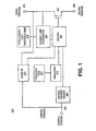
Figure 1 is a block diagram illustrating one embodiment of a power supply regulator in accordance with the teachings of the present invention; -
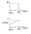
Figure 2 is a diagram illustrating the relationship between the duty cycle and the current (IC) into the control terminal of one embodiment of a power supply regulator in accordance with the teachings of the present invention ; -
Figure 3 is a diagram illustrating the relationship between the peak current limit threshold Ip and the current (IC) into the control terminal of another embodiment of a power supply regulator in accordance with the teachings of the present invention; -
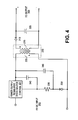
Figure 4 is a schematic diagram illustrating one embodiment of a power supply that has a relatively constant voltage and current characteristic in accordance with the teachings of the present invention ; -
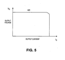
Figure 5 a diagram illustrating the relationship between the output current and output voltage of one embodiment of a power supply in accordance with the teachings of the present invention; -
Figure 6 is a schematic diagram illustrating another embodiment of a power supply that has a relatively constant voltage and current characteristic in accordance with the teachings of the present invention; and -
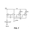
Figure 7 is a schematic of one embodiment of a trim circuit block used for frequency trim or peak current limit threshold trim in accordance with the teachings of the present invention. - Embodiments of methods and apparatuses for trimming a power supply for increased accuracy in the maximum deliverable power of the power supply are disclosed. In the following description, numerous specific details are set forth in order to provide a thorough understanding of the present invention. It will be apparent, however, to one having ordinary skill in the art that the specific detail need not be employed to practice the present invention. In other instances, well-known materials or methods have not been described in detail in order to avoid obscuring the present invention.
- Reference throughout this specification to "one embodiment" or "an embodiment" means that a particular feature, structure or characteristic described in connection with the embodiment is included in at least one embodiment of the present invention. Thus, the appearances of the phrases "in one embodiment" or "in an embodiment" in various places throughout this specification are not necessarily all referring to the same embodiment. Furthermore, the particular features, structures or characteristics may be combined in any suitable manner in one or more embodiments.
- In various embodiments, low cost integrated solutions are provided for controlling the maximum deliverable power by trimming of the internally set peak current limit threshold Ip, and operating frequency f of a power supply regulator in such a way that the product of the oscillating frequency f and the square of the peak current limit threshold Ip is a constant or substantially uniform from one regulator to the next. Rather than defining an independent operating frequency f, and an independent peak current limit threshold Ip, the two are made dependent on each other, and will together determine the maximum deliverable power in an AC to DC or DC to DC power supply.
- In one embodiment, the maximum deliverable power in a switch mode power supply that is designed to work in discontinuous operation is determined by the primary inductance of the transformer, operating frequency f, and peak current limit threshold Ip. In one embodiment, to keep the maximum deliverable power substantially constant, the operating frequency f and the peak current limit threshold Ip are trimmed in a way such that the product of Equation 1 below:

- To illustrate,
Figure 1 is a block diagram illustrating one embodiment of apower supply regulator 321 in accordance with the teachings of the present invention. In one embodiment, thepower supply regulator 321 is included on a single monolithic chip having as few as three electrical terminals. Thepower supply regulator 321 includes apower switch 365 coupled betweendrain terminal 323 andsource terminal 329. In one embodiment,power switch 365 includes a metal oxide semiconductor field effect transistor (MOSFET). - As shown in the embodiment depicted in
Figure 1 , thepower supply regulator 321 also includes a controlcurrent sensor 369 coupled to sense the excess control current through thecontrol terminal 325. The excess control current is the total control terminal current less the supply current of the regulator. The supply current of the regulator is known. Therefore, the total Control terminal current can be deduced from the excess control current. The current received through thecontrol terminal 325 is responsive to a reflected voltage from an energy transfer element of a power supply inFigure 4 that thepower supply regulator 321 is coupled to regulate. - In one embodiment, the
power switch 365 is switched in response to the current received through thecontrol terminal 325. Acontrol circuit 367 is coupled to controlcurrent sensor 369 andpower switch 365. In one embodiment, thecontrol circuit 367 modulates the duty cycle and the peak current limit threshold Ip of thepower switch 365 to regulate the output of the power supply inFigure 4 . Accordingly, power switch is switched on and off bycontrol circuitry 367 to enable and disable the delivery of power to the output of the power supply to regulate the power supply output. In so doing, thecontrol circuit 367 modulates the duty cycle of thepower switch 365 when the Control terminal current exceeds a control threshold current. In one embodiment, thecontrol circuit 367 reduces the duty cycle when the Control terminal current exeeds the control threshold current. In one embodiment, thecontrol circuit 367 reduces the peak current limit threshold Ip when the Control terminal current is below the same control threshold current. - In one embodiment, the
current limit comparator 368 compares the current of theswitch 365 to a threshold. When the current of theswitch 365 exceeds the threshold of the comparator, the switch is turned off immediately for the remainder of the switching cycle. In one embodiment, the peak current limit thresholdtrim block 370 sets the peak current limit threshold Ip of the current limit comparator at the control threshold current. The peak current limit threshold Ip is reduced when the Control terminal current goes below the control threshold current. In one embodiment, thepower supply regulator 321 also includes a start-upcircuit 371 coupled to control terminal 325,drain terminal 323 andcontrol circuit 367. Thepower supply regulator 321 also includes anoscillator circuit 373, and afrequency trim circuit 372 to program the operating frequency in theoscillator circuit 373. In one embodiment,oscillator 373 is coupled to provide an oscillating signal having the operating frequency f, which is received bycontrol circuit 367 to switchpower switch 365. In one embodiment,power switch 365 is switched in response to the oscillating signal received fromoscillator 373. -
Figure 2 shows a diagram illustrating the relationship between the duty cycle and the current (IC) into the control terminal of one embodiment ofpower supply regulator 321. The diagram shows two different regions of operation. In the first region, the current (IC) into the control terminal is lower than the Control threshold current and the duty cycle is maximum, and thepower supply regulator 321 operates in current limit mode. In this mode, the peak current limit threshold Ip is reduced to regulate the current at the output of the power supply. In the second region with increased current (IC) into the control terminal output voltage is controlled by regulating the duty cycle. -
Figure 3 shows a diagram illustrating the relationship between the peak current limit threshold Ip and the current (IC) into the control terminal of one embodiment ofpower supply regulator 321. The peak current limit threshold Ip increases with increased current (IC) into the control terminal of thepower supply regulator 321. -
Figure 4 shows one embodiment of a flyback power supply that has a relatively constant voltage and current characteristic. The feedback information is provided to thepower supply regulator 321 at its control terminal. The current at the control terminal is proportional to the voltage acrossresistor 235, which in turn is responsive to theoutput voltage 200. Thepower supply regulator 321 reduces the duty cycle of the integrated power metal oxide semiconductor field effect transistor (MOSFET) included inpower supply regulator 321 when the voltage acrossresistor 235 increases above the voltage necessary to establish a Control threshold current. In this section, the output is in constant voltage mode. Thepower supply regulator 321 reduces the peak current limit threshold Ip of the integrated power MOSFET when the voltage acrossresistor 235 decreases below the voltage necessary to establish the Control threshold current. The peak current limit threshold Ip is reduced as a function of the voltage acrossresistor 235 to regulate the output load current. -
Figure 5 is a diagram illustrating the relationship between the output current and output voltage of one embodiment of a power supply in accordance with the teachings of the present invention. As can be seen incurve 400, the power supply exhibits a substantially constant output current and voltage characteristic. That is, as output current increases, the output voltage remains substantially constant until the output current reaches an output current threshold. As the output current approaches the output current threshold, the output voltage decreases as the output current remains substantially constant over the drop in output voltage. It is appreciated that the constant output voltage and constant output current characteristics of the present invention are suitable for battery charger applications or the like. -
Figure 6 shows one embodiment of a buckconverter power supply 601 that has a relatively constant voltage and current characteristic. The feedback information is provided to thepower supply regulator 321 at its control terminal. The current at the control terminal is proportional to the voltage acrossresistor 603, which in turn is responsive to theDC output 600 voltage. Thepower supply regulator 321 reduces the duty cycle of the integrated power metal oxide semiconductor field effect transistor (MOSFET) included inpower supply regulator 321 when the voltage acrossresistor 603 increases above the voltage necessary to establish the Control threshold current. In this section, the output is in constant voltage mode. Thepower supply regulator 321 reduces the peak current limit threshold Ip of the integrated power MOSFET when the voltage acrossresistor 603 decreases below the voltage necessary to establish the Control threshold current. The peak current limit threshold Ip is reduced as a function of the voltage acrossresistor 603 to regulate the output load current. -
Figure 7 is a schematic of one embodiment of a trim circuit block used for frequency trim or peak current limit threshold Ip trim in accordance with the teachings of the present invention. In this circuit, Iref is a reference current source, and Itrim is the trimmed current source. Itrim is a current mirror of Iref. The ratio of the current mirror changes as more zeners are trimmed. For example whenzener 750 is not trimmed,transistor 730 will be practically open since the voltage drop of the zener will inhibit any conduction through the transistor. Whenzener 750 is trimmed (shorted),transistor 730 will conduct and be in parallel totransistor 720, thereby changing the ratio of the current mirror. - For the oscillator frequency block, Itrim can be used to charge and discharge a capacitor. For the current limit comparator, Itrim can be used to set the threshold of the comparator. In one embodiment, the peak current limit threshold Ip can be trimmed first. Then the target frequency or operating frequency f can be adjusted by the measured current limit so that the product of the peak current limit threshold Ip squared and operating frequency f will remain constant. This method will provide a constant deliverable power to the output load of the power supply.
- In yet another embodiment, the operating frequency f can be adjusted based on the peak current limit threshold Ip and control threshold current so that the product of Ip m.fn divided by the control threshold current is constant. Since the control threshold current tracks the output voltage of the power supply, this method essentially compensates the deliverable power for the output voltage, resulting in constant power supply output current at the maximum output power point on the power supply output characteristic.
Claims (10)
- A power supply regulator (321), comprising:a power switch (365) coupled between first and second terminals (323, 329);a control circuit (367) coupled to switch the power switch (365);a current limit circuit coupled to the power switch (365) and the control circuit (367) to control a current through the power switch (365) during operation of the power supply regulator (321), the current limit circuit having a peak current limit threshold Ip, andan oscillator (373) coupled to provide the control circuit (367) an oscillating signal, the control circuit (367) to switch the power switch (365) in response to the oscillating signal, the oscillating signal having an operating frequency f, wherein the maximum deliverable power is controlled by trimming during manufacture of said power supply regulator the internally set peak current limit threshold Ip and the operating frequency f to maintain a product of Ip m, fn constant, where m and n are constants.
- The power supply regulator of claim 1, wherein where m is substantially equal to 2 and n is substantially equal to 1.
- The power supply regulator of claim 1 or 2,wherein the product of 1p m·fn of the power supply regulator (321) is substantially constant with a product of 1p m·fn of another power supply regulator.
- The power supply regulator of any preceding claim, wherein the power supply regulator (321) is part of a flyback converter power supply.
- The power supply regulator of claims 1, 2 or 3 wherein the power supply regulator (321) is part of a buck converter power supply (601).
- The power supply regulator of any preceding claim, wherein the operating frequency (f) is substantially constant during operation under all operating conditions of the power supply regulator (321).
- The power supply regulator of any one of claims 1 to 5, wherein the operating frequency (f) is substantially constant during operation under a fixed range of operating conditions of the power supply regulator (321).
- The power supply regulator of any one preceding claim, further comprising a peak current limit threshold trim circuit.
- The power supply regulator of any one preceding claim, further comprising a frequency trim circuit.
- A switched mode power supply, comprising an energy transfer element having an output coupled to an output of the switched mode power supply; and a power supply regulator (321) according to anyone preceding claim.
Applications Claiming Priority (4)
| Application Number | Priority Date | Filing Date | Title |
|---|---|---|---|
| US316583 | 1981-10-30 | ||
| US31658301P | 2001-08-31 | 2001-08-31 | |
| US10/218,763 US6747443B2 (en) | 2001-08-31 | 2002-08-14 | Method and apparatus for trimming current limit and frequency to maintain a constant maximum power |
| US218763 | 2002-08-14 |
Publications (3)
| Publication Number | Publication Date |
|---|---|
| EP1289107A2 EP1289107A2 (en) | 2003-03-05 |
| EP1289107A3 EP1289107A3 (en) | 2003-05-21 |
| EP1289107B1 true EP1289107B1 (en) | 2008-08-13 |
Family
ID=26913228
Family Applications (1)
| Application Number | Title | Priority Date | Filing Date |
|---|---|---|---|
| EP02256000A Expired - Fee Related EP1289107B1 (en) | 2001-08-31 | 2002-08-29 | Method and apparatus for trimming current limit and frequency to maintain a constant maximum power |
Country Status (4)
| Country | Link |
|---|---|
| US (6) | US6747443B2 (en) |
| EP (1) | EP1289107B1 (en) |
| JP (2) | JP4361250B2 (en) |
| DE (1) | DE60228176D1 (en) |
Families Citing this family (59)
| Publication number | Priority date | Publication date | Assignee | Title |
|---|---|---|---|---|
| US6747443B2 (en) * | 2001-08-31 | 2004-06-08 | Power Integrations, Inc. | Method and apparatus for trimming current limit and frequency to maintain a constant maximum power |
| US6781357B2 (en) * | 2001-09-27 | 2004-08-24 | Power Integrations, Inc. | Method and apparatus for maintaining a constant load current with line voltage in a switch mode power supply |
| US6897662B2 (en) * | 2001-10-26 | 2005-05-24 | Micrel, Incorporated | Method and apparatus for optimizing the accuracy of an electronic circuit |
| KR100554080B1 (en) * | 2002-09-19 | 2006-02-22 | 엘지전자 주식회사 | Voltage regulation circuit for a m0nitor |
| US7656096B2 (en) * | 2003-04-30 | 2010-02-02 | International Rectifier Corporation | Hybrid ballast control circuit in a simplified package |
| US7254044B2 (en) * | 2005-01-11 | 2007-08-07 | Artesyn Technologies, Inc. | Current limit circuit and power supply including same |
| US7272025B2 (en) * | 2005-01-18 | 2007-09-18 | Power Integrations, Inc. | Method and apparatus to control either a regulated or an unregulated output of a switching power supply |
| US7453709B2 (en) | 2005-07-08 | 2008-11-18 | Power Integrations, Inc. | Method and apparatus for increasing the power capability of a power supply |
| US7215107B2 (en) | 2005-07-11 | 2007-05-08 | Power Integrations, Inc. | Method and apparatus to limit output power in a switching power supply |
| US7567066B2 (en) | 2006-10-04 | 2009-07-28 | Power Integrations, Inc. | Integrated switch with internally adjusted conduction time |
| US7518885B2 (en) * | 2006-10-04 | 2009-04-14 | Power Integrations, Inc. | Method and apparatus for a control circuit with multiple operation modes |
| US7502236B2 (en) * | 2006-10-04 | 2009-03-10 | Power Integrations, Inc. | Power supply controller responsive to a feedforward signal |
| US7576528B2 (en) | 2006-10-04 | 2009-08-18 | Power Integrations, Inc. | Control circuit responsive to an impedance |
| US7733073B2 (en) * | 2007-09-28 | 2010-06-08 | Infineon Technologies Ag | Current regulator with current threshold dependent duty cycle |
| US8576589B2 (en) | 2008-01-30 | 2013-11-05 | Cirrus Logic, Inc. | Switch state controller with a sense current generated operating voltage |
| US9305609B2 (en) * | 2008-04-30 | 2016-04-05 | Micron Technology, Inc. | System and method of command based and current limit controlled memory device power up |
| US7952895B2 (en) | 2008-05-29 | 2011-05-31 | Power Integrations, Inc. | Method and apparatus for implementing an unregulated dormant mode in a power converter |
| US7770039B2 (en) | 2008-05-29 | 2010-08-03 | iGo, Inc | Primary side control circuit and method for ultra-low idle power operation |
| US7779278B2 (en) | 2008-05-29 | 2010-08-17 | Igo, Inc. | Primary side control circuit and method for ultra-low idle power operation |
| US7995359B2 (en) | 2009-02-05 | 2011-08-09 | Power Integrations, Inc. | Method and apparatus for implementing an unregulated dormant mode with an event counter in a power converter |
| US8385088B2 (en) | 2010-12-06 | 2013-02-26 | Power Integrations, Inc. | Method and apparatus for implementing an unregulated dormant mode with output reset in a power converter |
| US7795759B2 (en) | 2008-06-27 | 2010-09-14 | iGo, Inc | Load condition controlled power strip |
| US7795760B2 (en) | 2008-07-25 | 2010-09-14 | Igo, Inc. | Load condition controlled power module |
| US7800252B2 (en) | 2008-06-27 | 2010-09-21 | Igo, Inc. | Load condition controlled wall plate outlet system |
| CN102106068B (en) * | 2008-07-23 | 2014-08-27 | 半导体元件工业有限责任公司 | Method of forming a switching regulator and structure therefor |
| TWI384342B (en) * | 2008-08-01 | 2013-02-01 | Leadtrend Tech Corp | Current control method and apparatus |
| US8159204B2 (en) | 2008-09-29 | 2012-04-17 | Active-Semi, Inc. | Regulating current output from a buck converter without external current sensing |
| US8284572B2 (en) * | 2008-11-20 | 2012-10-09 | Leadtrend Technology Corp. | Current control method and apparatus |
| JP2011062026A (en) * | 2009-09-11 | 2011-03-24 | Panasonic Corp | Switching power supply device and semiconductor device |
| US9178415B1 (en) | 2009-10-15 | 2015-11-03 | Cirrus Logic, Inc. | Inductor over-current protection using a volt-second value representing an input voltage to a switching power converter |
| US8487591B1 (en) | 2009-12-31 | 2013-07-16 | Cirrus Logic, Inc. | Power control system with power drop out immunity and uncompromised startup time |
| US8310850B2 (en) * | 2009-12-22 | 2012-11-13 | Power Integrations, Inc. | Method and apparatus for varying current limit to limit an output power of a power supply |
| US8729811B2 (en) | 2010-07-30 | 2014-05-20 | Cirrus Logic, Inc. | Dimming multiple lighting devices by alternating energy transfer from a magnetic storage element |
| US8912781B2 (en) | 2010-07-30 | 2014-12-16 | Cirrus Logic, Inc. | Integrated circuit switching power supply controller with selectable buck mode operation |
| US9510401B1 (en) | 2010-08-24 | 2016-11-29 | Cirrus Logic, Inc. | Reduced standby power in an electronic power control system |
| US9025347B2 (en) | 2010-12-16 | 2015-05-05 | Cirrus Logic, Inc. | Switching parameter based discontinuous mode-critical conduction mode transition |
| EP2512021B1 (en) | 2011-04-14 | 2017-07-19 | Nxp B.V. | A controller for a switched mode power converter |
| WO2012167161A1 (en) | 2011-06-03 | 2012-12-06 | Cirrus Logic, Inc. | Primary-side control of a switching power converter with feed forward delay compensation |
| CN103636109B (en) | 2011-06-03 | 2016-08-17 | 塞瑞斯逻辑公司 | For operating method and apparatus and the electric power distribution system of switched power transducer |
| JP5762205B2 (en) * | 2011-08-04 | 2015-08-12 | ラピスセミコンダクタ株式会社 | Semiconductor integrated circuit |
| WO2013090777A2 (en) | 2011-12-14 | 2013-06-20 | Cirrus Logic, Inc. | Isolation of secondary transformer winding current during auxiliary power supply generation |
| US9520794B2 (en) | 2012-07-25 | 2016-12-13 | Philips Lighting Holding B.V | Acceleration of output energy provision for a load during start-up of a switching power converter |
| US9024541B2 (en) | 2013-03-07 | 2015-05-05 | Cirrus Logic, Inc. | Utilizing secondary-side conduction time parameters of a switching power converter to provide energy to a load |
| CN105265017B (en) | 2013-03-11 | 2017-09-08 | 飞利浦照明控股有限公司 | The reduction changed using the supply current of compensating current control |
| EP2973969B1 (en) | 2013-03-11 | 2021-05-12 | Signify Holding B.V. | Quantization error reduction in constant output current control drivers |
| WO2014186765A1 (en) | 2013-05-17 | 2014-11-20 | Cirrus Logic, Inc. | Single pin control of bipolar junction transistor (bjt)-based power stage |
| WO2014186776A1 (en) | 2013-05-17 | 2014-11-20 | Cirrus Logic, Inc. | Charge pump-based circuitry for bjt power supply |
| JP5838997B2 (en) * | 2013-05-21 | 2016-01-06 | トヨタ自動車株式会社 | Power conversion apparatus and power correction method |
| CN103280960B (en) * | 2013-05-31 | 2015-04-15 | 华为技术有限公司 | Current-limiting device and current-limiting method |
| WO2015017317A2 (en) | 2013-07-29 | 2015-02-05 | Cirrus Logic, Inc. | Two terminal drive of bipolar junction transistor (bjt) for switch-mode operation of a light emitting diode (led)-based bulb |
| WO2015017315A1 (en) | 2013-07-29 | 2015-02-05 | Cirrus Logic, Inc. | Compensating for a reverse recovery time period of a bipolar junction transistor (bjt) in switch-mode operation of a light-emitting diode (led)-based bulb |
| US9161401B1 (en) | 2014-03-20 | 2015-10-13 | Cirrus Logic, Inc. | LED (light-emitting diode) string derived controller power supply |
| US9214862B2 (en) | 2014-04-17 | 2015-12-15 | Philips International, B.V. | Systems and methods for valley switching in a switching power converter |
| US9325236B1 (en) | 2014-11-12 | 2016-04-26 | Koninklijke Philips N.V. | Controlling power factor in a switching power converter operating in discontinuous conduction mode |
| JP6485047B2 (en) * | 2015-01-08 | 2019-03-20 | 富士電機株式会社 | Switching power supply |
| US9504118B2 (en) | 2015-02-17 | 2016-11-22 | Cirrus Logic, Inc. | Resistance measurement of a resistor in a bipolar junction transistor (BJT)-based power stage |
| US9609701B2 (en) | 2015-02-27 | 2017-03-28 | Cirrus Logic, Inc. | Switch-mode drive sensing of reverse recovery in bipolar junction transistor (BJT)-based power converters |
| US9603206B2 (en) | 2015-02-27 | 2017-03-21 | Cirrus Logic, Inc. | Detection and control mechanism for tail current in a bipolar junction transistor (BJT)-based power stage |
| US10069399B1 (en) | 2017-04-11 | 2018-09-04 | Infineon Technologies Austria Ag | Selecting an aspect ratio for current monitoring |
Family Cites Families (18)
| Publication number | Priority date | Publication date | Assignee | Title |
|---|---|---|---|---|
| US4823070A (en) * | 1986-11-18 | 1989-04-18 | Linear Technology Corporation | Switching voltage regulator circuit |
| KR910008548B1 (en) * | 1987-05-07 | 1991-10-18 | 가부시키가이샤 히타치세이사쿠쇼 | Voltage controller for charging generator |
| US5390101A (en) | 1994-01-04 | 1995-02-14 | Motorola, Inc. | Flyback power supply having a VCO controlled switching rate |
| US5528483A (en) | 1994-08-23 | 1996-06-18 | Siliconix, Inc. | Voltage converter with frequency shift protection against overload current |
| GB2298532A (en) * | 1995-02-28 | 1996-09-04 | Ibm | Switch mode power supply |
| US5747976A (en) * | 1996-03-26 | 1998-05-05 | Raytheon Company | Constant on-time architecture for switching regulators |
| EP0871328B1 (en) * | 1997-04-09 | 2003-08-13 | STMicroelectronics S.r.l. | Control of the output power of a dc-dc converter upon varying the switching frequency |
| US6232775B1 (en) * | 1997-12-26 | 2001-05-15 | Alps Electric Co., Ltd | Magneto-impedance element, and azimuth sensor, autocanceler and magnetic head using the same |
| US6226190B1 (en) | 1998-02-27 | 2001-05-01 | Power Integrations, Inc. | Off-line converter with digital control |
| US6147883A (en) | 1998-11-16 | 2000-11-14 | Power Integrations, Inc. | Output feedback and under-voltage detection |
| JP2001095233A (en) | 1999-09-22 | 2001-04-06 | Tdk Corp | Switching power supply |
| US6154377A (en) | 1999-10-08 | 2000-11-28 | Power Integrations, Inc. | Method and apparatus reducing overshoot in a power supply controller |
| JP4399929B2 (en) * | 1999-12-02 | 2010-01-20 | パナソニック株式会社 | Switching power supply |
| US6232755B1 (en) * | 2000-01-31 | 2001-05-15 | Intel Corporation | Switching voltage regulator that adjusts a timing in response to a load transient |
| JP2002056678A (en) * | 2000-08-14 | 2002-02-22 | Mitsubishi Electric Corp | Substrate bias voltage generating circuit |
| US6424229B1 (en) * | 2001-06-04 | 2002-07-23 | Ericsson Inc. | Tunable voltage controlled oscillator circuit having aided acquisition and methods for operating the same |
| US6747443B2 (en) * | 2001-08-31 | 2004-06-08 | Power Integrations, Inc. | Method and apparatus for trimming current limit and frequency to maintain a constant maximum power |
| WO2003085476A1 (en) * | 2002-04-03 | 2003-10-16 | International Rectifier Corporation | Synchronous buck converter improvements |
-
2002
- 2002-08-14 US US10/218,763 patent/US6747443B2/en not_active Expired - Lifetime
- 2002-08-29 EP EP02256000A patent/EP1289107B1/en not_active Expired - Fee Related
- 2002-08-29 DE DE60228176T patent/DE60228176D1/en not_active Expired - Lifetime
- 2002-08-30 JP JP2002252748A patent/JP4361250B2/en not_active Expired - Fee Related
-
2004
- 2004-04-08 US US10/820,667 patent/US6882134B2/en not_active Expired - Fee Related
-
2005
- 2005-03-02 US US11/071,380 patent/US6992471B2/en not_active Expired - Fee Related
- 2005-09-28 US US11/237,254 patent/US7109696B2/en not_active Expired - Fee Related
-
2006
- 2006-08-11 US US11/503,448 patent/US7345462B2/en not_active Expired - Fee Related
-
2008
- 2008-01-25 US US12/020,435 patent/US7486062B2/en not_active Expired - Fee Related
-
2009
- 2009-05-22 JP JP2009124279A patent/JP5269695B2/en not_active Expired - Fee Related
Also Published As
| Publication number | Publication date |
|---|---|
| EP1289107A3 (en) | 2003-05-21 |
| US20040189274A1 (en) | 2004-09-30 |
| US7345462B2 (en) | 2008-03-18 |
| US20080136392A1 (en) | 2008-06-12 |
| US6992471B2 (en) | 2006-01-31 |
| US20030043601A1 (en) | 2003-03-06 |
| DE60228176D1 (en) | 2008-09-25 |
| US20050146900A1 (en) | 2005-07-07 |
| US6882134B2 (en) | 2005-04-19 |
| US20060022659A1 (en) | 2006-02-02 |
| US6747443B2 (en) | 2004-06-08 |
| JP2009183145A (en) | 2009-08-13 |
| US7109696B2 (en) | 2006-09-19 |
| EP1289107A2 (en) | 2003-03-05 |
| US20060273773A1 (en) | 2006-12-07 |
| JP5269695B2 (en) | 2013-08-21 |
| JP4361250B2 (en) | 2009-11-11 |
| JP2003134811A (en) | 2003-05-09 |
| US7486062B2 (en) | 2009-02-03 |
Similar Documents
| Publication | Publication Date | Title |
|---|---|---|
| EP1289107B1 (en) | Method and apparatus for trimming current limit and frequency to maintain a constant maximum power | |
| EP2270965B1 (en) | Method and apparatus for maintaining a constant load current with line voltage in a switch mode power supply | |
| US7729137B2 (en) | Switching power supply and regulation circuit | |
| US7554826B2 (en) | Method and apparatus to control output power from a switching power supply | |
| US7944190B2 (en) | Control circuit of power supply unit which controls output power of external power supply based upon current from the external power supply, power supply unit and control method thereof | |
| EP1744439A2 (en) | Method and apparatus for fault detection in a switching power supply | |
| CN108631590B (en) | Voltage converter, controller and control method thereof | |
| US4584517A (en) | Self-oscillating DC-DC switching voltage regulator | |
| US20070057657A1 (en) | Constant voltage control device | |
| US7619394B2 (en) | Capacitor charger with a modulated current varying with an input voltage and method thereof | |
| KR20000074234A (en) | an electronic ballast system | |
| US7170763B2 (en) | Apparatus and method for constant delta current control in a capacitor charger | |
| JPH08317643A (en) | Switching power-supply apparatus |
Legal Events
| Date | Code | Title | Description |
|---|---|---|---|
| PUAI | Public reference made under article 153(3) epc to a published international application that has entered the european phase |
Free format text: ORIGINAL CODE: 0009012 |
|
| AK | Designated contracting states |
Kind code of ref document: A2 Designated state(s): AT BE BG CH CY CZ DE DK EE ES FI FR GB GR IE IT LI LU MC NL PT SE SK TR |
|
| AX | Request for extension of the european patent |
Extension state: AL LT LV MK RO SI |
|
| PUAL | Search report despatched |
Free format text: ORIGINAL CODE: 0009013 |
|
| RIC1 | Information provided on ipc code assigned before grant |
Ipc: 7H 02M 3/22 A Ipc: 7H 02M 7/217 B Ipc: 7H 02M 1/00 B Ipc: 7H 02M 3/335 B Ipc: 7H 02M 3/337 B Ipc: 7H 02M 3/156 B |
|
| AK | Designated contracting states |
Designated state(s): AT BE BG CH CY CZ DE DK EE ES FI FR GB GR IE IT LI LU MC NL PT SE SK TR |
|
| AX | Request for extension of the european patent |
Extension state: AL LT LV MK RO SI |
|
| 17P | Request for examination filed |
Effective date: 20030818 |
|
| 17Q | First examination report despatched |
Effective date: 20031121 |
|
| AKX | Designation fees paid |
Designated state(s): DE FR GB IT NL SE |
|
| GRAP | Despatch of communication of intention to grant a patent |
Free format text: ORIGINAL CODE: EPIDOSNIGR1 |
|
| GRAS | Grant fee paid |
Free format text: ORIGINAL CODE: EPIDOSNIGR3 |
|
| RAP3 | Party data changed (applicant data changed or rights of an application transferred) |
Owner name: POWER INTEGRATIONS, INC. |
|
| GRAA | (expected) grant |
Free format text: ORIGINAL CODE: 0009210 |
|
| AK | Designated contracting states |
Kind code of ref document: B1 Designated state(s): DE FR GB IT NL SE |
|
| REG | Reference to a national code |
Ref country code: GB Ref legal event code: FG4D |
|
| REF | Corresponds to: |
Ref document number: 60228176 Country of ref document: DE Date of ref document: 20080925 Kind code of ref document: P |
|
| REG | Reference to a national code |
Ref country code: SE Ref legal event code: TRGR |
|
| PLBE | No opposition filed within time limit |
Free format text: ORIGINAL CODE: 0009261 |
|
| STAA | Information on the status of an ep patent application or granted ep patent |
Free format text: STATUS: NO OPPOSITION FILED WITHIN TIME LIMIT |
|
| 26N | No opposition filed |
Effective date: 20090514 |
|
| PGFP | Annual fee paid to national office [announced via postgrant information from national office to epo] |
Ref country code: SE Payment date: 20130828 Year of fee payment: 12 |
|
| PGFP | Annual fee paid to national office [announced via postgrant information from national office to epo] |
Ref country code: NL Payment date: 20140826 Year of fee payment: 13 |
|
| PGFP | Annual fee paid to national office [announced via postgrant information from national office to epo] |
Ref country code: GB Payment date: 20140827 Year of fee payment: 13 Ref country code: FR Payment date: 20140818 Year of fee payment: 13 |
|
| PGFP | Annual fee paid to national office [announced via postgrant information from national office to epo] |
Ref country code: IT Payment date: 20140823 Year of fee payment: 13 |
|
| REG | Reference to a national code |
Ref country code: SE Ref legal event code: EUG |
|
| PG25 | Lapsed in a contracting state [announced via postgrant information from national office to epo] |
Ref country code: SE Free format text: LAPSE BECAUSE OF NON-PAYMENT OF DUE FEES Effective date: 20140830 |
|
| GBPC | Gb: european patent ceased through non-payment of renewal fee |
Effective date: 20150829 |
|
| PG25 | Lapsed in a contracting state [announced via postgrant information from national office to epo] |
Ref country code: IT Free format text: LAPSE BECAUSE OF NON-PAYMENT OF DUE FEES Effective date: 20150829 |
|
| REG | Reference to a national code |
Ref country code: NL Ref legal event code: MM Effective date: 20150901 |
|
| REG | Reference to a national code |
Ref country code: FR Ref legal event code: ST Effective date: 20160429 |
|
| PG25 | Lapsed in a contracting state [announced via postgrant information from national office to epo] |
Ref country code: NL Free format text: LAPSE BECAUSE OF NON-PAYMENT OF DUE FEES Effective date: 20150901 |
|
| PG25 | Lapsed in a contracting state [announced via postgrant information from national office to epo] |
Ref country code: GB Free format text: LAPSE BECAUSE OF NON-PAYMENT OF DUE FEES Effective date: 20150829 |
|
| PG25 | Lapsed in a contracting state [announced via postgrant information from national office to epo] |
Ref country code: FR Free format text: LAPSE BECAUSE OF NON-PAYMENT OF DUE FEES Effective date: 20150831 |
|
| PGFP | Annual fee paid to national office [announced via postgrant information from national office to epo] |
Ref country code: DE Payment date: 20180829 Year of fee payment: 17 |
|
| REG | Reference to a national code |
Ref country code: DE Ref legal event code: R119 Ref document number: 60228176 Country of ref document: DE |
|
| PG25 | Lapsed in a contracting state [announced via postgrant information from national office to epo] |
Ref country code: DE Free format text: LAPSE BECAUSE OF NON-PAYMENT OF DUE FEES Effective date: 20200303 |