EP1289660B1 - High-performance system for parallel and selective dispensing of micro-droplets - Google Patents
High-performance system for parallel and selective dispensing of micro-droplets Download PDFInfo
- Publication number
- EP1289660B1 EP1289660B1 EP01945453A EP01945453A EP1289660B1 EP 1289660 B1 EP1289660 B1 EP 1289660B1 EP 01945453 A EP01945453 A EP 01945453A EP 01945453 A EP01945453 A EP 01945453A EP 1289660 B1 EP1289660 B1 EP 1289660B1
- Authority
- EP
- European Patent Office
- Prior art keywords
- membrane
- wells
- substrate
- dispenser system
- cells
- Prior art date
- Legal status (The legal status is an assumption and is not a legal conclusion. Google has not performed a legal analysis and makes no representation as to the accuracy of the status listed.)
- Expired - Lifetime
Links
Images


Classifications
-
- B—PERFORMING OPERATIONS; TRANSPORTING
- B01—PHYSICAL OR CHEMICAL PROCESSES OR APPARATUS IN GENERAL
- B01L—CHEMICAL OR PHYSICAL LABORATORY APPARATUS FOR GENERAL USE
- B01L3/00—Containers or dishes for laboratory use, e.g. laboratory glassware; Droppers
- B01L3/02—Burettes; Pipettes
-
- B—PERFORMING OPERATIONS; TRANSPORTING
- B01—PHYSICAL OR CHEMICAL PROCESSES OR APPARATUS IN GENERAL
- B01L—CHEMICAL OR PHYSICAL LABORATORY APPARATUS FOR GENERAL USE
- B01L3/00—Containers or dishes for laboratory use, e.g. laboratory glassware; Droppers
- B01L3/02—Burettes; Pipettes
- B01L3/0241—Drop counters; Drop formers
- B01L3/0268—Drop counters; Drop formers using pulse dispensing or spraying, eg. inkjet type, piezo actuated ejection of droplets from capillaries
-
- B—PERFORMING OPERATIONS; TRANSPORTING
- B01—PHYSICAL OR CHEMICAL PROCESSES OR APPARATUS IN GENERAL
- B01J—CHEMICAL OR PHYSICAL PROCESSES, e.g. CATALYSIS OR COLLOID CHEMISTRY; THEIR RELEVANT APPARATUS
- B01J19/00—Chemical, physical or physico-chemical processes in general; Their relevant apparatus
- B01J19/0046—Sequential or parallel reactions, e.g. for the synthesis of polypeptides or polynucleotides; Apparatus and devices for combinatorial chemistry or for making molecular arrays
-
- B—PERFORMING OPERATIONS; TRANSPORTING
- B01—PHYSICAL OR CHEMICAL PROCESSES OR APPARATUS IN GENERAL
- B01J—CHEMICAL OR PHYSICAL PROCESSES, e.g. CATALYSIS OR COLLOID CHEMISTRY; THEIR RELEVANT APPARATUS
- B01J2219/00—Chemical, physical or physico-chemical processes in general; Their relevant apparatus
- B01J2219/00274—Sequential or parallel reactions; Apparatus and devices for combinatorial chemistry or for making arrays; Chemical library technology
- B01J2219/00277—Apparatus
- B01J2219/00279—Features relating to reactor vessels
- B01J2219/00306—Reactor vessels in a multiple arrangement
- B01J2219/00313—Reactor vessels in a multiple arrangement the reactor vessels being formed by arrays of wells in blocks
- B01J2219/00315—Microtiter plates
- B01J2219/00317—Microwell devices, i.e. having large numbers of wells
-
- B—PERFORMING OPERATIONS; TRANSPORTING
- B01—PHYSICAL OR CHEMICAL PROCESSES OR APPARATUS IN GENERAL
- B01J—CHEMICAL OR PHYSICAL PROCESSES, e.g. CATALYSIS OR COLLOID CHEMISTRY; THEIR RELEVANT APPARATUS
- B01J2219/00—Chemical, physical or physico-chemical processes in general; Their relevant apparatus
- B01J2219/00274—Sequential or parallel reactions; Apparatus and devices for combinatorial chemistry or for making arrays; Chemical library technology
- B01J2219/00277—Apparatus
- B01J2219/00351—Means for dispensing and evacuation of reagents
- B01J2219/00364—Pipettes
- B01J2219/00371—Pipettes comprising electrodes
-
- B—PERFORMING OPERATIONS; TRANSPORTING
- B01—PHYSICAL OR CHEMICAL PROCESSES OR APPARATUS IN GENERAL
- B01J—CHEMICAL OR PHYSICAL PROCESSES, e.g. CATALYSIS OR COLLOID CHEMISTRY; THEIR RELEVANT APPARATUS
- B01J2219/00—Chemical, physical or physico-chemical processes in general; Their relevant apparatus
- B01J2219/00274—Sequential or parallel reactions; Apparatus and devices for combinatorial chemistry or for making arrays; Chemical library technology
- B01J2219/00277—Apparatus
- B01J2219/00351—Means for dispensing and evacuation of reagents
- B01J2219/00378—Piezo-electric or ink jet dispensers
-
- B—PERFORMING OPERATIONS; TRANSPORTING
- B01—PHYSICAL OR CHEMICAL PROCESSES OR APPARATUS IN GENERAL
- B01J—CHEMICAL OR PHYSICAL PROCESSES, e.g. CATALYSIS OR COLLOID CHEMISTRY; THEIR RELEVANT APPARATUS
- B01J2219/00—Chemical, physical or physico-chemical processes in general; Their relevant apparatus
- B01J2219/00274—Sequential or parallel reactions; Apparatus and devices for combinatorial chemistry or for making arrays; Chemical library technology
- B01J2219/00277—Apparatus
- B01J2219/00497—Features relating to the solid phase supports
- B01J2219/00527—Sheets
-
- B—PERFORMING OPERATIONS; TRANSPORTING
- B01—PHYSICAL OR CHEMICAL PROCESSES OR APPARATUS IN GENERAL
- B01J—CHEMICAL OR PHYSICAL PROCESSES, e.g. CATALYSIS OR COLLOID CHEMISTRY; THEIR RELEVANT APPARATUS
- B01J2219/00—Chemical, physical or physico-chemical processes in general; Their relevant apparatus
- B01J2219/00274—Sequential or parallel reactions; Apparatus and devices for combinatorial chemistry or for making arrays; Chemical library technology
- B01J2219/00583—Features relative to the processes being carried out
- B01J2219/00585—Parallel processes
-
- B—PERFORMING OPERATIONS; TRANSPORTING
- B01—PHYSICAL OR CHEMICAL PROCESSES OR APPARATUS IN GENERAL
- B01J—CHEMICAL OR PHYSICAL PROCESSES, e.g. CATALYSIS OR COLLOID CHEMISTRY; THEIR RELEVANT APPARATUS
- B01J2219/00—Chemical, physical or physico-chemical processes in general; Their relevant apparatus
- B01J2219/00274—Sequential or parallel reactions; Apparatus and devices for combinatorial chemistry or for making arrays; Chemical library technology
- B01J2219/00583—Features relative to the processes being carried out
- B01J2219/00596—Solid-phase processes
-
- B—PERFORMING OPERATIONS; TRANSPORTING
- B01—PHYSICAL OR CHEMICAL PROCESSES OR APPARATUS IN GENERAL
- B01J—CHEMICAL OR PHYSICAL PROCESSES, e.g. CATALYSIS OR COLLOID CHEMISTRY; THEIR RELEVANT APPARATUS
- B01J2219/00—Chemical, physical or physico-chemical processes in general; Their relevant apparatus
- B01J2219/00274—Sequential or parallel reactions; Apparatus and devices for combinatorial chemistry or for making arrays; Chemical library technology
- B01J2219/00583—Features relative to the processes being carried out
- B01J2219/00603—Making arrays on substantially continuous surfaces
- B01J2219/00605—Making arrays on substantially continuous surfaces the compounds being directly bound or immobilised to solid supports
- B01J2219/00608—DNA chips
-
- B—PERFORMING OPERATIONS; TRANSPORTING
- B01—PHYSICAL OR CHEMICAL PROCESSES OR APPARATUS IN GENERAL
- B01J—CHEMICAL OR PHYSICAL PROCESSES, e.g. CATALYSIS OR COLLOID CHEMISTRY; THEIR RELEVANT APPARATUS
- B01J2219/00—Chemical, physical or physico-chemical processes in general; Their relevant apparatus
- B01J2219/00274—Sequential or parallel reactions; Apparatus and devices for combinatorial chemistry or for making arrays; Chemical library technology
- B01J2219/00583—Features relative to the processes being carried out
- B01J2219/00603—Making arrays on substantially continuous surfaces
- B01J2219/00659—Two-dimensional arrays
-
- B—PERFORMING OPERATIONS; TRANSPORTING
- B01—PHYSICAL OR CHEMICAL PROCESSES OR APPARATUS IN GENERAL
- B01J—CHEMICAL OR PHYSICAL PROCESSES, e.g. CATALYSIS OR COLLOID CHEMISTRY; THEIR RELEVANT APPARATUS
- B01J2219/00—Chemical, physical or physico-chemical processes in general; Their relevant apparatus
- B01J2219/00274—Sequential or parallel reactions; Apparatus and devices for combinatorial chemistry or for making arrays; Chemical library technology
- B01J2219/00718—Type of compounds synthesised
- B01J2219/0072—Organic compounds
- B01J2219/00722—Nucleotides
-
- B—PERFORMING OPERATIONS; TRANSPORTING
- B01—PHYSICAL OR CHEMICAL PROCESSES OR APPARATUS IN GENERAL
- B01J—CHEMICAL OR PHYSICAL PROCESSES, e.g. CATALYSIS OR COLLOID CHEMISTRY; THEIR RELEVANT APPARATUS
- B01J2219/00—Chemical, physical or physico-chemical processes in general; Their relevant apparatus
- B01J2219/00274—Sequential or parallel reactions; Apparatus and devices for combinatorial chemistry or for making arrays; Chemical library technology
- B01J2219/00718—Type of compounds synthesised
- B01J2219/0072—Organic compounds
- B01J2219/00725—Peptides
-
- B—PERFORMING OPERATIONS; TRANSPORTING
- B01—PHYSICAL OR CHEMICAL PROCESSES OR APPARATUS IN GENERAL
- B01L—CHEMICAL OR PHYSICAL LABORATORY APPARATUS FOR GENERAL USE
- B01L2300/00—Additional constructional details
- B01L2300/08—Geometry, shape and general structure
- B01L2300/0809—Geometry, shape and general structure rectangular shaped
- B01L2300/0819—Microarrays; Biochips
-
- B—PERFORMING OPERATIONS; TRANSPORTING
- B01—PHYSICAL OR CHEMICAL PROCESSES OR APPARATUS IN GENERAL
- B01L—CHEMICAL OR PHYSICAL LABORATORY APPARATUS FOR GENERAL USE
- B01L2300/00—Additional constructional details
- B01L2300/08—Geometry, shape and general structure
- B01L2300/0861—Configuration of multiple channels and/or chambers in a single devices
- B01L2300/0864—Configuration of multiple channels and/or chambers in a single devices comprising only one inlet and multiple receiving wells, e.g. for separation, splitting
-
- B—PERFORMING OPERATIONS; TRANSPORTING
- B01—PHYSICAL OR CHEMICAL PROCESSES OR APPARATUS IN GENERAL
- B01L—CHEMICAL OR PHYSICAL LABORATORY APPARATUS FOR GENERAL USE
- B01L2400/00—Moving or stopping fluids
- B01L2400/04—Moving fluids with specific forces or mechanical means
- B01L2400/0403—Moving fluids with specific forces or mechanical means specific forces
- B01L2400/0433—Moving fluids with specific forces or mechanical means specific forces vibrational forces
- B01L2400/0439—Moving fluids with specific forces or mechanical means specific forces vibrational forces ultrasonic vibrations, vibrating piezo elements
-
- B—PERFORMING OPERATIONS; TRANSPORTING
- B01—PHYSICAL OR CHEMICAL PROCESSES OR APPARATUS IN GENERAL
- B01L—CHEMICAL OR PHYSICAL LABORATORY APPARATUS FOR GENERAL USE
- B01L2400/00—Moving or stopping fluids
- B01L2400/04—Moving fluids with specific forces or mechanical means
- B01L2400/0475—Moving fluids with specific forces or mechanical means specific mechanical means and fluid pressure
- B01L2400/0487—Moving fluids with specific forces or mechanical means specific mechanical means and fluid pressure fluid pressure, pneumatics
-
- C—CHEMISTRY; METALLURGY
- C40—COMBINATORIAL TECHNOLOGY
- C40B—COMBINATORIAL CHEMISTRY; LIBRARIES, e.g. CHEMICAL LIBRARIES
- C40B40/00—Libraries per se, e.g. arrays, mixtures
- C40B40/04—Libraries containing only organic compounds
- C40B40/06—Libraries containing nucleotides or polynucleotides, or derivatives thereof
-
- C—CHEMISTRY; METALLURGY
- C40—COMBINATORIAL TECHNOLOGY
- C40B—COMBINATORIAL CHEMISTRY; LIBRARIES, e.g. CHEMICAL LIBRARIES
- C40B40/00—Libraries per se, e.g. arrays, mixtures
- C40B40/04—Libraries containing only organic compounds
- C40B40/10—Libraries containing peptides or polypeptides, or derivatives thereof
-
- C—CHEMISTRY; METALLURGY
- C40—COMBINATORIAL TECHNOLOGY
- C40B—COMBINATORIAL CHEMISTRY; LIBRARIES, e.g. CHEMICAL LIBRARIES
- C40B60/00—Apparatus specially adapted for use in combinatorial chemistry or with libraries
- C40B60/14—Apparatus specially adapted for use in combinatorial chemistry or with libraries for creating libraries
-
- G—PHYSICS
- G01—MEASURING; TESTING
- G01N—INVESTIGATING OR ANALYSING MATERIALS BY DETERMINING THEIR CHEMICAL OR PHYSICAL PROPERTIES
- G01N35/00—Automatic analysis not limited to methods or materials provided for in any single one of groups G01N1/00 - G01N33/00; Handling materials therefor
- G01N35/10—Devices for transferring samples or any liquids to, in, or from, the analysis apparatus, e.g. suction devices, injection devices
- G01N2035/1027—General features of the devices
- G01N2035/1034—Transferring microquantities of liquid
- G01N2035/1041—Ink-jet like dispensers
-
- Y—GENERAL TAGGING OF NEW TECHNOLOGICAL DEVELOPMENTS; GENERAL TAGGING OF CROSS-SECTIONAL TECHNOLOGIES SPANNING OVER SEVERAL SECTIONS OF THE IPC; TECHNICAL SUBJECTS COVERED BY FORMER USPC CROSS-REFERENCE ART COLLECTIONS [XRACs] AND DIGESTS
- Y10—TECHNICAL SUBJECTS COVERED BY FORMER USPC
- Y10T—TECHNICAL SUBJECTS COVERED BY FORMER US CLASSIFICATION
- Y10T436/00—Chemistry: analytical and immunological testing
- Y10T436/14—Heterocyclic carbon compound [i.e., O, S, N, Se, Te, as only ring hetero atom]
- Y10T436/142222—Hetero-O [e.g., ascorbic acid, etc.]
- Y10T436/143333—Saccharide [e.g., DNA, etc.]
-
- Y—GENERAL TAGGING OF NEW TECHNOLOGICAL DEVELOPMENTS; GENERAL TAGGING OF CROSS-SECTIONAL TECHNOLOGIES SPANNING OVER SEVERAL SECTIONS OF THE IPC; TECHNICAL SUBJECTS COVERED BY FORMER USPC CROSS-REFERENCE ART COLLECTIONS [XRACs] AND DIGESTS
- Y10—TECHNICAL SUBJECTS COVERED BY FORMER USPC
- Y10T—TECHNICAL SUBJECTS COVERED BY FORMER US CLASSIFICATION
- Y10T436/00—Chemistry: analytical and immunological testing
- Y10T436/25—Chemistry: analytical and immunological testing including sample preparation
- Y10T436/2575—Volumetric liquid transfer
Definitions
- the invention relates to a system for parallel and selective distribution, with high efficiency, of micro-droplets of extremely small volume - of the order of a sub-multiple of nano-liter, or even a sub-multiple of pico- transportable cartridges and a kit for implementing such a distribution, as well as the applications of this system, in particular in the fields of chemistry, biology, biotechnology or pharmacy, in particular for production of biochips, for pharmaceutical, immunological or biochemical tests, for the screening of chemical libraries or serum libraries, the preparation of drugs or their percutaneous administration by ionophoresis, or in the fields of cosmetics, for the production of perfume or aerosol dispensers, inkjet printing or automotive electronics, in particular in fuel injectors or gas oils.
- bio-chips by the printing of biological probes (of oligonucleotides, proteins, peptides, etc.), pre-synthesized in the majority of the cases, on a surface of different types of support , such as glass, nylon® or cellulose®.
- micro-pumps of the ink jet type activated by a piezoelectric actuator.
- Each micro-pump is made in a silicon block, with supply channels and ejection of the droplets.
- four micro-pumps deliver DNA bases by ejection into circular wells, formed on a glass substrate controlled in two-axis displacement.
- the aim of the invention is to allow a considerable increase in the yield of selective distribution of micro-droplets, by a sharp increase in the density of parallel prints, comparable to the densities obtained by photochemistry for the immobilization of specific molecules through masks of photolithography.
- This method is limited to molecules that can be fixed by photochemistry and basically does not allow individual handling of reagent droplets.
- in situ synthesis by this method is limited to about 25 mononucleotides.
- Another object of the invention is to make it possible to achieve not only spatial selectivity, by making it possible to distribute the reagent on predetermined or programmed sites, but also targeted by distributing a selected reagent among several at the predetermined site.
- the invention also aims to achieve a multifunctional system and easy to adapt in different forms, for example in the form of miniature kits for biological or biochemical analysis to allow a large number of applications.
- the invention makes it possible not to be limited to the synthesis of 25 nucleotides per probe but to synthesize long probes of up to, for example, 70 nucleotides, while maintaining a high yield.
- a print head in which is made, by high density microelectronic type techniques, a matrix of wells of particular shape and powered by a specific connectivity for a high-speed selective distribution.
- the subject of the invention is a micro-droplet distribution system as defined by claim 1.
- micro-droplets in high yield from a few tens to a few thousand micro-droplets distributed in parallel in a fraction of a second, per wall with axial symmetry a wall of revolution or cylindrical, for example of square section, and in relation to form the ratio between the height and the opening of the outlet nozzle.
- the substrate has a well density of up to 10,000 per cm 2 , with a flow rate of more than 1 million droplets per second.
- the material of the substrate is chosen from semiconductor materials such as silicon, gallium arsenide, silicon carbide, germanium, oxide and insulator composites (such as SOI, initials of silicon-oyde-insulator), glasses, silicon nitrides, polysilicon, ceramics, thermoplastic materials, such as polymethyl methacrylate, polycarbonates, polytetrafluoroethylene, polyvinyl chloride or polydimethylsiloxane, photosensitive resins thick (for example the resin "SU8") - as well as metals, such as tungsten or stainless steels.
- semiconductor materials such as silicon, gallium arsenide, silicon carbide, germanium, oxide and insulator composites (such as SOI, initials of silicon-oyde-insulator), glasses, silicon nitrides, polysilicon, ceramics, thermoplastic materials, such as polymethyl methacrylate, polycarbonates, polytetrafluoroethylene, polyvinyl chloride or polydimethylsiloxane, photosensitive resins
- the membrane material is selected from glass, silicon, elastomers and thermoplastic materials; the membrane may be etched by the etching techniques mentioned above, in order to produce a micro-channel supply network of the wells, these microchannels being end-coupled to at least one reagent supply tank.
- the local deformation means of the membrane are constituted by electromagnetic, magnetostrictive or piezoelectric actuators.
- Alternative means are also provided such as thermal means of ink-jet type or thermoelastic effect bimetallic type, electro-vaporization produced by an electric field located between each well, or electrostatic actuators.
- the set of deformation means can be managed by a programmable control unit through a multiplexing network. Such a unit makes it possible to simultaneously or successively trigger the aspiration or the distribution of identical or different reagents through all the wells, through well blocks or certain wells.
- the print head has four or a multiple of four lines and a number of well columns adapted to the desired density, in order to proceed to the synthesis of DNA probes from the four monomers of nucleotide base for the preparation of biochips.
- the wells of each line are fed by a same reservoir through a micro-channel formed in the membrane parallel to the well line and coupled laterally to the line or orthogonal to the plane of the substrate, the reservoirs being etched in the membrane or arranged to distance and connected to micro-channels by flexible connections.
- cartridges or kits are more particularly intended for the preparation of biochips, by in situ synthesis or deposition of pre-synthesized oligonucleotides, by collective or individual screening on biological molecules or cells, in the preparation of drugs or pharmaceutical or immunoassay, biochemical and biological tests.
- Percutaneous administration of drugs by ionophoresis can be carried out from a previously defined print head comprising a plurality of wells.
- a system for applying a suitable potential difference on a piezoelectric cell, or any electromagnetic trigger means forms a device for delivering a calibrated quantity of at least one drug contained or formed in this well.
- the invention can also be used for separation and sorting, for example by selective filtration chromatography.
- On the walls of the wells of a printing head according to the invention are first fixed, grafted, blocked or hooked, by any known means, identical or different bio-cells per well or well blocks.
- the print head can be integrated into the tip of a syringe.
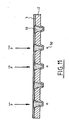
- FIG. 1 An example of a dispensing head 1 is illustrated in FIG. 1, as limited to its environment around a distribution well 10.
- Each well 10 has been etched by photolithography followed by a chemical wet etching in a silicon substrate 2 covered a membrane 3 and pyrex®, the membrane and the substrate are assembled by anodic welding to form the head 1.
- the well 10 has an inverted pyramidal shape, and passes right through the silicon substrate 2 according to four continuously inclined walls 11 and defined by the crystalline planes 1-1-1 of the silicon.
- the upper opening 12 of the well which communicates with the membrane 3, forms a square with an upper side at the side of the lower orifice 13 in order to accelerate the ejection of the droplets.
- a micro-channel 20 for supplying or discharging the well in reagent is machined in the membrane 3.
- the microchannel 13 communicates with a supply or storage tank 4 of reagent 5. It is also shown in this view that the substantially flat lower face 2i substrate 2 protrudes around the side walls 11 of the well 10 so as to extend these walls forming a nozzle 14. Such nozzles are obtained by machining the lower face.
- the height H of such a nozzle referred to the side C, side of the orifice 13, measures the aspect ratio of about 3 in the example, which improves the formation of micro-droplets of volume of the order of the picoliter .
- the value of the shape ratio is limited by technological constraints and a good compromise is to be sought between 1 and 20, depending on the material and the etching technique used.
- the average distance between two wells is typically about 550 ⁇ m.
- FIG. 4 The sectional view shown in FIG. 4, along the plane IV-IV of the preceding figure, clearly shows the independence of the reservoirs 4 allowing the distribution or the suction of different reagents 5a and 5b.
- FIGS. 5 and 6 show, respectively in a sectional view and in section along the VV plane, a dispensing head comprising sixteen wells 10 connected individually to sixteen tanks 4 by sixteen micro-channels 20.
- a dispensing head comprising sixteen wells 10 connected individually to sixteen tanks 4 by sixteen micro-channels 20.
- Such a configuration is advantageously used to distribute sixteen different reagents.
- the substantially flat bottom face 2i of the substrate 2 of the dispensing head of FIGS. 5 and 6 is shown in a cavalier view in FIG. 7 and in a variant in FIG. 8.
- the walls of the wells 10 project from under form of pyramids. This inclined form of walls is advantageous because the reagent is not likely to accumulate and therefore stagnate. Moreover from the hydrodynamic point of view, it allows a better flow with a distribution of pressures and speeds in a continuous manner.
- these same walls 11 appear in transparency in a cylindrical shape, of diameter equal to 100 microns, extended by a centered tip 6, which is also cylindrical and has a diameter of 20 microns.
- the membrane configuration illustrated in FIG. 9 is advantageously implemented.
- the membrane 3 has a single opening 30 which allows to feed or aspirate the same reagent on all the wells 4 without the use of micro-channels.
- This reagent is transported from or sucked to a remote reservoir (not shown) through a hose 7 coupled to a single microcapillary 40 passing through the membrane 3.
- the preceding membrane is partitioned by three penetrations 31 so as to form four independent conduits 32 supply or suction of reagents.
- These ducts are connected to four micro-capillaries 41 coupled, through the membrane 3 and four flexible pipes 7, to four remote reservoirs (not shown).
- Such a configuration is particularly suited to the distribution of the four basic nucleotides to form probes 9 for the preparation of microchips on a blade 82 coated with a silane layer 83 to allow the grafting of the first nuclides.
- the blade 82 is supported by a positioning device 86 along the XYZ axes.
- the membrane 3 is applied locally, as illustrated in the sectional view of FIG. Figure 11.
- the selective actuation of well 10 of distribution is caused by means locally deforming the membrane 3 by applying a force F ⁇ .
- FIGS. 12a and 12b the two phases of actuation of a well 10 by local deformation of the membrane actuated by electromagnetic triggering means are illustrated.
- These means are formed of an elementary electromagnet 60 composed of a current generator excitation circuit 61, in particular comprising a coil 63 coupled to an air gap core 64.
- the electromagnetic means also comprise a magnetized chip 65 fixed on the membrane 3 to the right of the well and likely to be polarized by the electromagnet.
- the pellet may alternatively be a permanent magnet, or a dia or paramagnetic material.
- the core 63 exerts a force of attraction F ⁇ at on the pellet 65.
- the membrane 3 is then deformed towards the electromagnet and the liquid 51 is stopped at the flow through the orifice 13 (FIG. 12a).
- the core 63 exerts a repulsive force F ⁇ r on the magnetized chip 65.
- the diaphragm is hollow deformed and the liquid 51 is expelled in the form of micro-droplets 50 through the orifice 13 of the ejection nozzle (FIG. 12b), with a volume calibrated and controlled by the dimensions of the nozzle as well as the amplitude and duration of the electrical signal applied.
- the droplet ejection can be done by applying electrical current pulses or by applying an alternating current to the resonance frequency proper to the membrane.
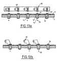
- FIGS. 13a and 13b illustrate in section such an assembly respectively formed by electromagnetic means and piezoelectric means.
- the electromagnetic means comprise electromagnets 60 and magnets 65, arranged in matrix form in line with each well 4, and the piezoelectric means comprise piezoelectric chips 70, coupled to excitation circuits 61 of the same type as those used for the means. electromagnetic.
- the piezoelectric triggering of micro-droplets 50 (FIG. 13b) is activated in the same way as in the case of electromagnetic tripping (FIGS. 12 and 13a) by closing the circuits 61, the opening of the switches 66 stopping the flow of the droplets 50
- the electrical signals are this time potential differences applied across the piezoelectric elements.
- the set of tripping means is managed by a control unit (not shown) programmable through a coupling or multiplexing network, the implementation of which falls within the field of competence of those skilled in the art.
- a control unit can trigger simultaneously or sequentially the aspiration or distribution of the same reagent or different reagents through the wells.
- reagents are sucked into a dispensing head as illustrated in the cross-sectional view of FIG. 14.
- the reagents are contained in microcuvettes. 80 engraved on a plate 81 in dimensions corresponding to that of the wells 4.
- This plate comprises in the example 9 600 micro-cuvettes spaced 0.6 mm. A few thousand cuvettes per cm 2 can also be made, while the titration plates currently used currently have only 1 to 4 cuvettes per cm 2 .
- the plate is moved micrometrically (Z direction) towards the substrate 2 to crush Teflon® seals 82 fixed on the edge of the microcuvettes 80.
- Teflon® seals 82 fixed on the edge of the microcuvettes 80.
- Other materials may be alternatively used to form the joints: silicone, vuiton®, polymer, elastomer or suitable thermoplastic material.
- the reagents are then sucked into the wells by triggering a pump 8 mounted on a discharge pipe 7 coupled to the well discharge pipes 4, as detailed above.
- the wafer 81 is also movable along the XY directions in order to provide other aspirations from other microcuvettes for mixing reagents in the same well.
- the plate is placed on an XYZ positioning table (shown in Figure 10).
- the reagents can be of various types: cDNA, oligonucleotides, genes, cells, mRNA, proteins, DNA or RNA sequences amplified by PCR (initials in English terminology of "Polymerization Chain Reaction"), antigens and antibodies, therapeutic molecules, serums, etc.
- oligonucleotides or proteins on a Titration wafer or on a moving blade is illustrated in the sectional view of FIG. 15.
- a dispensing head is fed with by tanks and the action of pumps according to Figure 10.
- Different therapeutic reagents 52 to 56 are distributed in the wells.
- Cells to be treated are deposited in the microcuvettes of a Titration Plate 81.
- the head and the plate are precisely aligned with reference marks (not shown).
- the plate of Titration is performed by injection of a thermoplastic material, such as polymethylmethacrylate or polycarbonate.
- the probes are formed at the programmatic request of the actuator management unit together with the displacement of the blade, which makes it possible to immediately form the probes during this displacement: the duration of formation of the probes 9 is optimized, allowing to save considerable time compared to the formation of successive layers of the state of the art.
- the high flow rate obtained with the distribution system according to the invention makes it possible to produce probes that can reach, for example, 60 to 70 nucleotides necessary for applications in functional genomics and gene expressions.
- the wafer or the blade is moved by micrometric adjustment in XY directions to position the orifices of the ejectors facing the areas to be printed.
- the blade 82 In another example of application to the detection of hybridization in the context of a genetic test, as shown in section in FIG. 16, the blade 82, prepared according to the preceding figure, is scanned by a flow of Patient DNA 90.
- the patient's DNA is first magnetically labeled by grafting beads 91, used in the state of the art to immobilize molecules in a magnetic field or, alternatively, by fluorescence.
- the additional advantage of the present solution is to reuse the distribution triggering means to perform the reading of the test by detection, which reduces the amount of electronic equipment used, whereas in the prior art, it is necessary to have reading coils in the titration cuvettes.
- Hybridization or immunological interaction makes it possible to fix the DNAs of the patient on some of the probes 9.
- the detection of these hybridizations is carried out by forming a current induced in the circuits 61 at the right of the hybridized probes or by optical detection. This detection is made possible because of the positioning accuracy of the probes and the in the case of a magnetic marking, it is the same circuits 61 which ensure the distribution of the probes and the detection of the hybridizations.
- the percutaneous administration of drugs is carried out, with reference to the sectional view of FIG. 17, from a print head to a dispensing well 4.
- a drug is dispensed according to the method set forth above.
- a voltage of a few millivolts is applied by a voltage generator circuit 61 to a piezoelectric cell 70 to deform the membrane 3.
- a precalibrated amount of drug 50 for a given time can thus be administered.
- Two of the opposing walls 11 of the well may also be polarized to facilitate absorption of the drug by causing the pores of the skin to expand.
- the micro-channels can also be etched on the substrate or on the membrane.
- the membrane or the substrate are made with a multilayer structure for integrating the micro-channels three-dimensionally in different layers.
- the micro-channels are then coupled to the wells by connections perpendicular to the upper openings of the wells.
- thermoelastic deformation of a bimetallic material arranged in the form of elementary bars at right of the wells on the membrane.
- Each strip may be formed of a layer of ferromagnetic material and a layer of conductive material (Cu, Al, Au, etc.), the ferromagnetic material being deforming under the effect of a magnetic field produced by the electromagnet. It is also possible to act by pneumatic means, by electro-vaporization, or by the application of electrostatic fields.
- the deformation forces of the membrane or its heating can be created, for example using eddy currents.
- the self-resonance may be effected by deformation of the membrane or by vibration of the end of the nozzle.
- the microcuvettes 80 of a Titration plate 81 are equipped with polarized electrodes 87.
- the cell reactivity test can be optical. that is to say by fluorescence and / or spectroscopy, or electric by measurement of electrical or electrochemical impedance. It is also possible to apply, conversely, a suitable potential difference between these electrodes to create a polarization in the cells and thus promote the therapeutic effect on cells.
- Another application of the distribution system according to the invention relates to the distribution of reagents in mass spectrometry columns for the characterization of compounds, by parallel or sequential feeding as described above. This application may also be suitable for chromatographs.
Abstract
Description
L'invention concerne un système de distribution parallèle et sélective, à haut rendement, de micro-gouttelettes de volume extrêmement réduit -de l'ordre d'un sous-multiple de nano-litre, voire d'un sous-multiple de pico-litre-, des cartouches transportables et un kit pour mettre en oeuvre une telle distribution, ainsi que les applications de ce système, notamment dans les domaines de la chimie, de la biologie, de la biotechnologie ou de la pharmacie, -en particulier pour la réalisation de bio-puces, pour des tests pharmaceutiques, immunologiques ou biochimiques, pour le criblage de chimiothèques ou de sérothèques, la préparation de médicaments ou leur administration percutanée par iono-phorèse, ou encore dans les domaines de la cosmétique, pour la réalisation de diffuseurs de parfums ou d'aérosols, de l'impression par jet d'encre ou de l'électronique automobile, en particulier dans les injecteurs de carburant ou de gas-oils.The invention relates to a system for parallel and selective distribution, with high efficiency, of micro-droplets of extremely small volume - of the order of a sub-multiple of nano-liter, or even a sub-multiple of pico- transportable cartridges and a kit for implementing such a distribution, as well as the applications of this system, in particular in the fields of chemistry, biology, biotechnology or pharmacy, in particular for production of biochips, for pharmaceutical, immunological or biochemical tests, for the screening of chemical libraries or serum libraries, the preparation of drugs or their percutaneous administration by ionophoresis, or in the fields of cosmetics, for the production of perfume or aerosol dispensers, inkjet printing or automotive electronics, in particular in fuel injectors or gas oils.
Les récents progrès en matière de recherche génomique et protéomique permettent de disposer d'un nombre considérable de molécules biologiques et thérapeutiques à tester. Cependant, les faibles quantités de produits biochimiques disponibles ainsi que leur coût élevé ont conduit à rechercher une augmentation sensible des capacités d'expérimentation par optimisation du rendement.Recent advances in genomic and proteomic research make it possible to have a considerable number of biological and therapeutic molecules to test. However, the small quantities of available biochemicals and their high cost have led to a significant increase in experimental capacity by optimizing yield.
Pour ce faire, différentes techniques ont été appliquées à la manipulation de liquides biochimiques, tels que les systèmes de repiquage ou de micro-pipetage avec des actionneurs piézoélectriques et, plus récemment, la technique d'impression par jet d'encre.To do this, various techniques have been applied to the handling of biochemical liquids, such as subculture or micro-pipetting systems with piezoelectric actuators and, more recently, the inkjet printing technique.
Le but dé ces technologies est la préparation de bio-puces par l'impression de sondes biologiques (d'oligonucléotides, protéines, peptides, etc..), pré-synthétisées dans la majorité des cas, sur une surface de différents types de support, tels que verre, nylon® ou cellulose®.The goal of these technologies is the preparation of bio-chips by the printing of biological probes (of oligonucleotides, proteins, peptides, etc.), pre-synthesized in the majority of the cases, on a surface of different types of support , such as glass, nylon® or cellulose®.
Il est par exemple connu des documents US 5,053,100 ou US 6,083,762, des pipetages qui utilisent un actionneur piézoélectrique sur une micro-pipette. Cette technique permet l'impression d'oligonucléotides pré-synthétisés ou synthétisés in situ. Cependant, ces systèmes sont fabriqués à l'unité et sont inaptes à la distribution parallèle à haute densité.For example, documents US Pat. No. 5,053,100 or US Pat. No. 6,083,762 disclose pipetting which uses a piezoelectric actuator on a micro-pipette. This technique allows the printing of oligonucleotides pre-synthesized or synthesized in situ. However, these systems are made individually and are not suitable for high density parallel distribution.
Dans le document US 6,028,189, la distribution de réactifs est effectuée par l'utilisation de micro-pompes de type à jet d'encre, activées par un actionneur piézoélectrique. Chaque micro-pompe est réalisée dans un bloc de silicium, avec des canaux d'alimentation et d'éjection des gouttelettes. Afin de réaliser des synthèses in situ, quatre micro-pompes délivrent des bases d'ADN par éjection dans des puits circulaires, formés sur un substrat de verre commandé en déplacement selon deux axes.In US 6,028,189, the reagent distribution is carried out by the use of micro-pumps of the ink jet type, activated by a piezoelectric actuator. Each micro-pump is made in a silicon block, with supply channels and ejection of the droplets. In order to carry out in situ synthesis, four micro-pumps deliver DNA bases by ejection into circular wells, formed on a glass substrate controlled in two-axis displacement.
L'article du journal Analytical Chemistry, vol 70, n° 22, 15 novembre 1998, pages 4755 à 4760, décrit un micro-distributeur de gouttelettes dans lequel la déformation d'un élément bimorphe piézocéramique entraîne, par l'intermédiaire de billes de flexiglass, la déformation d'une membrane qui produit l'écoulement de liquide à travers un puits situé en regard. Cette technique suppose un bon contrôle de la déformation de l'élément piézocéramique et de la membrane.The article in the Journal Analytical Chemistry,
Ces systèmes ne permettent pas de réaliser une impression à très haut rendement au sens de la présente invention, c'est-à-dire quelques centaines à quelques milliers de gouttes par cm2 : avec quatre pompes opérant à quelques centaines de Hz, une machine selon le document précédent imprimerait 100 000 gouttes en quelques centaines de secondes. La synthèse de sondes de 25 oligonucléotides nécessiterait alors plus de 2 heures.These systems do not make it possible to produce a very high efficiency printing within the meaning of the present invention, that is to say a few hundred to a few thousand drops per cm 2 : with four pumps operating at a few hundred Hz, a machine according to the previous document would print 100,000 drops in a few hundred seconds. The synthesis of oligonucleotide probes would then require more than 2 hours.
L'invention vise à permettre une augmentation considérable du rendement de distribution sélective de micro-gouttelettes, par une forte augmentation de la densité d'impressions parallèles, comparable aux densités obtenues par la photochimie pour l'immobilisation de molécules spécifiques à travers des masques de photolithographie. Cette méthode est limitée aux molécules pouvant être fixées par photochimie et ne permet fondamentalement pas de manipuler individuellement des gouttelettes de réactifs. De plus, la synthèse in situ, par cette méthode, est limitée à environ 25 mononucléotides. Un autre but de l'invention est de permettre de réaliser une sélectivité non seulement spatiale, en permettant de distribuer le réactif sur des sites prédéterminés ou programmés, mais également ciblée en distribuant un réactif sélectionné parmi plusieurs sur le site prédéterminé.The aim of the invention is to allow a considerable increase in the yield of selective distribution of micro-droplets, by a sharp increase in the density of parallel prints, comparable to the densities obtained by photochemistry for the immobilization of specific molecules through masks of photolithography. This method is limited to molecules that can be fixed by photochemistry and basically does not allow individual handling of reagent droplets. In addition, in situ synthesis by this method is limited to about 25 mononucleotides. Another object of the invention is to make it possible to achieve not only spatial selectivity, by making it possible to distribute the reagent on predetermined or programmed sites, but also targeted by distributing a selected reagent among several at the predetermined site.
L'invention vise également à réaliser un système multifonctionnel et facile à adapter sous différentes formes, par exemple sous forme de kits miniatures d'analyse biologique ou biochimique pour permettre un grand nombre d'applications. En particulier, l'invention permet de ne pas se limiter à la synthèse de 25 nucléotides par sonde mais de synthétiser des sondes longues pouvant atteindre, par exemple, 70 nucléotides, tout en conservant un rendement élevé.The invention also aims to achieve a multifunctional system and easy to adapt in different forms, for example in the form of miniature kits for biological or biochemical analysis to allow a large number of applications. In particular, the invention makes it possible not to be limited to the synthesis of 25 nucleotides per probe but to synthesize long probes of up to, for example, 70 nucleotides, while maintaining a high yield.
Ces buts sont atteints en utilisant une tête d'impression dans laquelle est réalisée, par des techniques de type microélectroniques à haute densité, une matrice de puits de forme particulière et alimentés suivant une connectique spécifique pour une distribution sélective à haut débit.These objects are achieved by using a print head in which is made, by high density microelectronic type techniques, a matrix of wells of particular shape and powered by a specific connectivity for a high-speed selective distribution.
Plus précisément, l'invention a pour objet un système de distribution de micro-gouttelettes tel que défini par la revendication 1.More specifically, the subject of the invention is a micro-droplet distribution system as defined by claim 1.
Selon l'invention, il convient de comprendre par distribution l'éjection ou l'aspiration de micro-gouttelettes, par haut rendement de quelques dizaines à quelques milliers de micro-gouttelettes distribuées parallèlement en une fraction de seconde, par paroi à symétrie axiale une paroi de révolution ou cylindrique, par exemple de section carrée, et par rapport de forme le rapport entre la hauteur et l'ouverture de la buse de sortie.According to the invention, it is appropriate to understand by distribution the ejection or aspiration of micro-droplets, in high yield from a few tens to a few thousand micro-droplets distributed in parallel in a fraction of a second, per wall with axial symmetry a wall of revolution or cylindrical, for example of square section, and in relation to form the ratio between the height and the opening of the outlet nozzle.
Pour atteindre ce type de rendement, le substrat présente une densité de puits pouvant atteindre 10 000 par cm2, avec un débit pouvant dépasser 1 million de gouttelettes à la seconde.To achieve this type of yield, the substrate has a well density of up to 10,000 per cm 2 , with a flow rate of more than 1 million droplets per second.
Avantageusement, le matériau du substrat est choisi parmi les matériaux semi-conducteurs tels que le silicium, l'arséniure de gallium, le carbure de silicium, le germanium, les composites d'oxydes et d'isolant (tels que le SOI, initiales de silicium-oyde-isolant), les verres, les nitrures de silicium, le polysilicium, les céramiques, les matériaux thermoplastiques, -tels que le polyméthacrylate de méthyle, les polycarbonates, le polytetrafluoroethylene, le chlorure de polyvinyle ou le polydimethylsiloxane, les résines photosensibles épaisses ( par exemple la résine « SU8 »)-, ainsi que les métaux, tels que le tungstène ou les aciers inoxydables.Advantageously, the material of the substrate is chosen from semiconductor materials such as silicon, gallium arsenide, silicon carbide, germanium, oxide and insulator composites (such as SOI, initials of silicon-oyde-insulator), glasses, silicon nitrides, polysilicon, ceramics, thermoplastic materials, such as polymethyl methacrylate, polycarbonates, polytetrafluoroethylene, polyvinyl chloride or polydimethylsiloxane, photosensitive resins thick (for example the resin "SU8") - as well as metals, such as tungsten or stainless steels.
De manière préférée, les techniques de micro-fabrication pour réaliser les puits ou les micro-canaux sont choisies en fonction du matériau du substrat :
- gravures chimiques humides ou sèches telles que la gravure ionique réactive (en abrégé RIE) ou la gravure profonde (en abrégé D-RIE) pour le silicium et verre ;
- gravure par électroérosion ou électroformage pour les métaux ;
- moulage et polymérisation pour les matériaux thermoplastiques ;
- photolithographie, découpage au laser, ultrasons, ou par projection d'abrasifs pour la plupart des substrats.
- wet or dry chemical etchings such as reactive ion etching (abbreviated RIE) or deep etching (abbreviated D-RIE) for silicon and glass;
- electro-erosion or electroforming engraving for metals;
- molding and polymerization for thermoplastic materials;
- photolithography, laser cutting, ultrasound, or blasting abrasives for most substrates.
Selon des modes préférés, le matériau de la membrane est choisi entre le verre, le silicium, les élastomères et les matériaux thermoplastiques; la membrane peut être gravée par les techniques de gravure citées plus haut, afin de réaliser un réseau de micro-canaux d'alimentation des puits, ces micro-canaux étant couplés en extrémité à au moins un réservoir d'alimentation en réactif.In preferred embodiments, the membrane material is selected from glass, silicon, elastomers and thermoplastic materials; the membrane may be etched by the etching techniques mentioned above, in order to produce a micro-channel supply network of the wells, these microchannels being end-coupled to at least one reagent supply tank.
Dans des modes de réalisation particuliers, les moyens de déformation locale de la membrane sont constitués par des actionneurs électromagnétiques, magnétostrictifs ou piézoélectriques. Des moyens alternatifs sont également prévus tels que les moyens thermiques de type jet d'encre ou thermoélastiques par effet de type bilame, l'électro-vaporisation produit par un champ électrique localisé entre chaque puits, ou encore des actionneurs électrostatiques.In particular embodiments, the local deformation means of the membrane are constituted by electromagnetic, magnetostrictive or piezoelectric actuators. Alternative means are also provided such as thermal means of ink-jet type or thermoelastic effect bimetallic type, electro-vaporization produced by an electric field located between each well, or electrostatic actuators.
L'ensemble des moyens de déformation peut être géré par une unité de commande programmable à travers un réseau de multiplexage. Une telle unité permet de déclencher simultanément ou successivement l'aspiration ou la distribution de réactifs identiques ou différents à travers tous les puits, à travers des blocs de puits ou certains puits.The set of deformation means can be managed by a programmable control unit through a multiplexing network. Such a unit makes it possible to simultaneously or successively trigger the aspiration or the distribution of identical or different reagents through all the wells, through well blocks or certain wells.
Selon des modes de réalisation particuliers, la tête d'impression possède quatre ou un multiple de quatre lignes et un nombre de colonnes de puits adapté à la densité souhaitée, afin de procéder à la synthèse de sondes d'ADN à partir des quatre monomères de base des nucléotides pour la préparation de bio-puces. Les puits de chaque ligne sont alimentés par un même réservoir à travers un micro-canal formé dans la membrane parallèlement à la ligne de puits et couplé latéralement à la ligne ou orthogonalement au plan du substrat, les réservoirs étant gravés dans la membrane ou disposés à distance et reliés aux micro-canaux par des connexions souples.According to particular embodiments, the print head has four or a multiple of four lines and a number of well columns adapted to the desired density, in order to proceed to the synthesis of DNA probes from the four monomers of nucleotide base for the preparation of biochips. The wells of each line are fed by a same reservoir through a micro-channel formed in the membrane parallel to the well line and coupled laterally to the line or orthogonal to the plane of the substrate, the reservoirs being etched in the membrane or arranged to distance and connected to micro-channels by flexible connections.
L'invention concerne également les applications de la tête d'impression définie ci-dessus. Pour mettre en oeuvre au moins certaines d'entre elles, il est avantageux de préparer un ensemble prêt à l'emploi sous forme de :
- cartouche de distribution comprenant au moins une tête d'impression préremplie de réactifs et de plaquettes de titration en matériau semi-conducteur ou thermoplastique, pouvant présenter des micro-cuvettes formées par gravure de type micro-électronique, par usinage, par moulage, par thermoformage, ou toute technique adaptée à une telle fabrication ;
- kit de distribution comprenant au moins une tête d'impression, pouvant être équipée d'au moins une pompe d'aspiration, et au moins une plaquette de Titration, préremplies ou non de réactif.
- dispensing cartridge comprising at least one pre-filled printhead of reagents and titration plates made of semiconductor or thermoplastic material, which may have microcuvettes formed by microelectronic-type etching, by machining, by molding, by thermoforming , or any technique adapted to such manufacture;
- distribution kit comprising at least one print head, which can be equipped with at least one suction pump, and at least one Titration wafer, pre-filled or not with reagent.
Ces cartouches ou ces kits sont plus particulièrement destiné(e)s à la préparation de bio-puces, par synthèse in situ ou dépôt d'oligonucléotides pré-synthétisés, au criblage collectif ou individuel sur molécules biologiques ou sur cellules, à la préparation de médicaments ou aux tests pharmaceutiques ou de dépistage immunologique, biochimiques et biologiques.These cartridges or kits are more particularly intended for the preparation of biochips, by in situ synthesis or deposition of pre-synthesized oligonucleotides, by collective or individual screening on biological molecules or cells, in the preparation of drugs or pharmaceutical or immunoassay, biochemical and biological tests.
L'administration percutanée de médicaments par iono-phorèse peut être réalisée à partir d'une tête d'impression définie précédemment comportant un plusieurs puits. Un système d'application d'une différence de potentiel adéquate sur une cellule piézoélectrique, ou tout moyen de déclenchement électromagnétique, forme un dispositif d'administration d'une quantité calibrée d'au moins un médicament contenu ou formé dans ce puits.Percutaneous administration of drugs by ionophoresis can be carried out from a previously defined print head comprising a plurality of wells. A system for applying a suitable potential difference on a piezoelectric cell, or any electromagnetic trigger means, forms a device for delivering a calibrated quantity of at least one drug contained or formed in this well.
Outre les applications citées plus haut, l'invention peut également être utilisée pour la séparation et le tri, par exemple en chromatographie par filtration sélective. Sur les parois des puits d'une tête d'impression selon l'invention sont d'abord fixées, greffées, bloquées ou accrochées, par tout moyen connu, des bio-cellules identiques ou différentes par puits ou par blocs de puits. La tête d'impression peut être intégrée à l'embout d'une seringue.In addition to the applications mentioned above, the invention can also be used for separation and sorting, for example by selective filtration chromatography. On the walls of the wells of a printing head according to the invention are first fixed, grafted, blocked or hooked, by any known means, identical or different bio-cells per well or well blocks. The print head can be integrated into the tip of a syringe.
D'autres caractéristiques, avantages et applications apparaîtront également dans la suite de la description qui détaille, plus particulièrement, des exemples de mise en oeuvre non limitatifs de la présente invention, en référence aux figures annexées qui représentent, respectivement :
- la figure 1, une vue schématique partielle en perspective d'une tête de distribution limitée à l'environnement d'un puits de base d'un système selon l'invention ;
- la figure 2, une vue en coupe selon II-II de la tête selon la figure 1 avec un réservoir de remplissage ;
- la figure 3, une vue schématique en perspective d'une tête de distribution d'un système selon l'invention à huit puits de distribution ;
- la figure 4, une vue en coupe selon IV-IV de la figure précédente ;
- la figure 5, une vue schématique en perspective d'une tête de distribution d'un système selon l'invention à seize puits de distribution ;
- la figure 6, une vue en coupe selon V-V de la figure précédente ;
- les figures 7 et 8, deux vues cavalières de la face inférieure de la tête de distribution du système selon la figure 5 et selon une variante ;
- la figure 9, une vue en perspective du système selon la figure 5 avec des moyens de distribution d'un réactif à distance;
- la figure 10, une vue en perspective du système selon la figure 5 avec des moyens de distribution à distance de quatre mononucléides pour former des sondes sur une lame mobile ;
- la figure 11, une vue en coupe schématique d'un système de distribution selon l'invention illustrant le principe d'actionnement sélectif des puits de distribution ;
- les figures 12a et 12b, des vues en coupe illustrant les deux phases d'actionnement d'un puits par des moyens électromagnétiques de déclenchement sélectif ;
- les figures 13a et 13b, une vue en coupe d'un système de distribution selon l'invention, illustrant l'actionnement sélectif respectivement par des moyens électromagnétiques et des moyens piézoélectriques de déclenchement sélectif;
- la figure 14, une vue en coupe d'une tête de distribution en phase de remplissage par aspiration de réactifs pour la préparation d'une cartouche de distribution selon l'invention ;
- la figure 15, une vue en coupe d'un système de distribution selon l'invention appliqué au traitement de cellules sur une plaquette de titration ;
- la figure 16, une vue en coupe d'un système de distribution selon l'invention appliqué à la détection d'hybridation dans le cadre d'un test génétique;
- la figure 17, une vue en coupe d'un système de distribution selon l'invention appliquée à l'administration percutanée de médicaments.
- Figure 1 is a partial schematic perspective view of a dispensing head limited to the environment of a basic well of a system according to the invention;
- Figure 2, a sectional view along II-II of the head according to Figure 1 with a filling tank;
- Figure 3 is a schematic perspective view of a dispensing head of a system according to the invention with eight distribution wells;
- Figure 4, a sectional view along IV-IV of the previous figure;
- Figure 5 is a schematic perspective view of a dispensing head of a system according to the invention to sixteen distribution wells;
- Figure 6, a sectional view along VV of the previous figure;
- Figures 7 and 8, two views of the lower face of the distribution head of the system according to Figure 5 and in a variant;
- Figure 9 is a perspective view of the system according to Figure 5 with means for dispensing a remote reagent;
- Figure 10 is a perspective view of the system according to Figure 5 with means for remote distribution of four mononuclides to form probes on a movable blade;
- Figure 11 is a schematic sectional view of a dispensing system according to the invention illustrating the principle of selective actuation of the distribution wells;
- Figures 12a and 12b, sectional views illustrating the two phases of actuation of a well by electromagnetic means of selective tripping;
- Figures 13a and 13b, a sectional view of a dispensing system according to the invention, illustrating the selective actuation respectively by electromagnetic means and selective tripping piezoelectric means;
- FIG. 14 is a sectional view of a dispensing head during the filling phase by suction of reagents for the preparation of a dispensing cartridge according to the invention;
- Figure 15 is a sectional view of a dispensing system according to the invention applied to the treatment of cells on a titration wafer;
- Figure 16, a sectional view of a dispensing system according to the invention applied to the detection of hybridization in the context of a genetic test;
- Figure 17, a sectional view of a dispensing system according to the invention applied to the transdermal administration of drugs.
Sur toutes les figures, des signes de référence identiques désignent des éléments identiques ou techniquement équivalents. Les membranes apparaissent en transparence afin de faciliter la visualisation de l'ensemble des éléments représentés.In all the figures, identical reference signs designate identical or technically equivalent elements. The membranes appear in transparency in order to facilitate the visualization of all the elements represented.
Un exemple de tête de distribution 1 est illustré en figure 1, telle que limitée à son environnement autour d'un puits de distribution 10. Chaque puits 10 a été gravé par photolithographie suivie d'une gravure humide chimique dans un substrat de silicium 2 recouvert d'une membrane 3 en pyrex® , la membrane et le substrat sont assemblés par soudure anodique pour former la tête 1.An example of a dispensing head 1 is illustrated in FIG. 1, as limited to its environment around a
Le puits 10 possède une forme pyramidale inversée, et traverse de part en part le substrat de silicium 2 selon quatre parois continûment inclinées 11 et définies par les plans cristallins 1-1-1 du silicium. L'ouverture supérieure 12 du puits, qui communique avec la membrane 3, forme un carré de côté supérieur au côté de l'orifice inférieure 13 afin d'accélérer l'éjection des gouttelettes. Un micro-canal 20 d'alimentation ou d'évacuation du puits en réactif est usiné dans la membrane 3.The well 10 has an inverted pyramidal shape, and passes right through the
Dans cet exemple de réalisation, les dimensions de puits sont les suivantes :
- côté de l'ouverture supérieure: 500µm
- côté de l'orifice inférieur: entre 10 et 50 µm (environ 30 µm)
- épaisseur de la membrane : 10 à 50 µm
- épaisseur du substrat : 360 µm
- side of the top opening: 500μm
- side of the lower orifice: between 10 and 50 μm (approximately 30 μm)
- thickness of the membrane: 10 to 50 μm
- substrate thickness: 360 μm
En vue en coupe selon la figure 2 selon II-II, il apparaît que le micro-canal 13 communique avec un réservoir d'alimentation ou de stockage 4 de réactif 5. Il est également montré sur cette vue que la face inférieure 2i sensiblement plane du substrat 2 forme saillie autour des parois latérales 11 du puits 10 de manière à prolonger ces parois en formant une buse 14. De telles buses sont obtenues par usinage de la face inférieure. La hauteur H d'une telle buse rapportée au côté C, côté de l'orifice 13, mesure le rapport de forme environ égal à 3 dans l'exemple, qui améliore la formation de micro-gouttelettes de volume de l'ordre du picolitre. La valeur du rapport de forme est limitée par des contraintes technologiques et un bon compromis est à rechercher entre 1 et 20, suivant le matériau et la technique de gravure utilisés. Par ailleurs, la distance moyenne entre deux puits est typiquement d'environ 550 µm.In sectional view according to FIG. 2 along II-II, it appears that the
Sur la figure 3, la vue en perspective d'une tête de distribution 1 comporte huit puits 10 reliés individuellement à huit réservoirs 4 par huit micro-canaux 20. Les dimensions typiques d'une telle tête sont :
- longueur : 3mm
- largeur : 5mm
- épaisseur : 1 mm selon épaisseur des réservoirs
- length: 3mm
- width: 5mm
- thickness: 1 mm according to the thickness of the tanks
La vue en coupe représentée en figure 4, selon le plan IV-IV de la figure précédente, montre bien l'indépendance des réservoirs 4 permettant la distribution ou l'aspiration de réactifs différents 5a et 5b.The sectional view shown in FIG. 4, along the plane IV-IV of the preceding figure, clearly shows the independence of the reservoirs 4 allowing the distribution or the suction of
En variante, les figures 5 et 6 montrent, respectivement en vue cavalière et en coupe selon le plan V-V, une tête de distribution comportant seize puits 10 reliés individuellement à seize réservoirs 4 par seize micro-canaux 20. Une telle configuration est avantageusement utilisée pour distribuer seize réactifs différents.As a variant, FIGS. 5 and 6 show, respectively in a sectional view and in section along the VV plane, a dispensing head comprising sixteen
La face inférieure 2i sensiblement plane du substrat 2 de la tête de distribution des figures 5 et 6, est représentée en vue cavalière sur la figure 7 et en variante sur la figure 8. En figure 7, les parois des puits 10 apparaissent en saillie sous forme de pyramides. Cette forme inclinée des parois est avantageuse car le réactif ne risque pas de s'accumuler et donc de stagner. Par ailleurs du point de vue hydrodynamique, elle permet un meilleur écoulement avec une répartition des pressions et des vitesses de manière continue. En figure 8, ces mêmes parois 11 apparaissent en transparence sous une forme cylindrique, de diamètre égal à 100 microns, prolongée par un embout centré 6, également cylindrique et de diamètre de 20 microns.The substantially
Lorsqu'un seul réactif est distribué ou aspiré simultanément à travers les puits, la configuration de membrane illustrée en figure 9 est avantageusement mise en oeuvre. Dans cette configuration, la membrane 3 possède une ouverture unique 30 qui permet d'alimenter ou d'aspirer un même réactif sur tous les puits 4 sans l'utilisation de micro-canaux. Ce réactif est transporté depuis ou aspiré vers un réservoir distant (non représenté) à travers un tuyau souple 7 couplé à un micro-capillaire unique 40 traversant la membrane 3.When a single reagent is dispensed or sucked simultaneously through the wells, the membrane configuration illustrated in FIG. 9 is advantageously implemented. In this configuration, the
Lorsque plusieurs réactifs sont distribués, par exemple quatre mononucléides A, C, T, G, dans le cas illustré par la vue en perspective de la figure 10, la membrane précédente est cloisonnée par trois traversées 31 de manière à former quatre conduits indépendants 32 d'alimentation ou d'aspiration des réactifs. Ces conduits sont reliés à quatre micro-capillaires 41 couplées, à travers la membrane 3 et quatre tuyaux souples 7, à quatre réservoirs distants (non représentés). Une telle configuration est particulièrement adaptée à la distribution des quatre nucléotides de base pour former des sondes 9 pour la préparation de micro-puces sur une lame 82 recouverte d'une couche de silane 83 pour permettre le greffage des premiers nucléides. La lame 82 est supportée par un dispositif de positionnement 86, selon les axes XYZ.When several reagents are distributed, for example four mononuclides A, C, T, G, in the case illustrated by the perspective view of FIG. 10, the preceding membrane is partitioned by three
Dans le but de distribuer le ou les réactifs par micro-gouttellettes 50 de manière sélective, c'est-à-dire en sollicitant chaque puits indépendamment les uns des autres, la membrane 3 est sollicitée localement, comme illustré sur la vue en coupe de la figure 11. L'actionnement sélectif des puits 10 de distribution est provoqué par des moyens déformant localement la membrane 3 par application d'une force ![]()
![]()
Sur les vues en coupe des figures 12a et 12b, les deux phases d'actionnement d'un puits 10 par déformation locale de la membrane actionnés par des moyens électromagnétiques de déclenchement sont illustrés. Ces moyens sont formés d'un électroaimant élémentaire 60 composé d'un circuit d'excitation 61 générateur de courant, comprenant notamment une bobine 63 couplée à un noyau d'entrefer 64. Les moyens électromagnétiques comprennent également une pastille aimantée 65 fixée sur la membrane 3 au droit du puits et susceptible d'être polarisée par l'électroaimant. La pastille peut alternativement être un aimant permanent, ou en matériau dia ou paramagnétique.In the sectional views of FIGS. 12a and 12b, the two phases of actuation of a well 10 by local deformation of the membrane actuated by electromagnetic triggering means are illustrated. These means are formed of an
Lorsque le courant 62 circule, le noyau 63 exerce une force d'attraction ![]()
![]()
![]()
![]()
Alternativement, l'éjection de gouttelettes peut se faire par application d'impulsions de courant électrique ou par application d'un courant altematif à la fréquence de résonance propre de la membrane.Alternatively, the droplet ejection can be done by applying electrical current pulses or by applying an alternating current to the resonance frequency proper to the membrane.
Afin de réaliser une distribution sélective de micro-gouttelettes, c'est-à-dire dont la commande est individualisée au niveau de chaque puits, la déformation locale est réalisée par un ensemble de moyens de déclenchement. Les figures 13a et 13b illustrent en coupe un tel ensemble formé respectivement par des moyens électromagnétiques et des moyens piézoélectriques.In order to achieve a selective distribution of micro-droplets, that is to say whose control is individualized at each well, the local deformation is performed by a set of triggering means. Figures 13a and 13b illustrate in section such an assembly respectively formed by electromagnetic means and piezoelectric means.
Les moyens électromagnétiques comprennent des électroaimants 60 et des aimants 65, disposés sous forme matricielle au droit de chaque puits 4, et les moyens piézoélectriques comprennent des pastilles piézoélectriques 70, couplées à des circuits d'excitation 61 du même type que ceux utilisés pour les moyens électromagnétiques. Le déclenchement piézoélectrique de micro-gouttelettes 50 (figure 13b) est activé de la même façon que dans le cas de déclenchement électromagnétique (figures 12 et 13a) par fermeture des circuits 61, l'ouverture des interrupteurs 66 arrêtant l'écoulement des gouttelettes 50. Dans le cas de l'utilisation d'actionneurs piézoélectriques, les signaux électriques sont cette fois-ci des différences de potentielles appliquées aux bornes des éléments piézoélectriques.The electromagnetic means comprise
L'ensemble des moyens de déclenchement est géré par une unité de commande (non représentée) programmable à travers un réseau de couplage ou de multiplexage, dont la mise en oeuvre relève du domaine de compétence de l'homme de l'art. Une telle unité permet de déclencher simultanément ou successivement l'aspiration ou la distribution d'un même réactif ou de réactifs différents à travers les puits.The set of tripping means is managed by a control unit (not shown) programmable through a coupling or multiplexing network, the implementation of which falls within the field of competence of those skilled in the art. Such a unit can trigger simultaneously or sequentially the aspiration or distribution of the same reagent or different reagents through the wells.
Il est ainsi possible d'obtenir un débit d'éjection de gouttelettes élevé, par exemple 100 gouttelettes par seconde pour un même puits. Il est ainsi possible d'atteindre le débit de 100 000 pour une tête d'impression de 1000 puits, avec une déformation de la membrane contrôlé par le signal extérieure. En effet, le liquide étant quasiment incompressible, le rapport entre les vitesses de déplacement du liquide entre l'ouverture supérieure et l'orifice d'éjection du puits est inversement proportionnel au rapport des surfaces respectives. Dans l'exemple illustré, le rapport des côtés des orifices étant d'environ 15, la vitesse d'éjection des gouttelettes est donc environ 15 fois supérieure à celle de déformation des membranes.It is thus possible to obtain a high droplet ejection rate, for example 100 droplets per second for the same well. It is thus possible to reach the flow rate of 100,000 for a 1000-well printhead, with a deformation of the membrane controlled by the external signal. Indeed, since the liquid is almost incompressible, the ratio between the liquid displacement speeds between the upper opening and the well ejection orifice is inversely proportional to the ratio of the respective surfaces. In the example illustrated, the ratio of the sides of the orifices being approximately 15, the ejection speed of the droplets is thus about 15 times greater than that of deformation of the membranes.
Pour la préparation d'une cartouche de distribution selon l'invention, des réactifs sont aspirés dans une tête de distribution comme illustré sur la vue en coupe de la figure 14. Pour effectuer une telle aspiration, les réactifs sont contenus dans des micro-cuvettes 80 gravées sur une plaque 81 selon des dimensions correspondantes à celle des puits 4. Cette plaque comporte dans l'exemple 9 600 micro-cuvettes espacées de 0,6 mm. Quelques milliers de cuvettes par cm2 peuvent également être réalisées, alors que les plaques de titration couramment utilisées ne comportent actuellement que 1 à 4 cuvettes par cm2.For the preparation of a dispensing cartridge according to the invention, reagents are sucked into a dispensing head as illustrated in the cross-sectional view of FIG. 14. To carry out such an aspiration, the reagents are contained in microcuvettes. 80 engraved on a
La plaque est déplacée par réglage micrométrique (direction Z) vers le substrat 2 jusqu'à écraser des joints d'étanchéité en téflon® 82 fixés en bordure des micro-cuvettes 80. D'autres matériaux peuvent être alternativement utilisés pour former les joints : en silicone, vuiton®, en polymère, élastomère ou matériau thermoplastique adapté.The plate is moved micrometrically (Z direction) towards the
Les réactifs sont alors aspirés dans les puits par le déclenchement d'une pompe 8 montée sur un tuyau d'évacuation 7 couplé aux conduits d'évacuation des puits 4, comme détaillé ci-dessus. La plaquette 81 est également mobile selon les directions XY afin de prévoir d'autres aspirations à partir d'autres micro-cuvettes permettant d'effectuer des mélanges de réactifs dans un même puits. La plaque est placée sur une table de positionnement XYZ (représentée en figure 10).The reagents are then sucked into the wells by triggering a pump 8 mounted on a discharge pipe 7 coupled to the well discharge pipes 4, as detailed above. The
Suivant les applications, les réactifs peuvent être de type varié : ADNc, oligonucléotides, gènes, cellules, ARNm, protéines, séquences d'ADN ou d'ARN amplifiées par PCR (initiales en terminologie anglaise de « Polymerization Chain Reaction »), antigènes et anticorps, molécules thérapeutiques, sérums, etc.Depending on the application, the reagents can be of various types: cDNA, oligonucleotides, genes, cells, mRNA, proteins, DNA or RNA sequences amplified by PCR (initials in English terminology of "Polymerization Chain Reaction"), antigens and antibodies, therapeutic molecules, serums, etc.
En vue de la préparation de sondes pour réaliser une bio-puce, le dépôt d'oligonucléotides ou de protéines sur une plaquette de Titration ou sur une lame mobile est illustré sur la vue en coupe de la figure 15. Une tête de distribution est alimentée par des réservoirs et l'action de pompes conformément à la figure 10. Des réactifs thérapeutiques différents 52 à 56 sont distribués dans les puits. Des cellules à traiter 15 sont déposées dans les micro-cuvettes d'une plaque de Titration 81. La tête et la plaque sont alignées avec précision à l'aide de repères (non représentés). La plaque de Titration est réalisée par injection d'un matériau thermoplastique, tel que du polyméthacrylate de méthyle ou un polycarbonate.For the preparation of probes for making a bio-chip, the deposition of oligonucleotides or proteins on a Titration wafer or on a moving blade is illustrated in the sectional view of FIG. 15. A dispensing head is fed with by tanks and the action of pumps according to Figure 10. Different
Les sondes sont formées à la demande par programmation de l'unité de gestion des actionneurs conjointement avec le déplacement de la lame, ce qui permet de former immédiatement les sondes lors de ce déplacement : la durée de formation des sondes 9 est optimisée, permettant de gagner un temps considérable par rapport à la formation par couches successives de l'état de la technique. Le haut débit obtenu avec le système de distribution selon l'invention permet de réaliser des sondes pouvant atteindre par exemple 60 à 70 nucléotides nécessaires pour les applications en génomique fonctionnelle et expressions de gènes. La plaquette ou la lame est déplacé par réglage micrométrique selon des directions XY pour positionner les orifices des éjecteurs en regard avec les zones à imprimer.The probes are formed at the programmatic request of the actuator management unit together with the displacement of the blade, which makes it possible to immediately form the probes during this displacement: the duration of formation of the
Dans un autre exemple d'application à la détection d'hybridation dans le cadre d'un test génétique, tel qu'illustré en coupe sur la figure 16, la lame 82, préparée selon la figure précédente, est balayée par un flux d'ADN de patient 90. L'ADN du patient est au préalable marqué magnétiquement par greffage de billes 91, utilisé dans l'état de la technique pour immobitiser des molécules dans un champ magnétique ou, alternativement, par fluorescence.In another example of application to the detection of hybridization in the context of a genetic test, as shown in section in FIG. 16, the
L'avantage supplémentaire de la présente solution est de réutiliser les moyens de déclenchement de distribution pour réaliser la lecture du test par détection, ce qui permet de réduire la quantité de matériel électronique utilisé, alors que, dans l'art antérieur, il est nécessaire de disposer de bobines de lecture dans les cuvettes de titrage.The additional advantage of the present solution is to reuse the distribution triggering means to perform the reading of the test by detection, which reduces the amount of electronic equipment used, whereas in the prior art, it is necessary to have reading coils in the titration cuvettes.
L'hybridation ou l'interaction immunologique permet de fixer les ADN du patient sur certaines des sondes 9. La détection de ces hybridations est réalisée par formation d'un courant induit dans les circuits 61 au droit des sondes hybridées ou par détection optique. Cette détection est rendue possible du fait de la précision de positionnement des sondes et du fait, dans le cas d'un marquage magnétique, que ce sont les mêmes circuits 61 qui assurent la distribution des sondes et la détection des hybridations.Hybridization or immunological interaction makes it possible to fix the DNAs of the patient on some of the
Dans l'application iono-phorétique, l'administration percutanée de médicaments est réalisée, en référence à la vue en coupe de la figure 17, à partir d'une tête d'impression à un puits 4 de distribution. Dans ce puits, un médicament est distribué conformément à la méthode exposée ci-dessus. Une tension de quelques millivolts est appliquée par un circuit générateur de tension 61 sur une cellule piézoélectrique 70 afin de déformer la membrane 3. Une quantité précalibrée de médicament 50 pendant une durée donnée peut ainsi être administrée. Deux des parois opposées 11 du puits peuvent également être polarisées afin de faciliter l'absorption du médicament en provoquant la dilatation des pores de la peau.In the ionoporphetic application, the percutaneous administration of drugs is carried out, with reference to the sectional view of FIG. 17, from a print head to a dispensing well 4. In this well, a drug is dispensed according to the method set forth above. A voltage of a few millivolts is applied by a
L'invention n'est pas limitée aux exemples de réalisation décrits et représentés.The invention is not limited to the embodiments described and shown.
Les micro-canaux peuvent également être gravés sur le substrat ou sur la membrane. La membrane ou le substrat sont réalisés avec une structure multicouche permettant d'intégrer les micro-canaux de manière tri-dimensionnelle dans des couches différentes. Les micro-canaux sont alors couplés aux puits par des connexions perpendiculaires aux ouvertures supérieures des puits.The micro-channels can also be etched on the substrate or on the membrane. The membrane or the substrate are made with a multilayer structure for integrating the micro-channels three-dimensionally in different layers. The micro-channels are then coupled to the wells by connections perpendicular to the upper openings of the wells.
Par ailleurs, il est possible d'utiliser d'autres techniques pour déclencher la déformation locale de la membrane, par effet bilame utilisant les effets thermoélastiques ou la magnétostriction : la déformation thermoélastique d'un matériau de type bilame disposé sous forme de barrettes élémentaires au droit des puits sur la membrane. Chaque barrette peut être formée d'une couche de matériau ferromagnétique et d'une couche de matériau conducteur (en Cu, Al, Au, etc.), le matériau ferromagnétique se déformant sous l'effet d'un champ magnétique produit par l'électroaimant. Il est également possible d'agir par des moyens pneumatiques, par électro-vaporisation, ou par l'application de champs électrostatiques.Furthermore, it is possible to use other techniques to trigger the local deformation of the membrane, by bimetallic effect using thermoelastic effects or magnetostriction: the thermoelastic deformation of a bimetallic material arranged in the form of elementary bars at right of the wells on the membrane. Each strip may be formed of a layer of ferromagnetic material and a layer of conductive material (Cu, Al, Au, etc.), the ferromagnetic material being deforming under the effect of a magnetic field produced by the electromagnet. It is also possible to act by pneumatic means, by electro-vaporization, or by the application of electrostatic fields.
En outre, les forces de déformation de la membrane ou son échauffement peuvent être créés, par exemple à l'aide de courants de Foucault. La mise en résonance propre peut être effectuée par déformation de la membrane ou par vibration de l'extrémité de la buse.In addition, the deformation forces of the membrane or its heating can be created, for example using eddy currents. The self-resonance may be effected by deformation of the membrane or by vibration of the end of the nozzle.
Par ailleurs, d'autres adaptations sont possibles afin de satisfaire à des applications spécifiques. Par exemple, pour le criblage de cellules tests dans le domaine pharmacologique, en référence à la figure 15, les micro-cuvettes 80 d'une lame de Titration 81 sont équipées d'électrodes polarisées 87. Le test de réactivité des cellules peut être optique, c'est-à-dire par fluorescence et/ou spectroscopie, ou électrique par mesure d'impédance électrique ou électrochimique. Il est également possible d'appliquer, inversement, une différence de potentiel de valeur adaptée entre ces électrodes afin de créer une polarisation dans les cellules et favoriser ainsi l'effet thérapeutique sur des cellules.In addition, other adaptations are possible in order to satisfy specific applications. For example, for the screening of test cells in the pharmacological field, with reference to FIG. 15, the
Une autre application du système de distribution selon l'invention concerne la distribution de réactifs dans les colonnes de spectrométrie de masse pour la caractérisation de composés, par alimentation parallèle ou séquentielle comme décrit plus haut. Cette application peut également convenir aux chromatographes.Another application of the distribution system according to the invention relates to the distribution of reagents in mass spectrometry columns for the characterization of compounds, by parallel or sequential feeding as described above. This application may also be suitable for chromatographs.
Claims (21)
- A system for dispensing microdroplets suitable for dispensing several tens to several thousands of microdroplets in parallel in a fraction of a second, the system comprising a substrate (2) covered by a membrane (3), and means (65, 70) for deforming the membrane in register with each cavity (10) formed in the substrate (2), the cavities, etched in a material constituting the substrate, being in the form of wells passing through the substrate with a continuous side wall (11) of axial symmetry, each well opening out both into the top face and into the bottom face of the substrate, respectively via a feed orifice (12) and a nozzle (14) open via an ejection orifice (13), the feed orifice presenting an opening above the orifice (13) of the nozzle, the nozzle presenting a ratio of nozzle height over nozzle aperture lying in the range 1 to 20, the wells being configured in the form of a matrix with the density of the wells possibly reaching 10,000/cm2, and being suitable for delivering a flow rate of at least one million droplets per second, the membrane and the substrate presenting a multilayer structure integrating well-feed microchannels in three-dimensional manner in different layers, the microchannels then being coupled to the wells by connections perpendicular to the top openings of the wells.
- A microdroplet dispenser system according to claim 1, in which, instead of being organized in the matrix configuration, the wells are organized in a concentric circular configuration, in a spiral configuration, or in a combination of said configurations.
- A microdroplet dispenser system according to any preceding claim, in which the set of deformation means is managed by a programmable control unit via a multiplexing network for triggering simultaneous or successive suction or injection of identical or different reagents via all of the wells, through preselected blocks of wells, or through certain preselected wells.
- A microdroplet dispenser system according to any preceding claim, in which the material of the substrate or of the membrane is selected from semiconductor materials, polysilicon, glasses, silicon nitrides, ceramics, thermoplastic materials, elastomers, thick photosensitive resins, and electroformed or electro-eroded metals.
- A microdroplet dispenser system according to claim 3 or claim 4, in which the substrate or the membrane is etched by a method selected from chemical etching, RIE, D-RIE, photolithography, etching by electro-erosion or electroforming, molding and polymerization, laser cutting, ultrasound, or projecting abrasives.
- A microdroplet dispenser system according to claim 5, in which the membrane is etched in order to provide a network of well feed microchannels, said microchannels being coupled at their ends to at least one reagent feed tank.
- A microdroplet dispenser system according to claim 1, in which the means (65, 70) for locally deforming the membrane (3) are constituted by actuators that are electromagnetic and piezoelectric, magnetostrictive, electrostatic, or by electro-evaporation.
- A microdroplet dispenser system according to claim 1, in which the forces for deforming the membrane are created by setting the membrane (3) into resonant vibration or by vibrating the ends of the nozzles (14).
- A microdroplet dispenser system according to claim 1, in which the wells in each row of a matrix configuration are fed from a common tank (4) via a microchannel (20) formed in the membrane parallel to the row of wells (10) and coupled laterally to the row or orthogonally to the plane of the substrate (2), the tanks being etched in the membrane or disposed at a distance and connected to the microchannels by flexible connections.
- A microdroplet dispenser system according to claim 1, in which the print head (1) possesses a number of rows equal to a multiple of four so as to enable DNA probes to be synthesized from the four mononucleotides (A, C, T, G) for preparing biochips, and in which the wells in each row are fed from a common tank through a microchannel (32) formed in the membrane (3) parallel to the rows, the tanks being etched in the membrane or placed at a distance and connected to the microchannels via flexible connections (7).
- A dispenser cartridge comprising at least one dispenser system according to any preceding claim, prefilled with reagents (51), and titration plates (81) capable of presenting microbowls (80) formed by microelectronic type etching, by machining, by molding, and by thermoforming.
- A dispenser kit comprising at least one dispenser system according to any one of claims 1 to 10 fitted with at least one suction pump (8) and with at least one titration plate (81), capable of being prefilled with reagent.
- A cartridge according to claim 11 or a kit according to claim 12, in which each titration plate presents microbowls fitted with polarized electrodes, the reactivity test of the cells being optical or electrical.
- A cartridge or a kit according to claim 13, in which a potential difference is applied between the electrodes in order to establish polarization in the cells and to encourage the therapeutic effect on the cells.
- The use of a cartridge according to claim 11 or of a kit according to claim 12 in preparing biochips by in situ synthesis or by depositing pre-synthesized oligonucleotides, to screen biological or chemical molecules or cells, to prepare medicines, or to perform pharmaceutical or immunological, biochemical, or genetic screening tests.
- The use of a dispenser system according to any one of claims 1 to 8, in percutaneous administration of medicines by ionophoresis, comprising a system for applying a suitable potential difference to a piezoelectric cell (70) to administer a calibrated quantity of at least one medicine contained or formed in at least one well.
- The use of a dispenser system according to any one of claims 1 to 10 in screening test cells in the field of pharmacology, in which medicines are deposited on cells contained in the microbowls (80) of a titration plate (81) that are fitted with polarized electrodes, the cell reactivity test being optical or electronic.
- A use according to the preceding claim in which a potential difference of suitable value is applied between the electrodes in order to create polarization in cells and thus enhance the therapeutic effect on the cells.
- The use of the dispenser system according to any one of claims 1 to 10 in selective filtering by fixing on the walls of the wells of a print head, per well or per block of wells, either biocells that are identical or different, or biochemical compounds.
- A use of a dispenser system according to the preceding claim, in which the print head is integrated in the tip of a syringe.
- The use of a dispenser system according to any one to claims 1 to 10, for parallel or sequential feeding of mass spectrometer columns or chromatographs.
Applications Claiming Priority (3)
| Application Number | Priority Date | Filing Date | Title |
|---|---|---|---|
| CA2311622 | 2000-06-15 | ||
| CA002311622A CA2311622A1 (en) | 2000-06-15 | 2000-06-15 | Sub-nanoliter liquid drop dispensing system and method therefor |
| PCT/FR2001/001873 WO2001096019A1 (en) | 2000-06-15 | 2001-06-15 | High-performance system for parallel and selective dispensing of micro-droplets |
Publications (2)
| Publication Number | Publication Date |
|---|---|
| EP1289660A1 EP1289660A1 (en) | 2003-03-12 |
| EP1289660B1 true EP1289660B1 (en) | 2006-02-08 |
Family
ID=4166484
Family Applications (1)
| Application Number | Title | Priority Date | Filing Date |
|---|---|---|---|
| EP01945453A Expired - Lifetime EP1289660B1 (en) | 2000-06-15 | 2001-06-15 | High-performance system for parallel and selective dispensing of micro-droplets |
Country Status (13)
| Country | Link |
|---|---|
| US (1) | US6833112B2 (en) |
| EP (1) | EP1289660B1 (en) |
| JP (1) | JP2004503389A (en) |
| KR (1) | KR100780971B1 (en) |
| CN (1) | CN1307001C (en) |
| AT (1) | ATE317299T1 (en) |
| AU (2) | AU2001267673B2 (en) |
| CA (1) | CA2311622A1 (en) |
| DE (1) | DE60117146T2 (en) |
| DK (1) | DK1289660T3 (en) |
| ES (1) | ES2258533T3 (en) |
| IL (2) | IL153216A0 (en) |
| WO (1) | WO2001096019A1 (en) |
Cited By (6)
| Publication number | Priority date | Publication date | Assignee | Title |
|---|---|---|---|---|
| US7307104B2 (en) | 2003-05-16 | 2007-12-11 | Velocys, Inc. | Process for forming an emulsion using microchannel process technology |
| US7485671B2 (en) | 2003-05-16 | 2009-02-03 | Velocys, Inc. | Process for forming an emulsion using microchannel process technology |
| US7816411B2 (en) | 2004-10-01 | 2010-10-19 | Velocys, Inc. | Multiphase mixing process using microchannel process technology |
| US8383872B2 (en) | 2004-11-16 | 2013-02-26 | Velocys, Inc. | Multiphase reaction process using microchannel technology |
| EP3677921A1 (en) * | 2019-01-04 | 2020-07-08 | Funai Electric Co., Ltd. | Digital dispense system cartridge |
| WO2021096936A1 (en) * | 2019-11-11 | 2021-05-20 | Precigen, Inc. | Electroporation apparatus and method |
Families Citing this family (71)
| Publication number | Priority date | Publication date | Assignee | Title |
|---|---|---|---|---|
| US7332127B2 (en) * | 2001-07-11 | 2008-02-19 | University Of Southern California | DNA probe synthesis on chip on demand by MEMS ejector array |
| SE0202397D0 (en) * | 2001-12-11 | 2002-08-13 | Thomas Laurell | Generic array dispenser |
| SE0202400D0 (en) * | 2001-12-11 | 2002-08-13 | Thomas Laurell | FFE Array dispenser |
| DE10200541A1 (en) * | 2002-01-09 | 2003-07-24 | Zeiss Carl Jena Gmbh | Microtiter plate, for use in fluorescence analysis of cell samples, has cylindrical wells whose walls are at angle to its base |
| US20040141885A1 (en) * | 2002-02-12 | 2004-07-22 | Molecular Devices Corp. | Pipettor systems and components |
| US20030223910A1 (en) * | 2002-02-12 | 2003-12-04 | Molecular Devices Corp. | Pipettor systems and components |
| EP1364710B1 (en) * | 2002-05-13 | 2009-10-07 | Becton, Dickinson and Company | Self-aliquoting sample storage plate |
| US7198759B2 (en) * | 2002-07-26 | 2007-04-03 | Applera Corporation | Microfluidic devices, methods, and systems |
| US6786591B2 (en) * | 2002-10-24 | 2004-09-07 | Hewlett-Packard Development Company, L.P. | Fluid ejector apparatus and methods |
| US20040081689A1 (en) * | 2002-10-24 | 2004-04-29 | Dunfield John Stephen | Pharmaceutical dosage form and method of making |
| US7208727B2 (en) * | 2003-01-14 | 2007-04-24 | Georgia Tech Research Corporation | Electrospray systems and methods |
| US7312440B2 (en) | 2003-01-14 | 2007-12-25 | Georgia Tech Research Corporation | Integrated micro fuel processor and flow delivery infrastructure |
| FR2853565A1 (en) * | 2003-04-11 | 2004-10-15 | Commissariat Energie Atomique | Equipment for simultaneous sampling, transfer and storage of micro-quantities of liquid, comprises plates with aligning micropipettes and reservoirs |
| DE10334240A1 (en) * | 2003-07-28 | 2005-02-24 | Robert Bosch Gmbh | Method for producing a micromechanical component, preferably for fluidic applications, and micropump with a pump membrane made of a polysilicon layer |
| JP4428972B2 (en) * | 2003-09-09 | 2010-03-10 | 勝 市川 | Reactor |
| JP4632400B2 (en) * | 2003-12-16 | 2011-02-16 | キヤノン株式会社 | Cell culture substrate, method for producing the same, and cell screening method using the same |
| DE102004011726A1 (en) * | 2004-03-05 | 2005-09-22 | Ing. Erich Pfeiffer Gmbh | metering |
| EP1740284A4 (en) * | 2004-03-19 | 2011-04-06 | Perkinelmer Las Inc | Separations platform based upon electroosmosis-driven planar chromatography |
| US8974652B2 (en) * | 2004-05-28 | 2015-03-10 | Board Of Regents, The University Of Texas System | Programmable fluidic processors |
| US8383059B2 (en) * | 2005-09-30 | 2013-02-26 | University Of Utah Research Foundation | Microfluidic interface for highly parallel addressing of sensing arrays |
| EP1943351A4 (en) * | 2005-11-10 | 2009-12-16 | Perkinelmer Life & Analytical Sciences | Planar electrochromatography/thin layer chromatography separations systems |
| WO2007067731A2 (en) * | 2005-12-08 | 2007-06-14 | Perkinelmer Las, Inc. | Micelle- and microemulsion-assisted planar separations platform for proteomics |
| US20070251824A1 (en) * | 2006-01-24 | 2007-11-01 | Perkinelmer Las, Inc. | Multiplexed analyte quantitation by two-dimensional planar electrochromatography |
| DE102006024286B4 (en) * | 2006-05-24 | 2015-06-03 | Robert Bosch Gmbh | Microfluidic device, in particular for metering a liquid or for the metered delivery of a liquid, and method for producing a microfluidic device |
| WO2008001268A2 (en) * | 2006-06-28 | 2008-01-03 | Koninklijke Philips Electronics N. V. | Device and method for delivering a fluid in form of a high-speed micro-jet |
| WO2008147458A1 (en) | 2006-11-28 | 2008-12-04 | Georgia Tech Research Corporation | Droplet impingement chemical reactors and methods of processing fuel |
| US8214077B2 (en) * | 2007-01-19 | 2012-07-03 | Groupe Domedic Inc. | Medication dispensing system and method |
| KR101336886B1 (en) * | 2007-07-24 | 2013-12-06 | 삼성전자주식회사 | Actuating device and method thereof, and, module variation control device using the actuating device |
| WO2009021145A1 (en) * | 2007-08-07 | 2009-02-12 | Massachusetts Instutute Of Technology | Fluid injection port |
| TWI537203B (en) * | 2007-11-27 | 2016-06-11 | 惠普研發公司 | Preparing a titration series |
| KR101460156B1 (en) | 2008-01-25 | 2014-11-10 | 삼성전자주식회사 | Droplet ejaculating apparatus with piezoelectric voltage generator, and droplet ejaculating method using the same |
| US8653830B2 (en) * | 2008-12-02 | 2014-02-18 | Ut-Battelle, Llc | Optically stimulated differential impedance spectroscopy |
| US20110312763A1 (en) * | 2010-06-17 | 2011-12-22 | Geneasys Pty Ltd | Genetic analysis loc with in-loc storage of all required reagents |
| US9433939B2 (en) | 2010-08-27 | 2016-09-06 | Hewlett-Packard Development Company, L.P. | Liquid dispensing assembly frame |
| US9645162B2 (en) | 2010-08-27 | 2017-05-09 | Hewlett-Packard Development Company, L.P. | Automated assay fluid dispensing |
| KR101228725B1 (en) * | 2010-09-03 | 2013-02-01 | 삼성전기주식회사 | A microfluidic ejecting device and a method for manufacturing the same |
| US9194865B2 (en) | 2011-12-19 | 2015-11-24 | Yamaha Hatsudoki Kabushiki Kaisha | Object selecting device and object selecting method |
| WO2013093961A1 (en) * | 2011-12-20 | 2013-06-27 | ヤマハ発動機株式会社 | Object selecting device and object selecting method |
| US10300450B2 (en) | 2012-09-14 | 2019-05-28 | Carterra, Inc. | Method and device for depositing a substance on a submerged surface |
| US9914968B2 (en) * | 2012-09-26 | 2018-03-13 | Cepheid | Honeycomb tube |
| AU2013342218A1 (en) * | 2012-11-08 | 2015-06-04 | Wafergen, Inc. | Extraction of restrained liquid from wells |
| US9050592B2 (en) * | 2013-01-08 | 2015-06-09 | Hewlett-Packard Development Company, L.P. | Liquid dispenser cassette |
| WO2014134228A1 (en) * | 2013-02-26 | 2014-09-04 | The Regents Of The University Of California | Multiplex chemotyping microarray (mcm) system and methods |
| US20140354734A1 (en) * | 2013-06-04 | 2014-12-04 | The Regents Of The University Of California | Non-contact bio-printing |
| WO2016078339A1 (en) | 2014-11-17 | 2016-05-26 | 中国科学院微生物研究所 | Apparatus, system, and method for generating micro liquid droplets and single-cell/single-molecule analysis apparatus |
| FR3030361B1 (en) * | 2014-12-17 | 2017-01-20 | Univ Bordeaux | METHOD FOR PRINTING BIOLOGICAL ELEMENTS BY LASER AND DEVICE FOR IMPLEMENTING SAID METHOD |
| US10363731B2 (en) | 2014-12-18 | 2019-07-30 | Palo Alto Research Center Incorporated | Ejector device |
| CN106378063B (en) * | 2015-08-04 | 2018-11-16 | 中国石化工程建设有限公司 | A kind of methanator and methanation process |
| US10088644B2 (en) * | 2015-10-28 | 2018-10-02 | Communications Systems, Inc. | Microduct coupling and termination |
| US11083837B2 (en) | 2016-03-22 | 2021-08-10 | International Business Machines Corporation | Secure medication delivery |
| US10376444B2 (en) * | 2016-03-22 | 2019-08-13 | International Business Machines Corporation | Secure medication delivery |
| JP6806789B2 (en) * | 2016-03-31 | 2021-01-06 | ヒューレット−パッカード デベロップメント カンパニー エル.ピー.Hewlett‐Packard Development Company, L.P. | Monolithic carrier structure for digital dispensing |
| JP2019510245A (en) * | 2016-03-31 | 2019-04-11 | ヒューレット−パッカード デベロップメント カンパニー エル.ピー.Hewlett‐Packard Development Company, L.P. | Monolithic support structure including fluid routing for digital dispensing |
| CN205576143U (en) * | 2016-04-28 | 2016-09-14 | 深圳市圣必智科技开发有限公司 | Portable multi -functional kit |
| JP6833425B2 (en) * | 2016-09-23 | 2021-02-24 | 東芝テック株式会社 | Droplet injection device |
| JP2018048926A (en) * | 2016-09-23 | 2018-03-29 | 東芝テック株式会社 | Droplet injecting device |
| EP3631055A4 (en) * | 2017-05-22 | 2021-05-26 | Gen9, Inc. | Device and method for nucleic acid manipulation |
| CN107433244A (en) * | 2017-08-31 | 2017-12-05 | 北京工业大学 | Electromagnetic diaphragm type droplet preparation facilities on demand |
| US11402400B2 (en) * | 2017-10-13 | 2022-08-02 | Hewlett-Packard Development Company, L.P. | Partition liquid into samples |
| CN107739714A (en) * | 2017-10-31 | 2018-02-27 | 华南理工大学 | A kind of cell toxicology and pharmacology test device for simulating lung's breathing |
| CN108043483B (en) * | 2018-02-05 | 2020-02-18 | 东南大学 | High-flux liquid drop generating and collecting device based on density regulation |
| EP3567348A1 (en) * | 2018-05-09 | 2019-11-13 | B.T.H. | Improved fluid reservoir |
| JP7149765B2 (en) * | 2018-08-10 | 2022-10-07 | 東芝テック株式会社 | Chemical liquid ejection device |
| CN109026630B (en) * | 2018-08-14 | 2024-01-26 | 青岛天工智造创新科技有限公司 | Compression device and compression method thereof |
| US11541403B2 (en) * | 2018-10-01 | 2023-01-03 | Polyvalor, Limited Partnership | System and method for fluid delivery |
| CN109283038B (en) * | 2018-11-26 | 2021-04-09 | 上海舸海科技有限公司 | Chemical reagent's shock mixing device |
| CN109603704B (en) * | 2018-12-26 | 2021-01-26 | 杭州原合生物科技有限公司 | Oligonucleotide synthesis chip system and use method thereof |
| US11474007B2 (en) | 2019-01-04 | 2022-10-18 | Funai Electric Co., Ltd. | Digital dispense system |
| KR102331341B1 (en) * | 2020-04-29 | 2021-11-24 | 경희대학교 산학협력단 | Method and apparatus for generating conductive nano particle |
| WO2022267672A1 (en) * | 2021-06-24 | 2022-12-29 | Beijing Zhiyu Biotechnology Ltd. | Droplet generation method, system and application |
| CN114130340A (en) * | 2021-11-26 | 2022-03-04 | 威海汇鑫化工机械有限公司 | Magnetic drive reation kettle is used in mixing of industrial chemicals |
Family Cites Families (15)
| Publication number | Priority date | Publication date | Assignee | Title |
|---|---|---|---|---|
| US3958255A (en) * | 1974-12-31 | 1976-05-18 | International Business Machines Corporation | Ink jet nozzle structure |
| US4014029A (en) * | 1975-12-31 | 1977-03-22 | International Business Machines Corporation | Staggered nozzle array |
| US4475113A (en) * | 1981-06-18 | 1984-10-02 | International Business Machines | Drop-on-demand method and apparatus using converging nozzles and high viscosity fluids |
| US4511534A (en) * | 1982-05-26 | 1985-04-16 | John T. Bennett | Liquid transfer device |
| NL8501881A (en) | 1985-07-01 | 1987-02-02 | Philips Nv | INK JET PRESSURE. |
| US4680595A (en) | 1985-11-06 | 1987-07-14 | Pitney Bowes Inc. | Impulse ink jet print head and method of making same |
| JP2806386B2 (en) * | 1988-02-16 | 1998-09-30 | 富士電機株式会社 | Inkjet recording head |
| JP3147132B2 (en) * | 1992-03-03 | 2001-03-19 | セイコーエプソン株式会社 | Inkjet recording head, diaphragm for inkjet recording head, and method of manufacturing diaphragm for inkjet recording head |
| JP3154835B2 (en) * | 1992-10-28 | 2001-04-09 | 富士通株式会社 | Method of manufacturing inkjet head |
| US5456360A (en) * | 1994-09-30 | 1995-10-10 | The Perkin-Elmer Corporation | Holder assembly for reaction tubes |
| JP3503386B2 (en) * | 1996-01-26 | 2004-03-02 | セイコーエプソン株式会社 | Ink jet recording head and method of manufacturing the same |
| US5971355A (en) * | 1996-11-27 | 1999-10-26 | Xerox Corporation | Microdevice valve structures to fluid control |
| US5877580A (en) * | 1996-12-23 | 1999-03-02 | Regents Of The University Of California | Micromachined chemical jet dispenser |
| US6270202B1 (en) * | 1997-04-24 | 2001-08-07 | Matsushita Electric Industrial Co., Ltd. | Liquid jetting apparatus having a piezoelectric drive element directly bonded to a casing |
| US6010208A (en) * | 1998-01-08 | 2000-01-04 | Lexmark International Inc. | Nozzle array for printhead |
-
2000
- 2000-06-15 CA CA002311622A patent/CA2311622A1/en not_active Abandoned
-
2001
- 2001-06-15 ES ES01945453T patent/ES2258533T3/en not_active Expired - Lifetime
- 2001-06-15 US US09/882,308 patent/US6833112B2/en not_active Expired - Fee Related
- 2001-06-15 WO PCT/FR2001/001873 patent/WO2001096019A1/en active IP Right Grant
- 2001-06-15 IL IL15321601A patent/IL153216A0/en active IP Right Grant
- 2001-06-15 JP JP2002510191A patent/JP2004503389A/en active Pending
- 2001-06-15 AT AT01945453T patent/ATE317299T1/en not_active IP Right Cessation
- 2001-06-15 KR KR1020027016885A patent/KR100780971B1/en not_active IP Right Cessation
- 2001-06-15 AU AU2001267673A patent/AU2001267673B2/en not_active Ceased
- 2001-06-15 DE DE60117146T patent/DE60117146T2/en not_active Expired - Fee Related
- 2001-06-15 EP EP01945453A patent/EP1289660B1/en not_active Expired - Lifetime
- 2001-06-15 DK DK01945453T patent/DK1289660T3/en active
- 2001-06-15 AU AU6767301A patent/AU6767301A/en active Pending
- 2001-06-15 CN CNB018111289A patent/CN1307001C/en not_active Expired - Fee Related
-
2002
- 2002-12-02 IL IL153216A patent/IL153216A/en not_active IP Right Cessation
Cited By (6)
| Publication number | Priority date | Publication date | Assignee | Title |
|---|---|---|---|---|
| US7307104B2 (en) | 2003-05-16 | 2007-12-11 | Velocys, Inc. | Process for forming an emulsion using microchannel process technology |
| US7485671B2 (en) | 2003-05-16 | 2009-02-03 | Velocys, Inc. | Process for forming an emulsion using microchannel process technology |
| US7816411B2 (en) | 2004-10-01 | 2010-10-19 | Velocys, Inc. | Multiphase mixing process using microchannel process technology |
| US8383872B2 (en) | 2004-11-16 | 2013-02-26 | Velocys, Inc. | Multiphase reaction process using microchannel technology |
| EP3677921A1 (en) * | 2019-01-04 | 2020-07-08 | Funai Electric Co., Ltd. | Digital dispense system cartridge |
| WO2021096936A1 (en) * | 2019-11-11 | 2021-05-20 | Precigen, Inc. | Electroporation apparatus and method |
Also Published As
| Publication number | Publication date |
|---|---|
| US6833112B2 (en) | 2004-12-21 |
| US20020121529A1 (en) | 2002-09-05 |
| ES2258533T3 (en) | 2006-09-01 |
| EP1289660A1 (en) | 2003-03-12 |
| CN1307001C (en) | 2007-03-28 |
| CA2311622A1 (en) | 2001-12-15 |
| CN1436099A (en) | 2003-08-13 |
| ATE317299T1 (en) | 2006-02-15 |
| IL153216A (en) | 2007-02-11 |
| AU6767301A (en) | 2001-12-24 |
| DE60117146T2 (en) | 2006-10-19 |
| DE60117146D1 (en) | 2006-04-20 |
| DK1289660T3 (en) | 2006-06-12 |
| IL153216A0 (en) | 2003-07-06 |
| KR20030016286A (en) | 2003-02-26 |
| KR100780971B1 (en) | 2007-11-29 |
| AU2001267673B2 (en) | 2006-05-25 |
| WO2001096019A1 (en) | 2001-12-20 |
| JP2004503389A (en) | 2004-02-05 |
Similar Documents
| Publication | Publication Date | Title |
|---|---|---|
| EP1289660B1 (en) | High-performance system for parallel and selective dispensing of micro-droplets | |
| EP3461558B1 (en) | Droplet creation techniques | |
| EP1773498B1 (en) | Spotting device and method for high concentration spot deposition on microarrays and other microscale devices | |
| US20160332133A1 (en) | Apparatus for assay, synthesis and storage, and methods of manufacture, use, and manipulation thereof | |
| US20020094533A1 (en) | Apparatus for assay, synthesis and storage, and methods of manufacture, use, and manipulation thereof | |
| Ben-Tzvi et al. | Microdroplet generation in gaseous and liquid environments | |
| JP2004093558A (en) | Chip for analysis, chip unit for analysis and analyzer, and manufacturing method of chip for analysis | |
| AU2006279763A1 (en) | Apparatus for assay, synthesis and storage, and methods of manufacture, use, and manipulation thereof | |
| WO2004008142A1 (en) | Analytical chip, analytical chip unit, analyzing apparatus, method of analysis using the apparatus, and method of producing the analytical chip | |
| JPH11508360A (en) | Flow-through sampling cell and how to use it | |
| Zaugg et al. | Drop-on-demand printing of protein biochip arrays | |
| US6854830B2 (en) | Thermal injection and proportioning head, manufacturing process for this head and functionalization or addressing system comprising this head | |
| EP1680224A2 (en) | Microfluidic packaging | |
| CA2451586A1 (en) | Method and machine for ex situ production of low and medium integration biochip networks | |
| CA2411748A1 (en) | High-performance system for the parallel and selective dispensing of micro-droplets, and transportable cartridge and dispensing kit | |
| de Heij et al. | A 96 channel printhead for production of microarrays | |
| US20080066634A1 (en) | Microcontact printing device | |
| Becker et al. | Microfluidic Applications of Polymer Microsystems |
Legal Events
| Date | Code | Title | Description |
|---|---|---|---|
| PUAI | Public reference made under article 153(3) epc to a published international application that has entered the european phase |
Free format text: ORIGINAL CODE: 0009012 |
|
| 17P | Request for examination filed |
Effective date: 20021127 |
|
| AK | Designated contracting states |
Kind code of ref document: A1 Designated state(s): AT BE CH CY DE DK ES FI FR GB GR IE IT LI LU MC NL PT SE TR |
|
| AX | Request for extension of the european patent |
Extension state: AL LT LV MK RO SI |
|
| 17Q | First examination report despatched |
Effective date: 20031103 |
|
| GRAP | Despatch of communication of intention to grant a patent |
Free format text: ORIGINAL CODE: EPIDOSNIGR1 |
|
| GRAS | Grant fee paid |
Free format text: ORIGINAL CODE: EPIDOSNIGR3 |
|
| GRAA | (expected) grant |
Free format text: ORIGINAL CODE: 0009210 |
|
| AK | Designated contracting states |
Kind code of ref document: B1 Designated state(s): AT BE CH CY DE DK ES FI FR GB GR IE IT LI LU MC NL PT SE TR |
|
| PG25 | Lapsed in a contracting state [announced via postgrant information from national office to epo] |
Ref country code: NL Free format text: LAPSE BECAUSE OF FAILURE TO SUBMIT A TRANSLATION OF THE DESCRIPTION OR TO PAY THE FEE WITHIN THE PRESCRIBED TIME-LIMIT Effective date: 20060208 Ref country code: FI Free format text: LAPSE BECAUSE OF FAILURE TO SUBMIT A TRANSLATION OF THE DESCRIPTION OR TO PAY THE FEE WITHIN THE PRESCRIBED TIME-LIMIT Effective date: 20060208 Ref country code: AT Free format text: LAPSE BECAUSE OF FAILURE TO SUBMIT A TRANSLATION OF THE DESCRIPTION OR TO PAY THE FEE WITHIN THE PRESCRIBED TIME-LIMIT Effective date: 20060208 |
|
| REG | Reference to a national code |
Ref country code: GB Ref legal event code: FG4D Free format text: NOT ENGLISH |
|
| REG | Reference to a national code |
Ref country code: CH Ref legal event code: EP |
|
| REG | Reference to a national code |
Ref country code: IE Ref legal event code: FG4D Free format text: LANGUAGE OF EP DOCUMENT: FRENCH |
|
| REF | Corresponds to: |
Ref document number: 60117146 Country of ref document: DE Date of ref document: 20060420 Kind code of ref document: P |
|
| PG25 | Lapsed in a contracting state [announced via postgrant information from national office to epo] |
Ref country code: SE Free format text: LAPSE BECAUSE OF FAILURE TO SUBMIT A TRANSLATION OF THE DESCRIPTION OR TO PAY THE FEE WITHIN THE PRESCRIBED TIME-LIMIT Effective date: 20060508 |
|
| REG | Reference to a national code |
Ref country code: CH Ref legal event code: NV Representative=s name: ISLER & PEDRAZZINI AG |
|
| REG | Reference to a national code |
Ref country code: DK Ref legal event code: T3 |
|
| GBT | Gb: translation of ep patent filed (gb section 77(6)(a)/1977) |
Effective date: 20060524 |
|
| PG25 | Lapsed in a contracting state [announced via postgrant information from national office to epo] |
Ref country code: MC Free format text: LAPSE BECAUSE OF NON-PAYMENT OF DUE FEES Effective date: 20060630 |
|
| NLV1 | Nl: lapsed or annulled due to failure to fulfill the requirements of art. 29p and 29m of the patents act | ||
| PG25 | Lapsed in a contracting state [announced via postgrant information from national office to epo] |
Ref country code: PT Free format text: LAPSE BECAUSE OF FAILURE TO SUBMIT A TRANSLATION OF THE DESCRIPTION OR TO PAY THE FEE WITHIN THE PRESCRIBED TIME-LIMIT Effective date: 20060710 |
|
| REG | Reference to a national code |
Ref country code: ES Ref legal event code: FG2A Ref document number: 2258533 Country of ref document: ES Kind code of ref document: T3 |
|
| PLBE | No opposition filed within time limit |
Free format text: ORIGINAL CODE: 0009261 |
|
| STAA | Information on the status of an ep patent application or granted ep patent |
Free format text: STATUS: NO OPPOSITION FILED WITHIN TIME LIMIT |
|
| 26N | No opposition filed |
Effective date: 20061109 |
|
| REG | Reference to a national code |
Ref country code: CH Ref legal event code: PCAR Free format text: ISLER & PEDRAZZINI AG;POSTFACH 1772;8027 ZUERICH (CH) |
|
| PG25 | Lapsed in a contracting state [announced via postgrant information from national office to epo] |
Ref country code: GR Free format text: LAPSE BECAUSE OF FAILURE TO SUBMIT A TRANSLATION OF THE DESCRIPTION OR TO PAY THE FEE WITHIN THE PRESCRIBED TIME-LIMIT Effective date: 20060509 |
|
| PG25 | Lapsed in a contracting state [announced via postgrant information from national office to epo] |
Ref country code: LU Free format text: LAPSE BECAUSE OF NON-PAYMENT OF DUE FEES Effective date: 20060615 Ref country code: TR Free format text: LAPSE BECAUSE OF FAILURE TO SUBMIT A TRANSLATION OF THE DESCRIPTION OR TO PAY THE FEE WITHIN THE PRESCRIBED TIME-LIMIT Effective date: 20060208 |
|
| PG25 | Lapsed in a contracting state [announced via postgrant information from national office to epo] |
Ref country code: CY Free format text: LAPSE BECAUSE OF FAILURE TO SUBMIT A TRANSLATION OF THE DESCRIPTION OR TO PAY THE FEE WITHIN THE PRESCRIBED TIME-LIMIT Effective date: 20060208 |
|
| BERE | Be: lapsed |
Owner name: *HOUMMADY MOUSSA Effective date: 20080630 |
|
| PG25 | Lapsed in a contracting state [announced via postgrant information from national office to epo] |
Ref country code: BE Free format text: LAPSE BECAUSE OF NON-PAYMENT OF DUE FEES Effective date: 20080630 |
|
| PGFP | Annual fee paid to national office [announced via postgrant information from national office to epo] |
Ref country code: FR Payment date: 20081229 Year of fee payment: 8 |
|
| PG25 | Lapsed in a contracting state [announced via postgrant information from national office to epo] |
Ref country code: IT Free format text: LAPSE BECAUSE OF NON-PAYMENT OF DUE FEES Effective date: 20080615 |
|
| PGFP | Annual fee paid to national office [announced via postgrant information from national office to epo] |
Ref country code: CH Payment date: 20090626 Year of fee payment: 9 Ref country code: DK Payment date: 20090630 Year of fee payment: 9 Ref country code: ES Payment date: 20090713 Year of fee payment: 9 Ref country code: IE Payment date: 20090701 Year of fee payment: 9 |
|
| PGFP | Annual fee paid to national office [announced via postgrant information from national office to epo] |
Ref country code: DE Payment date: 20090619 Year of fee payment: 9 Ref country code: GB Payment date: 20090617 Year of fee payment: 9 |
|
| REG | Reference to a national code |
Ref country code: FR Ref legal event code: ST Effective date: 20100226 |
|
| PG25 | Lapsed in a contracting state [announced via postgrant information from national office to epo] |
Ref country code: FR Free format text: LAPSE BECAUSE OF NON-PAYMENT OF DUE FEES Effective date: 20090630 |
|
| PGFP | Annual fee paid to national office [announced via postgrant information from national office to epo] |
Ref country code: BE Payment date: 20100202 Year of fee payment: 9 |
|
| BERE | Be: lapsed |
Owner name: *HOUMMADY MOUSSA Effective date: 20100630 |
|
| REG | Reference to a national code |
Ref country code: DK Ref legal event code: EBP Ref country code: CH Ref legal event code: PL |
|
| GBPC | Gb: european patent ceased through non-payment of renewal fee |
Effective date: 20100615 |
|
| PG25 | Lapsed in a contracting state [announced via postgrant information from national office to epo] |
Ref country code: IE Free format text: LAPSE BECAUSE OF NON-PAYMENT OF DUE FEES Effective date: 20100615 Ref country code: LI Free format text: LAPSE BECAUSE OF NON-PAYMENT OF DUE FEES Effective date: 20100630 Ref country code: CH Free format text: LAPSE BECAUSE OF NON-PAYMENT OF DUE FEES Effective date: 20100630 Ref country code: DE Free format text: LAPSE BECAUSE OF NON-PAYMENT OF DUE FEES Effective date: 20110101 |
|
| REG | Reference to a national code |
Ref country code: ES Ref legal event code: FD2A Effective date: 20110714 |
|
| PG25 | Lapsed in a contracting state [announced via postgrant information from national office to epo] |
Ref country code: ES Free format text: LAPSE BECAUSE OF NON-PAYMENT OF DUE FEES Effective date: 20110704 Ref country code: GB Free format text: LAPSE BECAUSE OF NON-PAYMENT OF DUE FEES Effective date: 20100615 |
|
| PGFP | Annual fee paid to national office [announced via postgrant information from national office to epo] |
Ref country code: IT Payment date: 20090625 Year of fee payment: 9 |
|
| PGRI | Patent reinstated in contracting state [announced from national office to epo] |
Ref country code: IT Effective date: 20110616 |
|
| PG25 | Lapsed in a contracting state [announced via postgrant information from national office to epo] |
Ref country code: DK Free format text: LAPSE BECAUSE OF NON-PAYMENT OF DUE FEES Effective date: 20100630 |
|
| PG25 | Lapsed in a contracting state [announced via postgrant information from national office to epo] |
Ref country code: ES Free format text: LAPSE BECAUSE OF NON-PAYMENT OF DUE FEES Effective date: 20100616 |
|
| PGRI | Patent reinstated in contracting state [announced from national office to epo] |
Ref country code: IT Effective date: 20110616 |