EP1296213A1 - Method and apparatus for guiding an unmanned aerial vehicle - Google Patents
Method and apparatus for guiding an unmanned aerial vehicle Download PDFInfo
- Publication number
- EP1296213A1 EP1296213A1 EP02015094A EP02015094A EP1296213A1 EP 1296213 A1 EP1296213 A1 EP 1296213A1 EP 02015094 A EP02015094 A EP 02015094A EP 02015094 A EP02015094 A EP 02015094A EP 1296213 A1 EP1296213 A1 EP 1296213A1
- Authority
- EP
- European Patent Office
- Prior art keywords
- moving images
- image
- camera
- aircraft
- moving
- Prior art date
- Legal status (The legal status is an assumption and is not a legal conclusion. Google has not performed a legal analysis and makes no representation as to the accuracy of the status listed.)
- Withdrawn
Links
Images

Classifications
-
- G—PHYSICS
- G05—CONTROLLING; REGULATING
- G05D—SYSTEMS FOR CONTROLLING OR REGULATING NON-ELECTRIC VARIABLES
- G05D1/00—Control of position, course or altitude of land, water, air, or space vehicles, e.g. automatic pilot
- G05D1/0011—Control of position, course or altitude of land, water, air, or space vehicles, e.g. automatic pilot associated with a remote control arrangement
- G05D1/0038—Control of position, course or altitude of land, water, air, or space vehicles, e.g. automatic pilot associated with a remote control arrangement by providing the operator with simple or augmented images from one or more cameras located onboard the vehicle, e.g. tele-operation
Definitions
- the invention relates to a method for guiding an unmanned aerial vehicle according to the preamble of claim 1 and a device for guiding an unmanned vehicle Aircraft according to the preamble of claim 9.
- the low object resolution of such prior art video images is sufficient for the usual wide-angle observation of the field of vision but not the requirements for the detection of distant objects, such as For example, other aircraft on a potential collision course.
- the invention is therefore based on the object of a method of the type specified to create, according to which an unmanned aerial vehicle can fly according to the applicable visual flight rules can.
- the invention is also based on the object of a device of the type mentioned To create a way to guide the unmanned aerial vehicle in accordance with the applicable Visual flight rules is possible.
- this object is achieved by a method having the features of the patent claim 1 and solved by a device with the features of claim 9.
- narrow-angle moving images superimpose wide-angle moving images, the moving images preferably in a concentric or almost concentric manner overlaid.
- the displayed moving images are each at least put together two images taken from different image acquisition angles have been.
- Such a display is at least a bit closer to the human visual resolution or Visual acuity adjusted.
- the moving images are not with sharp edges but superimposed with transparency that increases continuously towards the edge of the image.
- This training has the advantage that the viewer, for example the ground pilot, the circumstance the image overlap or overlay is not noticeable and so an even more realistic Picture impression arises.
- the narrowest-angle moving images obtained as enlarged moving pictures. In this way it is possible to Increase "detection range" for aircraft potentially on a collision course.
- the recording takes place the moving images with image recording angles and the image resolutions assigned to them, adapted to those of the approximately symmetrical visual acuity curve of the human eye are.
- This enables the ground pilot to see an image that shows the current flight view in its current state Direction of view corresponds and at the same time is adapted to its visual resolution.
- the visual acuity decreases of the human eye.
- the recorded moving images can are superimposed in such a way that the moving picture and the widest-angle moving picture in its picture angles and their picture resolution are combined with one another in such a way that the moving image which is displayed with respect to the Angle of view and the image resolution of the central visual resolution of the human eye corresponds.
- the realistic mapping and display of the flight vision area is expanded improved.
- the recorded moving images automatically searched for other aircraft using image processing techniques, preferably the entire area of flight vision is scanned systematically in a sequential cycle and is evaluated, and preferably necessary evasive action be carried out automatically.
- image processing techniques preferably the entire area of flight vision is scanned systematically in a sequential cycle and is evaluated, and preferably necessary evasive action be carried out automatically.
- At least one camera of the camera arrangement remotely controlled around two spatial axes, preferably the pitch axis and the yaw axis arranged pivotally on the aircraft it being according to a development of the invention it is possible to install the widest-angled moving-image camera stationary on the aircraft.
- only the narrowest-angle moving image camera is pivotally installed on the device.
- the wide angle of the most wide-angle motion picture camera can be selected in such a way that almost the entire flight viewing area is covered.
- the widest-angle moving image camera can thus provide an overview image of the entire flight vision area deliver, however, as mentioned before, with lower pixel resolution. It is also possible to swivel the entire camera arrangement with all its cameras on the aircraft to install.
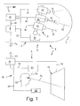
- FIG. 1 shows a preferred embodiment of a device 1 for guiding an unmanned, Aircraft 2 shown only partially in FIG. 1 schematically in a side view shown.
- the new viewing direction (in 1 not shown) via the light beam guide 50 through the line of sight detection device 20 determined and via the signal line 44, the two units 7, 10 and with the help of Signal line 35 transmitted to the swivel mechanism 34, which thereupon the optical Axis 33 of the camera arrangement 5 in accordance with the new viewing direction of the ground pilot established.
- the new flight vision area is then, as explained above, in an analogous manner on the Display device 12 is displayed so that the ground pilot 22 is able to at the ground station 11 is to monitor the field of vision of the unmanned aerial vehicle 2 flying in the airspace.
Abstract
Description
Die Erfindung bezieht sich auf ein Verfahren zum Führen eines unbemannten Fluggerätes nach
dem Oberbegriff des Patentanspruchs 1 sowie auf eine Vorrichtung zum Führen eines unbemannten
Fluggerätes nach dem Oberbegriff des Patentanspruchs 9.The invention relates to a method for guiding an unmanned aerial vehicle according to
the preamble of
Unbemannte Fluggeräte können nach den geltenden Luftverkehrsvorschriften dann am allgemeinen Luftverkehr gemäss den einzuhaltenden Sichtflugregeln teilnehmen, wenn ein verantwortlicher Bodenpilot vorhanden ist, der über dieselben Sichtinformationen verfügt, welche ein Pilot an Bord des Fluggerätes beim Blick aus dem Cockpit hätte, um den das Fluggerät umgebenden Flugverkehr zu beobachten und erforderlichenfalls Ausweichmanöver gemäss der Grundregel "See-and-Avoid" zur Kollisionsvermeidung fliegen zu können.Unmanned aerial vehicles can then generally in accordance with the applicable air traffic regulations Participate in air traffic according to the visual flight rules to be observed if a responsible There is a ground pilot who has the same visual information as a Pilot on board the aircraft when looking out of the cockpit would have around the aircraft To observe air traffic and, if necessary, evasive maneuvers in accordance with the Basic rule "See-and-Avoid" to avoid collisions.
Aus der Praxis ist bekannt, auf der Grundlage der Fernsehtechnik, insbesondere der Videotechnik, Bewegtbilder des Flugsichtbereichs an Bord eines unbemannten Fluggerätes aufzunehmen, die aufgenommenen Bewegtbilder an eine Bodenstation zu übertragen und einem Bodenpiloten die übertragenen Bewegtbilder auf einem elektronischen Bildschirm anzuzeigen.It is known from practice, on the basis of television technology, in particular video technology, Record moving images of the flight visibility area on board an unmanned aerial vehicle, to transmit the recorded moving images to a ground station and a ground pilot display the transmitted moving images on an electronic screen.
Die geringe Objektauflösung solcher Videobilder nach dem Stand der Technik, zum Beispiel gemäss der CCIR/PAL-Norm, genügt bei der üblichen weitwinkligen Beobachtung des Flugsichtbereiches jedoch nicht den Anforderungen für die Entdeckung entfernter Objekte, wie beispielsweise auf potentiellem Kollisionskurs befindlichen anderen Fluggeräten. The low object resolution of such prior art video images, for example according to the CCIR / PAL standard, is sufficient for the usual wide-angle observation of the field of vision but not the requirements for the detection of distant objects, such as For example, other aircraft on a potential collision course.
Die Objektauflösung solcher Videobilder nach dem Stand der Technik könnte beispielsweise durch Verwendung von Teleobjektiven erhöht werden. Dabei geht allerdings der mit der in Kauf zu nehmenden Einengung des Gesichtsfeldes verbundene Gesamtüberblick verloren. Um den Gesamtüberblick zurückzugewinnen, hätte der Bodenpilot in regelmässigen Abständen durch Bewegung der Blickrichtung der Teleoptik den vorausliegenden Luftraum abzuscannen. Der Bodenpilot wäre hinsichtlich seiner Wahrnehmungs- und Bildverarbeitungsleistung jedoch nach kurzer Zeit mental überfordert, so dass basierend auf diesem Vorschlag ein Führen eines unbemannten Fluggerätes nach Sichtflugregeln nicht möglich ist.The object resolution of such video images according to the prior art could, for example can be increased by using telephoto lenses. However, the one with the in Purchase-related narrowing of the visual field related overall overview is lost. Around The ground pilot would have to regain the overall view at regular intervals scan the airspace ahead by moving the viewing direction of the telescope. However, the ground pilot would be perceptual and image processing after a short time mentally overwhelmed, so that based on this suggestion, a unmanned aerial vehicle according to visual flight rules is not possible.
Grundsätzlich scheint die Verwendung einer Videobildtechnik mit vielfach gesteigerter Pixelauflösung gegenüber der Standard-Videotechnik ebenfalls für die Darstellung relalistischer Flugsichtszenen geeignet zu sein. Eine solche Videobildtechnik ist bislang allerdings nicht Stand der Technik. Falls eine solche Videobildtechnik in Zukunft verfügbar ist, wäre der Frequenz-Bandbreitenbedarf der Funk-Bildübertragung gegenüber demjenigen des Standes der Technik vielfach gesteigert, so dass die für die Funkübertragung aus unbemannten Fluggeräten verfügbaren Kanalkapazitäten überschritten wären.Basically, the use of video imaging technology with a much increased pixel resolution seems compared to the standard video technology also for the representation more relalistic Flight view scenes to be suitable. So far, however, such video imaging technology has not been used State of the art. If such video imaging technology is available in the future, it would be Frequency bandwidth requirement of radio image transmission compared to that of the prior art Technology increased many times over, so that for radio transmission from unmanned aerial vehicles available channel capacities would be exceeded.
Bislang ist es daher nicht möglich, unbemannte Fluggeräte im unkontrollierten Luftraum nach den geltenden Sichtflugregeln fliegen zu können. Der kontrollierte Luftraum, welcher üblicherweise oberhalb des unkontrollierten Luftraums liegt, ist für unbemannte Fluggeräte relativ hoch und daher für den Einsatz solcher Geräte wenig interessant.So far, it has not been possible to trace unmanned aerial vehicles in uncontrolled airspace to be able to fly the applicable visual flight rules. The controlled airspace, which is usually above uncontrolled airspace is relatively high for unmanned aerial vehicles and therefore of little interest for the use of such devices.
Der Erfindung liegt daher die Aufgabe zugrunde, ein Verfahren der eingangs angegebenen Art zu schaffen, gemäss dem ein unbemanntes Fluggerät nach den geltenden Sichtflugregeln fliegen kann. Der Erfindung liegt ferner die Aufgabe zugrunde, eine Vorrichtung der eingangs erwähnten Art zu schaffen, mit dem ein Führen des unbemannten Fluggerätes nach den geltenden Sichtflugregeln möglich ist.The invention is therefore based on the object of a method of the type specified to create, according to which an unmanned aerial vehicle can fly according to the applicable visual flight rules can. The invention is also based on the object of a device of the type mentioned To create a way to guide the unmanned aerial vehicle in accordance with the applicable Visual flight rules is possible.
Diese Aufgabe wird erfindungsgemäss durch ein Verfahren mit den Merkmalen des Patentanspruchs
1 sowie durch eine Vorrichtung mit den Merkmalen des Patentanspruchs 9 gelöst.According to the invention, this object is achieved by a method having the features of the
Vorteilhafte Weiterbildungen sind Gegenstand der jeweiligen Unteransprüche.Advantageous further developments are the subject of the respective subclaims.
Durch das Aufnehmen der Bewegtbilder mit oder aus mindestens zwei unterschiedlichen Bildaufnahmewinkeln, das Überlagern dieser Bewegtbilder und das Aufnehmen der Bewegtbilder entsprechen der Blickrichtung eines beispielsweise an einer Bodenstation befindlichen Bodenpiloten, kann diesem einerseits ein weitgehend realitätsgetreues Bild des Flugsichtbereichs angezeigt werden; andererseits erfolgt das Aufnehmen der Bewegtbilder in Abhängigkeit von der Blickrichtung des Bodenpiloten, so dass dieser die Blickrichtung und damit den aufzunehmenden Teil des Flugsichtbereiches selbst bestimmt und festlegt. Bei Feststellung anderer potentiell auf Kollisionskurs befindlicher Fluggeräte kann der Bodenpilot dann entsprechende Ausweichmannöver durchführen. Vorteilhaft ist dabei, dass das erfindungsgemässe Verfahren unter Nutzung von Komponenten der Standardvideotechnik und mittels üblichen Funkübertragungskomponenten auf Grund von Kanalkapazitäten entsprechend Standardvideokanälen durchgeführt werden kann. Damit ist ein Führen eines unbemannten Fluggeräts nach Sichtflugregeln auf relativ einfache Weise möglich. Solche Fluggeräte könnten damit beispielsweise auch im unkontrollierten Luftraum eingesetzt werden.By taking the moving pictures with or from at least two different ones Image capturing angles, superimposing these moving images and capturing the moving images correspond to the direction of view of one located at a ground station, for example Ground pilots, this can give a largely realistic picture of the flight vision area are displayed; on the other hand, the moving images are taken in dependence from the direction of view of the ground pilot, so that the direction of view and thus the determine and determine the part of the flight vision area to be recorded. If found The ground pilot can then use other aircraft that are potentially on a collision course Perform evasive maneuvers. It is advantageous that the inventive Process using components of standard video technology and using conventional Radio transmission components based on channel capacities corresponding to standard video channels can be carried out. This is a tracking of an unmanned aerial vehicle Visual flight rules possible in a relatively simple way. Such aircraft could, for example can also be used in uncontrolled airspace.
Vorteilhafterweise überlagern schmalwinklige Bewegtbilder jeweils weitwinkligere Bewegtbilder, wobei die Bewegtbilder vorzugsweise in konzentrischer oder nahezu konzentrischer Weise überlagert angezeigt werden. Damit sind die angezeigten Bewegtbilder jeweils aus mindestens zwei Bildern zusammengesetzt, die aus unterschiedlichen Bildaufnahmewinkeln aufgenommen worden sind. Dadurch erhält der Bodenpilot eine Anzeige des Flugsichtbereichs, welche aus einem zwar eingeengteren, aber dafür mit einer höheren Bildauflösung versehenen Bildbereich und einem weitwinkligeren Bildbereich mit allerdings verringerter Bildauflösung kombiniert ist. Eine solche Anzeige ist zumindest ein Stück weit an die menschliche Sehauflösung bzw. Sehschärfe angepasst.Advantageously, narrow-angle moving images superimpose wide-angle moving images, the moving images preferably in a concentric or almost concentric manner overlaid. This means that the displayed moving images are each at least put together two images taken from different image acquisition angles have been. This gives the ground pilot an indication of the flight visibility area, which consists of a although narrower, but with a higher image resolution and a wide-angle image area is combined with, however, reduced image resolution. Such a display is at least a bit closer to the human visual resolution or Visual acuity adjusted.
Gemäss einer Weiterbildung der Erfindung liegt der gemeinsame Bildmittelpunkt der überlagerten Bewegtbilder genau in Blickrichtung des Bodenpiloten. Dadurch erhält der Bodenpilot den Eindruck, er selbst sitze im Cockpit des Fluggeräts und überwache den Flugsichtbereich, d.h. den vorausliegenden Luftraum, des Fluggeräts, was die realitätsgetreue Anzeige und Wahrnehmung durch den Bodenpiloten weiter verbessert.According to a development of the invention, the common center of the image is the superimposed one Moving images exactly in the line of sight of the ground pilot. This gives the ground pilot the Impression that he himself is sitting in the cockpit of the aircraft and monitors the flight vision area, i.e. the airspace ahead, the aircraft, what the realistic display and perception further improved by the ground pilot.
Gemäss einer anderen Weiterbildung werden die Bewegtbilder nicht mit scharfen Rändern sondern mit vorzugsweise stetig zum Bildrand zunehmender Transparenz überlagert. Diese Weiterbildung hat den Vorteil, dass dem Betrachter, beispielsweise also dem Bodenpiloten, der Umstand der Bildüberdeckung bzw. -überlagerung nicht auffällt und so ein noch realistischerer Bildeindruck entsteht.According to another development, the moving images are not with sharp edges but superimposed with transparency that increases continuously towards the edge of the image. This training has the advantage that the viewer, for example the ground pilot, the circumstance the image overlap or overlay is not noticeable and so an even more realistic Picture impression arises.
Gemäss einer vorteilhaften Weiterbildung der Erfindung werden die schmalwinkligsten Bewegtbilder als vergrösserte Bewegtbilder gewonnen. Auf diese Weise ist es möglich, die "Entdeckungsreichweite" für potentiell auf Kollisionskurs befindliche Fluggeräte zu steigern. According to an advantageous development of the invention, the narrowest-angle moving images obtained as enlarged moving pictures. In this way it is possible to Increase "detection range" for aircraft potentially on a collision course.
Gemäss einer besonders bevorzugten Ausführungsform der Erfindung erfolgt das Aufnehmen der Bewegtbilder mit Bildaufnahmewinkeln und diesen jeweils zugeordneten Bildauflösungen, die an diejenigen der etwa symmetrischen Sehschärfekurve des menschlichen Auges angepasst sind. Damit kann der Bodenpilot ein Bild sehen, das der realen Flugsicht in seiner momentanen Blickrichtung entspricht und gleichzeitig seiner Sehauflösung angepasst ist. Die Sehschärfe des menschlichen Auges besitzt nämlich im Zentralbereich, d.h. nahe der optischen Achse, ein scharfes, d.h. deutlich ausgeprägtes, Maximum, welches etwa einer Bogenminute Winkelauflösung entspricht. Mit zunehmener Winkelablage aus der optischen Achse nimmt die Sehschärfe des menschlichen Auges stark ab. Erfindungsgemäss können also die aufgenommenen Bewegtbilder derart überlagert werden, dass das schmalwinkligst aufgenommene Bewegtbild und das weitwinkligst aufgenommene Bewegtbild in ihren Bildwinkeln und ihrer Bildauflösung derart miteinander kombiniert sind, dass das zur Anzeige gebrachte Bewegtbild hinsichtlich des Bildwinkels und der Bildauflösung der zentralen Sehauflösung des menschlichen Auges entspricht. Dadurch wird die realitätsgetreue Abbildung und Anzeige des Flugsichtbereiches weiter verbessert.According to a particularly preferred embodiment of the invention, the recording takes place the moving images with image recording angles and the image resolutions assigned to them, adapted to those of the approximately symmetrical visual acuity curve of the human eye are. This enables the ground pilot to see an image that shows the current flight view in its current state Direction of view corresponds and at the same time is adapted to its visual resolution. The visual acuity of the namely, in the central area, i.e. near the optical axis sharp, i.e. clearly pronounced, maximum, which is about an arc minute angular resolution equivalent. As the angular offset from the optical axis increases, the visual acuity decreases of the human eye. According to the invention, the recorded moving images can are superimposed in such a way that the moving picture and the widest-angle moving picture in its picture angles and their picture resolution are combined with one another in such a way that the moving image which is displayed with respect to the Angle of view and the image resolution of the central visual resolution of the human eye corresponds. As a result, the realistic mapping and display of the flight vision area is expanded improved.
Gemäss einer anderen Weiterbildung der Erfindung wird in den aufgenommenen Bewegtbildem mit Hilfe von Bildverarbeitungstechniken automatisch nach anderen Fluggeräten gesucht, wobei vorzugsweise der gesamte Flugsichtbereich systematisch im sequentiellen Takt abgescannt und ausgewertet wird, und gegebenenfalls erforderliche Ausweichmanöver vorzugsweise automatisch durchgeführt werden. Mit einer solchen Automatik wird allerdings das Prinzip der menschlichen Verantwortung für die eingangs erwähnte "See-and-Avoid"-Sichtflugführung des unbemannten Fluggerätes aufgegeben und eine hinsichtlich der Luftverkehrsvorschriften bisher noch nicht geregelte Situation erreicht. Es wird darauf hingewiesen, dass bei dieser Weiterbildung ein Aufnehmen der Bewegtbilder entsprechend der Blickrichtung eines Bodenpiloten entfallen kann.According to another development of the invention, the recorded moving images automatically searched for other aircraft using image processing techniques, preferably the entire area of flight vision is scanned systematically in a sequential cycle and is evaluated, and preferably necessary evasive action be carried out automatically. With such an automatic, however, the principle of human responsibility for the "See and Avoid" visual flight guidance of the abandoned unmanned aerial vehicle and one so far in terms of air traffic regulations situation not yet reached. It should be noted that this training recording the moving images according to the direction of view of a ground pilot can be omitted.
Vorrichtungsseitig ist die Kameraanordnung derart angeordnet und ausgebildet, dass die Bewegtbilder damit aus mindestens zwei unterschiedlichen Bildaufnahmewinkeln aufgenommen werden, wobei eine Mischeinrichtung zur passenden Überlagerung der aufgenommenen Bilder, eine Blickrichtungs-Erfassungseinrichtung, mit der die Blickrichtung eines Bodenpiloten erfassbar und das Aufnehmen zumindest eines Teils der Bewegtbilder entsprechend der Blickrichtung beeinflussbar ist, und eine Einrichtung zum Fernsteuern des Fluggerätes vorgesehen sind. Damit kann die Kameraanordnung mit gestuften Bildaufnahmewinkeln, beispielsweise von "Weitwinkel" bis "Tele", arbeiten. Die Übertragung der Videobildsignale der Kameraanordnung zum Arbeitsplatz eines Bodenpiloten, beispielsweise zu einer Bodenstation, erfolgt vorteilhafterweise per Funk.On the device side, the camera arrangement is arranged and designed such that the Moving images are thus recorded from at least two different image recording angles be, with a mixing device for appropriate superimposition of the recorded Images, a line of sight detection device with which the direction of view of a ground pilot detectable and the recording of at least some of the moving images according to the viewing direction can be influenced, and a device for remote control of the aircraft is provided are. This allows the camera arrangement with stepped image recording angles, for example from "wide angle" to "tele". The transmission of the video image signals of the camera arrangement to the workplace of a ground pilot, for example to a ground station advantageously by radio.
Gemäss einer Ausführungsform der Erfindung weist die Kameraanordnung eine elektronische Bewegtbildkamera, vorzugsweise eine Videokamera, auf, mittels der durch schnellen sequentiellen Wechsel von Tele- und Weitwinkelobjektiven ein sequentieller Datenstrom der Teleund Weitwinkelbewegtbilder erzeugbar ist. Dieser Datenstrom kann nach Funkübertragung an der Bodenstation in die zugrundeliegenden Einzelbilder aufgeteilt werden. Bei dieser Kameraanordnung ist also lediglich eine einzige Bewegtbildkamera erforderlich, welche am Fluggerät installiert ist.According to one embodiment of the invention, the camera arrangement has an electronic one Moving image camera, preferably a video camera, on by means of fast sequential Change of telephoto and wide-angle lenses a sequential data stream of the Teleund Wide-angle moving images can be generated. This data stream can be sent after radio transmission the ground station can be divided into the underlying individual images. With this camera arrangement all that is required is a single moving image camera, which is attached to the aircraft is installed.
Gemäss einer bevorzugten Ausführungsform der Erfindung weist die Kameraanordnung wenigstens zwei elektronische Bewegtbildkameras, vorzugsweise Videokameras, mit gestuften Bildaufnahmewinkeln vorzugsweise von "Tele" bis "Weitwinkel" auf, wobei vorzugsweise die optischen Achsen der wenigstens zwei Bewegtbildkameras raumparallel zueinander ausgerichtet sind. Die eine Bewegtbildkamera kann somit eine Videokamera mit Teleobjektiv, die andere eine solche mit Weitwinkelobjektiv sein, so dass der zuvor hinsichtlich lediglich einer Bewegtbildkamera angegebene schnelle sequentielle Wechsel von Tele- und Weitwinkelobjektiv bei dieser Ausführungsform nicht erforderlich ist. Dadurch ist die Reparaturanfälligkeit der verwendeten Kameras reduziert, die Betriebskosten der gesamten Vorrichtung sind dadurch verringert.According to a preferred embodiment of the invention, the camera arrangement has at least two electronic moving image cameras, preferably video cameras, with stepped image recording angles preferably from "telephoto" to "wide angle", preferably the optical ones Axes of the at least two moving image cameras aligned parallel to each other are. One moving image camera can thus be a video camera with a telephoto lens, the other be one with a wide-angle lens, so that previously with regard to only one moving-image camera specified rapid sequential change of telephoto and wide-angle lens at this embodiment is not required. This makes the used repairs vulnerable Cameras reduced, the operating costs of the entire device are reduced reduced.
Gemäss einer vorteilhaften Weiterbildung der Erfindung ist wenigstens eine Kamera der Kameraanordnung um zwei Raumachsen, vorzugsweise die Nickachse und die Gierachse, ferngesteuert schwenkbar am Fluggerät angeordnet, wobei es gemäss einer Weiterbildung der Erfindung möglich ist, die weitwinkligste Bewegtbildkamera ortsfest am Fluggerät zu installieren. Bei der letztgenannten Ausführungsform ist also lediglich die schmalwinkligste Bewegtbildkamera schwenkbar am Gerät installiert. Der Weitwinkel der weitwinkligsten Bewegtbildkamera kann derart gewählt sein, dass damit nahezu der gesamte Flugsichtbereich abgedeckt ist. Die weitwinkligste Bewegtbildkamera kann damit ein Übersichtsbild des gesamten Flugsichtbereiches liefern, allerdings, wie zuvor erwähnt, mit geringerer Pixelauflösung. Es ist aber auch möglich, die gesamte Kameraanordnung mit ihren sämtlichen Kameras schwenkbar am Fluggerät zu installieren.According to an advantageous development of the invention, at least one camera of the camera arrangement remotely controlled around two spatial axes, preferably the pitch axis and the yaw axis arranged pivotally on the aircraft, it being according to a development of the invention it is possible to install the widest-angled moving-image camera stationary on the aircraft. In the last-mentioned embodiment, therefore, only the narrowest-angle moving image camera is pivotally installed on the device. The wide angle of the most wide-angle motion picture camera can be selected in such a way that almost the entire flight viewing area is covered. The The widest-angle moving image camera can thus provide an overview image of the entire flight vision area deliver, however, as mentioned before, with lower pixel resolution. It is also possible to swivel the entire camera arrangement with all its cameras on the aircraft to install.
Vorteilhafterweise sind die mittels der Kameraanordnung aufgenommenen Bewegtbilder jeweils konzentrisch oder nahezu konzentrisch überlagert anzeigbar, wobei vorzugsweise der gemeinsame Mittelpunkt der überlagerten Bewegtbilder genau in Blickrichtung des Bodenpiloten angeordnet ist. Dadurch wird vorrichtungsseitig die, wie zuvor in bezug auf das erfindungsgemässe Verfahren erwähnte, weitgehend realitätsgetreue Abbildung des Flugsichtbereiches unterstützt und ermöglicht.The moving images recorded by means of the camera arrangement are advantageous each can be displayed concentrically or almost concentrically superimposed, preferably the common center of the superimposed moving images exactly in the direction of the ground pilot is arranged. As a result, on the device side, this is the same as previously with regard to the inventive The method mentioned, largely realistic representation of the flight vision area supports and enables.
Gemäss einer anderen Weiterbildung der Erfindung ist die Überlagerung der angezeigten Bewegtbilder durch Komponenten der Bildverarbeitung derart gestaltet, dass die Bewegtbilder nicht mit scharfen Rändern sondern mit vorzugsweise stetig zum Bildrand zunehmender Transparenz versehen sind. Dadurch entsteht an der Anzeigeeinrichtung ein noch realitätsgetreueres Bild des aufgenommenen Flugsichtbereiches.According to another development of the invention, the superimposition of the displayed moving images is designed by components of the image processing in such a way that the moving images not with sharp edges, but with transparency that increases steadily towards the edge of the image are provided. This creates an even more realistic one on the display device Image of the recorded flight visibility area.
Gemäss einer besonders bevorzugten Ausführungsform der Erfindung ist die schmalwinkligste Bewegtbildkamera, vorzugsweise jede Bewegtbildkamera, bezüglich ihres Bildaufnahmewinkels und ihrer diesem zugeordneten Bildauflösung so dimensioniert, dass die resultierenden Pixelauflösungen der jeweiligen Bewegtbildkamera an die etwa symmetrische Sehschärfekurve des menschlichen Auges angepasst sind. Dadurch ist die Möglichkeit geschaffen, dass der Bodenpilot an der Anzeigeeinrichtung ein Bild sieht, das seiner Sehschärfekurve angepasst ist, wodurch eine weitgehend realitätsgetreue Abbildung des Flugsichtbereiches gewährleistet sein kann.According to a particularly preferred embodiment of the invention, the narrowest is Moving image camera, preferably each moving image camera, with regard to its image recording angle and its associated image resolution dimensioned so that the resulting Pixel resolutions of the respective moving image camera on the approximately symmetrical visual acuity curve of the human eye. This creates the possibility that the Ground pilot sees an image on the display device that is adapted to his visual acuity curve, whereby a largely realistic representation of the flight vision area can be guaranteed can.
Gemäss einer vorteilhaften Weiterbildung der Erfindung erfasst die Blickrichtungs-Erfassungseinheit sowohl die Kopfstellung als auch die Augenbewegung des Bordpiloten, wobei die Kameraanordnung dementsprechend steuerbar ist. Es ist klar, dass die Blickrichtung der bordseitigen Kameraanordnung bei dieser Ausführungsform stets genau und vor allem ohne merklichen Zeitverlust der Blickrichtung des Piloten folgt. Damit kann der Bodenpilot selbst bestimmen, an welcher Stelle der Flugsichtbereich erfasst und überwacht werden soll. Die Blickrichtungs-Erfassungseinrichtung kann beispielsweise ein am oder nahe dem Kopf des Bodenpiloten installierter Blickrichtungs-Erfassungssensor, beispielsweise eine Blickbewegungskamera, sein.According to an advantageous development of the invention, the viewing direction detection unit detects both the head position and the eye movement of the pilot on board, the Camera arrangement can be controlled accordingly. It is clear that the viewing direction of the on-board camera arrangement in this embodiment always accurate and above all without noticeable loss of time follows the pilot's line of sight. The ground pilot can do this himself determine at which point the flight vision area should be recorded and monitored. The Viewing direction detection device can, for example, be at or near the head of the Ground pilots installed gaze direction detection sensor, for example a gaze motion camera, his.
Ausführungsbeispiele des Erfindungsgegenstandes werden nachfolgend an Hand der Zeichnung näher erläutert, wobei alle beschriebenen und/oder bildlich dargestellten Merkmale für sich oder in beliebiger Kombination den Gegenstand der vorliegenden Erfindung unabhängig von ihrer Zusammenfassung in den Ansprüchen oder deren Rückbeziehung bilden. Es zeigen:
- Fig. 1
- eine schematische Darstellung einer Vorrichtung zum Führen eines unbemannten Fluggerätes; und
- Fig. 2
- eine schematische Darstellung einer Überlagerung konzentrischer Teilbilder gemäss der Sehschärfekurve des menschlichen Auges.
- Fig. 1
- a schematic representation of a device for guiding an unmanned aerial vehicle; and
- Fig. 2
- is a schematic representation of a superposition of concentric partial images according to the visual acuity curve of the human eye.
In Fig. 1 ist eine bevorzugte Ausführungsform einer Vorrichtung 1 zum Führen eines unbemannten,
in Fig. 1 lediglich teilweise dargestellten Fluggerätes 2 schematisch in einer Seitenansicht
dargestellt.1 shows a preferred embodiment of a
Die Vorrichtung 1 hat einen bordseitigen, in Fig. 1 oben dargestellten Teil 3 sowie einen bodenseitigen,
in Fig. 1 unten dargestellten Teil 4. Die Vorrichtung 1 hat in ihrem bordseitigen Teil 3
eine Kameraanordnung 5 zum Aufnehmen von Bewegtbildern des Flugsichtbereiches 6, d.h.
des vorausliegenden Luftraumes, welcher sich in Fig. 1 rechts vom Fluggerät befindet. Demnach
bewegt sich das Fluggerät 2 beispielsweise in Richtung parallel zum Pfeil A. Die Vorrichtung
1 hat in ihrem bordseitigen Teil 3 ferner eine Sender-Empfänger-Einheit 7 und in ihrem
bodenseitigen Teil 4 eine Empfänger-Sender-Einheit 10 zum Übertragen der aufgenommenen
Bewegtbilder an eine Bodenstation 11, welche insbesondere den bodenseitigen Teil 4 der
Vorrichtung 1 umfasst. Ausserdem hat die Vorrichtung 1 eine Einrichtung 12 zum Anzeigen
der übertragenen Bewegtbilder, welche zum bodenseitigen Teil 4 der Vorrichtung 1, d.h.
insbesondere zur Bodenstation 11, gehört. Die Anzeigeeinrichtung 12 ist beispielsweise ein
Bilddarstellungsgerät, insbesondere ein Computermonitor, welches Bildauflösungen besitzt, die
wesentlich über der Standard-Videoauflösung liegen und bei geeignetem Betrachtungsabstand
der menschlichen Sehauflösung entsprechen.The
Erfindungsgemäss ist die Kameraanordnung 5 derart angeordnet und ausgebildet, dass die Bewegtbilder
damit aus mindestens zwei unterschiedlichen Bildaufnahmewinkeln aufgenommen
werden. Die Vorrichtung umfasst ferner eine Mischeinrichtung 13 zur passenden Überlagerung
der aufgenommenen Bilder, wobei die Mischeinrichtung 13 über Bildsignalleitungen 14, 15, 16
mit der Kameraanordnung 5 verbunden ist. Die Mischeinrichtung 13 wiederum ist über eine
Leitung 17 mit der Sender-Empfänger-Einheit 7 verbunden, durch welche das kombinierte Bildsignal
von letzterer Einheit übertragen wird.According to the invention, the
An ihrem bodenseitigen Teil 4 hat die Vorrichtung 1 ausserdem eine Blickrichtungs-Erfassungseinrichtung
20, mit der die Blickrichtung 21 eines schematisch lediglich angedeuteten
Bodenpiloten 22 auf die Anzeigeeinrichtung 12 erfassbar und das Aufnehmen zumindest eines
Teils der Bewegtbilder entsprechend dieser Blickrichtung des Bodenpiloten beeinflussbar ist.
Schliesslich hat die Vorrichtung an ihrer Bodenstation 11 ferner eine Einrichtung 23 zum
Fernsteuern des Fluggerätes 2, welche über eine Signalleitung 24 mit der Empfänger-Sender-Einheit
10 verbunden ist oder auch so ausgebildet sein kann, dass sie entsprechende Fernsteuersignale
direkt an das Fluggerät 2 überträgt.On its bottom part 4, the
Gemäss einer ersten, nicht näher gezeigten Ausführungsform der Erfindung weist die Kameraanordnung
5 lediglich eine elektronische Bewegtbildkamera, vorzugsweise eine Videokamera
auf, mit der durch schnellen sequentiellen Wechsel von Tele- und Weitwinkelobjektiven ein
sequentieller Datenstrom der Tele- und Weitwinkelbewegtbilder erzeugbar und zur Mischeinrichtung
13 übertragbar ist.According to a first, not shown embodiment of the invention, the
Gemäss einer anderen Ausführungsform der Erfindung weist die Kameraanordnung 5 wenigstens
zwei, gemäss der in Fig. 1 dargestellten Ausführungsform drei elektronische Bewegtbildkameras
25, 26, 27 auf, die vorzugsweise als Videokameras ausgestaltet sind und mit gestuften
Bildaulhahmewinkeln vorzugsweise von "Tele" bis "Weitwinkel" ausgestattet sind. So ist die in
Fig. 1 obere Bewegtbildkamera 25 beispielsweise eine Weitwinkelkamera, die mittlere
Bewegtbildkamera 26 eine Kamera mit Normalobjektiv und die untere Bewegtbildkamera 27
eine Kamera mit Teleobjektiv. Dementsprechend verringern sich die Bildaufnahmewinkel 30,
31, 32 in Fig. 1 von oben nach unten. Die optischen Achsen, von denen in Fig. 1 der besseren
Übersicht halber lediglich die optische Achse 33 der mittleren Bewegtbildkamera 26 gezeigt ist,
sind raumparallel zueinander ausgerichtet.According to another embodiment of the invention, the
Für ein Videosystem gemäss dem PAL-Standard mit einer Pixelauflösung von 768 Pixel in
horizontaler Richtung x 576 Pixel in vertikaler Richtung folgt daraus ein Bildfeld für die
schmalwinkligste Kamera, das ist gemäss Fig. 1 die untere Bewegtbildkamera 27, von maximal
etwa 12° x 9°.For a video system according to the PAL standard with a pixel resolution of 768 pixels in
horizontal direction x 576 pixels in the vertical direction, this results in an image field for the
The narrowest-angle camera, that is the lower moving-
Wenigstens eine Kamera, nämlich diejenige Bewegtbildkamera mit dem schmalwinkligsten
Bildaufnahmewinkel, d.h. im Falle der Fig. 1 die Bewegtbildkamera 27, der Kameranordnung 5
ist um zwei Raumachsen, vorzugsweise die Nickachse und die Gierachse, mittels eines
Schwenkmechanismus 34 ferngesteuert schwenkbar am Fluggerät 2 angeordnet. Gemäss der in
Fig. 1 gezeigten Ausführungsform sind sämtliche Kameras 25 - 27 der Kameraanordnung 5 um
die genannten Achsen schwenkbar, wobei eine Schwenkbewegung um die Nickachse ein
Verschwenken der Kameraanordnung nach oben bzw. unten und ein Verschwenken der Anordnung
um die sogenannte Gierachse ein Schwenken der Kameraanordnung nach rechts bzw.
links ermöglicht. Es ist klar, dass auch der Schwenkmechanismus 34 über eine Signalleitung 35
mit der Sender-Empfänger-Einheit 7 gekoppelt ist. At least one camera, namely the moving picture camera with the narrowest angle
Image acquisition angle, i.e. in the case of FIG. 1, the moving-
Gemäss einer anderen, nicht gezeigten Ausführungsform der Erfindung ist es auch möglich, die
weitwinkligste Bewegtbildkamera, das ist im Falle der Ausführungsform der Fig. 1 die Bewegtbildkamera
25, ortsfest am Fluggerät 2 zu installieren und lediglich die schmalwinkligste Bewegtbildkamera
oder gemäss der Ausführungsform in Fig. 1 die Bewegtbildkameras 26 und 27
schwenkbar am Fluggerät zu befestigen.According to another embodiment of the invention, not shown, it is also possible to
widest-angle moving image camera, that is the moving image camera in the case of the embodiment of FIG. 1
25, to be installed stationary on
Erfindungsgemäss sind die mittels der Kameraanordnung 5 aufgenommenen Bewegtbilder vorzugsweise
mittels der Mischeinrichtung 13 jeweils konzentrisch oder nahezu konzentrisch überlagert
an der Anzeigeeinrichtung 12 anzeigbar, wobei vorzugsweise der gemeinsame Mittelpunkt
der überlagerten Bewegtbilder genau in Blickrichtung 21 des Bodenpiloten angeordnet
ist. Die erwähnte Anzeigeeinrichtung ist beispielsweise ein Projektionsschirm oder eine nicht
näher gezeigte Monitorbrille für den Bodenpiloten. Bei den angezeigten Bildern überdecken
jeweils schmalwinklige Bewegtbilder weitwinkligere Bewegtbilder. Wie erwähnt, erfolgt die
Überlagerung der Bewegtbilder vorzugsweise durch die Mischeinrichtung 13 im bordseitigen
Teil 3 der Vorrichtung 1. Es ist aber auch möglich, die Mischeinrichtung 13 im bodenseitigen
Teil 4 der Vorrichtung 1 auszubilden und die von der Kameranordnung übertragenen Signale
erst am Boden zu einem gemeinsamen Bewegtbild zusammenzubringen. Gemäss einer bevorzugten,
nicht näher gezeigten Ausführungsform der Erfindung ist die Überlagerung der angezeigten
Bewegtbilder durch Komponenten der Bildverarbeitung derart gestaltet, dass die
Bewegtbilder nicht mit scharfen Rändern sondern mit vorzugsweise stetig zum Bildrand zunehmender
Transparenz versehen sind.According to the invention, the moving images recorded by the
Die Kameraanordnung 5 kann ferner gemäss einer Weiterbildung der Erfindung derart ausgebildet
sein, dass das schmalwinkligste Bewegtbild, d.h. das dem Teleobjektiv mit der grössten
Brennweite entsprechende Bild, durch Wahl einer längeren Brennweite als vergrössertes Bild
entsprechend dem Blick durch ein Fernglas gewonnen wird.The
Gemäss einer besonders bevorzugten Ausführungsform der Erfindujng ist die schmalwinkligste
Bewegtbildkamera 27, vorzugsweise jedoch jede Bewegtbildkamera 25 - 27, bezüglich ihres
Bildaufnahmewinkels und ihrer diesem zugeordneten Bildauflösung so dimensioniert, dass die
resultierenden Pixelauflösungen der jeweiligen Bewegtbildkamera an die etwa symmetrische
Sehschärfekurve 36 des menschlichen Auges angepasst ist. Eine solche Sehschärfekurve ist
schematisch in gestrichelten Linien in Fig. 2 gezeigt.According to a particularly preferred embodiment of the invention, the narrowest angle is
Moving
In Fig. 2 ist die Sehauflösung bzw. Sehschärfe in Abhängigkeit der Winkelablage 40 von der
optischen Achse 37 dargestellt, wobei die Winkelablage 40 von der optischen Achse 37 in den
beiden Richtungen B und C zunimmt. Die Sehschärfekurve 36 zeigt also die Pixelauflösung des
menschlichen Auges in Abhängigkeit von der Winkelablage aus der optischen Achse 37. Fig. 2
verdeutlicht, dass die Sehschärfekurve 36 des menschlichen Auges ein scharfes, d.h. deutlich
ausgeprägtes Maximum der Sehauflösung im Bereich kleiner Winkelablagen 40 aus der optischen
Achse 37 hat. Mit zunehmender Winkelablage 40 fällt die Sehschärfekurve 36 dann deutlich
ab. Die Auflösungen 41 - 43 der mit den Bewegtbildkameras 25 - 27 der Kameraanordnung
5 aufgenommenen Bilder sind in bezug auf jede der genannten Kameras in Fig. 2 angegeben
und in der Weise der Sehschärfekurve 36 des menschlichen Auges angepasst, dass die resultierenden
Pixelauflösungen etwa den Verlauf der Sehschärfekurve nachbilden und damit zu
diesem passen.2, the visual resolution or visual acuity is dependent on the angular offset 40
Die in Fig. 2 gezeigte Auflösung 41 entspricht derjenigen der Bewegtbildkamera 25 (Weitwinkelkamera),
die Pixelauflösung 42 derjenigen der Bewegtbildkamera 26 (Normalwinkelkamera)
und die Pixelauflösung 43 entspricht derjenigen der Bewegtbildkamera 27 (schmalwinkligste
Kamera).The
Die Blickrichtungs-Erfassungseinrichtung 20 erfasst sowohl die Kopfstellung als auch die Augenbewegung
des Bordpiloten, wobei die Kameraanordnung 5 entsprechend der Blickrichtung
des Bodenpiloten steuerbar ist.The direction of
Gemäss einer anderen, nicht gezeigten Ausführungsform der Erfindung ist es möglich, mit Hilfe
von Techniken der Bildverarbeitung in den aufgenommenen Bewegtbildern automatisch nach
anderen Fluggeräten zu suchen. Diese anderen Fluggeräte heben sich in ihrer Bewegung vom
allgemeinen Himmels- und Erdhintergrund ab. Die aufgefundenen Objekte oder Geräte können
gemäss einer Ausgestaltung der Erfindung in der Darstellung der aufgenommenen Bewegtbilder,
d.h. auf der Anzeigeeinrichtung 12, auffällig dargestellt werden. Dies kann beispielsweise
durch eine Einfärbung oder durch Blinken erfolgen. Es ist auch möglich, die voraussichtliche
Flugbahn der aufgefundenen Objekte oder Geräte zu extrapolieren und darzustellen, um die
Beurteilung einer Kollisionsgefahr zu erleichtern.According to another embodiment of the invention, not shown, it is possible to use
techniques of image processing in the recorded moving images automatically
other aircraft to look for. These other aircraft stand out in their movement
general sky and earth background. The objects or devices found can
according to an embodiment of the invention in the representation of the recorded moving images,
i.e. are displayed conspicuously on the
Gemäss einer anderen Ausführungsform der Erfindung ist es möglich, die Suche nach anderen
Fluggeräten automatisch auf den gesamten Flugsichtbereich auszudehnen, indem der gesamte
Flugsichtbereich systematisch beispielsweise im sequentiellen Takt abgescannt und ausgewertet
wird. Auf diese Weise ist eine vollautomatische Entdeckung anderer Fluggeräte möglich, wobei
eine weitere Ausgestaltung der Erfindung mit einer Automatik zum Durchführen von systematisch
erforderlichen Ausweichmanövern ausgestattet sein kann. In den vorerwähnten Fällen
einer automatischen Suche nach anderen Fluggeräten und insbesondere beim vollautomatischen
Entdecken anderer Fluggeräte und bei der vollautomatischen Durchführung von Ausweichmanövern
kann die zuvor erläuterte Blickrichtungs-Erfassungseinrichtung 20 entfallen, da
gemäss dieser Weiterbildung der Erfindung ein Bodenpilot nicht mehr erforderlich ist. Es bleibt
künftigen Luftverkehrsvorschriften vorbehalten, ob mit Hilfe der vollautomatischen erfindungsgemässen
Vorrichtung ein Fliegen von unbemannten Fluggeräten nach Sichtflugregeln gestattet
ist.According to another embodiment of the invention, it is possible to search for others
Aircraft automatically expand to the entire flight viewing area by the entire
The flight vision area is systematically scanned and evaluated, for example in a sequential cycle
becomes. In this way, a fully automatic discovery of other aircraft is possible
a further embodiment of the invention with an automatic system for performing systematically
necessary evasive maneuvers can be equipped. In the aforementioned cases
an automatic search for other aircraft, especially the fully automatic one
Discover other aircraft and perform fully automatic evasive maneuvers
For example, the previously described line of
Es ist klar, dass auch die Blickrichtungs-Erfassungseinrichtung 20 und die Anzeigeeinrichtung
12 über Signalleitungen 44, 45 mit der Empfänger-Sender-Einheit 10 verbunden sind. Ferner
haben sowohl die Sender-Empfänger-Einheit 7 als auch die Empfänger-Sender-Einheit 10 zum
Übertragen der Bildsignale jeweils eine Antenne 46, 47.It is clear that the viewing
Die Blickrichtungs-Erfassungseinrichtung 20 ist beispielsweise eine Blickbewegungskamera,
die mittels einer damit verbundenen Lichtstrahlführung 50 die Blickrichtung 21 des Bodenpiloten
22 ermittelt und als Blickrichtungssignal über die Signalleitung 44 und die Empfänger-Sender-Einheit
10 sowie die Sender-Empfänger-Einheit 7 und die Signalleitung 35 an den
bordseitigen Schwenkmechanismus 34 übertragen wird. Damit ist die bordseitige Kameraanordnung
5 nach den die Blickrichtung des Bodenpiloten betreffenden, funkübermittelten
Angaben schwenk- und steuerbar.The gaze
Nachfolgend wird das erfindungsgemässe Verfahren zum Führen eines unbemannten Fluggerätes teilweise mit Bezug auf die Fig. 1 und 2 näher erläutert.The method according to the invention for operating an unmanned aerial vehicle is described below partially explained with reference to FIGS. 1 and 2.
Das Verfahren basiert zunächst auf den folgenden Schritten:
Erfindungsgemäss erfolgt das Aufnehmen der Bewegtbilder mit mindestens zwei unterschiedlichen Bildaufnahmewinkeln, werden die derart aufgenommenen Bewegtbilder einem Bodenpiloten in passender Überlagerung angezeigt und erfolgt das Aufnehmen zumindest eines wesentlichen Teils der Bewegtbilder entsprechend der Blickrichtung des Bodenpiloten, wobei bei Feststellung anderer potentiell auf Kollisionskurs befindlicher Fluggeräte Ausweichmanöver durchgeführt werden. According to the invention, the moving images are recorded with at least two different ones Image recording angles, the moving images recorded in this way become a ground pilot displayed in a suitable overlay and at least one essential is recorded Part of the moving pictures according to the direction of view of the ground pilot, with detection other avoidance maneuvers potentially on collision course be performed.
Gemäss einer bevorzugten Ausführungsform überlagern schmalwinklige Bewegtbilder jeweils weitwinkligere Bewegtbilder, wobei die Bewegtbilder vorzugsweise in konzentrischer oder nahezu konzentrischer Überlagerung angezeigt werden. Dabei liegt der gemeinsame Mittelpunkt der überlagerten Bewegtbilder vorzugsweise genau in Blickrichtung des Bodenpiloten.According to a preferred embodiment, narrow-angle moving images each overlap Moving images with wider angles, the moving images preferably being concentric or nearly concentric overlay. The common focus lies here of the superimposed moving images preferably exactly in the direction of view of the ground pilot.
Gemäss einer vorteilhaften Ausgestaltung des erfindungsgemässen Verfahrens werden die Bewegtbilder nicht mit scharfen Rändern, sondern mit vorzugsweise stetig zum Bildrand zunehmender Transparenz überlagert. Gemäss einer weiteren Ausrührungsform werden die schmalwinkligsten Bewegtbilder als vergrösserte Bewegtbilder gewonnen. Gemäss einer besonders bevorzugten Ausführungsform des erfindungsgemässen Verfahrens erfolgt das Aufnehmen der Bewegtbilder mit Bildaufnahmewinkeln und diesen jeweils zugeordneten Bildauflösungen, die an diejenigen der etwa symmetrischen Sehschärfekurve des menschlichen Auges angepasst sind.According to an advantageous embodiment of the method according to the invention, the moving images not with sharp edges, but preferably with a steadily increasing image edge Transparency overlaid. According to a further embodiment, the narrowest angles are Moving pictures obtained as enlarged moving pictures. According to a particularly preferred Embodiment of the inventive method takes the Moving images with image recording angles and the image resolutions assigned to them adapted to those of the approximately symmetrical visual acuity curve of the human eye are.
Gemäss einer anderen Ausführungsform wird in den aufgenommenen Bewegtbildern mit Hilfe
von Bildverarbeitungstechniken automatisch nach anderen Fluggeräten gesucht, wobei vorzugsweise
der gesamte Flugsichtbereich systematisch im sequentiellen Takt abgescannt und ausgewertet
wird und gegebenenfalls erforderliche Ausweichmanöver vorzugsweise automatisch
durchgeführt werden. Im Falle der automatischen Suche nach anderen Fluggeräten und insbesondere
der automatischen Durchführung von Ausweichmanövern kann die Kopplung zwischen
der Blickrichtung 21 des Bodenpiloten 22 und der optischen Achse 33 der Kameraanordnung
5 entfallen, da bei dieser Ausführungsform auch kein Bodenpilot mehr erforderlich ist.According to another embodiment, in the recorded moving images with the help
automatically searched for other aircraft by image processing techniques, preferably
the entire flight visibility area is systematically scanned and evaluated in a sequential cycle
and any necessary evasive maneuvers are preferably automatic
be performed. In the case of automatic search for other aircraft and in particular
the automatic execution of evasive maneuvers can link between
the
Die erfindungsgemässe Vorrichtung 1 zum Führen eines unbemannten Fluggerätes arbeitet wie
folgt:
Ändert sich nun die Blickrichtung 21 des Bodenpiloten 2, so wird die neue Blickrichtung (in
Fig. 1 nicht gezeigt) über die Lichtstrahlführung 50 durch die Blickrichtungs-Erfassungseinrichtung
20 ermittelt und über die Signalleitung 44, die beiden Einheiten 7, 10 und mit Hilfe der
Signalleitung 35 zum Schwenkmechanismus 34 übertragen, welcher daraufhin die optische
Achse 33 der Kameraanordnung 5 entsprechend der neuen Blickrichtung des Bodenpiloten
einstellt. Der neue Flugsichtbereich wird dann, wie zuvor erläutert, in analoger Weise auf der
Anzeigeeinrichtung 12 angezeigt, so dass der Bodenpilot 22 an der Bodenstation 11 in der Lage
ist, den Flugsichtbereich des im Luftraum fliegenden, unbemannten Fluggerätes 2 zu überwachen.If the
Bei Feststellung eines potentiell auf Kollisionskurs befindlichen anderen Fluggerätes ist der Bodenpilot
in der Lage, ein Ausweichmanöver mit Hilfe beispielsweise der Einrichtung 23 zum
Fernsteuern des Fluggerätes und die Signalleitung 24 sowie die Empfänger-Sender-Einheit 10
mit Hilfe von weiteren, im Fluggerät vorgesehenen Steuer- und Signaleinheiten (nicht näher gezeigt)
durchzuführen.If another aircraft that is potentially on a collision course is identified, the ground pilot is
able to perform an evasive maneuver with the help of, for example, the
Damit ist es möglich, ein unbemanntes Fluggerät vom Boden aus nach Sichtflugregeln zu führen bzw. zu fliegen.This makes it possible to approach an unmanned aerial vehicle from the ground in accordance with visual flight rules lead or fly.
Claims (18)
das Aufnehmen der Bewegtbilder mit mindestens zwei unterschiedlichen Bildaufnahmewinkeln erfolgt,
die derart aufgenommenen Bewegtbilder einem Bodenpiloten in passender Überlagerung angezeigt werden, und
das Aufnehmen zumindest eines wesentlichen Teils der Bewegtbilder entsprechend der Blickrichtung des Bodenpiloten erfolgt und bei Feststellung anderer potentiell auf Kollisionskurs befindlicher Fluggeräte Ausweichmanöver durchgeführt werden.Method for guiding an unmanned aerial vehicle (2) by the following steps:
the moving images are recorded with at least two different image recording angles,
the moving images recorded in this way are displayed to a ground pilot in a suitable overlay, and
the recording of at least a substantial part of the moving images takes place in accordance with the direction of view of the ground pilot, and evasive maneuvers are carried out when other aircraft which are potentially on a collision course are identified.
einer bordseitigen Kameraanordnung (5) zum Aufnehmen von Bewegtbildern des Flugsichtbereiches (6), d.h. des vorausgehenden Luftraumes,
einer bordseitigen Sender-Empfänger-Einheit (7) und einer bodenseitigen Empfänger-Sender-Einheit (10) zum Übertragen der aufgenommenen Bewegtbilder an eine Bodenstation (11),
einer Einrichtung (12) zum Anzeigen der übertragenen Bewegtbilder,
gekennzeichnet durch
eine derartige Anordnung und Ausbildung der Kameraanordnung (5), das die Bewegtbilder damit aus mindestens zwei unterschiedlichen Bildaufnahmewinkeln aufgenommen werden,
eine Mischeinrichtung (13) zur passenden Überlagerung der aufgenommenen Bewegtbilder,
eine Blickrichtungs-Erfassungseinrichtung (20), mit der die Blickrichtung (21) eines Bodenpiloten (22) erfassbar und das Aufnehmen zumindest eines Teils der Bewegtbilder entsprechend der Blickrichtung beeinflussbar ist, und
eine Einrichtung (23) zum Fernsteuern des Fluggerätes (2).Device for guiding an unmanned aerial vehicle, in particular for carrying out a method according to one of the preceding claims, with
an on-board camera arrangement (5) for recording moving images of the flight vision area (6), ie of the preceding air space,
an on-board transmitter-receiver unit (7) and a bottom-side receiver-transmitter unit (10) for transmitting the recorded moving images to a ground station (11),
a device (12) for displaying the transmitted moving images,
marked by
such an arrangement and design of the camera arrangement (5) that the moving images are thus recorded from at least two different image recording angles,
a mixing device (13) for the appropriate superimposition of the recorded moving images,
a viewing direction detection device (20) with which the viewing direction (21) of a ground pilot (22) can be detected and the recording of at least some of the moving images can be influenced in accordance with the viewing direction, and
a device (23) for remote control of the aircraft (2).
Applications Claiming Priority (2)
| Application Number | Priority Date | Filing Date | Title |
|---|---|---|---|
| DE10146514 | 2001-09-21 | ||
| DE10146514A DE10146514A1 (en) | 2001-09-21 | 2001-09-21 | Method and device for operating an unmanned aerial vehicle |
Publications (1)
| Publication Number | Publication Date |
|---|---|
| EP1296213A1 true EP1296213A1 (en) | 2003-03-26 |
Family
ID=7699761
Family Applications (1)
| Application Number | Title | Priority Date | Filing Date |
|---|---|---|---|
| EP02015094A Withdrawn EP1296213A1 (en) | 2001-09-21 | 2002-07-05 | Method and apparatus for guiding an unmanned aerial vehicle |
Country Status (2)
| Country | Link |
|---|---|
| EP (1) | EP1296213A1 (en) |
| DE (1) | DE10146514A1 (en) |
Cited By (4)
| Publication number | Priority date | Publication date | Assignee | Title |
|---|---|---|---|---|
| US7061401B2 (en) | 2003-08-07 | 2006-06-13 | BODENSEEWERK GERäTETECHNIK GMBH | Method and apparatus for detecting a flight obstacle |
| WO2010103527A3 (en) * | 2009-03-13 | 2010-11-11 | Ramot At Tel-Aviv University Ltd. | Imaging system and method for imaging objects with reduced image blur |
| US8494760B2 (en) | 2009-12-14 | 2013-07-23 | American Aerospace Advisors, Inc. | Airborne widefield airspace imaging and monitoring |
| CN112034827A (en) * | 2015-09-04 | 2020-12-04 | 松下电器(美国)知识产权公司 | Notification method and notification device |
Citations (6)
| Publication number | Priority date | Publication date | Assignee | Title |
|---|---|---|---|---|
| US3564134A (en) * | 1968-07-03 | 1971-02-16 | Us Navy | Two-camera remote drone control |
| US3992707A (en) * | 1974-09-13 | 1976-11-16 | Vereinigte Flugtechnische Werke-Fokker Gesellschaft Mit Beschrankter Haftung | Reproduction of a field of view as scanned by a remote controlled aircraft |
| US4028725A (en) * | 1976-04-21 | 1977-06-07 | Grumman Aerospace Corporation | High-resolution vision system |
| US4405943A (en) * | 1981-08-19 | 1983-09-20 | Harris Corporation | Low bandwidth closed loop imagery control and communication system for remotely piloted vehicle |
| EP0704782A1 (en) * | 1994-09-27 | 1996-04-03 | Société M5 | Remote video control method for machines especially for vehicles and apparatus for carrying out the method |
| DE19731749A1 (en) * | 1997-07-23 | 1999-03-11 | Duschek Horst Juergen Dipl Ing | Method of monitoring an unmanned vehicle or drone |
-
2001
- 2001-09-21 DE DE10146514A patent/DE10146514A1/en not_active Withdrawn
-
2002
- 2002-07-05 EP EP02015094A patent/EP1296213A1/en not_active Withdrawn
Patent Citations (6)
| Publication number | Priority date | Publication date | Assignee | Title |
|---|---|---|---|---|
| US3564134A (en) * | 1968-07-03 | 1971-02-16 | Us Navy | Two-camera remote drone control |
| US3992707A (en) * | 1974-09-13 | 1976-11-16 | Vereinigte Flugtechnische Werke-Fokker Gesellschaft Mit Beschrankter Haftung | Reproduction of a field of view as scanned by a remote controlled aircraft |
| US4028725A (en) * | 1976-04-21 | 1977-06-07 | Grumman Aerospace Corporation | High-resolution vision system |
| US4405943A (en) * | 1981-08-19 | 1983-09-20 | Harris Corporation | Low bandwidth closed loop imagery control and communication system for remotely piloted vehicle |
| EP0704782A1 (en) * | 1994-09-27 | 1996-04-03 | Société M5 | Remote video control method for machines especially for vehicles and apparatus for carrying out the method |
| DE19731749A1 (en) * | 1997-07-23 | 1999-03-11 | Duschek Horst Juergen Dipl Ing | Method of monitoring an unmanned vehicle or drone |
Non-Patent Citations (2)
| Title |
|---|
| NELSON R C: "Using Flow Field Divergence For Obstacle Avoidance: Towards Qualitative Vision", IEEE, 1988, pages 188 - 196, XP010225203 * |
| WALKER G W ET AL: "A teleoperated unmanned rotorcraft flight test technique", PROCEEDINGS OF THE NATIONAL TELESYSTEMS CONFERENCE (NTC). WASHINGTON, MAY 19 - 20, 1992, NEW YORK, IEEE, US, 19 May 1992 (1992-05-19), pages 10 - 15-10-20, XP010059539, ISBN: 0-7803-0554-X * |
Cited By (13)
| Publication number | Priority date | Publication date | Assignee | Title |
|---|---|---|---|---|
| US7061401B2 (en) | 2003-08-07 | 2006-06-13 | BODENSEEWERK GERäTETECHNIK GMBH | Method and apparatus for detecting a flight obstacle |
| US10949954B2 (en) | 2009-03-13 | 2021-03-16 | Ramot At Tel-Aviv University Ltd. | Imaging system and method for imaging objects with reduced image blur |
| WO2010103527A3 (en) * | 2009-03-13 | 2010-11-11 | Ramot At Tel-Aviv University Ltd. | Imaging system and method for imaging objects with reduced image blur |
| CN102422200A (en) * | 2009-03-13 | 2012-04-18 | 特拉维夫大学拉玛特有限公司 | Imaging system and method for imaging objects with reduced image blur |
| CN102422200B (en) * | 2009-03-13 | 2015-07-08 | 特拉维夫大学拉玛特有限公司 | Imaging system and method for imaging objects with reduced image blur |
| US9405119B2 (en) | 2009-03-13 | 2016-08-02 | Ramot At Tel-Aviv University Ltd. | Imaging system and method for imaging objects with reduced image blur |
| US9953402B2 (en) | 2009-03-13 | 2018-04-24 | Ramot At Tel-Aviv University Ltd. | Imaging system and method for imaging objects with reduced image blur |
| US10311555B2 (en) | 2009-03-13 | 2019-06-04 | Ramot At Tel-Aviv University Ltd. | Imaging system and method for imaging objects with reduced image blur |
| EP2406682B1 (en) * | 2009-03-13 | 2019-11-27 | Ramot at Tel-Aviv University Ltd | Imaging system and method for imaging objects with reduced image blur |
| US11721002B2 (en) | 2009-03-13 | 2023-08-08 | Ramot At Tel-Aviv University Ltd. | Imaging system and method for imaging objects with reduced image blur |
| US8494760B2 (en) | 2009-12-14 | 2013-07-23 | American Aerospace Advisors, Inc. | Airborne widefield airspace imaging and monitoring |
| CN112034827A (en) * | 2015-09-04 | 2020-12-04 | 松下电器(美国)知识产权公司 | Notification method and notification device |
| CN112034827B (en) * | 2015-09-04 | 2024-03-29 | 松下电器(美国)知识产权公司 | Notification method and notification device |
Also Published As
| Publication number | Publication date |
|---|---|
| DE10146514A1 (en) | 2003-04-10 |
Similar Documents
| Publication | Publication Date | Title |
|---|---|---|
| DE3132590C2 (en) | ||
| EP0342419B1 (en) | Method for the observation of a scene and apparatus therefor | |
| EP2464098B1 (en) | Vicinity presentation device, a vehicle with such a vicinity presentation device and method for displaying a panorama image | |
| EP2623374B1 (en) | Vision system for commercial vehicles for the display of the statutory fields of view of a main mirror and a wide-angle mirror | |
| EP1211132B1 (en) | Device and method for monitoring the environment of a vehicle | |
| EP2484558B1 (en) | Display device for fields of vision of a commercial vehicle | |
| DE69822224T2 (en) | BOARD CAMERA SYSTEM WITH ELECTRONIC FIELD CHANGE | |
| EP2851242B1 (en) | Vision system | |
| DE3146552A1 (en) | Method for observation with several recording systems and device for carrying out the method | |
| DE102005055879A1 (en) | Air Traffic guide | |
| DE102006036769B3 (en) | Airplane real time-aerial view-monitoring device, has cameras with fields of view adjusted by one camera by compensator such that format of resultant image is switched between strip receiver and point or sport receiver | |
| DE102006037600A1 (en) | Method for resolution based representation of ambience of motor vehicle for use in parking system, involves capturing ambience information from ambience of motor vehicle by image sensor | |
| DE102006060904B4 (en) | Airport traffic information display system | |
| DE3933926C1 (en) | ||
| EP1296213A1 (en) | Method and apparatus for guiding an unmanned aerial vehicle | |
| EP3106349B1 (en) | Vision system for a commercial vehicle for the display of the statutory fields of view of a main mirror and a wide-angle mirror | |
| EP3833576B1 (en) | Surveillance camera system | |
| DE102006048006A1 (en) | Control method for pan-tilt-zoom (PTZ) camera, involves changing marking inserted in displayed summary image on display unit to change line of sight and zooming position of PTZ camera | |
| DE102020134814A1 (en) | Device for monitoring the surroundings of a vehicle | |
| DE102007058943A1 (en) | Multi-spectral video device for air-based surveillance and real time aerial photograph monitoring of uncrewed aircraft, has electronic mosaic/fusion device designed such that fusion device receives image signals of video scanner cameras | |
| EP1434184B1 (en) | Control of a multicamera system | |
| DE10312546B3 (en) | Camera control system for road vehicle includes data processing module receiving picture data from camera and passing data onward to displays to help driver | |
| DE102021123234A1 (en) | TELEOPERATOR WORKSTATION | |
| DE102023004121A1 (en) | Method for extended environmental visibility for a motor vehicle and system with a motor vehicle and a mobile unmanned aircraft | |
| DE10210949A1 (en) | Area-surveillance equipment includes both wide-angle and narrow angle cameras connected to display showing entire area with detailed, inset image |
Legal Events
| Date | Code | Title | Description |
|---|---|---|---|
| PUAI | Public reference made under article 153(3) epc to a published international application that has entered the european phase |
Free format text: ORIGINAL CODE: 0009012 |
|
| AK | Designated contracting states |
Kind code of ref document: A1 Designated state(s): AT BE BG CH CY CZ DE DK EE ES FI FR GB GR IE IT LI LU MC NL PT SE SK TR Designated state(s): AT BE BG CH CY CZ DE DK EE ES FI FR GB GR IE IT LI LU MC NL PT SE SK TR |
|
| AX | Request for extension of the european patent |
Extension state: AL LT LV MK RO SI |
|
| 17P | Request for examination filed |
Effective date: 20030610 |
|
| 17Q | First examination report despatched |
Effective date: 20030721 |
|
| AKX | Designation fees paid |
Designated state(s): AT CH DE GB IT LI SE |
|
| STAA | Information on the status of an ep patent application or granted ep patent |
Free format text: STATUS: THE APPLICATION IS DEEMED TO BE WITHDRAWN |
|
| 18D | Application deemed to be withdrawn |
Effective date: 20031202 |