EP1296546A2 - Housing for an electronic control device in vehicles - Google Patents
Housing for an electronic control device in vehicles Download PDFInfo
- Publication number
- EP1296546A2 EP1296546A2 EP02021372A EP02021372A EP1296546A2 EP 1296546 A2 EP1296546 A2 EP 1296546A2 EP 02021372 A EP02021372 A EP 02021372A EP 02021372 A EP02021372 A EP 02021372A EP 1296546 A2 EP1296546 A2 EP 1296546A2
- Authority
- EP
- European Patent Office
- Prior art keywords
- housing
- wall portions
- shell
- circuit board
- printed circuit
- Prior art date
- Legal status (The legal status is an assumption and is not a legal conclusion. Google has not performed a legal analysis and makes no representation as to the accuracy of the status listed.)
- Granted
Links
Images


Classifications
-
- B—PERFORMING OPERATIONS; TRANSPORTING
- B60—VEHICLES IN GENERAL
- B60R—VEHICLES, VEHICLE FITTINGS, OR VEHICLE PARTS, NOT OTHERWISE PROVIDED FOR
- B60R16/00—Electric or fluid circuits specially adapted for vehicles and not otherwise provided for; Arrangement of elements of electric or fluid circuits specially adapted for vehicles and not otherwise provided for
- B60R16/02—Electric or fluid circuits specially adapted for vehicles and not otherwise provided for; Arrangement of elements of electric or fluid circuits specially adapted for vehicles and not otherwise provided for electric constitutive elements
- B60R16/023—Electric or fluid circuits specially adapted for vehicles and not otherwise provided for; Arrangement of elements of electric or fluid circuits specially adapted for vehicles and not otherwise provided for electric constitutive elements for transmission of signals between vehicle parts or subsystems
- B60R16/0239—Electronic boxes
-
- H—ELECTRICITY
- H05—ELECTRIC TECHNIQUES NOT OTHERWISE PROVIDED FOR
- H05K—PRINTED CIRCUITS; CASINGS OR CONSTRUCTIONAL DETAILS OF ELECTRIC APPARATUS; MANUFACTURE OF ASSEMBLAGES OF ELECTRICAL COMPONENTS
- H05K5/00—Casings, cabinets or drawers for electric apparatus
- H05K5/0026—Casings, cabinets or drawers for electric apparatus provided with connectors and printed circuit boards [PCB], e.g. automotive electronic control units
- H05K5/0039—Casings, cabinets or drawers for electric apparatus provided with connectors and printed circuit boards [PCB], e.g. automotive electronic control units having a tubular housing wherein the PCB is inserted longitudinally
Definitions
- the present invention provides a housing that satisfies the requirements of acceleration transmission and reliable ground connection with a simple and inexpensive construction.
- the inventive housing comprises a metallic shell that has parallel top and bottom walls, opposed side walls interconnecting the top and bottom walls and an open front face.
- a shaped carrier structure has a pair of opposed lateral edges. Both side walls of the shell have an internal groove extending parallel to and spaced from the bottom wall of the shell.
- the carrier structure is accommodated within the shell and has its lateral edges fitted in the grooves of the side walls.
- the shell has its bottom wall attached to a metallic base plate.
- the grooves are formed by outwardly projecting wall portions and fastener members are provided that are attached to the base plate and engage the projecting wall portions.
- the projecting wall portions are pressed onto the lateral edges of the carrier structure from two opposed sides to establish a secure attachment to the shell and simultaneously a reliable electrical ground connection.
- the lateral edges may be those of a printed circuit board whereon the electronic components of the device are mounted, or those of a folded sheet metal member on which the printed circuit board is mounted.
- the housing of the present invention can be made of just a few easily and inexpensively manufactured components that are assembled with just a few automated steps.
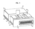
- the housing shown in Figure 1 for an electronic control device in vehicles comprises a generally parallelepipedal metallic housing shell 10 and a carrier structure 12 for electronic components of the control device.
- the housing shell 10 is cup-shaped with an open front face through which the carrier structure 12 can be inserted.
- the housing shell has parallel top and bottom walls and a pair of side walls 10a, 10b interconnecting the top and bottom walls.
- Side walls 10a , 10b are provided with parallel grooves 14 in which two corresponding lateral edges 16 of the carrier structure 12 engage.
- the grooves 14 are formed by outwardly projecting wall portions 22 of side walls 10a, 10b.
- the housing shell 10 is made of aluminum by means of flow pressing.
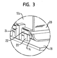
- the housing shell 10 is seated onto a base plate 18 and attached to it. On the edges of the base plate 18 corresponding to the side walls 10a, 10b, there are upright support members 20 on which the projecting wall portions 22 of housing shell 10 bear.
- a printed circuit board 28 is slid into the grooves 14 .
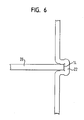
- the fastener elements 24 are caulked against the support members 20 , whereby the wall portions 22 of housing shell 10 are pinched and consequently the corresponding edge areas of the printed circuit board 28 are clamped.
- This situation is shown in an enlarged view in Figure 6.
- an electric ground connection between the printed circuit board and the housing shell is established while providing mechanical stability.
- electronic components of the control device are set up on the printed circuit board 28 .
- One of these components can be an acceleration sensor that is rigidly coupled to the base plate 18 via the printed circuit board and housing shell 10 .
- the base plate 18 has attachment openings 19 for anchoring the housing to a car body.
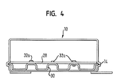
- the printed circuit board 28 is attached to a metallic carrier plate 30 .
- the cross section of the carrier plate 30 has a meander-shaped profile, with support surfaces lying against the printed circuit board and, spaced from the support surface, with support surfaces bearing on the bottom of housing shell 10.
- it is not the edge areas of the printed circuit board 28 but rather the edge areas of the carrier plate 30 that engage in the grooves 14. They are attached and contacted there in the same manner as was explained with reference to Figures 3 and 6.
- An electrically conductive connection between the metallic carrier plate 30 and the printed circuit board 28 is redundantly achieved at plural attachment points, such as the attachment points 32a in Figure 4.
- a mechanical support structure 34 is attached on the printed circuit board 28 on its side facing away from the bottom of the housing shell 10 .
- the cross section of the mechanical support structure 34 is generally meander-shaped, with upright support walls 36 bent up at a right angle, on which electronic components of the control device can be supported.
- the open front of housing shell 10 is closed by a front plate 40 that carries a plug socket 42 .
- the front plate 40 is attached to the carrier structure 12 .
- it is provided with angled tabs 44 , 46 on which the inner surface of the front plate 40 comes to rest.
- the housing is also suitable for control devices such as actuation devices in safety equipment of the vehicle which use an acceleration sensor set up on the printed circuit board.
- the electrical ground connection between the outer housing and the printed circuit board, which is needed for such applications, is also ensured.
Abstract
Description
- Electronic control devices in vehicles are exposed to high thermal and mechanical stress. Consequently, they require a sufficiently resistant housing. Especially high demands are made for the housings of control devices that involve an acceleration sensor and that serve to actuate safety equipment in the vehicle, such as a belt tensioner or an airbag. With such control devices, it must be possible to rigidly connect the housing to the car body and to transmit the occurring accelerations to the acceleration sensor. Moreover, for the reliable functioning of the electronic components of the control device, there must be a good ground connection between the housing and the car body on the one hand, as well as between the housing and the electronic control device on the other hand.
- These requirements are satisfied in conventional housings with heavy and bulky metallic constructions.
- The present invention provides a housing that satisfies the requirements of acceleration transmission and reliable ground connection with a simple and inexpensive construction. Specifically, the inventive housing comprises a metallic shell that has parallel top and bottom walls, opposed side walls interconnecting the top and bottom walls and an open front face. A shaped carrier structure has a pair of opposed lateral edges. Both side walls of the shell have an internal groove extending parallel to and spaced from the bottom wall of the shell. The carrier structure is accommodated within the shell and has its lateral edges fitted in the grooves of the side walls. In the preferred embodiment, the shell has its bottom wall attached to a metallic base plate. The grooves are formed by outwardly projecting wall portions and fastener members are provided that are attached to the base plate and engage the projecting wall portions. Preferably, the projecting wall portions are pressed onto the lateral edges of the carrier structure from two opposed sides to establish a secure attachment to the shell and simultaneously a reliable electrical ground connection. The lateral edges may be those of a printed circuit board whereon the electronic components of the device are mounted, or those of a folded sheet metal member on which the printed circuit board is mounted.
- The housing of the present invention can be made of just a few easily and inexpensively manufactured components that are assembled with just a few automated steps.
- Additional characteristics and advantages of the invention ensue from the description below of several embodiments and from the accompanying drawings to which reference is made. In the drawings:
- Figure 1 is an exploded perspective view of a housing consisting of a metallic shell and an internal carrier structure for electronic components that can be slid into the shell;
- Figure 2 is a perspective view of a housing shell seated on a base plate, with a printed circuit board slid in place;
- Figure 3 is an enlarged detail view from Figure 2;
- Figure 4 is a cross section of a particular housing embodiment;
- Figure 5 is a cross section of a carrier structure with a printed circuit board;
- Figure 6 is an enlarged detail view from Figure 2; and
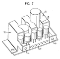
- Figure 7 is a perspective partial view of a carrier structure with electronic components and a printed circuit board attached to the structure.
-
- The housing shown in Figure 1 for an electronic control device in vehicles comprises a generally parallelepipedal
metallic housing shell 10 and acarrier structure 12 for electronic components of the control device. Thehousing shell 10 is cup-shaped with an open front face through which thecarrier structure 12 can be inserted. The housing shell has parallel top and bottom walls and a pair ofside walls Side walls parallel grooves 14 in which two correspondinglateral edges 16 of thecarrier structure 12 engage. Thegrooves 14 are formed by outwardly projectingwall portions 22 ofside walls housing shell 10 is made of aluminum by means of flow pressing. - The
housing shell 10 is seated onto abase plate 18 and attached to it. On the edges of thebase plate 18 corresponding to theside walls upright support members 20 on which the projectingwall portions 22 ofhousing shell 10 bear. - Parallel to the
support members 20 and along the corresponding edges of thebase plate 18, there areupright fastener elements 24 that engage around the outwardly protrudingwall portions 22 ofhousing shell 10. - In the embodiment shown in Figures 2 and 3, a printed
circuit board 28 is slid into thegrooves 14. In order to attach the printedcircuit board 28 in thegrooves 14 ofshell 10, thefastener elements 24 are caulked against thesupport members 20, whereby thewall portions 22 ofhousing shell 10 are pinched and consequently the corresponding edge areas of the printedcircuit board 28 are clamped. This situation is shown in an enlarged view in Figure 6. As a result of the pinching of the printedcircuit board 28 at its edge areas which are inserted into thegrooves 14, an electric ground connection between the printed circuit board and the housing shell is established while providing mechanical stability. - In the embodiment shown in Figure 2, electronic components of the control device are set up on the printed
circuit board 28. One of these components can be an acceleration sensor that is rigidly coupled to thebase plate 18 via the printed circuit board andhousing shell 10. Thebase plate 18 hasattachment openings 19 for anchoring the housing to a car body. - In the embodiment according to Figure 4, the printed
circuit board 28 is attached to ametallic carrier plate 30. The cross section of thecarrier plate 30 has a meander-shaped profile, with support surfaces lying against the printed circuit board and, spaced from the support surface, with support surfaces bearing on the bottom ofhousing shell 10. Unlike the embodiment of Figure 2, it is not the edge areas of the printedcircuit board 28 but rather the edge areas of thecarrier plate 30 that engage in thegrooves 14. They are attached and contacted there in the same manner as was explained with reference to Figures 3 and 6. An electrically conductive connection between themetallic carrier plate 30 and the printedcircuit board 28 is redundantly achieved at plural attachment points, such as theattachment points 32a in Figure 4. - As an alternative or in addition to the embodiment shown in Figure 4, as indicated in Figure 5, a
mechanical support structure 34 is attached on the printedcircuit board 28 on its side facing away from the bottom of thehousing shell 10. The cross section of themechanical support structure 34 is generally meander-shaped, withupright support walls 36 bent up at a right angle, on which electronic components of the control device can be supported. Figure 7, for example, shows a number of capacitors that are set up on the printedcircuit board 28 and supported by thesupport walls 36 of thesupport structure 34. - The open front of
housing shell 10 is closed by afront plate 40 that carries aplug socket 42. Thefront plate 40 is attached to thecarrier structure 12. In order to attach thefront plate 40 to thecarrier structure 12, it is provided withangled tabs front plate 40 comes to rest. - All of the embodiments have in common the fact that, in spite of the use of relatively easily and inexpensively manufactured components of the housing, a mechanically stiff structure is obtained. Therefore, the housing is also suitable for control devices such as actuation devices in safety equipment of the vehicle which use an acceleration sensor set up on the printed circuit board. The electrical ground connection between the outer housing and the printed circuit board, which is needed for such applications, is also ensured.
Claims (11)
- A housing for an electronic control device in vehicles, comprising a metallic shell that has parallel top and bottom walls, opposed side walls interconnecting said top and bottom walls and an open front face, and further comprising a shaped carrier structure that has a pair of opposed lateral edges, each of said side walls having an internal groove extending parallel to and spaced from said bottom wall, and said carrier structure being accommodated within said shell and having said lateral edges fitted in said grooves.
- The housing according to Claim 1, further comprising a metallic base plate, said shell being attached to said base plate.
- The housing of claim 2, wherein said grooves are formed by outwardly projecting wall portions and fastener members are provided that are attached to said base plate and engage said projecting wall portions.
- The housing of claim 3, wherein said projecting wall portions bear on support members carried by said base plate, and are clamped between said fastener members and said support members.
- The housing of claim 4, wherein said fastener members are pressed onto said projecting wall portions.
- The housing of claim 1, wherein said carrier structure comprises a printed circuit board and said lateral edges are those of said printed circuit board.
- The housing of claim 1, wherein said carrier structure comprises a folded sheet metal member and a printed circuit board attached to said sheet metal member, said lateral edges being provided on said sheet metal member.
- The housing of claim 1, wherein said projecting wall portions are pressed onto said lateral edges of the carrier structure from two opposed sides establishing an electrical ground connection between.
- The housing of claim 7, wherein said sheet metal member has first wall portions bearing on said bottom wall of the shell and second wall portions parallel to and spaced from said first wall portions, and the printed circuit board is attached to said second wall portions.
- The housing of claim 7, wherein said sheet metal member has wall portions erected on said printed circuit board to support electronic components of said control device.
- The housing of claim 1, wherein the open front face of said shell is closed by a front plate carrying a plug socket.
Priority Applications (1)
| Application Number | Priority Date | Filing Date | Title |
|---|---|---|---|
| EP08000088A EP1901596B1 (en) | 2001-09-24 | 2002-09-24 | Housing for an electronic control device in vehicles |
Applications Claiming Priority (2)
| Application Number | Priority Date | Filing Date | Title |
|---|---|---|---|
| DE20115659U DE20115659U1 (en) | 2001-09-24 | 2001-09-24 | Housing for an electronic control unit in vehicles |
| DE20115659U | 2001-09-24 |
Related Child Applications (1)
| Application Number | Title | Priority Date | Filing Date |
|---|---|---|---|
| EP08000088A Division EP1901596B1 (en) | 2001-09-24 | 2002-09-24 | Housing for an electronic control device in vehicles |
Publications (3)
| Publication Number | Publication Date |
|---|---|
| EP1296546A2 true EP1296546A2 (en) | 2003-03-26 |
| EP1296546A3 EP1296546A3 (en) | 2006-02-15 |
| EP1296546B1 EP1296546B1 (en) | 2009-07-29 |
Family
ID=7962043
Family Applications (2)
| Application Number | Title | Priority Date | Filing Date |
|---|---|---|---|
| EP08000088A Expired - Lifetime EP1901596B1 (en) | 2001-09-24 | 2002-09-24 | Housing for an electronic control device in vehicles |
| EP02021372A Expired - Lifetime EP1296546B1 (en) | 2001-09-24 | 2002-09-24 | Housing for an electronic control device in vehicles |
Family Applications Before (1)
| Application Number | Title | Priority Date | Filing Date |
|---|---|---|---|
| EP08000088A Expired - Lifetime EP1901596B1 (en) | 2001-09-24 | 2002-09-24 | Housing for an electronic control device in vehicles |
Country Status (4)
| Country | Link |
|---|---|
| US (1) | US7230821B2 (en) |
| EP (2) | EP1901596B1 (en) |
| JP (1) | JP2003175780A (en) |
| DE (2) | DE20115659U1 (en) |
Families Citing this family (13)
| Publication number | Priority date | Publication date | Assignee | Title |
|---|---|---|---|---|
| DE102004003180A1 (en) * | 2004-01-22 | 2005-08-18 | Robert Bosch Gmbh | Component such as a sensor in a vehicle with a housing and an electrical connector in its cover |
| JP2008192800A (en) * | 2007-02-05 | 2008-08-21 | Teac Corp | Electronic equipment |
| JP4638923B2 (en) * | 2008-03-31 | 2011-02-23 | 日立オートモティブシステムズ株式会社 | Control device |
| DE102008054384A1 (en) * | 2008-12-08 | 2010-06-10 | Robert Bosch Gmbh | Electrical circuit arrangement and method for producing an electrical circuit arrangement |
| DE102009059010A1 (en) * | 2009-12-17 | 2011-06-22 | Phoenix Contact GmbH & Co. KG, 32825 | module unit |
| DE102011009156A1 (en) * | 2011-01-22 | 2012-07-26 | Conti Temic Microelectronic Gmbh | Sensor assembly |
| JP5413443B2 (en) * | 2011-12-12 | 2014-02-12 | 株式会社デンソー | Electronic equipment |
| JP5440599B2 (en) * | 2011-12-28 | 2014-03-12 | 株式会社デンソー | Electronic equipment |
| JP6146131B2 (en) * | 2013-05-22 | 2017-06-14 | 株式会社デンソー | Electronic control unit and protective case |
| DE102013226060B4 (en) | 2013-12-16 | 2022-06-23 | Robert Bosch Gmbh | Electrical device with a variable housing and method for producing an electrical device |
| US9293870B1 (en) * | 2015-03-10 | 2016-03-22 | Continental Automotive Systems, Inc. | Electronic control module having a cover allowing for inspection of right angle press-fit pins |
| CN107444463B (en) | 2016-05-25 | 2021-05-14 | 均胜安全系统日本株式会社 | Steering wheel |
| JP2019169654A (en) * | 2018-03-26 | 2019-10-03 | 矢崎総業株式会社 | Electronic component module, electric connection box and electric connection box |
Citations (4)
| Publication number | Priority date | Publication date | Assignee | Title |
|---|---|---|---|---|
| DE19612063A1 (en) * | 1996-03-27 | 1997-10-02 | Bayerische Motoren Werke Ag | Electric control device for vehicle |
| DE19700558C1 (en) * | 1997-01-10 | 1998-06-25 | Fischer Elektronik Gmbh & Co K | Housings for electronic components |
| DE19924344A1 (en) * | 1999-05-27 | 2000-12-21 | Siemens Ag | Electric or electronic device housing especially for motor vehicle CB equipment |
| US6275385B1 (en) * | 1998-12-18 | 2001-08-14 | Denso Corporation | Electronic control device and jig device therefor having casing inclination compensating part |
Family Cites Families (12)
| Publication number | Priority date | Publication date | Assignee | Title |
|---|---|---|---|---|
| DE1845840U (en) | 1961-07-25 | 1962-02-01 | Bbc Brown Boveri & Cie | COVER PLATE FOR PRINTED CIRCUITS. |
| DE1847846U (en) | 1961-08-03 | 1962-03-08 | Bbc Brown Boveri & Cie | TWO-PIECE HOUSING. |
| DE4038788A1 (en) | 1990-12-05 | 1992-06-11 | Bsg Schalttechnik | HOUSING FOR ELECTRICAL CIRCUITS |
| US5563450A (en) * | 1995-01-27 | 1996-10-08 | National Semiconductor Corporation | Spring grounding clip for computer peripheral card |
| US5756948A (en) * | 1996-12-31 | 1998-05-26 | Breed Automotive Technology, Inc. | Side-impact electro-mechanical accelerometer to actuate a vehicular safety device |
| DE19722602C2 (en) | 1997-05-30 | 2001-03-29 | Lenze Gmbh & Co Kg Aerzen | Heat-dissipating housing for holding electrical or electronic components |
| US6191950B1 (en) * | 1998-12-15 | 2001-02-20 | International Business Machines Corporation | Snap-together printed circuit card cover with integral card support |
| US6361063B1 (en) * | 1999-03-18 | 2002-03-26 | Douglas Lincoln Daeschner | Portage device |
| DE29918914U1 (en) * | 1999-10-27 | 2000-03-09 | Trw Automotive Electron & Comp | Control device for occupant restraint systems in vehicles |
| FR2803166B1 (en) * | 1999-12-28 | 2002-05-31 | Thomson Csf Sextant | ELECTRONIC MODULE WITH HIGH COOLING POWER |
| JP4366863B2 (en) | 2000-02-02 | 2009-11-18 | 株式会社デンソー | Electronic control unit |
| US6473298B1 (en) * | 2000-08-30 | 2002-10-29 | Sun Microsystems, Inc. | Peripheral device storage system |
-
2001
- 2001-09-24 DE DE20115659U patent/DE20115659U1/en not_active Expired - Lifetime
-
2002
- 2002-09-24 JP JP2002276664A patent/JP2003175780A/en active Pending
- 2002-09-24 EP EP08000088A patent/EP1901596B1/en not_active Expired - Lifetime
- 2002-09-24 EP EP02021372A patent/EP1296546B1/en not_active Expired - Lifetime
- 2002-09-24 US US10/253,442 patent/US7230821B2/en not_active Expired - Fee Related
- 2002-09-24 DE DE60233097T patent/DE60233097D1/en not_active Expired - Lifetime
Patent Citations (4)
| Publication number | Priority date | Publication date | Assignee | Title |
|---|---|---|---|---|
| DE19612063A1 (en) * | 1996-03-27 | 1997-10-02 | Bayerische Motoren Werke Ag | Electric control device for vehicle |
| DE19700558C1 (en) * | 1997-01-10 | 1998-06-25 | Fischer Elektronik Gmbh & Co K | Housings for electronic components |
| US6275385B1 (en) * | 1998-12-18 | 2001-08-14 | Denso Corporation | Electronic control device and jig device therefor having casing inclination compensating part |
| DE19924344A1 (en) * | 1999-05-27 | 2000-12-21 | Siemens Ag | Electric or electronic device housing especially for motor vehicle CB equipment |
Also Published As
| Publication number | Publication date |
|---|---|
| EP1901596A3 (en) | 2008-07-09 |
| US7230821B2 (en) | 2007-06-12 |
| EP1901596A2 (en) | 2008-03-19 |
| US20030174472A1 (en) | 2003-09-18 |
| DE20115659U1 (en) | 2002-02-14 |
| JP2003175780A (en) | 2003-06-24 |
| EP1296546B1 (en) | 2009-07-29 |
| DE60233097D1 (en) | 2009-09-10 |
| EP1296546A3 (en) | 2006-02-15 |
| EP1901596B1 (en) | 2011-08-31 |
Similar Documents
| Publication | Publication Date | Title |
|---|---|---|
| EP1901596B1 (en) | Housing for an electronic control device in vehicles | |
| EP3422485B1 (en) | Connector and connection structure of connector and metal casing | |
| EP1296545B1 (en) | Housing for an electronic control device in vehicles | |
| EP1675222B1 (en) | Connection terminal and connector equipped therewith | |
| KR100592360B1 (en) | Board Embedded Press Contacts | |
| WO2005011060A3 (en) | Electrical interconnect assembly with interlocking contact system | |
| US20070270019A1 (en) | Connecting structure of electric wire and electronic-component incorporating unit | |
| US6042431A (en) | Joint device for an automotive wiring harness | |
| US7252544B2 (en) | Connector having a U-shaped fixing member with screw holes | |
| US5615944A (en) | Automotive dome light arrangement | |
| US5535098A (en) | Electrical device, particularly switching and control device for motor vehicles | |
| US6083045A (en) | Electrical connector | |
| US6719571B2 (en) | Housing with an electrical circuit accommodated therein | |
| US6068493A (en) | Electrical connector for flexible film | |
| JP5256842B2 (en) | Composite connector for memory card | |
| US5629504A (en) | Voltage switch | |
| CN109155456B (en) | Communication device for a diagnostic system of a motor vehicle | |
| US6565378B1 (en) | Electrical connector terminal and housing | |
| US6109932A (en) | Three-dimensional electrical interconnection system | |
| JP3974506B2 (en) | Board built-in pressure contact connector | |
| JP2696305B2 (en) | Connector mounting device | |
| JPH0635356Y2 (en) | Attachment mounting structure | |
| KR101897076B1 (en) | Elctronic control device having connector coupling structure | |
| US20100255692A1 (en) | Electrical connection system | |
| JPH0654239U (en) | Attachment mounting structure |
Legal Events
| Date | Code | Title | Description |
|---|---|---|---|
| PUAI | Public reference made under article 153(3) epc to a published international application that has entered the european phase |
Free format text: ORIGINAL CODE: 0009012 |
|
| AK | Designated contracting states |
Kind code of ref document: A2 Designated state(s): AT BE BG CH CY CZ DE DK EE ES FI FR GB GR IE IT LI LU MC NL PT SE SK TR |
|
| AX | Request for extension of the european patent |
Extension state: AL LT LV MK RO SI |
|
| PUAL | Search report despatched |
Free format text: ORIGINAL CODE: 0009013 |
|
| AK | Designated contracting states |
Kind code of ref document: A3 Designated state(s): AT BE BG CH CY CZ DE DK EE ES FI FR GB GR IE IT LI LU MC NL PT SE SK TR |
|
| AX | Request for extension of the european patent |
Extension state: AL LT LV MK RO SI |
|
| 17P | Request for examination filed |
Effective date: 20060810 |
|
| AKX | Designation fees paid |
Designated state(s): CZ DE FR GB IT |
|
| 17Q | First examination report despatched |
Effective date: 20070705 |
|
| RAP1 | Party data changed (applicant data changed or rights of an application transferred) |
Owner name: TRW AUTOMOTIVE ELECTRONICS & COMPONENTS GMBH |
|
| GRAP | Despatch of communication of intention to grant a patent |
Free format text: ORIGINAL CODE: EPIDOSNIGR1 |
|
| GRAS | Grant fee paid |
Free format text: ORIGINAL CODE: EPIDOSNIGR3 |
|
| GRAA | (expected) grant |
Free format text: ORIGINAL CODE: 0009210 |
|
| AK | Designated contracting states |
Kind code of ref document: B1 Designated state(s): CZ DE FR GB IT |
|
| REG | Reference to a national code |
Ref country code: GB Ref legal event code: FG4D |
|
| REF | Corresponds to: |
Ref document number: 60233097 Country of ref document: DE Date of ref document: 20090910 Kind code of ref document: P |
|
| PGFP | Annual fee paid to national office [announced via postgrant information from national office to epo] |
Ref country code: GB Payment date: 20090923 Year of fee payment: 8 |
|
| PGFP | Annual fee paid to national office [announced via postgrant information from national office to epo] |
Ref country code: CZ Payment date: 20090917 Year of fee payment: 8 |
|
| PGFP | Annual fee paid to national office [announced via postgrant information from national office to epo] |
Ref country code: FR Payment date: 20091012 Year of fee payment: 8 Ref country code: IT Payment date: 20090917 Year of fee payment: 8 |
|
| PLBE | No opposition filed within time limit |
Free format text: ORIGINAL CODE: 0009261 |
|
| STAA | Information on the status of an ep patent application or granted ep patent |
Free format text: STATUS: NO OPPOSITION FILED WITHIN TIME LIMIT |
|
| 26N | No opposition filed |
Effective date: 20100503 |
|
| GBPC | Gb: european patent ceased through non-payment of renewal fee |
Effective date: 20100924 |
|
| PG25 | Lapsed in a contracting state [announced via postgrant information from national office to epo] |
Ref country code: CZ Free format text: LAPSE BECAUSE OF NON-PAYMENT OF DUE FEES Effective date: 20100924 Ref country code: IT Free format text: LAPSE BECAUSE OF NON-PAYMENT OF DUE FEES Effective date: 20100924 |
|
| REG | Reference to a national code |
Ref country code: FR Ref legal event code: ST Effective date: 20110531 |
|
| PG25 | Lapsed in a contracting state [announced via postgrant information from national office to epo] |
Ref country code: FR Free format text: LAPSE BECAUSE OF NON-PAYMENT OF DUE FEES Effective date: 20100930 |
|
| PG25 | Lapsed in a contracting state [announced via postgrant information from national office to epo] |
Ref country code: GB Free format text: LAPSE BECAUSE OF NON-PAYMENT OF DUE FEES Effective date: 20100924 |
|
| PGFP | Annual fee paid to national office [announced via postgrant information from national office to epo] |
Ref country code: DE Payment date: 20130927 Year of fee payment: 12 |
|
| REG | Reference to a national code |
Ref country code: DE Ref legal event code: R119 Ref document number: 60233097 Country of ref document: DE |
|
| PG25 | Lapsed in a contracting state [announced via postgrant information from national office to epo] |
Ref country code: DE Free format text: LAPSE BECAUSE OF NON-PAYMENT OF DUE FEES Effective date: 20150401 |