EP1296730B2 - Injection device - Google Patents
Injection device Download PDFInfo
- Publication number
- EP1296730B2 EP1296730B2 EP01908589.3A EP01908589A EP1296730B2 EP 1296730 B2 EP1296730 B2 EP 1296730B2 EP 01908589 A EP01908589 A EP 01908589A EP 1296730 B2 EP1296730 B2 EP 1296730B2
- Authority
- EP
- European Patent Office
- Prior art keywords
- housing
- opening
- propellant
- sleeve
- piston
- Prior art date
- Legal status (The legal status is an assumption and is not a legal conclusion. Google has not performed a legal analysis and makes no representation as to the accuracy of the status listed.)
- Expired - Lifetime
Links
Images


Classifications
-
- A—HUMAN NECESSITIES
- A61—MEDICAL OR VETERINARY SCIENCE; HYGIENE
- A61M—DEVICES FOR INTRODUCING MEDIA INTO, OR ONTO, THE BODY; DEVICES FOR TRANSDUCING BODY MEDIA OR FOR TAKING MEDIA FROM THE BODY; DEVICES FOR PRODUCING OR ENDING SLEEP OR STUPOR
- A61M5/00—Devices for bringing media into the body in a subcutaneous, intra-vascular or intramuscular way; Accessories therefor, e.g. filling or cleaning devices, arm-rests
- A61M5/48—Devices for bringing media into the body in a subcutaneous, intra-vascular or intramuscular way; Accessories therefor, e.g. filling or cleaning devices, arm-rests having means for varying, regulating, indicating or limiting injection pressure
- A61M5/484—Regulating injection pressure
-
- A—HUMAN NECESSITIES
- A61—MEDICAL OR VETERINARY SCIENCE; HYGIENE
- A61M—DEVICES FOR INTRODUCING MEDIA INTO, OR ONTO, THE BODY; DEVICES FOR TRANSDUCING BODY MEDIA OR FOR TAKING MEDIA FROM THE BODY; DEVICES FOR PRODUCING OR ENDING SLEEP OR STUPOR
- A61M5/00—Devices for bringing media into the body in a subcutaneous, intra-vascular or intramuscular way; Accessories therefor, e.g. filling or cleaning devices, arm-rests
- A61M5/178—Syringes
- A61M5/30—Syringes for injection by jet action, without needle, e.g. for use with replaceable ampoules or carpules
-
- A—HUMAN NECESSITIES
- A61—MEDICAL OR VETERINARY SCIENCE; HYGIENE
- A61M—DEVICES FOR INTRODUCING MEDIA INTO, OR ONTO, THE BODY; DEVICES FOR TRANSDUCING BODY MEDIA OR FOR TAKING MEDIA FROM THE BODY; DEVICES FOR PRODUCING OR ENDING SLEEP OR STUPOR
- A61M5/00—Devices for bringing media into the body in a subcutaneous, intra-vascular or intramuscular way; Accessories therefor, e.g. filling or cleaning devices, arm-rests
- A61M5/178—Syringes
- A61M5/31—Details
- A61M2005/3123—Details having air entrapping or venting means, e.g. purging channels in pistons
-
- A—HUMAN NECESSITIES
- A61—MEDICAL OR VETERINARY SCIENCE; HYGIENE
- A61M—DEVICES FOR INTRODUCING MEDIA INTO, OR ONTO, THE BODY; DEVICES FOR TRANSDUCING BODY MEDIA OR FOR TAKING MEDIA FROM THE BODY; DEVICES FOR PRODUCING OR ENDING SLEEP OR STUPOR
- A61M5/00—Devices for bringing media into the body in a subcutaneous, intra-vascular or intramuscular way; Accessories therefor, e.g. filling or cleaning devices, arm-rests
- A61M5/178—Syringes
- A61M5/31—Details
- A61M2005/3128—Incorporating one-way valves, e.g. pressure-relief or non-return valves
-
- A—HUMAN NECESSITIES
- A61—MEDICAL OR VETERINARY SCIENCE; HYGIENE
- A61M—DEVICES FOR INTRODUCING MEDIA INTO, OR ONTO, THE BODY; DEVICES FOR TRANSDUCING BODY MEDIA OR FOR TAKING MEDIA FROM THE BODY; DEVICES FOR PRODUCING OR ENDING SLEEP OR STUPOR
- A61M5/00—Devices for bringing media into the body in a subcutaneous, intra-vascular or intramuscular way; Accessories therefor, e.g. filling or cleaning devices, arm-rests
- A61M5/178—Syringes
- A61M5/20—Automatic syringes, e.g. with automatically actuated piston rod, with automatic needle injection, filling automatically
- A61M5/2046—Media being expelled from injector by gas generation, e.g. explosive charge
-
- A—HUMAN NECESSITIES
- A61—MEDICAL OR VETERINARY SCIENCE; HYGIENE
- A61M—DEVICES FOR INTRODUCING MEDIA INTO, OR ONTO, THE BODY; DEVICES FOR TRANSDUCING BODY MEDIA OR FOR TAKING MEDIA FROM THE BODY; DEVICES FOR PRODUCING OR ENDING SLEEP OR STUPOR
- A61M5/00—Devices for bringing media into the body in a subcutaneous, intra-vascular or intramuscular way; Accessories therefor, e.g. filling or cleaning devices, arm-rests
- A61M5/178—Syringes
- A61M5/30—Syringes for injection by jet action, without needle, e.g. for use with replaceable ampoules or carpules
- A61M5/3007—Syringes for injection by jet action, without needle, e.g. for use with replaceable ampoules or carpules with specially designed jet passages at the injector's distal end
Definitions
- the invention relates to injection devices (e.g., injection devices including a needleless syringe), as well as components that can be used in injection devices.
- injection devices can be used for fluid injection into a body.
- Some injection devices can include a needleless syringe.
- WO 98/31409 A discloses an injection device comprising a housing having a proximal end and a distal end, the housing defining a distal opening, and a first opening in a side of the housing and between the proximal and distal ends; a propellant disposed inside the housing and spaced from the distal end; and a movable member disposed inside the housing and between the distal end and the propellant, wherein the propellant is in fluid communication with the movable member and the first opening.
- the present invention provides an injection device according to the characterising portion of claim 1.
- the invention provides one or more components (e. g., a gas generant unit and/or a housing unit) that can be used in an injection device (e. g., an injection device including a needleless syringe), and injection devices containing one or more of these components.
- an injection device e. g., an injection device including a needleless syringe
- injection devices containing one or more of these components can be removable, replaceable and/or adaptable to fit different sized injection devices.
- the injection devices can be re-usable.
- the injection devices can be in any of a variety of shapes and sizes.
- the gas generant unit can be removed before or after use of the injection device.
- a gas generant unit that is removed from the syringe can be replaced with a different gas generant unit, which may contain the same or different gas generant compounds.
- a gas generant unit can be adaptable to fit different sized injection devices. Advantages associated with an injection device that is capable of using such a gas generant can include re-usability, relatively low cost to manufacture, relatively low cost to use, and/or enhanced flexibility in materials used as gas generant and/or injection fluid.
- the injection device can include a housing that allows a fluid (e. g., a gas, such as a product of the reaction of the gas generant) to travel between the interior of the injection device and the exterior of the injection device without passing through the distal end of the injection device (e. g., the exit port of a syringe, such as a needleless syringe, contained within the injection device).
- a fluid e. g., a gas, such as a product of the reaction of the gas generant
- this feature can be provided, for example, by including the following components in the housing: a sliding piston, a sleeve (which can have one or more venting mechanisms, such as one or more venting grooves, e.g., annular venting groove(s)), and one or more pressure relief mechanisms (e.g., one or more pressure relief holes).
- the sliding piston can be designed to move along the sleeve so that, at one or more points along the path of motion of the sliding piston, the pressure relief mechanism(s) of the sliding piston align (e.g., partially align or fully align) with the pressure relief mechanism(s) in the sleeve.
- the fluid e.g., reactant gas
- the fluid e.g., reactant gas
- a passageway that does not include the distal end of the injection device (e.g., the exit port of a syringe, such as a needleless syringe, contained within the injection device).
- the invention features an injection device, such as a needleless injection device, having a housing having a proximal end and a distal end, the housing defining a distal opening, and a first opening in a side of the housing and between the proximal and distal ends; a propellant disposed inside the housing and spaced from the distal end; and a movable member disposed inside the housing and between the distal end and the propellant, wherein the propellant is in fluid communication with the movable member and the first opening.
- a needleless injection device having a housing having a proximal end and a distal end, the housing defining a distal opening, and a first opening in a side of the housing and between the proximal and distal ends; a propellant disposed inside the housing and spaced from the distal end; and a movable member disposed inside the housing and between the distal end and the propellant, wherein the propellant is in fluid communication with the movable member and the first opening.
- Embodiments include one or more of the following features.
- the propellant is capable of forming a gas capable of moving the movable member in a distal direction and flowing through the first opening to the exterior of the housing.
- the movable member comprises a piston defining a cavity, and the propellant is in fluid communication with the cavity.
- the movable member further defines a second opening in fluid communication with the first opening.
- the device further includes a hollow sleeve configured to mate with the piston, the sleeve defining a second cavity in fluid communication with the propellant.
- the sleeve further defines a third opening alignable with the second opening.
- the sleeve further defines a groove, and the third opening is disposed in the groove.
- the device further includes a button at the proximal end of the housing; a battery inside the housing and adjacent to the button; electrical leads in electrical communication with the battery; and a wire in electrical communication with the electrical leads, the wire configured to trigger the propellant.
- the distal opening of the housing is configured to mate with a proximal end of a syringe.
- the syringe includes a plunger, and the movable member is configured to move the plunger in a distal direction.
- the propellant includes a chemical pyrotechnic material.
- the housing is composed of a plurality of detachable housings.
- the invention features an injection device, such as a needleless injection device, having a housing having a proximal end and a distal end, the housing defining a distal opening, and a first opening in a side of the housing and between the proximal and distal ends; a propellant disposed inside the housing and spaced from the distal end; a sleeve disposed inside the housing and between the distal end and the propellant, the sleeve defining a second opening and a first cavity, the second opening and the first cavity in fluid communication with the propellant; and a piston mateable with the sleeve and movable in a distal direction, the piston defining a third opening alignable with the second opening, wherein the propellant is in fluid communication with the first opening when the second and third openings are aligned.
- a needleless injection device having a housing having a proximal end and a distal end, the housing defining a distal opening, and a first opening in a side
- Embodiments include one or more of the following features.
- the propellant is capable of forming a gas capable of flowing through the first cavity to move the piston, wherein the gas flows through the second and third openings when aligned, and through the first opening.
- the propellant includes a chemical pyrotechnic material.
- the piston is coaxial with the sleeve and slidable over the sleeve to align the second and third openings.
- the piston defines a plurality of openings alignable with the second opening.
- the sleeve defines a groove, such as an annular groove, the second opening disposed in the groove.
- the distal opening of the housing is configured to mate with a syringe having a plunger, and the piston is configured to move the plunger.
- the device further includes a button at the proximal end of the housing; a battery inside the housing and adjacent to the button; electrical leads in electrical communication with the battery; and a wire in electrical communication with the electrical leads, the wire configured to trigger the propellant.
- the housing further defines an elongate passageway between the first opening and the third opening.
- the device further includes a filter between the propellant and the first cavity.
- the housing is composed of a plurality of detachable housings.
- the invention features an apparatus that includes a housing, a button connected to the housing, a battery adjacent the button and connected to the housing, electrical leads in electrical communication with the battery, and a wire in electrical communication with the electrical leads.
- the invention features an apparatus that includes a sleeve having a surface having at least one hole, a movable piston having at least one hole and a surface adjacent the surface of the sleeve, and a first housing connected to the sleeve and the movable piston.
- the invention features an injection device including first, second, third and fourth housings.
- the first housing is demountably attached to the second housing.
- the second housing is demountably attached to the third housing.
- the third housing is demountably attached to the fourth housing.
- the first housing includes a button and a battery adjacent the button.
- the second housing includes an inner housing, electrical contacts within the inner housing, a wire within the inner housing and in electrical communication with the electrical contacts, and a gas generant within the inner housing.
- the third housing includes a syringe adaptor housing having an outer vent sleeve, a movable piston having an end and at least one relief hole, a fixed sleeve having a groove with a hole (e.g., a pressure relief hole), the fixed sleeve being adjacent the movable piston, a drive piston having at least one groove, the drive piston being adjacent the end of the movable piston and a sealing device within the groove of the drive piston.
- the fourth housing includes a plunger having an end, a syringe adjacent the end of the plunger, and an elastomeric spring adjacent the syringe.
- the invention relates to injection devices (e.g., injection devices containing needleless syringes) and components that can be used in such injection devices.
- Advantages of the injection devices can include that they are relatively safe to use, relatively less painful to use, capable of delivering fluid in a predetermined and/or desirable manner, and/or re-usable.
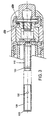
- Fig. 1 shows a cross-sectional view of an embodiment of an injection device 5.
- Device 5 includes housings 10, 20, 30 and 200.
- Housing 10 is demountably attached to housing 20 at section 250 by, for example, screw threads or a bayonet lock.
- Housing 20 is demountably attached to housing 30 at section 260 by, for example, screw threads or a bayonet lock.
- Housing 30 is permanently attached to a bayonet interlock syringe housing adaptor 200 to provide a mechanism for fitting a syringe configuration.
- Housing 10 includes a button 40, a battery 50, and an electrically insulative (e.g., non-metallic) cup 620 ( Fig. 3 ).
- electrically insulative e.g., non-metallic
- Housing 20 encloses a housing 80 (e.g., a disposable housing) having electrical contacts 60, a wire 70 and a propellant 90, such as a gas generant ( Fig. 2 ).
- Housing 30 includes a syringe adaptor housing 200 having an outer vent sleeve 150, a sliding piston 100 having pressure relief holes 130, sleeve 110 (e.g., a fixed sleeve) having a groove 120 (e.g., an annular groove), and a drive piston 170 having grooves containing sealing devices 180 (e.g., o-rings) and a syringe interface 190 (e.g., a custom syringe interface) located at its distal end ( Fig. 3 ).
- sealing devices 180 e.g., o-rings
- a syringe interface 190 e.g., a custom syringe interface
- assembly 30 is assembled as follows.
- Sleeve 110 is permanently attached to housing 30, followed by permanently attached outer vent sleeve 150 to the flange of sleeve 110.
- elastomeric spring 210 is bonded to the end of housing 30, and syringe adaptor 200 is subsequently permanently attached to housing 30.
- Syringe adaptor 200 accepts a syringe housing 220 with its associated plunger 230.
- Fig. 2 shows an exploded view of an embodiment of housing 80 including electrical contacts 60, wire 70, propellant 90, screen 240, filter 250 and cap 260 with an exit hole 270.
- Fig. 3 shows an exploded view of an embodiment of sleeve 110, annular groove 120 having hole(s) 300, sliding piston 100 and vent holes 130.
- button 40 e.g., a molded plastic button
- a wave spring 610 which causes battery 50 (e.g., a replaceable battery) to come into contact with electrical contacts 60.
- This causes an electrical current to pass through wire 70 (e.g., a metal wire such as nickel/chromium wire, and/or a wire having a diameter of from about 0.127mm (0.005 inch to about 0.254mm (0.010 inch, such as about 0.254mm (0.010 inch), thereby heating wire 70 (e.g., causing wire 70 to become red hot in about one second).
- the heat generated by wire 70 is sufficient to cause the reaction of chemical components contained in propellant 90.
- Such chemical components can include a fuel and an oxidant.
- a nonlimiting, illustrative list of examples of chemical components that can be used in propellant 90 are disclosed in U.S. Patent Nos. 4,103,684 ; 4,342,310 ; 4,447,225 ; 4,518,385 ; 4,592,742 ; 4,623,332 ; 4,680,027 ; 4,722,728 ; 4,913,699 ; 5,024,656 ; 5,049,125 ; 5,064,123 ; 5,190,523 ; 5,304,128 ; 5,312,335 ; 5,334,144 ; 5,383,851 ; 5,399,163 ; 5,499,972 ; 5,501,666 ; 5,503,628 ; 5,520,639 ; 5,569,189 ; 5,630,796 ; 5,704,911 ; 5,730,723 ; 5,840,061 ; 5,851,198 ; 5,879,327 ; 5,899
- the gas formed by the reaction of the chemical components in propellant 90 passes through screen 240 (e.g., metal screen, such as a stainless steel screen of, for example, about 50 to 200 mesh) and filter 250 (e.g., a glass fiber filter).
- Screen 240 can cool the reactant gas and/or trap slag, and filter 250 can trap particulates (e.g., small particulates, such as those generated during the reaction).
- piston 100 After passing through filter 250, the reactant gases cause sliding piston 100 to move along the surface of sleeve 110. As piston 100 moves along the surface of sleeve 110, piston 100 urges drive piston 170 to push against plunger 230 which, in turn, pushes against fluid within syringe 220, thereby ejecting fluid from syringe 220 via outlet 310.
- the movement of piston 100 along the surface of sleeve 110 also causes holes 130 to reach ring 120.
- the reactant gas can pass through one or more holes 300 (e.g., one, two, three or four holes) in ring 120 and one or more of holes 130.
- the reactant gas that passes through holes 300 and hole(s) 130 can flow through relief channels 140, into space 160 (e.g., an open space, or a space containing a filter material, such as glass wool) and out device 5 via gas vent 7.
- the number, size and location of holes 130 can vary to assist in controlling the pressure of fluid exiting through distal end 310 of syringe 5.
- the location of holes 130 can be determined by interfacing the end of the syringe to a pressure transducer that in turn is interfaced to a real time data acquisition system.
- a pressure transducer that in turn is interfaced to a real time data acquisition system.
- a model PCI-730/6040E data acquisition board commercially available from National Instruments of Austin, TX
- a computer e.g., a personal computer
- Changes in the pressure profile due to changes in the placement, shape and size of holes 130 can be monitored and optimized accordingly.
- annular groove 120 can obviate the need for a precise alignment of holes 130 because holes 130 are not required to be keyed to contact groove 120.
- Syringe 220 and plunger 230 can take on a variety of shapes and sizes.
- syringe 220 and plunger 230 can be commercially available components (e.g., such as available from Bioject Medical, located in Portland, OR; Injet Medical Products, Inc., located in Lake Forest, IL; and Avant Drug Delivery Systems, Inc., located in San Diego, CA).
- interlock The end of housing 30, syringe adaptor 200 and elastomeric spring 210 form an interlock, which, in certain embodiments, can be designed to accept the attachment of commercially available syringes and/or ampules.
- the interlock may be one of several types including a bayonet type.
- housing 80 is replaceable. In these embodiments, after an injection housing 80 can be removed and replaced with a different housing, and device 5 can be re-used.
- housings 10, 20, 30 and/or 300 can be non-demountable.
- the invention provides for the delivery of a mixture of two substances.
- the first substance can be a dry substance, e.g., a lyophilized protein, nucleic acid, e.g., RNA or DNA, or polysaccharide.
- the first substance can be a vaccine, or a drug.
- the first substance can be a peptide, polypeptide, or protein, e.g., an antibody, an enzyme, a hormone or growth factor.
- Preferred first substances include insulin.
- the first substance can be: a blood protein, e.g., clotting factor VIII or a IX, complement factor or component; a hormone, e.g., insulin, growth hormone, thyroid hormone, a catecholamine, a gonadotrophin, PMSG, a trophic hormone, prolactin, oxytocin, dopamine and the like; a growth factor, e.g., EGF, PDGF, NGF, IGF's and the like; a cytokine, e.g., an, interleukin, CSF, GMCSF, TNF, TGF-alpha, TGF-beta.
- a blood protein e.g., clotting factor VIII or a IX, complement factor or component
- a hormone e.g., insulin, growth hormone, thyroid hormone, a catecholamine, a gonadotrophin, PMSG, a trophic hormone, prolactin, oxytocin, dopamine and the like
- an enzyme e.g., tissue plasminogen activator, streptokinase, cholesterol biosynthetic or degradative, glycosolases, and the like
- a binding protein e.g., a steroid binding protein, a growth hormone or growth factor binding protein and the like
- an immune system protein e.g., an antibody, SLA or MHC gene or gene product
- an antigen e.g., a bacterial, parasitic, or viral, substance or generally allergens and the like.
- the second substance can be a liquid, e.g., a diluent or solute.
- liquids can include buffers, inert fillers, pharmaceutically acceptable carriers, or the like.
- the subject can be a human or an animal, e.g., a laboratory animal, or pet, e.g., a dog or cat, or other animal, e.g., a bovine, a swine, a goat, or a horse.
- the first and second substance can be combined by the subject, or by another person.
Abstract
Description
- The invention relates to injection devices (e.g., injection devices including a needleless syringe), as well as components that can be used in injection devices. Injection devices can be used for fluid injection into a body. Some injection devices can include a needleless syringe.
-
WO 98/31409 A - The present invention provides an injection device according to the characterising portion of claim 1.
- The invention provides one or more components (e. g., a gas generant unit and/or a housing unit) that can be used in an injection device (e. g., an injection device including a needleless syringe), and injection devices containing one or more of these components. The components can be removable, replaceable and/or adaptable to fit different sized injection devices. The injection devices can be re-usable. The injection devices can be in any of a variety of shapes and sizes.
- For embodiments in which the injection device includes a gas generant unit, the gas generant unit can be removed before or after use of the injection device.
- Moreover, a gas generant unit that is removed from the syringe can be replaced with a different gas generant unit, which may contain the same or different gas generant compounds. Furthermore, a gas generant unit can be adaptable to fit different sized injection devices. Advantages associated with an injection device that is capable of using such a gas generant can include re-usability, relatively low cost to manufacture, relatively low cost to use, and/or enhanced flexibility in materials used as gas generant and/or injection fluid.
- The injection device can include a housing that allows a fluid (e. g., a gas, such as a product of the reaction of the gas generant) to travel between the interior of the injection device and the exterior of the injection device without passing through the distal end of the injection device (e. g., the exit port of a syringe, such as a needleless syringe, contained within the injection device). In certain embodiments, this feature can be provided, for example, by including the following components in the housing: a sliding piston, a sleeve (which can have one or more venting mechanisms, such as one or more venting grooves, e.g., annular venting groove(s)), and one or more pressure relief mechanisms (e.g., one or more pressure relief holes). In these embodiments, the sliding piston can be designed to move along the sleeve so that, at one or more points along the path of motion of the sliding piston, the pressure relief mechanism(s) of the sliding piston align (e.g., partially align or fully align) with the pressure relief mechanism(s) in the sleeve. When this occurs, the fluid (e.g., reactant gas) can pass between the respective relief mechanism(s). The fluid (e.g., reactant gas) then exits the injection device via a passageway that does not include the distal end of the injection device (e.g., the exit port of a syringe, such as a needleless syringe, contained within the injection device).
- In one aspect, the invention features an injection device, such as a needleless injection device, having a housing having a proximal end and a distal end, the housing defining a distal opening, and a first opening in a side of the housing and between the proximal and distal ends; a propellant disposed inside the housing and spaced from the distal end; and a movable member disposed inside the housing and between the distal end and the propellant, wherein the propellant is in fluid communication with the movable member and the first opening.
- Embodiments include one or more of the following features.
- The propellant is capable of forming a gas capable of moving the movable member in a distal direction and flowing through the first opening to the exterior of the housing.
- The movable member comprises a piston defining a cavity, and the propellant is in fluid communication with the cavity. The movable member further defines a second opening in fluid communication with the first opening.
- The device further includes a hollow sleeve configured to mate with the piston, the sleeve defining a second cavity in fluid communication with the propellant. The sleeve further defines a third opening alignable with the second opening. The sleeve further defines a groove, and the third opening is disposed in the groove.
- The device further includes a button at the proximal end of the housing; a battery inside the housing and adjacent to the button; electrical leads in electrical communication with the battery; and a wire in electrical communication with the electrical leads, the wire configured to trigger the propellant.
- The distal opening of the housing is configured to mate with a proximal end of a syringe. The syringe includes a plunger, and the movable member is configured to move the plunger in a distal direction.
- The propellant includes a chemical pyrotechnic material.
- The housing is composed of a plurality of detachable housings.
- In another aspect, the invention features an injection device, such as a needleless injection device, having a housing having a proximal end and a distal end, the housing defining a distal opening, and a first opening in a side of the housing and between the proximal and distal ends; a propellant disposed inside the housing and spaced from the distal end; a sleeve disposed inside the housing and between the distal end and the propellant, the sleeve defining a second opening and a first cavity, the second opening and the first cavity in fluid communication with the propellant; and a piston mateable with the sleeve and movable in a distal direction, the piston defining a third opening alignable with the second opening, wherein the propellant is in fluid communication with the first opening when the second and third openings are aligned.
- Embodiments include one or more of the following features.
- The propellant is capable of forming a gas capable of flowing through the first cavity to move the piston, wherein the gas flows through the second and third openings when aligned, and through the first opening. The propellant includes a chemical pyrotechnic material.
- The piston is coaxial with the sleeve and slidable over the sleeve to align the second and third openings. The piston defines a plurality of openings alignable with the second opening.
- The sleeve defines a groove, such as an annular groove, the second opening disposed in the groove.
- The distal opening of the housing is configured to mate with a syringe having a plunger, and the piston is configured to move the plunger.
- The device further includes a button at the proximal end of the housing; a battery inside the housing and adjacent to the button; electrical leads in electrical communication with the battery; and a wire in electrical communication with the electrical leads, the wire configured to trigger the propellant.
- The housing further defines an elongate passageway between the first opening and the third opening.
- The device further includes a filter between the propellant and the first cavity.
- The housing is composed of a plurality of detachable housings.
- In another aspect, the invention features an apparatus that includes a housing, a button connected to the housing, a battery adjacent the button and connected to the housing, electrical leads in electrical communication with the battery, and a wire in electrical communication with the electrical leads.
- In another aspect, the invention features an apparatus that includes a sleeve having a surface having at least one hole, a movable piston having at least one hole and a surface adjacent the surface of the sleeve, and a first housing connected to the sleeve and the movable piston.
- In a further aspect, the invention features an injection device including first, second, third and fourth housings. The first housing is demountably attached to the second housing. The second housing is demountably attached to the third housing. The third housing is demountably attached to the fourth housing. The first housing includes a button and a battery adjacent the button. The second housing includes an inner housing, electrical contacts within the inner housing, a wire within the inner housing and in electrical communication with the electrical contacts, and a gas generant within the inner housing. The third housing includes a syringe adaptor housing having an outer vent sleeve, a movable piston having an end and at least one relief hole, a fixed sleeve having a groove with a hole (e.g., a pressure relief hole), the fixed sleeve being adjacent the movable piston, a drive piston having at least one groove, the drive piston being adjacent the end of the movable piston and a sealing device within the groove of the drive piston. The fourth housing includes a plunger having an end, a syringe adjacent the end of the plunger, and an elastomeric spring adjacent the syringe.
- Other features, objects, and advantages of the invention will be apparent from the description and drawings, and from the claims.
-
-
Fig. 1 is a cross-sectional view of an embodiment of an injection device; -
Fig. 2 is a partial cross-sectional view of an embodiment of a portion of an injection device; and -
Fig. 3 is a partial cross-sectional view of an embodiment of a portion of an injection device. - The invention relates to injection devices (e.g., injection devices containing needleless syringes) and components that can be used in such injection devices. Advantages of the injection devices can include that they are relatively safe to use, relatively less painful to use, capable of delivering fluid in a predetermined and/or desirable manner, and/or re-usable.
-
Fig. 1 shows a cross-sectional view of an embodiment of an injection device 5. Device 5 includeshousings Housing 10 is demountably attached tohousing 20 atsection 250 by, for example, screw threads or a bayonet lock.Housing 20 is demountably attached tohousing 30 atsection 260 by, for example, screw threads or a bayonet lock.Housing 30 is permanently attached to a bayonet interlocksyringe housing adaptor 200 to provide a mechanism for fitting a syringe configuration. -
Housing 10 includes abutton 40, abattery 50, and an electrically insulative (e.g., non-metallic) cup 620 (Fig. 3 ). -
Housing 20 encloses a housing 80 (e.g., a disposable housing) havingelectrical contacts 60, awire 70 and apropellant 90, such as a gas generant (Fig. 2 ).Housing 30 includes asyringe adaptor housing 200 having anouter vent sleeve 150, a slidingpiston 100 havingpressure relief holes 130, sleeve 110 (e.g., a fixed sleeve) having a groove 120 (e.g., an annular groove), and adrive piston 170 having grooves containing sealing devices 180 (e.g., o-rings) and a syringe interface 190 (e.g., a custom syringe interface) located at its distal end (Fig. 3 ). - In some embodiments,
assembly 30 is assembled as follows.Sleeve 110 is permanently attached tohousing 30, followed by permanently attachedouter vent sleeve 150 to the flange ofsleeve 110. Then,elastomeric spring 210 is bonded to the end ofhousing 30, andsyringe adaptor 200 is subsequently permanently attached tohousing 30. - Syringe adaptor 200 (e.g., an interlock adaptor) accepts a
syringe housing 220 with its associatedplunger 230. -
Fig. 2 shows an exploded view of an embodiment ofhousing 80 includingelectrical contacts 60,wire 70,propellant 90,screen 240,filter 250 and cap 260 with anexit hole 270. -
Fig. 3 shows an exploded view of an embodiment ofsleeve 110,annular groove 120 having hole(s) 300, slidingpiston 100 and vent holes 130. - During operation of injection device 5, button 40 (e.g., a molded plastic button) is pressed, compressing a
wave spring 610 which causes battery 50 (e.g., a replaceable battery) to come into contact withelectrical contacts 60. This causes an electrical current to pass through wire 70 (e.g., a metal wire such as nickel/chromium wire, and/or a wire having a diameter of from about 0.127mm (0.005 inch to about 0.254mm (0.010 inch, such as about 0.254mm (0.010 inch), thereby heating wire 70 (e.g., causingwire 70 to become red hot in about one second). The heat generated bywire 70 is sufficient to cause the reaction of chemical components contained inpropellant 90. Such chemical components can include a fuel and an oxidant. A nonlimiting, illustrative list of examples of chemical components that can be used in propellant 90 (e.g., a gas generant) are disclosed inU.S. Patent Nos. 4,103,684 ;4,342,310 ;4,447,225 ;4,518,385 ;4,592,742 ;4,623,332 ;4,680,027 ;4,722,728 ;4,913,699 ;5,024,656 ;5,049,125 ;5,064,123 ;5,190,523 ;5,304,128 ;5,312,335 ;5,334,144 ;5,383,851 ;5,399,163 ;5,499,972 ;5,501,666 ;5,503,628 ;5,520,639 ;5,569,189 ;5,630,796 ;5,704,911 ;5,730,723 ;5,840,061 ;5,851,198 ;5,879,327 ;5,899,879 ;5,899,880 ;5,911,703 ; and5,993,412 . Other chemical components are described in commonly-assigned Application No.60/250,573, filed November 30, 2000 - The gas formed by the reaction of the chemical components in
propellant 90 passes through screen 240 (e.g., metal screen, such as a stainless steel screen of, for example, about 50 to 200 mesh) and filter 250 (e.g., a glass fiber filter).Screen 240 can cool the reactant gas and/or trap slag, and filter 250 can trap particulates (e.g., small particulates, such as those generated during the reaction). - After passing through
filter 250, the reactant gases cause slidingpiston 100 to move along the surface ofsleeve 110. Aspiston 100 moves along the surface ofsleeve 110,piston 100 urges drivepiston 170 to push againstplunger 230 which, in turn, pushes against fluid withinsyringe 220, thereby ejecting fluid fromsyringe 220 viaoutlet 310. - The movement of
piston 100 along the surface ofsleeve 110 also causesholes 130 to reachring 120. When this occurs, the reactant gas can pass through one or more holes 300 (e.g., one, two, three or four holes) inring 120 and one or more ofholes 130. The reactant gas that passes through holes 300 and hole(s) 130 can flow throughrelief channels 140, into space 160 (e.g., an open space, or a space containing a filter material, such as glass wool) and out device 5 via gas vent 7. - The number, size and location of
holes 130 can vary to assist in controlling the pressure of fluid exiting throughdistal end 310 of syringe 5. The location ofholes 130 can be determined by interfacing the end of the syringe to a pressure transducer that in turn is interfaced to a real time data acquisition system. One example is a model PCI-730/6040E data acquisition board (commercially available from National Instruments of Austin, TX), which can be interfaced to a computer (e.g., a personal computer) for real time pressure transducer measurements. Changes in the pressure profile due to changes in the placement, shape and size ofholes 130 can be monitored and optimized accordingly. - The use of
annular groove 120 can obviate the need for a precise alignment ofholes 130 becauseholes 130 are not required to be keyed to contactgroove 120. -
Syringe 220 andplunger 230 can take on a variety of shapes and sizes. For example,syringe 220 andplunger 230 can be commercially available components (e.g., such as available from Bioject Medical, located in Portland, OR; Injet Medical Products, Inc., located in Lake Forest, IL; and Avant Drug Delivery Systems, Inc., located in San Diego, CA). - The end of
housing 30,syringe adaptor 200 andelastomeric spring 210 form an interlock, which, in certain embodiments, can be designed to accept the attachment of commercially available syringes and/or ampules. The interlock may be one of several types including a bayonet type. - In certain embodiments,
housing 80 is replaceable. In these embodiments, after aninjection housing 80 can be removed and replaced with a different housing, and device 5 can be re-used. - The invention is not limited by the above description, and the invention contemplates variations and modifications to this description as is defined in the appended claims. For example, in some embodiments,
housings - In some embodiments, the invention provides for the delivery of a mixture of two substances.
- The first substance can be a dry substance, e.g., a lyophilized protein, nucleic acid, e.g., RNA or DNA, or polysaccharide. The first substance can be a vaccine, or a drug. The first substance can be a peptide, polypeptide, or protein, e.g., an antibody, an enzyme, a hormone or growth factor. Preferred first substances include insulin. The first substance can be: a blood protein, e.g., clotting factor VIII or a IX, complement factor or component; a hormone, e.g., insulin, growth hormone, thyroid hormone, a catecholamine, a gonadotrophin, PMSG, a trophic hormone, prolactin, oxytocin, dopamine and the like; a growth factor, e.g., EGF, PDGF, NGF, IGF's and the like; a cytokine, e.g., an, interleukin, CSF, GMCSF, TNF, TGF-alpha, TGF-beta. and the 25 like; an enzyme, e.g., tissue plasminogen activator, streptokinase, cholesterol biosynthetic or degradative, glycosolases, and the like; a binding protein, e.g., a steroid binding protein, a growth hormone or growth factor binding protein and the like; an immune system protein, e.g., an antibody, SLA or MHC gene or gene product; an antigen, e.g., a bacterial, parasitic, or viral, substance or generally allergens and the like.
- The second substance can be a liquid, e.g., a diluent or solute. Such liquids can include buffers, inert fillers, pharmaceutically acceptable carriers, or the like.
- The subject can be a human or an animal, e.g., a laboratory animal, or pet, e.g., a dog or cat, or other animal, e.g., a bovine, a swine, a goat, or a horse. The first and second substance can be combined by the subject, or by another person.
- Other embodiments are in the claims.
Claims (15)
- An injection device (5), comprising:a housing (10, 20, 30, 200) having a proximal end and a distal end, the housing defining a distal opening, anda first opening (7) in a side of the housing and between the proximal and distal ends;a propellant (90) disposed inside the housing and spaced from the distal end; anda movable member (100, 170) disposed inside the housing and between the distal end and the propellant,wherein the propellant is in fluid communication with the movable member and the first opening;characterised in that:the movable member comprises a piston (100) defining a cavity;the propellant is in fluid communication with the cavity;the movable member (100) further has a surface defining a second opening (130) in fluid communication with the first opening;the injection device further comprises a hollow sleeve (110) configured to mate with the piston, the sleeve defining a second cavity in fluid communication with the propellant and the sleeve having a surface defining a third opening (300) alignable with the second opening (130), wherein said surface of the movable member (100) is adjacent said surface of the sleeve (110).
- The device of claim 1, wherein the propellant is capable of forming a gas capable of moving the movable member in a distal direction and flowing through the first opening (7) to the exterior of the housing.
- The injection device of claim 1, wherein said sleeve (110) is disposed inside the housing and between the distal end and the propellant, the third opening (300) is in fluid communication with the propellant; and
said piston (100) is mateable with the sleeve and movable in a distal direction. - The device of claim 1, or 3, wherein the propellant is capable of forming a gas capable of flowing through the second cavity into the cavity to move the piston, wherein the gas flows through the second and third openings when aligned, and through the first opening.
- The device of claim 1, or 3, wherein the piston (100) is coaxial with the sleeve (110) and slidable over the sleeve to align the second and third openings.
- The device of claim 1, or 3, wherein the piston defines a plurality of openings (130) alignable with the third opening (300).
- The device of claim 1, or 3, wherein the sleeve (110) defines a groove (120), the third opening (300) disposed in the groove.
- The device of claim 7, wherein the groove (120) is annular.
- The device of claim 1, or 3, wherein the distal opening of the housing is configured to mate with a syringe (220) comprising a plunger (230), and the piston is configured to move the plunger.
- The device of claim 1, or 3, further comprising
a button (40) at the proximal end of the housing;
a battery (50) inside the housing and adjacent to the button;
electrical leads (60) in electrical communication with the battery; and
a wire (70) in electrical communication with the electrical leads, the wire configured to trigger the propellant. - The device of claim 1, or 3, wherein the housing further defines an elongate passageway (160) between the first opening and the second opening.
- The device of claim 1, or 3, wherein the propellant comprises a chemical pyrotechnic material.
- The device of claim 12, further comprising a filter between the propellant and the cavity.
- The device of claim 1, or 3, wherein the housing is composed of a plurality of detachable housings.
- The device of claim 1, or 3, wherein the device is a needleless injection device
Applications Claiming Priority (3)
| Application Number | Priority Date | Filing Date | Title |
|---|---|---|---|
| US17487600P | 2000-01-07 | 2000-01-07 | |
| US174876P | 2000-01-07 | ||
| PCT/US2001/000346 WO2001051109A1 (en) | 2000-01-07 | 2001-01-04 | Injection device |
Publications (4)
| Publication Number | Publication Date |
|---|---|
| EP1296730A1 EP1296730A1 (en) | 2003-04-02 |
| EP1296730A4 EP1296730A4 (en) | 2007-05-23 |
| EP1296730B1 EP1296730B1 (en) | 2011-03-16 |
| EP1296730B2 true EP1296730B2 (en) | 2014-07-30 |
Family
ID=22637901
Family Applications (1)
| Application Number | Title | Priority Date | Filing Date |
|---|---|---|---|
| EP01908589.3A Expired - Lifetime EP1296730B2 (en) | 2000-01-07 | 2001-01-04 | Injection device |
Country Status (6)
| Country | Link |
|---|---|
| US (2) | US6616627B2 (en) |
| EP (1) | EP1296730B2 (en) |
| AT (1) | ATE501751T1 (en) |
| CA (1) | CA2396569C (en) |
| DE (1) | DE60144229D1 (en) |
| WO (1) | WO2001051109A1 (en) |
Families Citing this family (78)
| Publication number | Priority date | Publication date | Assignee | Title |
|---|---|---|---|---|
| US6770054B1 (en) | 1999-11-23 | 2004-08-03 | Felton International, Inc. | Injector assembly with driving means and locking means |
| WO2001051109A1 (en) * | 2000-01-07 | 2001-07-19 | Biovalve Technologies, Inc. | Injection device |
| DE10029325A1 (en) * | 2000-06-20 | 2002-01-03 | Peter Lell | Needle-free injection device with pyrotechnic drive |
| KR20030071780A (en) | 2000-11-30 | 2003-09-06 | 바이오밸브 테크놀로지스, 인코포레이티드 | Injection systems |
| GB0210397D0 (en) | 2002-05-07 | 2002-06-12 | Ferring Bv | Pharmaceutical formulations |
| US7252651B2 (en) * | 2003-01-07 | 2007-08-07 | Becton, Dickinson And Company | Disposable injection device |
| US6871838B2 (en) * | 2003-04-03 | 2005-03-29 | B. Braun Medical Inc. | Injection port valve |
| CA2523267C (en) | 2003-04-23 | 2013-09-03 | Biovalve Technologies, Inc. | Hydraulically actuated pump for long duration medicament administration |
| CA2544301A1 (en) * | 2003-11-05 | 2005-05-26 | Pavad Medical, Inc. | Altering the stiffness, size, and/or shape of tissues for breathing disorders and other conditions |
| WO2006014425A1 (en) | 2004-07-02 | 2006-02-09 | Biovalve Technologies, Inc. | Methods and devices for delivering glp-1 and uses thereof |
| IL162854A (en) * | 2004-07-04 | 2011-08-31 | Igal Sharon | Syringe assembly |
| JP4960252B2 (en) | 2004-11-22 | 2012-06-27 | インテリジェクト,インコーポレイテッド | Device, system and method for drug delivery |
| US11590286B2 (en) | 2004-11-22 | 2023-02-28 | Kaleo, Inc. | Devices, systems and methods for medicament delivery |
| US7648482B2 (en) | 2004-11-22 | 2010-01-19 | Intelliject, Inc. | Devices, systems, and methods for medicament delivery |
| US7947017B2 (en) | 2004-11-22 | 2011-05-24 | Intelliject, Inc. | Devices, systems and methods for medicament delivery |
| US10737028B2 (en) | 2004-11-22 | 2020-08-11 | Kaleo, Inc. | Devices, systems and methods for medicament delivery |
| US7648483B2 (en) | 2004-11-22 | 2010-01-19 | Intelliject, Inc. | Devices, systems and methods for medicament delivery |
| EP2532378B1 (en) | 2004-12-01 | 2016-04-27 | AcuShot, Inc. | Needle-free injector |
| ES2396745T3 (en) | 2005-02-01 | 2013-02-25 | Intelliject, Inc. | Devices for medication administration |
| US7114701B2 (en) * | 2005-03-02 | 2006-10-03 | B. Braun Medical, Inc. | Needleless access port valves |
| US8100866B2 (en) | 2005-03-24 | 2012-01-24 | B. Braun Medical Inc. | Needleless access port valves |
| US7905868B2 (en) | 2006-08-23 | 2011-03-15 | Medtronic Minimed, Inc. | Infusion medium delivery device and method with drive device for driving plunger in reservoir |
| US20080097291A1 (en) * | 2006-08-23 | 2008-04-24 | Hanson Ian B | Infusion pumps and methods and delivery devices and methods with same |
| US8277415B2 (en) | 2006-08-23 | 2012-10-02 | Medtronic Minimed, Inc. | Infusion medium delivery device and method with drive device for driving plunger in reservoir |
| US8512288B2 (en) | 2006-08-23 | 2013-08-20 | Medtronic Minimed, Inc. | Infusion medium delivery device and method with drive device for driving plunger in reservoir |
| US8137314B2 (en) * | 2006-08-23 | 2012-03-20 | Medtronic Minimed, Inc. | Infusion medium delivery device and method with compressible or curved reservoir or conduit |
| US8840586B2 (en) | 2006-08-23 | 2014-09-23 | Medtronic Minimed, Inc. | Systems and methods allowing for reservoir filling and infusion medium delivery |
| US9233203B2 (en) | 2005-05-06 | 2016-01-12 | Medtronic Minimed, Inc. | Medical needles for damping motion |
| US20070055199A1 (en) | 2005-08-10 | 2007-03-08 | Gilbert Scott J | Drug delivery device for buccal and aural applications and other areas of the body difficult to access |
| DE602007013723D1 (en) | 2006-02-09 | 2011-05-19 | Deka Products Lp | SYSTEMS FOR DISPENSING FLUIDS IN PATCH SIZE |
| CN103239773B (en) | 2006-03-30 | 2015-08-26 | 瓦莱里塔斯公司 | Multi-cartridge fluid delivery device |
| US7867204B2 (en) | 2006-05-04 | 2011-01-11 | B. Braun Medical Inc. | Needleless access port valves |
| US7794434B2 (en) | 2006-08-23 | 2010-09-14 | Medtronic Minimed, Inc. | Systems and methods allowing for reservoir filling and infusion medium delivery |
| US7828764B2 (en) | 2006-08-23 | 2010-11-09 | Medtronic Minimed, Inc. | Systems and methods allowing for reservoir filling and infusion medium delivery |
| US7682338B2 (en) * | 2006-08-23 | 2010-03-23 | Medtronic Minimed, Inc. | Infusion medium delivery system, device and method with needle inserter and needle inserter device and method |
| US7811262B2 (en) | 2006-08-23 | 2010-10-12 | Medtronic Minimed, Inc. | Systems and methods allowing for reservoir filling and infusion medium delivery |
| US7547293B2 (en) * | 2006-10-06 | 2009-06-16 | Bioject, Inc. | Triggering mechanism for needle-free injector |
| US20090124996A1 (en) * | 2006-11-03 | 2009-05-14 | Scott Heneveld | Apparatus and methods for injecting high viscosity dermal fillers |
| WO2008103997A2 (en) | 2007-02-23 | 2008-08-28 | Bioject Inc. | Needle-free injection devices and drug delivery systems therefor |
| US8597243B2 (en) | 2007-04-30 | 2013-12-03 | Medtronic Minimed, Inc. | Systems and methods allowing for reservoir air bubble management |
| US7959715B2 (en) | 2007-04-30 | 2011-06-14 | Medtronic Minimed, Inc. | Systems and methods allowing for reservoir air bubble management |
| EP2146760B1 (en) | 2007-04-30 | 2018-10-10 | Medtronic MiniMed, Inc. | Reservoir filling, bubble management, and infusion medium delivery systems and methods with same |
| US8613725B2 (en) | 2007-04-30 | 2013-12-24 | Medtronic Minimed, Inc. | Reservoir systems and methods |
| US7963954B2 (en) | 2007-04-30 | 2011-06-21 | Medtronic Minimed, Inc. | Automated filling systems and methods |
| US8323250B2 (en) | 2007-04-30 | 2012-12-04 | Medtronic Minimed, Inc. | Adhesive patch systems and methods |
| US8434528B2 (en) | 2007-04-30 | 2013-05-07 | Medtronic Minimed, Inc. | Systems and methods for reservoir filling |
| AU2008283929B2 (en) | 2007-08-06 | 2013-10-10 | Serenity Pharmaceuticals, Llc | Methods and devices for desmopressin drug delivery |
| WO2009086250A1 (en) | 2007-12-21 | 2009-07-09 | Aesthetic Sciences Corporation | Self-contained pressurized injection device |
| US8986253B2 (en) | 2008-01-25 | 2015-03-24 | Tandem Diabetes Care, Inc. | Two chamber pumps and related methods |
| US20100286045A1 (en) | 2008-05-21 | 2010-11-11 | Bjarke Mirner Klein | Methods comprising desmopressin |
| LT3225249T (en) | 2008-05-21 | 2019-01-10 | Ferring B.V. | Orodispersible desmopressin for increasing initial period of sleep undisturbed by nocturia |
| DE102008030270A1 (en) * | 2008-06-19 | 2009-12-24 | Arzneimittel Gmbh Apotheker Vetter & Co. Ravensburg | Device having at least one chamber for receiving a medicament or a sample volume |
| US8408421B2 (en) | 2008-09-16 | 2013-04-02 | Tandem Diabetes Care, Inc. | Flow regulating stopcocks and related methods |
| EP2334234A4 (en) | 2008-09-19 | 2013-03-20 | Tandem Diabetes Care Inc | Solute concentration measurement device and related methods |
| WO2011014704A2 (en) | 2009-07-30 | 2011-02-03 | Tandem Diabetes Care, Inc. | Infusion pump system with disposable cartridge having pressure venting and pressure feedback |
| KR101062780B1 (en) | 2010-07-05 | 2011-09-06 | (주)앤엠코리아 | Injector using needle-free type syringe |
| JP5575593B2 (en) * | 2010-09-17 | 2014-08-20 | 株式会社ダイセル | Syringe |
| JP5559647B2 (en) * | 2010-09-24 | 2014-07-23 | 株式会社ダイセル | Syringe |
| US8939943B2 (en) | 2011-01-26 | 2015-01-27 | Kaleo, Inc. | Medicament delivery device for administration of opioid antagonists including formulations for naloxone |
| US8627816B2 (en) | 2011-02-28 | 2014-01-14 | Intelliject, Inc. | Medicament delivery device for administration of opioid antagonists including formulations for naloxone |
| US9084849B2 (en) | 2011-01-26 | 2015-07-21 | Kaleo, Inc. | Medicament delivery devices for administration of a medicament within a prefilled syringe |
| US9180242B2 (en) | 2012-05-17 | 2015-11-10 | Tandem Diabetes Care, Inc. | Methods and devices for multiple fluid transfer |
| US9522235B2 (en) | 2012-05-22 | 2016-12-20 | Kaleo, Inc. | Devices and methods for delivering medicaments from a multi-chamber container |
| LU92111B1 (en) * | 2012-12-12 | 2014-06-13 | Gerrit Leon Theodor Henrie Spaas | Actuating device for a jet injector |
| US9604184B2 (en) | 2013-03-06 | 2017-03-28 | Orthovita, Inc. | Mixing system and valve assembly |
| US9173998B2 (en) | 2013-03-14 | 2015-11-03 | Tandem Diabetes Care, Inc. | System and method for detecting occlusions in an infusion pump |
| US10279113B2 (en) | 2013-05-17 | 2019-05-07 | Socpra Sciences Et Genie S.E.C. | Needleless syringe and method for delivering therapeutic particles |
| US9517307B2 (en) | 2014-07-18 | 2016-12-13 | Kaleo, Inc. | Devices and methods for delivering opioid antagonists including formulations for naloxone |
| LU92533B1 (en) * | 2014-09-02 | 2016-03-03 | Gerrit Leon Theodor Henri Spaas | Needle-free injection device with variable doses and multiple administration of liquid drugs |
| US10765361B2 (en) | 2015-03-02 | 2020-09-08 | Verily Life Sciences Llc | Automated sequential injection and blood draw |
| US9730625B2 (en) | 2015-03-02 | 2017-08-15 | Verily Life Sciences Llc | Automated blood sampling device |
| US10695495B2 (en) | 2015-03-24 | 2020-06-30 | Kaleo, Inc. | Devices and methods for delivering a lyophilized medicament |
| WO2017004345A1 (en) | 2015-06-30 | 2017-01-05 | Kaleo, Inc. | Auto-injectors for administration of a medicament within a prefilled syringe |
| US11058819B2 (en) * | 2015-11-27 | 2021-07-13 | Sanofi-Aventis Deutschland Gmbh | Auto-injector device |
| CN114870166B (en) * | 2016-08-31 | 2023-06-20 | 广东龙心医疗器械有限公司 | Exhaust joint |
| CN106618715A (en) * | 2016-12-22 | 2017-05-10 | 上海凯利泰医疗科技股份有限公司 | Bone cement push-injection device |
| JP7014797B2 (en) | 2016-12-23 | 2022-02-01 | カレオ,インコーポレイテッド | Drug delivery devices and methods for delivering drugs to babies and children |
| EP4009936A4 (en) | 2019-08-09 | 2023-08-09 | Kaleo, Inc. | Devices and methods for delivery of substances within a prefilled syringe |
Citations (6)
| Publication number | Priority date | Publication date | Assignee | Title |
|---|---|---|---|---|
| US3688765A (en) † | 1969-10-03 | 1972-09-05 | Jack S Gasaway | Hypodermic injection device |
| US5064413A (en) † | 1989-11-09 | 1991-11-12 | Bioject, Inc. | Needleless hypodermic injection device |
| US5891086A (en) † | 1993-07-31 | 1999-04-06 | Weston Medical Limited | Needle-less injector |
| WO2000010630A1 (en) † | 1998-08-19 | 2000-03-02 | Weston Medical Limited | Needleless injectors |
| WO2000035520A1 (en) † | 1998-12-18 | 2000-06-22 | Biovalve Technologies, Inc. | Injection devices |
| US6096002A (en) † | 1998-11-18 | 2000-08-01 | Bioject, Inc. | NGAS powered self-resetting needle-less hypodermic jet injection apparatus and method |
Family Cites Families (102)
| Publication number | Priority date | Publication date | Assignee | Title |
|---|---|---|---|---|
| US2605763A (en) * | 1948-01-31 | 1952-08-05 | Becton Dickinson Co | Injection device |
| US2547099A (en) * | 1948-03-11 | 1951-04-03 | Becton Dickinson Co | Injection device and ampoule |
| GB1017495A (en) * | 1961-11-24 | 1966-01-19 | Murdoch Colin Albert | Devices for projecting projectiles to effect the administering of drugs, medicines and the like to animals |
| US3308818A (en) * | 1964-07-24 | 1967-03-14 | Eugene V Rutkowski | Injection cartridge |
| US3387609A (en) * | 1966-01-19 | 1968-06-11 | Walter A. Shields | Closure cap for disposable hypodermic syringes |
| US3675651A (en) * | 1970-02-25 | 1972-07-11 | Louis C Meyer | Fluid-powered applicator for medicaments |
| US3802430A (en) * | 1972-06-30 | 1974-04-09 | L Arnold | Disposable pyrotechnically powered injector |
| IL45391A (en) * | 1974-08-02 | 1977-01-31 | Bron Dan | Fluid-operated hypodermic syringe used for domestic animals |
| US3977401A (en) * | 1975-03-25 | 1976-08-31 | William Floyd Pike | Injection apparatus |
| US3977402A (en) * | 1975-03-25 | 1976-08-31 | William Floyd Pike | Injection apparatus and method with automatic aspiration feature |
| US4031889A (en) * | 1975-03-25 | 1977-06-28 | William Floyd Pike | Power operated aspirating hypodermic syringe |
| JPS51130094A (en) * | 1975-05-08 | 1976-11-12 | Asahi Chemical Ind | Twoostage pressure injector |
| US4089334A (en) * | 1976-10-07 | 1978-05-16 | Schwebel Paul R | Pyrotechnically powered needleless injector |
| US4124024A (en) * | 1977-03-03 | 1978-11-07 | Schwebel Paul R | Disposable hypodermic injection ampule |
| US4177810A (en) * | 1977-12-23 | 1979-12-11 | Damon Corporation | Pneumatic injection apparatus |
| EP0005606A1 (en) * | 1978-05-12 | 1979-11-28 | Vishnu Shanker Shukla | Improvements in and relating to apparatus for administering intravenous drugs |
| US4265241A (en) * | 1979-02-28 | 1981-05-05 | Andros Incorporated | Implantable infusion device |
| US4360019A (en) * | 1979-02-28 | 1982-11-23 | Andros Incorporated | Implantable infusion device |
| US4573994A (en) * | 1979-04-27 | 1986-03-04 | The Johns Hopkins University | Refillable medication infusion apparatus |
| US4299220A (en) * | 1979-05-03 | 1981-11-10 | The Regents Of The University Of Minnesota | Implantable drug infusion regulator |
| US4338980A (en) * | 1980-01-14 | 1982-07-13 | Schwebel Paul R | Device for filling medicament injectors |
| CA1178503A (en) * | 1982-05-27 | 1984-11-27 | Health-Mor Personal Care Corporation | Needleless hypodermic injector |
| DE3363818D1 (en) * | 1982-12-20 | 1986-07-03 | Meditec Sa | SYRINGE AMPOULE |
| US4539005A (en) * | 1983-10-24 | 1985-09-03 | Greenblatt Gordon M | Blood infusion apparatus and method |
| US4666430A (en) * | 1984-12-05 | 1987-05-19 | I-Flow Corporation | Infusion pump |
| US4626244A (en) * | 1985-02-01 | 1986-12-02 | Consolidated Controls Corporation | Implantable medication infusion device |
| US4596556A (en) * | 1985-03-25 | 1986-06-24 | Bioject, Inc. | Hypodermic injection apparatus |
| US4692151A (en) * | 1986-03-04 | 1987-09-08 | Blackman Seymour N | Parenteral fluid medication reservoir pump |
| US4773900A (en) * | 1986-08-20 | 1988-09-27 | Cochran Ulrich D | Infusion device |
| US4717384A (en) * | 1987-01-15 | 1988-01-05 | Pneu Dart Inc. | Pneumatic hypodermic syringe pole |
| US4828548A (en) * | 1987-03-16 | 1989-05-09 | Walter Gregory W | Safety catheter |
| US4955871A (en) * | 1987-04-29 | 1990-09-11 | Path | Single-use disposable syringe |
| US4940460A (en) * | 1987-06-19 | 1990-07-10 | Bioject, Inc. | Patient-fillable and non-invasive hypodermic injection device assembly |
| US4941880A (en) * | 1987-06-19 | 1990-07-17 | Bioject, Inc. | Pre-filled ampule and non-invasive hypodermic injection device assembly |
| US4790824A (en) * | 1987-06-19 | 1988-12-13 | Bioject, Inc. | Non-invasive hypodermic injection device |
| FR2618681A1 (en) * | 1987-07-31 | 1989-02-03 | Spiral | METHOD AND DEVICE FOR ADMINISTRATION USEFUL IN PARTICULAR IN THE FIELD OF INFUSION |
| ATA228987A (en) * | 1987-09-09 | 1993-07-15 | Pickhard Ewald | INJECTION DEVICE WITH A DEFORMABLE Vial |
| DE3853278T2 (en) | 1988-02-29 | 1995-07-13 | Du Pont | Device for delivering substances in cells and tissues in a non-lethal manner. |
| US5179022A (en) * | 1988-02-29 | 1993-01-12 | E. I. Du Pont De Nemours & Co. | Biolistic apparatus for delivering substances into cells and tissues in a non-lethal manner |
| US4820273A (en) * | 1988-03-01 | 1989-04-11 | Eaton Corporation | Implantable medication infusion device and bolus generator therefor |
| US4913699A (en) * | 1988-03-14 | 1990-04-03 | Parsons James S | Disposable needleless injection system |
| BR8801952A (en) * | 1988-04-22 | 1989-11-14 | Sergio Landau | DISPOSABLE CAPSULE, NOT RE-USABLE, CONTAINING INDIVIDUAL DOSE OF VACCINE TO BE HYPODERMICALLY INJECTED, WITHOUT NEEDLE, WITH PRESSURE INJECTOR |
| US5024656A (en) * | 1988-08-30 | 1991-06-18 | Injet Medical Products, Inc. | Gas-pressure-regulated needleless injection system |
| US5062834A (en) * | 1989-02-24 | 1991-11-05 | Product Development (S.G.Z.) Ltd | Device for dispensing a liquid particularly useful for delivering medicaments at a predetermined rate |
| US5061242A (en) * | 1989-07-18 | 1991-10-29 | Infusaid, Inc. | Adjustable implantable drug infusion system |
| US5067943A (en) * | 1989-09-26 | 1991-11-26 | Infusaid, Inc. | Pressure regulator for implantable pump |
| AU6550990A (en) * | 1989-11-09 | 1991-05-16 | Bioject, Inc. | Needleless hypodermic injection device |
| US5312335A (en) * | 1989-11-09 | 1994-05-17 | Bioject Inc. | Needleless hypodermic injection device |
| US5492534A (en) * | 1990-04-02 | 1996-02-20 | Pharmetrix Corporation | Controlled release portable pump |
| US5527288A (en) * | 1990-12-13 | 1996-06-18 | Elan Medical Technologies Limited | Intradermal drug delivery device and method for intradermal delivery of drugs |
| US5163909A (en) * | 1991-01-28 | 1992-11-17 | Alan E. Jordan | Medical fluid delivery system |
| US5693017A (en) * | 1991-02-14 | 1997-12-02 | Wayne State University | Apparatus and method of delivery of gas-supersaturated solutions to a delivery site |
| FR2672868B1 (en) * | 1991-02-15 | 1993-06-04 | Pasteur Merieux Serums Vacc | PROCESS FOR PACKAGING LYOPHILIZED VACCINES IN SYRINGE AND CAP FOR ITS IMPLEMENTATION. |
| US5176645A (en) * | 1991-05-01 | 1993-01-05 | Diana Corporation | Pneumatic, modular device for dispensing medication to animals |
| US5207645A (en) * | 1991-06-25 | 1993-05-04 | Medication Delivery Devices | Infusion pump, treatment fluid bag therefor, and method for the use thereof |
| GB9118204D0 (en) * | 1991-08-23 | 1991-10-09 | Weston Terence E | Needle-less injector |
| US5312577A (en) * | 1992-05-08 | 1994-05-17 | Bioject Inc. | Method for manufacturing an ampule |
| US5383851A (en) * | 1992-07-24 | 1995-01-24 | Bioject Inc. | Needleless hypodermic injection device |
| US5304128A (en) * | 1992-09-22 | 1994-04-19 | Habley Medical Technology Corporation | Gas powered self contained syringe |
| US5569189A (en) * | 1992-09-28 | 1996-10-29 | Equidyne Systems, Inc. | hypodermic jet injector |
| WO1994007554A1 (en) * | 1992-09-28 | 1994-04-14 | Equidyne Systems, Incorporated | Hypodermic jet injector |
| US5224936A (en) * | 1992-10-15 | 1993-07-06 | Brian Gallagher | Automatic self-protecting hypodermic needle assembly |
| US5746714A (en) * | 1993-04-05 | 1998-05-05 | P.A.T.H. | Air powered needleless hypodermic injector |
| WO1995024176A1 (en) * | 1994-03-07 | 1995-09-14 | Bioject, Inc. | Ampule filling device |
| US5466220A (en) * | 1994-03-08 | 1995-11-14 | Bioject, Inc. | Drug vial mixing and transfer device |
| DE4432991C1 (en) * | 1994-09-16 | 1995-10-26 | Fresenius Ag | Infusion pump for dispensing medicines into human body |
| GB9426379D0 (en) | 1994-12-23 | 1995-03-01 | Oxford Biosciences Ltd | Particle delivery |
| US5599302A (en) * | 1995-01-09 | 1997-02-04 | Medi-Ject Corporation | Medical injection system and method, gas spring thereof and launching device using gas spring |
| US5685846A (en) * | 1995-02-27 | 1997-11-11 | Schott Parenta Systems, Inc. | Dual chamber internal by-pass syringe assembly |
| US5503628A (en) * | 1995-03-15 | 1996-04-02 | Jettek, Inc. | Patient-fillable hypodermic jet injector |
| US5618269A (en) * | 1995-05-04 | 1997-04-08 | Sarcos, Inc. | Pressure-driven attachable topical fluid delivery system |
| US5730723A (en) * | 1995-10-10 | 1998-03-24 | Visionary Medical Products Corporation, Inc. | Gas pressured needle-less injection device and method |
| CA2151407A1 (en) * | 1995-06-09 | 1996-12-10 | Duncan Newman | Injection device |
| US5607418A (en) * | 1995-08-22 | 1997-03-04 | Illinois Institute Of Technology | Implantable drug delivery apparatus |
| IE77523B1 (en) * | 1995-09-11 | 1997-12-17 | Elan Med Tech | Medicament delivery device |
| ZA9610374B (en) * | 1995-12-11 | 1997-06-23 | Elan Med Tech | Cartridge-based drug delivery device |
| US5893397A (en) * | 1996-01-12 | 1999-04-13 | Bioject Inc. | Medication vial/syringe liquid-transfer apparatus |
| US5782802A (en) * | 1996-03-22 | 1998-07-21 | Vitajet Corporation | Multiple use needle-less hypodermic injection device for individual users |
| US5936514A (en) * | 1996-09-27 | 1999-08-10 | Rosemount Inc. | Power supply input circuit for field instrument |
| FR2758088B1 (en) * | 1997-01-06 | 1999-04-16 | Medex Sa | MEDICAL LIQUID INJECTION DEVICE |
| DE19701494A1 (en) * | 1997-01-17 | 1998-07-23 | Boehringer Mannheim Gmbh | Transdermal injection system |
| US5860957A (en) * | 1997-02-07 | 1999-01-19 | Sarcos, Inc. | Multipathway electronically-controlled drug delivery system |
| US5938637A (en) * | 1997-03-14 | 1999-08-17 | Path | Single-use medicine delivery unit for needleless hypodermic injector |
| US5993412A (en) * | 1997-05-19 | 1999-11-30 | Bioject, Inc. | Injection apparatus |
| US6074360A (en) * | 1997-07-21 | 2000-06-13 | Boehringer Mannheim Gmbh | Electromagnetic transdermal injection device and methods related thereto |
| IE970782A1 (en) * | 1997-10-22 | 1999-05-05 | Elan Corp | An improved automatic syringe |
| US6045534A (en) * | 1997-10-27 | 2000-04-04 | Sarcos, Inc. | Disposable fluid injection module |
| US5957895A (en) * | 1998-02-20 | 1999-09-28 | Becton Dickinson And Company | Low-profile automatic injection device with self-emptying reservoir |
| GB9819962D0 (en) * | 1998-09-15 | 1998-11-04 | Weston Medical Ltd | Needleless injection cartridge |
| US6264629B1 (en) | 1998-11-18 | 2001-07-24 | Bioject, Inc. | Single-use needle-less hypodermic jet injection apparatus and method |
| US6132395A (en) * | 1998-12-08 | 2000-10-17 | Bioject, Inc. | Needleless syringe with prefilled cartridge |
| US6406455B1 (en) * | 1998-12-18 | 2002-06-18 | Biovalve Technologies, Inc. | Injection devices |
| US6258062B1 (en) * | 1999-02-25 | 2001-07-10 | Joseph M. Thielen | Enclosed container power supply for a needleless injector |
| AUPQ120999A0 (en) | 1999-06-25 | 1999-07-22 | Industrial Automation Services Pty Ltd | Vibration suppressing piston |
| US20010027293A1 (en) * | 1999-06-29 | 2001-10-04 | Ashok V. Joshi | Storage stable fluid injection device and associated process |
| FR2796291B1 (en) | 1999-07-16 | 2001-09-21 | Cross Site Technologies | NEEDLELESS SYRINGE WITH PIEZO-ELECTRICAL TRIGGERING SYSTEM |
| FR2796290B1 (en) | 1999-07-16 | 2001-09-14 | Cross Site Technologies | NEEDLELESS SYRINGE WORKING WITH A SHOCK WAVE GENERATOR THROUGH A WALL |
| US6319224B1 (en) * | 1999-08-20 | 2001-11-20 | Bioject Medical Technologies Inc. | Intradermal injection system for injecting DNA-based injectables into humans |
| WO2001013975A2 (en) | 1999-08-20 | 2001-03-01 | Bioject, Inc. | Dna-based intramuscular injection system for humans |
| WO2001051109A1 (en) * | 2000-01-07 | 2001-07-19 | Biovalve Technologies, Inc. | Injection device |
| US6497676B1 (en) * | 2000-02-10 | 2002-12-24 | Baxter International | Method and apparatus for monitoring and controlling peritoneal dialysis therapy |
| JP3657174B2 (en) * | 2000-06-05 | 2005-06-08 | ニスカ株式会社 | Staple device |
-
2001
- 2001-01-04 WO PCT/US2001/000346 patent/WO2001051109A1/en active IP Right Grant
- 2001-01-04 CA CA2396569A patent/CA2396569C/en not_active Expired - Fee Related
- 2001-01-04 DE DE60144229T patent/DE60144229D1/en not_active Expired - Lifetime
- 2001-01-04 EP EP01908589.3A patent/EP1296730B2/en not_active Expired - Lifetime
- 2001-01-04 AT AT01908589T patent/ATE501751T1/en not_active IP Right Cessation
- 2001-01-05 US US09/755,906 patent/US6616627B2/en not_active Expired - Lifetime
-
2003
- 2003-09-08 US US10/658,116 patent/US7806867B2/en not_active Expired - Fee Related
Patent Citations (6)
| Publication number | Priority date | Publication date | Assignee | Title |
|---|---|---|---|---|
| US3688765A (en) † | 1969-10-03 | 1972-09-05 | Jack S Gasaway | Hypodermic injection device |
| US5064413A (en) † | 1989-11-09 | 1991-11-12 | Bioject, Inc. | Needleless hypodermic injection device |
| US5891086A (en) † | 1993-07-31 | 1999-04-06 | Weston Medical Limited | Needle-less injector |
| WO2000010630A1 (en) † | 1998-08-19 | 2000-03-02 | Weston Medical Limited | Needleless injectors |
| US6096002A (en) † | 1998-11-18 | 2000-08-01 | Bioject, Inc. | NGAS powered self-resetting needle-less hypodermic jet injection apparatus and method |
| WO2000035520A1 (en) † | 1998-12-18 | 2000-06-22 | Biovalve Technologies, Inc. | Injection devices |
Also Published As
| Publication number | Publication date |
|---|---|
| CA2396569A1 (en) | 2001-07-19 |
| EP1296730A1 (en) | 2003-04-02 |
| US20020004639A1 (en) | 2002-01-10 |
| US20040220525A1 (en) | 2004-11-04 |
| WO2001051109A8 (en) | 2002-01-10 |
| CA2396569C (en) | 2010-03-23 |
| WO2001051109A1 (en) | 2001-07-19 |
| EP1296730B1 (en) | 2011-03-16 |
| US6616627B2 (en) | 2003-09-09 |
| DE60144229D1 (en) | 2011-04-28 |
| US7806867B2 (en) | 2010-10-05 |
| ATE501751T1 (en) | 2011-04-15 |
| EP1296730A4 (en) | 2007-05-23 |
Similar Documents
| Publication | Publication Date | Title |
|---|---|---|
| EP1296730B2 (en) | Injection device | |
| US6960184B2 (en) | Injection devices | |
| JP4430636B2 (en) | Needleless syringe for particle delivery using supersonic gas flow | |
| US20050192530A1 (en) | Method and apparatus for needle-less injection with a degassed fluid | |
| EP0072057A1 (en) | Automatic injection syringe | |
| EP1144031B1 (en) | Injection devices | |
| KR20140050034A (en) | Needle-free injection device | |
| DK179818B1 (en) | VALVE FOR AN INJECTION AND INJECTION WITH SUCH VALVE | |
| WO2005070483A1 (en) | Needle-free injection device | |
| JP2007512054A (en) | Impact chamber for jet feeder | |
| AU783680B2 (en) | Injection device | |
| US20050165349A1 (en) | Needle-free injection device | |
| US5429599A (en) | Method and means for delivering a pharmaceutical into the nostril of an animal | |
| US7559920B2 (en) | Device for connecting an active substance container to an injection nozzle in a device used to inject said active substance | |
| US20020177808A1 (en) | Mechanism for prevention of premature activation | |
| WO2000056381A1 (en) | Hypodermic injection system | |
| WO1998041250A2 (en) | Needleless injector and holder therefor | |
| US20240058554A1 (en) | Drug delivery devices with propellant | |
| CN217430594U (en) | Needleless injection system | |
| WO2022240749A1 (en) | On-body medicament delivery devices for administration of medicament |
Legal Events
| Date | Code | Title | Description |
|---|---|---|---|
| PUAJ | Public notification under rule 129 epc |
Free format text: ORIGINAL CODE: 0009425 |
|
| PUAI | Public reference made under article 153(3) epc to a published international application that has entered the european phase |
Free format text: ORIGINAL CODE: 0009012 |
|
| 17P | Request for examination filed |
Effective date: 20021223 |
|
| AK | Designated contracting states |
Kind code of ref document: A1 Designated state(s): AT BE CH CY DE DK ES FI FR GB GR IE IT LI LU MC NL PT SE TR |
|
| AX | Request for extension of the european patent |
Extension state: AL LT LV MK RO SI |
|
| RIN1 | Information on inventor provided before grant (corrected) |
Inventor name: MINIOR, THADDEUS, G. Inventor name: WILLIS, JOHN, P. |
|
| A4 | Supplementary search report drawn up and despatched |
Effective date: 20070419 |
|
| RIC1 | Information provided on ipc code assigned before grant |
Ipc: A61M 5/30 20060101AFI20010725BHEP Ipc: A61M 5/48 20060101ALI20070413BHEP Ipc: A61M 5/20 20060101ALI20070413BHEP |
|
| 17Q | First examination report despatched |
Effective date: 20080611 |
|
| RAP1 | Party data changed (applicant data changed or rights of an application transferred) |
Owner name: VALERITAS, INC. |
|
| GRAP | Despatch of communication of intention to grant a patent |
Free format text: ORIGINAL CODE: EPIDOSNIGR1 |
|
| GRAS | Grant fee paid |
Free format text: ORIGINAL CODE: EPIDOSNIGR3 |
|
| GRAA | (expected) grant |
Free format text: ORIGINAL CODE: 0009210 |
|
| AK | Designated contracting states |
Kind code of ref document: B1 Designated state(s): AT BE CH CY DE DK ES FI FR GB GR IE IT LI LU MC NL PT SE TR |
|
| REG | Reference to a national code |
Ref country code: GB Ref legal event code: FG4D |
|
| REG | Reference to a national code |
Ref country code: CH Ref legal event code: EP |
|
| REG | Reference to a national code |
Ref country code: IE Ref legal event code: FG4D |
|
| REF | Corresponds to: |
Ref document number: 60144229 Country of ref document: DE Date of ref document: 20110428 Kind code of ref document: P |
|
| REG | Reference to a national code |
Ref country code: DE Ref legal event code: R096 Ref document number: 60144229 Country of ref document: DE Effective date: 20110428 |
|
| REG | Reference to a national code |
Ref country code: NL Ref legal event code: VDEP Effective date: 20110316 |
|
| PG25 | Lapsed in a contracting state [announced via postgrant information from national office to epo] |
Ref country code: GR Free format text: LAPSE BECAUSE OF FAILURE TO SUBMIT A TRANSLATION OF THE DESCRIPTION OR TO PAY THE FEE WITHIN THE PRESCRIBED TIME-LIMIT Effective date: 20110617 Ref country code: ES Free format text: LAPSE BECAUSE OF FAILURE TO SUBMIT A TRANSLATION OF THE DESCRIPTION OR TO PAY THE FEE WITHIN THE PRESCRIBED TIME-LIMIT Effective date: 20110627 Ref country code: SE Free format text: LAPSE BECAUSE OF FAILURE TO SUBMIT A TRANSLATION OF THE DESCRIPTION OR TO PAY THE FEE WITHIN THE PRESCRIBED TIME-LIMIT Effective date: 20110316 |
|
| PG25 | Lapsed in a contracting state [announced via postgrant information from national office to epo] |
Ref country code: AT Free format text: LAPSE BECAUSE OF FAILURE TO SUBMIT A TRANSLATION OF THE DESCRIPTION OR TO PAY THE FEE WITHIN THE PRESCRIBED TIME-LIMIT Effective date: 20110316 Ref country code: CY Free format text: LAPSE BECAUSE OF FAILURE TO SUBMIT A TRANSLATION OF THE DESCRIPTION OR TO PAY THE FEE WITHIN THE PRESCRIBED TIME-LIMIT Effective date: 20110316 Ref country code: FI Free format text: LAPSE BECAUSE OF FAILURE TO SUBMIT A TRANSLATION OF THE DESCRIPTION OR TO PAY THE FEE WITHIN THE PRESCRIBED TIME-LIMIT Effective date: 20110316 |
|
| PG25 | Lapsed in a contracting state [announced via postgrant information from national office to epo] |
Ref country code: BE Free format text: LAPSE BECAUSE OF FAILURE TO SUBMIT A TRANSLATION OF THE DESCRIPTION OR TO PAY THE FEE WITHIN THE PRESCRIBED TIME-LIMIT Effective date: 20110316 |
|
| PG25 | Lapsed in a contracting state [announced via postgrant information from national office to epo] |
Ref country code: PT Free format text: LAPSE BECAUSE OF FAILURE TO SUBMIT A TRANSLATION OF THE DESCRIPTION OR TO PAY THE FEE WITHIN THE PRESCRIBED TIME-LIMIT Effective date: 20110718 |
|
| PLBI | Opposition filed |
Free format text: ORIGINAL CODE: 0009260 |
|
| PG25 | Lapsed in a contracting state [announced via postgrant information from national office to epo] |
Ref country code: NL Free format text: LAPSE BECAUSE OF FAILURE TO SUBMIT A TRANSLATION OF THE DESCRIPTION OR TO PAY THE FEE WITHIN THE PRESCRIBED TIME-LIMIT Effective date: 20110316 |
|
| PLAX | Notice of opposition and request to file observation + time limit sent |
Free format text: ORIGINAL CODE: EPIDOSNOBS2 |
|
| PLAB | Opposition data, opponent's data or that of the opponent's representative modified |
Free format text: ORIGINAL CODE: 0009299OPPO |
|
| 26 | Opposition filed |
Opponent name: EPPING - HERMANN - FISCHER Effective date: 20111216 |
|
| R26 | Opposition filed (corrected) |
Opponent name: EPPING - HERMANN - FISCHER Effective date: 20111216 |
|
| REG | Reference to a national code |
Ref country code: DE Ref legal event code: R026 Ref document number: 60144229 Country of ref document: DE Effective date: 20111216 |
|
| PLAF | Information modified related to communication of a notice of opposition and request to file observations + time limit |
Free format text: ORIGINAL CODE: EPIDOSCOBS2 |
|
| PG25 | Lapsed in a contracting state [announced via postgrant information from national office to epo] |
Ref country code: IT Free format text: LAPSE BECAUSE OF FAILURE TO SUBMIT A TRANSLATION OF THE DESCRIPTION OR TO PAY THE FEE WITHIN THE PRESCRIBED TIME-LIMIT Effective date: 20110316 |
|
| PLBB | Reply of patent proprietor to notice(s) of opposition received |
Free format text: ORIGINAL CODE: EPIDOSNOBS3 |
|
| PG25 | Lapsed in a contracting state [announced via postgrant information from national office to epo] |
Ref country code: MC Free format text: LAPSE BECAUSE OF NON-PAYMENT OF DUE FEES Effective date: 20120131 |
|
| REG | Reference to a national code |
Ref country code: CH Ref legal event code: PL |
|
| PG25 | Lapsed in a contracting state [announced via postgrant information from national office to epo] |
Ref country code: LI Free format text: LAPSE BECAUSE OF NON-PAYMENT OF DUE FEES Effective date: 20120131 Ref country code: CH Free format text: LAPSE BECAUSE OF NON-PAYMENT OF DUE FEES Effective date: 20120131 |
|
| RAP2 | Party data changed (patent owner data changed or rights of a patent transferred) |
Owner name: VALERITAS, INC. |
|
| PG25 | Lapsed in a contracting state [announced via postgrant information from national office to epo] |
Ref country code: TR Free format text: LAPSE BECAUSE OF FAILURE TO SUBMIT A TRANSLATION OF THE DESCRIPTION OR TO PAY THE FEE WITHIN THE PRESCRIBED TIME-LIMIT Effective date: 20110316 |
|
| PG25 | Lapsed in a contracting state [announced via postgrant information from national office to epo] |
Ref country code: LU Free format text: LAPSE BECAUSE OF NON-PAYMENT OF DUE FEES Effective date: 20120104 |
|
| PUAH | Patent maintained in amended form |
Free format text: ORIGINAL CODE: 0009272 |
|
| STAA | Information on the status of an ep patent application or granted ep patent |
Free format text: STATUS: PATENT MAINTAINED AS AMENDED |
|
| 27A | Patent maintained in amended form |
Effective date: 20140730 |
|
| AK | Designated contracting states |
Kind code of ref document: B2 Designated state(s): AT BE CH CY DE DK ES FI FR GB GR IE IT LI LU MC NL PT SE TR |
|
| REG | Reference to a national code |
Ref country code: DE Ref legal event code: R102 Ref document number: 60144229 Country of ref document: DE |
|
| REG | Reference to a national code |
Ref country code: DE Ref legal event code: R102 Ref document number: 60144229 Country of ref document: DE Effective date: 20140730 |
|
| REG | Reference to a national code |
Ref country code: FR Ref legal event code: PLFP Year of fee payment: 15 |
|
| PGFP | Annual fee paid to national office [announced via postgrant information from national office to epo] |
Ref country code: DE Payment date: 20150629 Year of fee payment: 15 Ref country code: GB Payment date: 20150629 Year of fee payment: 15 |
|
| PGFP | Annual fee paid to national office [announced via postgrant information from national office to epo] |
Ref country code: IE Payment date: 20150630 Year of fee payment: 15 |
|
| PGFP | Annual fee paid to national office [announced via postgrant information from national office to epo] |
Ref country code: FR Payment date: 20150703 Year of fee payment: 15 |
|
| REG | Reference to a national code |
Ref country code: DE Ref legal event code: R119 Ref document number: 60144229 Country of ref document: DE |
|
| GBPC | Gb: european patent ceased through non-payment of renewal fee |
Effective date: 20160104 |
|
| REG | Reference to a national code |
Ref country code: FR Ref legal event code: ST Effective date: 20160930 |
|
| PG25 | Lapsed in a contracting state [announced via postgrant information from national office to epo] |
Ref country code: GB Free format text: LAPSE BECAUSE OF NON-PAYMENT OF DUE FEES Effective date: 20160104 Ref country code: DE Free format text: LAPSE BECAUSE OF NON-PAYMENT OF DUE FEES Effective date: 20160802 |
|
| REG | Reference to a national code |
Ref country code: IE Ref legal event code: MM4A |
|
| PG25 | Lapsed in a contracting state [announced via postgrant information from national office to epo] |
Ref country code: FR Free format text: LAPSE BECAUSE OF NON-PAYMENT OF DUE FEES Effective date: 20160201 |
|
| PG25 | Lapsed in a contracting state [announced via postgrant information from national office to epo] |
Ref country code: IE Free format text: LAPSE BECAUSE OF NON-PAYMENT OF DUE FEES Effective date: 20160104 |