EP1299056B1 - Nasal dilator - Google Patents
Nasal dilator Download PDFInfo
- Publication number
- EP1299056B1 EP1299056B1 EP01950765A EP01950765A EP1299056B1 EP 1299056 B1 EP1299056 B1 EP 1299056B1 EP 01950765 A EP01950765 A EP 01950765A EP 01950765 A EP01950765 A EP 01950765A EP 1299056 B1 EP1299056 B1 EP 1299056B1
- Authority
- EP
- European Patent Office
- Prior art keywords
- attachment location
- resilient member
- dilator
- dilator device
- resilient
- Prior art date
- Legal status (The legal status is an assumption and is not a legal conclusion. Google has not performed a legal analysis and makes no representation as to the accuracy of the status listed.)
- Expired - Lifetime
Links
Images


Classifications
-
- A—HUMAN NECESSITIES
- A61—MEDICAL OR VETERINARY SCIENCE; HYGIENE
- A61F—FILTERS IMPLANTABLE INTO BLOOD VESSELS; PROSTHESES; DEVICES PROVIDING PATENCY TO, OR PREVENTING COLLAPSING OF, TUBULAR STRUCTURES OF THE BODY, e.g. STENTS; ORTHOPAEDIC, NURSING OR CONTRACEPTIVE DEVICES; FOMENTATION; TREATMENT OR PROTECTION OF EYES OR EARS; BANDAGES, DRESSINGS OR ABSORBENT PADS; FIRST-AID KITS
- A61F5/00—Orthopaedic methods or devices for non-surgical treatment of bones or joints; Nursing devices; Anti-rape devices
- A61F5/01—Orthopaedic devices, e.g. splints, casts or braces
- A61F5/08—Devices for correcting deformities of the nose ; Devices for enlarging the nostril, e.g. for breathing improvement
Definitions
- tissue dilator devices are particularly advantageous for use as nasal dilators for supporting nasal tissues or dilating nasal tissues overlying nasal passages such as the valve and/or the vestibule portion of such nasal passages.
- the present invention is directed to externally applied tissue dilators to dilate nasal tissue of a subject.
- tissue dilators Some examples of presently known nasal dilators are disclosed in, for example, U.S. Patent Nos. 5,476,091; 5,533,503; 5,546,929; 5,549,103; 5,553,605; 5,611,333; and 5,653,224.
- the present invention relates to tissue dilator devices.
- the present invention relates to a wide variety of tissue dilators adapted to be coupled to a local tissue region of a nose to dilate interior nasal passages of a subject including the vestibule and/or the valve thereof.
- the present invention is not intended to be limited to the illustrated or described embodiments as they are intended merely to assist the reader of this disclosure in understanding the subject matter of the invention described, taught, enabled and depicted herein. For example, whether or not a single dilator device is depicted as adhered to a local tissue region of a single nose, more than one device, and different such dilator devices may couple to a single nose to create a desired level of dilation of said nose.
- a resilient member or region of resiliency to promote dilation more than a single such resilient member or region of resiliency may be utilized within or in conjunction with a single supporting body adhered to a local tissue region.
- Said resilient member(s) or regions of resiliency may be differing size, area, thickness, length or shape while still remaining within the purview and scope of the present invention.
- use of one or more release layers in conjunction with pressure sensitive or other adhesives preferably used in conjunction with the inventive dilator devices of the present invention may be used to enhance the shelf life, ease of use and shipment, comfort to a user and the like as is presently known and used in the art.
- an ideal manner of external nasal dilation preferably provides a lifting force orthogonal to the local tissue region, but some of the embodiments of this invention provide a tensing force (or surface tension across the plane of said local tissue region) so that a lower magnitude lifting force produces a desired amount of nasal dilation.
- the present invention provides for reuse of certain components of the nasal dilators of the present invention so that other components may be reused. In these embodiments, the reuse may be only an additional reuse while others may provide for long term "reuse" of the entire nasal dilator.
- Document WO-A-97/42918 represents the closest prior art and discloses a dilator device comprising a base member having a first major surface and an adhesive material on at least two portions of a second major surface opposite the first major surface, and a resilient member mechanically coupled to an attachment location on the first major surface to provide dilation forces.
- FIGs. 1 through 15 are embodiments of a variety of nasal tissue dilator devices positioned on a nose according to the invention.
- the invention is directed to devices particularly advantageous for use in supporting or dilating nasal tissues overlying a nasal passage to thereby promote ease of respiration in a subject.
- Multi-component dilators essentially comprise a base, an over-the-bridge component, and a resilient member.
- the resilient member may be removable.
- FIG. 2 is an illustration of a multi-component dilator comprising a base 1, an over-the-bridge component 2, and a removable resilient member 4.
- the base 1 includes a coupler 6 for receiving an end 5 of resilient member 4. Another similar embodiment is set forth at FIG. 5.
- the coupler 6 for receiving an end 5 of the resilient member 4 can be selected from, for example, a pocket, pouch, strap, tie, hook and loop, etc.
- the resilient member 4 may be selected from, for example, plastic, wire, elastic pieces, springs of various materials including shape memory materials, splines, or any other components that produce the desired dilating forces.
- the removable resilient member can be coupled with the base before or after application of the device to the nose.
- an adhesive, pocketed, non-dilating base can be applied to the nose and a removable resilient member then placed within pockets of the base on either side of the nose. Once placed into the pockets and forced over the nose from a planar state, the resilient member tends to return to a planar state thereby producing dilating lift forces.
- the resilient member such as a multi-directional resilient member
- the resilient member can be used to produce tension forces that run, for example, parallel to the bridge of the nose in addition to lifting forces.
- FIGS. 1 and 3 show some devices comprising a base I having a plurality of couplers 6 for receiving a removable resilient member 4 having a plurality of ends 5.
- This multi-directional arrangement increases the effectiveness of the dilator by providing both outwardly lifting forces as the resilient member tends to return to a planar state and tension forces to stretch the tissue in a direction parallel to the bridge of the nose.
- the tension forces of multi-component devices may or may not be directed along an axis running parallel with the bridge of the nose. This arrangement provides a tension force or stretching of the skin in a direction perpendicular to the bridge of the nose as opposed to tension forces running parallel to the bridge of the nose.
- FIGs. 4, 6-8, 10-13 each comprising various features.
- FIG. 4. illustrates a multi-component embodiment comprising a removable resilient member 4 having a grasping member 4c.
- the grasping member 4c can be selected from, for example, a rim, ridge, wedge, protrusion, notch, cutout, groove, or any other structure or device which allows a user to more easily grasp or handle a resilient member 4.
- an arrangement may comprise a base 1, an over-the-bridge component 2, and an elastic member 8 such as an elastic band 8a, connected to a securing element 36 on each side of the nose.
- the dilation forces in this arrangement run across the bridge of the nose.
- the elastic band 8a tends to return to its original position, the elastic band 8a presses against an over-the-bridge component 2.
- the force against the over-the-bridge component 2 causes the over-the-bridge component 2 to straighten thereby providing lifting dilation.
- FIGs. 10 and 11 disclose arrangements similar to FIG. 6 having lower profiles to provide some users with more comfort.
- the use or application of multiple devices according to the present embodiments may be utilized.
- Another embodiment as shown in FIG. 9 , comprises a base 1 having an over-the-nose component 2, an elastic band 8a, and a plurality of securing elements 31.
- This arrangement also includes a void 38 configured at or near the center of the dilator device. The void 38 separates dilating forces to also provide some users with greater comfort.
- a multi-component device can additionally provide selective incremental adjustment.
- the illustration in FIG. 7 discloses one embodiment having a base 1, an over-the-bridge component 2, a securing element 36, an elastic band 8a, and a plurality of incrementally spaced adjusters 10.
- the adjusters 10 may include, for example, hooks, notches, protrusion, grooves, etc.
- the adjuster 10 can be integral with the base 1 or over-the-bridge component 2 or be a separate component that fixes to the base 1 or over-the-bridge component 2.
- the dilating force correspondingly adjusts.
- placing the elastic member 8a higher on the adjusters 10 of the over-the-bridge component 2 shown in FIG. 7 creates a stronger dilating force.
- the illustrated position shown in FIG. 9 provides for the least dilating force.
- FIG. 8 discloses another adjuster arrangement. This embodiment provides for a triangular arrangement of elastic bands 8a lessening the potential of pinching and increasing some user's comfort.
- FIGs. 12 and 13 are all examples of multi-component dilator embodiments having various features as described earlier.
- the arrangements illustrated in FIGs. 12 and 13 provide for dilation lift to a larger area of skin on either side of the nose.
- FIGs. 14 and 15 depict an embodiment including a base member 1, having an over-the-bridge portion 2 and having a series of apertures 45 disposed along a longitudinal axis of the base member 1 so that a resilient body member 25 may be releasably coupled to, and received by, the apertures 45.
- the resilient body member 25 may be sized to fit in any two of said apertures 45 thereby providing an adjustable magnitude of lifting force to the base member 1.
- the ends of resilient body member 25 may be formed to provide a friction fit to the apertures 45 or may be provided with adhesive material to promote the mechanical coupling therebetween. In this embodiment several different attachment mechanisms and materials may be utilized to create the desired dilation.
- ports 45 may be provided in the body 1 of the dilator to receive one or more elongate members.
- a first upper member 25 may have resilient properties (i.e., sustain a restoring force when bent or deformed from an original state) and may be directly coupled to any two ports 45 formed in the body 1 of the dilator.
- the member 25 may be one of a set of different members that each provide a different magnitude restoring force so that a user may select an appropriate magnitude of lifting force as desired by the user.
- one or more addition members 25',25" may be coupled to the body 1 or may be affixed or formed to receive the elongate first member 25 through the ports 45.
- the additional members 25',25" may be formed of a material different than the material of first member 25.
- the additional members may be formed of an elastic material and/or an adhesive material. As noted, these additional members may have a selected resilient (or elastic) force due to their chosen material composition, their length and the location at which they couple to the body 1.
- the additional members 25',25" may have portions formed to receive and retain the ends of the first member 25, such a socket to receive a corresponding ball portion of the first member 25, and the like.
- tissue dilator may have a dual set or more resilient body members 25 with fastened with, for example, micro hook and loop type material on opposing sides of the body members so that they mechanically couple together and thus provide additional lifting force when combined.
- the base member of such a device also may be covered with a complementary layer of such micro hook and loop material to retain the first resilient body member to the exterior of the base member.
- a related embodiment having a single resilient member coupled to an elastic member of similar dimension may also be provided according to this embodiment.
- An adhesive layer of material is preferably provided on the base member on the side opposite to the resilient body members to promote adhesion to a local tissue area and an additional layer of adhesive.
- the adhesive layer or portion that typically (and preferably) adheres the dilator to the local tissue region may be configured to be re-usable.
- a pad member may slideably engage one or more resilient members so that during use the combination is retained in place.
- the pad member may be adhered with a releasable adhesive, may be connected with a friction fit coupling, may be attached with a screw or threaded shank and the like.
- the net benefit to the user relates in part to the fact that once the user locates a resilient member having a magnitude of restoring force desired by the user, that same resilient member may be used on at least several different occasions with the same results.
- These embodiments allow for fabrication and use of a relatively expensive, customized resilient member fabricated for a single user or a group of users who desire a certain magnitude of force or a certain size of resilient member (and in most embodiments dilator device) that best promotes respiration for said user.
- each end of a single resilient body member may have each end of a single resilient body member disposed in a set of pockets formed at each end of the base member. These pockets may be adhered, or heat sealed, laminated, connected with hook and loop fasteners and the like.
- This embodiment allows a user to install a variety of different resilient body members to provide differing levels of lifting force and/or having different physical dimensions to promote dilation of a local tissue region.
- Each one of said pockets may be retained with an adhesive or one side adhered and another fastened with micro hook and loop type fastener material and an adhesive layer 3 provides a means to couple the device to a local tissue region on at least each end of the body 1.
Abstract
Description
- The present invention is directed to tissue dilators. In preferred embodiments, the tissue dilator devices are particularly advantageous for use as nasal dilators for supporting nasal tissues or dilating nasal tissues overlying nasal passages such as the valve and/or the vestibule portion of such nasal passages.
- The present invention is directed to externally applied tissue dilators to dilate nasal tissue of a subject. Some examples of presently known nasal dilators are disclosed in, for example, U.S. Patent Nos. 5,476,091; 5,533,503; 5,546,929; 5,549,103; 5,553,605; 5,611,333; and 5,653,224.
- The present invention relates to tissue dilator devices. In particular, the present invention relates to a wide variety of tissue dilators adapted to be coupled to a local tissue region of a nose to dilate interior nasal passages of a subject including the vestibule and/or the valve thereof. The present invention is not intended to be limited to the illustrated or described embodiments as they are intended merely to assist the reader of this disclosure in understanding the subject matter of the invention described, taught, enabled and depicted herein. For example, whether or not a single dilator device is depicted as adhered to a local tissue region of a single nose, more than one device, and different such dilator devices may couple to a single nose to create a desired level of dilation of said nose. Also, in those embodiments depicting a resilient member or region of resiliency to promote dilation more than a single such resilient member or region of resiliency may be utilized within or in conjunction with a single supporting body adhered to a local tissue region. Said resilient member(s) or regions of resiliency may be differing size, area, thickness, length or shape while still remaining within the purview and scope of the present invention. Likewise, use of one or more release layers in conjunction with pressure sensitive or other adhesives preferably used in conjunction with the inventive dilator devices of the present invention may be used to enhance the shelf life, ease of use and shipment, comfort to a user and the like as is presently known and used in the art.
- The inventors hereof assert that an ideal manner of external nasal dilation preferably provides a lifting force orthogonal to the local tissue region, but some of the embodiments of this invention provide a tensing force (or surface tension across the plane of said local tissue region) so that a lower magnitude lifting force produces a desired amount of nasal dilation. The present invention provides for reuse of certain components of the nasal dilators of the present invention so that other components may be reused. In these embodiments, the reuse may be only an additional reuse while others may provide for long term "reuse" of the entire nasal dilator.
- Document WO-A-97/42918 represents the closest prior art and discloses a dilator device comprising a base member having a first major surface and an adhesive material on at least two portions of a second major surface opposite the first major surface, and a resilient member mechanically coupled to an attachment location on the first major surface to provide dilation forces.
- In the following drawings elements having common attributes are referred to with a common reference numeral even though illustrated embodiments having such common attributes may be patentably distinct from other of said illustrated embodiments.
- FIGs. 1 through 15 are embodiments of a variety of nasal tissue dilator devices positioned on a nose according to the invention.
- The invention is directed to devices particularly advantageous for use in supporting or dilating nasal tissues overlying a nasal passage to thereby promote ease of respiration in a subject.
- The devices of the invention will be described by reference to the accompanying drawings in which oftentimes the same elements are numbered the same throughout. The illustrated embodiments and descriptions are provided only for exemplary purposes to facilitate comprehension of the invention and should not be construed to limit the scope of the invention. The drawings are not described in sequential order, but are often referred to with respect to a common attribute of the embodiments described therein.
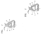
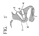
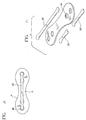
- Another aspect of the claimed invention includes devices having multi-components. Multi-component dilators essentially comprise a base, an over-the-bridge component, and a resilient member. The resilient member may be removable. FIG. 2 is an illustration of a multi-component dilator comprising a
base 1, an over-the-bridge component 2, and a removableresilient member 4. Thebase 1 includes acoupler 6 for receiving anend 5 ofresilient member 4. Another similar embodiment is set forth at FIG. 5. - The
coupler 6 for receiving anend 5 of theresilient member 4 can be selected from, for example, a pocket, pouch, strap, tie, hook and loop, etc. Theresilient member 4 may be selected from, for example, plastic, wire, elastic pieces, springs of various materials including shape memory materials, splines, or any other components that produce the desired dilating forces. - In a multi-component embodiment having a removable resilient member, the removable resilient member can be coupled with the base before or after application of the device to the nose. To illustrate use, an adhesive, pocketed, non-dilating base can be applied to the nose and a removable resilient member then placed within pockets of the base on either side of the nose. Once placed into the pockets and forced over the nose from a planar state, the resilient member tends to return to a planar state thereby producing dilating lift forces.
- In another embodiment, the resilient member, such as a multi-directional resilient member, can be used to produce tension forces that run, for example, parallel to the bridge of the nose in addition to lifting forces. To illustrate, FIGS. 1 and 3 show some devices comprising a base I having a plurality of
couplers 6 for receiving a removableresilient member 4 having a plurality ofends 5. This multi-directional arrangement increases the effectiveness of the dilator by providing both outwardly lifting forces as the resilient member tends to return to a planar state and tension forces to stretch the tissue in a direction parallel to the bridge of the nose. - The tension forces of multi-component devices may or may not be directed along an axis running parallel with the bridge of the nose. This arrangement provides a tension force or stretching of the skin in a direction perpendicular to the bridge of the nose as opposed to tension forces running parallel to the bridge of the nose.
- Other multi-component embodiments are shown in FIGs. 4, 6-8, 10-13 each comprising various features.
- FIG. 4. illustrates a multi-component embodiment comprising a removable
resilient member 4 having a graspingmember 4c. The graspingmember 4c can be selected from, for example, a rim, ridge, wedge, protrusion, notch, cutout, groove, or any other structure or device which allows a user to more easily grasp or handle aresilient member 4. - In another embodiment, as shown in FIG. 6, an arrangement may comprise a
base 1, an over-the-bridge component 2, and anelastic member 8 such as anelastic band 8a, connected to asecuring element 36 on each side of the nose. The dilation forces in this arrangement run across the bridge of the nose. As theelastic band 8a tends to return to its original position, theelastic band 8a presses against an over-the-bridge component 2. The force against the over-the-bridge component 2 causes the over-the-bridge component 2 to straighten thereby providing lifting dilation. - FIGs. 10 and 11 disclose arrangements similar to FIG. 6 having lower profiles to provide some users with more comfort. Of course, the use or application of multiple devices according to the present embodiments may be utilized. Another embodiment, as shown in FIG. 9 , comprises a
base 1 having an over-the-nose component 2, anelastic band 8a, and a plurality of securing elements 31. This arrangement also includes avoid 38 configured at or near the center of the dilator device. Thevoid 38 separates dilating forces to also provide some users with greater comfort. - A multi-component device can additionally provide selective incremental adjustment. The illustration in FIG. 7 discloses one embodiment having a
base 1, an over-the-bridge component 2, asecuring element 36, anelastic band 8a, and a plurality of incrementally spacedadjusters 10. Theadjusters 10 may include, for example, hooks, notches, protrusion, grooves, etc. Theadjuster 10 can be integral with thebase 1 or over-the-bridge component 2 or be a separate component that fixes to thebase 1 or over-the-bridge component 2. - To illustrate, as the
elastic band 8a is selectively positioned on theadjusters 10, the dilating force correspondingly adjusts. For example, placing theelastic member 8a higher on theadjusters 10 of the over-the-bridge component 2 shown in FIG. 7 creates a stronger dilating force. The illustrated position shown in FIG. 9 provides for the least dilating force. FIG. 8 discloses another adjuster arrangement. This embodiment provides for a triangular arrangement ofelastic bands 8a lessening the potential of pinching and increasing some user's comfort. - FIGs. 12 and 13 are all examples of multi-component dilator embodiments having various features as described earlier. The arrangements illustrated in FIGs. 12 and 13 provide for dilation lift to a larger area of skin on either side of the nose.
- FIGs. 14 and 15 depict an embodiment including a
base member 1, having an over-the-bridge portion 2 and having a series ofapertures 45 disposed along a longitudinal axis of thebase member 1 so that aresilient body member 25 may be releasably coupled to, and received by, theapertures 45. In this embodiment, theresilient body member 25 may be sized to fit in any two of saidapertures 45 thereby providing an adjustable magnitude of lifting force to thebase member 1. The ends ofresilient body member 25 may be formed to provide a friction fit to theapertures 45 or may be provided with adhesive material to promote the mechanical coupling therebetween. In this embodiment several different attachment mechanisms and materials may be utilized to create the desired dilation. For example,many ports 45 may be provided in thebody 1 of the dilator to receive one or more elongate members. As depicted in FIG. 15, a firstupper member 25 may have resilient properties (i.e., sustain a restoring force when bent or deformed from an original state) and may be directly coupled to any twoports 45 formed in thebody 1 of the dilator. Themember 25 may be one of a set of different members that each provide a different magnitude restoring force so that a user may select an appropriate magnitude of lifting force as desired by the user. In addition, one ormore addition members 25',25" may be coupled to thebody 1 or may be affixed or formed to receive the elongatefirst member 25 through theports 45. Theadditional members 25',25" may be formed of a material different than the material offirst member 25. The additional members may be formed of an elastic material and/or an adhesive material. As noted, these additional members may have a selected resilient (or elastic) force due to their chosen material composition, their length and the location at which they couple to thebody 1. Theadditional members 25',25" may have portions formed to receive and retain the ends of thefirst member 25, such a socket to receive a corresponding ball portion of thefirst member 25, and the like. - Other embodiments of a tissue dilator may have a dual set or more
resilient body members 25 with fastened with, for example, micro hook and loop type material on opposing sides of the body members so that they mechanically couple together and thus provide additional lifting force when combined. The base member of such a device also may be covered with a complementary layer of such micro hook and loop material to retain the first resilient body member to the exterior of the base member. A related embodiment having a single resilient member coupled to an elastic member of similar dimension may also be provided according to this embodiment. An adhesive layer of material is preferably provided on the base member on the side opposite to the resilient body members to promote adhesion to a local tissue area and an additional layer of adhesive. In these and other alternative embodiments of the present invention, the adhesive layer or portion that typically (and preferably) adheres the dilator to the local tissue region may be configured to be re-usable. In these embodiments, a pad member may slideably engage one or more resilient members so that during use the combination is retained in place. When the dilator device is removed by a user, the pad members may be manually removed and another substituted when the user is ready to apply another dilator device. The pad member may be adhered with a releasable adhesive, may be connected with a friction fit coupling, may be attached with a screw or threaded shank and the like. The net benefit to the user relates in part to the fact that once the user locates a resilient member having a magnitude of restoring force desired by the user, that same resilient member may be used on at least several different occasions with the same results. These embodiments allow for fabrication and use of a relatively expensive, customized resilient member fabricated for a single user or a group of users who desire a certain magnitude of force or a certain size of resilient member (and in most embodiments dilator device) that best promotes respiration for said user. - Other related embodiments relate to those just described , may have each end of a single resilient body member disposed in a set of pockets formed at each end of the base member. These pockets may be adhered, or heat sealed, laminated, connected with hook and loop fasteners and the like. This embodiment allows a user to install a variety of different resilient body members to provide differing levels of lifting force and/or having different physical dimensions to promote dilation of a local tissue region. Each one of said pockets may be retained with an adhesive or one side adhered and another fastened with micro hook and loop type fastener material and an
adhesive layer 3 provides a means to couple the device to a local tissue region on at least each end of thebody 1.
Claims (8)
- A tissue dilator device comprising:a base member (1) having a first attachment location and a second attachment location on a first major surface and an adhesive material on at least two portions of a second major surface opposite the first major surface; and,a resilient member(4) mechanically coupled to the first attachment location and the second attachment location to provide dilation forces, wherein the resilient member is selectively removable from the first attachment location and the second attachment location.
- A dilator device of claim 1, wherein the first attachment location and the second attachment location are defined by pockets (6) formed in the base member (1).
- A dilator device of claim 2 wherein the resilient member (4) is an elongated element having opposed ends (5) which are received into the pockets (6).
- A dilator device of claim 1, wherein the resilient member (4) is selected from among a group of different resilient members so that the magnitude of the dilator forces can be selectively adjusted.
- A dilator device of claim 1, wherein the first attachment location and the second attachment location are defined by apertures (45) in the base member (1).
- A dilator device of claim 1, wherein a series of apertures are defined and wherein the resilient member may be mechanically coupled to different pairs of the apertures to selectively adjust the magnitude of the dilation forces.
- A dilator device of claim 1, wherein the resilient member is at least a select one of the following: an elastic strap, a rubber band, a segment of metallic alloy, a composite material, a segment of plastic, or a segment of fabric.
- A dilator device of 7, wherein said resilient member couples to the base member using a select one of stitching, pocket portions, hooks, adhesive, thermal bonding or using a pair of hook and loop style fastener patches.
Applications Claiming Priority (7)
| Application Number | Priority Date | Filing Date | Title |
|---|---|---|---|
| US21502400P | 2000-06-29 | 2000-06-29 | |
| US21499500P | 2000-06-29 | 2000-06-29 | |
| US215024P | 2000-06-29 | ||
| US214995P | 2000-06-29 | ||
| US22110800P | 2000-07-27 | 2000-07-27 | |
| US221108P | 2000-07-27 | ||
| PCT/US2001/020957 WO2002005734A2 (en) | 2000-06-29 | 2001-06-29 | Tissue dilator devices, methods of fabrication of tissue dilators, and methods of use for tissue dilators |
Publications (2)
| Publication Number | Publication Date |
|---|---|
| EP1299056A2 EP1299056A2 (en) | 2003-04-09 |
| EP1299056B1 true EP1299056B1 (en) | 2006-03-15 |
Family
ID=27396061
Family Applications (1)
| Application Number | Title | Priority Date | Filing Date |
|---|---|---|---|
| EP01950765A Expired - Lifetime EP1299056B1 (en) | 2000-06-29 | 2001-06-29 | Nasal dilator |
Country Status (7)
| Country | Link |
|---|---|
| US (1) | US6631714B2 (en) |
| EP (1) | EP1299056B1 (en) |
| AT (1) | ATE320232T1 (en) |
| AU (1) | AU2001271728A1 (en) |
| DE (1) | DE60117991T2 (en) |
| ES (1) | ES2260248T3 (en) |
| WO (1) | WO2002005734A2 (en) |
Cited By (4)
| Publication number | Priority date | Publication date | Assignee | Title |
|---|---|---|---|---|
| USD662203S1 (en) | 2006-08-30 | 2012-06-19 | Smithkline Beecham Corporation | Nasal dilator |
| US8834511B2 (en) | 2006-10-23 | 2014-09-16 | GlaxoSmithKline, LLC | External nasal dilator and methods of manufacture |
| USD739015S1 (en) | 2014-03-05 | 2015-09-15 | Medline Industries, Inc. | Nasal dilator |
| USD741998S1 (en) | 2014-04-17 | 2015-10-27 | Medline Industries, Inc. | Nasal dilator |
Families Citing this family (47)
| Publication number | Priority date | Publication date | Assignee | Title |
|---|---|---|---|---|
| US20060029653A1 (en) | 1997-01-29 | 2006-02-09 | Cronk Peter J | Therapeutic delivery system |
| US6694970B2 (en) * | 2002-01-08 | 2004-02-24 | Omnitek Partners Llc | Adhesive strip for opening nasal passages |
| US20050274387A1 (en) * | 2004-06-10 | 2005-12-15 | John Macken | Method and apparatus for treatment of snoring and sleep apnea |
| US20070221231A1 (en) * | 2004-06-10 | 2007-09-27 | Macken John A | Method and apparatus for treatment of snoring and sleep apnea |
| FR2872054B1 (en) | 2004-06-28 | 2007-03-02 | Alexandre Yazdi | NASAL DILATOR |
| US20060266367A1 (en) * | 2005-05-27 | 2006-11-30 | Alisa Noce | Nasal dilator |
| US20060266360A1 (en) * | 2005-05-27 | 2006-11-30 | Alisa Noce | Nasal dilator |
| US7947076B2 (en) * | 2005-06-03 | 2011-05-24 | Medtronic Xomed, Inc. | Nasal valve treatment method and apparatus |
| US7798141B2 (en) * | 2005-08-05 | 2010-09-21 | Veeder Matthew P | Manually adjustable nasal cavity dilator |
| RU2419464C2 (en) * | 2005-11-07 | 2011-05-27 | Си Эн Эс, Инк. | Element with deferred spring load for nasal expanders for nasal dilators |
| EP1797846A1 (en) * | 2005-12-13 | 2007-06-20 | John A. Macken | Method and apparatus for treatment of snoring and sleep apnea |
| USD753294S1 (en) | 2006-04-27 | 2016-04-05 | Innovative Medical Equipment, Llc | Nasal dilator |
| US8047201B2 (en) * | 2006-04-27 | 2011-11-01 | Innovation Alley Design, Llc | Nasal dilator |
| US8858587B2 (en) * | 2008-03-12 | 2014-10-14 | Corbett Lair, Inc. | Nasal dilator and method of manufacture |
| US8584671B2 (en) * | 2007-02-06 | 2013-11-19 | Corbett-Lair Inc. | Economical nasal dilator and method of manufacture |
| US20170151084A9 (en) * | 2007-02-06 | 2017-06-01 | Joseph V. Ierulli | Economical Nasal Dilator and Method of Manufacture |
| US20120209313A1 (en) * | 2007-04-21 | 2012-08-16 | Joseph Vincent Ierulli | Nasal Dilator With Means To Direct Resilient Properties |
| US8043343B2 (en) * | 2007-06-28 | 2011-10-25 | Zimmer Spine, Inc. | Stabilization system and method |
| US8342173B2 (en) * | 2007-07-19 | 2013-01-01 | Silver Eagle Labs Inc. | Nasal dilator with cushion layer and variable spring rate |
| ITMI20072156A1 (en) * | 2007-11-13 | 2009-05-14 | Biofarmitalia Spa | NASAL PATCH |
| US8834512B1 (en) * | 2007-12-12 | 2014-09-16 | International Patent Development Group, Llc | Nasal dilator comprising joined legs with end pads and air passages |
| US20100042134A1 (en) * | 2008-04-18 | 2010-02-18 | Abraham Wien | Nostril dilator |
| USD659245S1 (en) * | 2008-04-19 | 2012-05-08 | Ierulli Joseph V | Nasal dilator |
| US8246647B2 (en) * | 2008-11-14 | 2012-08-21 | Abraham Wien | Nostril dilator |
| US20110000483A1 (en) * | 2009-05-01 | 2011-01-06 | Matthias Joseph A | External nasal dilator |
| US9095674B2 (en) * | 2009-08-10 | 2015-08-04 | Dean M. Toriumi | Nose clip |
| US9308114B2 (en) * | 2009-12-18 | 2016-04-12 | Andrew Lehman | Adjustable nasal passage expander |
| USD672872S1 (en) | 2009-12-23 | 2012-12-18 | GlaxoSmithKline, LLC | Nasal dilator |
| AR079672A1 (en) | 2009-12-23 | 2012-02-08 | Glaxosmithkline Llc | IMPROVED EXTERNAL NASAL DILATOR |
| WO2012003435A2 (en) * | 2010-07-02 | 2012-01-05 | Liberman Distributing And Manufacturing Co. | Method and structure for nasal dilator |
| US20120067345A1 (en) * | 2010-09-22 | 2012-03-22 | Eyal Shilon | Nasal Dilation Method And Device |
| US10603221B1 (en) * | 2011-01-06 | 2020-03-31 | Van J. Kantor | Noninvasive device and method for neck lift |
| US20120203268A1 (en) * | 2011-02-07 | 2012-08-09 | Lin Chien | Wrinkle remover |
| KR101209243B1 (en) | 2011-04-15 | 2012-12-06 | 이용행 | Forehead lift device for forehead lift procedure |
| US9427945B2 (en) | 2011-12-30 | 2016-08-30 | Liberman Distributing And Manufacturing Co. | Extendable self-supporting material composites and manufacture thereof |
| US20130190807A1 (en) * | 2012-01-23 | 2013-07-25 | Allen Richard Andis | Method for reusable nasal passage dilator |
| USD789531S1 (en) * | 2012-10-01 | 2017-06-13 | Corbett-Lair Inc. | Double band nasal dilator |
| US8801751B2 (en) * | 2012-10-26 | 2014-08-12 | Heal Medical Llc | Nasal splint |
| USD722161S1 (en) | 2013-02-15 | 2015-02-03 | L. Perrigo Company | Nasal dilator |
| USD722162S1 (en) | 2013-02-15 | 2015-02-03 | L. Perrigo Company | Nasal dilator |
| USD706926S1 (en) | 2013-02-15 | 2014-06-10 | L. Perrigo Company | Nasal dilator |
| USD706925S1 (en) | 2013-02-15 | 2014-06-10 | L. Perrigo Company | Nasal dilator |
| USD743565S1 (en) | 2013-06-17 | 2015-11-17 | Ranir, Llc | Nasal dilator |
| US20160015154A1 (en) | 2014-07-18 | 2016-01-21 | Matthew P. Veeder | Use of adhesive patch and tension strap to reduce wrinkles in skin |
| US20200129682A1 (en) * | 2018-10-31 | 2020-04-30 | Mitsui Chemicals, Inc. | Supporter for body |
| USD903114S1 (en) * | 2019-04-06 | 2020-11-24 | Corbett Lair, Inc. | Nasal dilator |
| EP3718516A3 (en) * | 2019-04-06 | 2020-12-16 | Joseph Ierulli | Nasal dilators with improved breathability |
Family Cites Families (15)
| Publication number | Priority date | Publication date | Assignee | Title |
|---|---|---|---|---|
| US1292083A (en) * | 1918-02-04 | 1919-01-21 | William F Sawyer | Nostril-dilator. |
| US5549103A (en) | 1991-06-10 | 1996-08-27 | Creative Integration & Design, Inc. | Nasal dilator having an adhesive void to allow relative movement |
| US5476091A (en) | 1991-06-10 | 1995-12-19 | Creative Integration & Design, Inc. | Dilator for anatomical outer wall tissues which is adhesively mounted |
| US5533499A (en) | 1991-06-10 | 1996-07-09 | Creative Integration & Design, Inc. | Nasal dilator |
| US5653224A (en) | 1991-06-10 | 1997-08-05 | Creative Integration & Design, Inc. | Nasal dilator with areas of adhesive engagement of varying strength |
| US5391182A (en) | 1993-08-03 | 1995-02-21 | Origin Medsystems, Inc. | Apparatus and method for closing puncture wounds |
| US5546929A (en) | 1995-07-07 | 1996-08-20 | Muchin Jerome D | Nasal dilator |
| US5553605A (en) | 1995-08-31 | 1996-09-10 | Muchin Jerome D | Transparent external nasal dilator |
| US5718224A (en) * | 1996-08-16 | 1998-02-17 | Muchin; Jerome D. | Transparent nasal dilator |
| US5816241A (en) * | 1995-09-29 | 1998-10-06 | Cook; Lori Irene | Coiled nasal dilator |
| US5611333A (en) | 1995-12-15 | 1997-03-18 | Creative Integration & Design, Inc. | Dilator with peel force reducing structure |
| US6470883B1 (en) | 1996-05-10 | 2002-10-29 | Wallace J. Beaudry | Nasal epidermal lifting mechanism |
| US6352548B1 (en) * | 1999-08-23 | 2002-03-05 | Winease Llc | Nasal support device for animals and method |
| US6453901B1 (en) * | 1999-07-19 | 2002-09-24 | Joseph V. Ierulli | Nasal dilator and method of making the same |
| US6375667B1 (en) * | 1999-09-23 | 2002-04-23 | North American Financial Corp | Nasal dilator |
-
2001
- 2001-06-29 AU AU2001271728A patent/AU2001271728A1/en not_active Abandoned
- 2001-06-29 WO PCT/US2001/020957 patent/WO2002005734A2/en active IP Right Grant
- 2001-06-29 US US09/896,213 patent/US6631714B2/en not_active Expired - Lifetime
- 2001-06-29 ES ES01950765T patent/ES2260248T3/en not_active Expired - Lifetime
- 2001-06-29 EP EP01950765A patent/EP1299056B1/en not_active Expired - Lifetime
- 2001-06-29 DE DE60117991T patent/DE60117991T2/en not_active Expired - Lifetime
- 2001-06-29 AT AT01950765T patent/ATE320232T1/en not_active IP Right Cessation
Cited By (6)
| Publication number | Priority date | Publication date | Assignee | Title |
|---|---|---|---|---|
| USD662203S1 (en) | 2006-08-30 | 2012-06-19 | Smithkline Beecham Corporation | Nasal dilator |
| US8834514B2 (en) | 2006-08-30 | 2014-09-16 | Xennovate Medical Llc | Resilient band medical device |
| US8834511B2 (en) | 2006-10-23 | 2014-09-16 | GlaxoSmithKline, LLC | External nasal dilator and methods of manufacture |
| US9901479B2 (en) | 2006-10-23 | 2018-02-27 | GlaxoSmithKline, LLC | External nasal dilator and methods |
| USD739015S1 (en) | 2014-03-05 | 2015-09-15 | Medline Industries, Inc. | Nasal dilator |
| USD741998S1 (en) | 2014-04-17 | 2015-10-27 | Medline Industries, Inc. | Nasal dilator |
Also Published As
| Publication number | Publication date |
|---|---|
| US20020000227A1 (en) | 2002-01-03 |
| ATE320232T1 (en) | 2006-04-15 |
| DE60117991T2 (en) | 2006-08-17 |
| WO2002005734A2 (en) | 2002-01-24 |
| ES2260248T3 (en) | 2006-11-01 |
| DE60117991D1 (en) | 2006-05-11 |
| US6631714B2 (en) | 2003-10-14 |
| WO2002005734A3 (en) | 2002-06-20 |
| AU2001271728A1 (en) | 2002-01-30 |
| EP1299056A2 (en) | 2003-04-09 |
Similar Documents
| Publication | Publication Date | Title |
|---|---|---|
| EP1299056B1 (en) | Nasal dilator | |
| US6065470A (en) | Nostril dilator | |
| US6478023B1 (en) | Skin stabilization and nasal dilator system | |
| US8616198B2 (en) | Nasal dilator | |
| JP3892484B2 (en) | Improvements related to respiratory assistance | |
| AU752813B2 (en) | Custom fitted orthotic device | |
| US7329231B2 (en) | Dome-shaped back brace | |
| US20110000483A1 (en) | External nasal dilator | |
| US20050247317A1 (en) | Nasal strip with variable spring rate | |
| US20090020115A1 (en) | Nasal dilator with cushion layer and variable spring rate | |
| PL184662B1 (en) | Method of reducing scraping force produced by retractors | |
| US4995383A (en) | Corrective posture device | |
| US20140121696A1 (en) | Nasal splint | |
| US20060129076A1 (en) | Broken collar bone fixing band | |
| US20090025715A1 (en) | Breathing Assistance Device | |
| US20050039423A1 (en) | Girth strap device | |
| CA2217946A1 (en) | Nostril dilator | |
| CN216221919U (en) | Upper torso support device | |
| CN214415008U (en) | Splint fastener for fracture | |
| CN217119301U (en) | Bionic bone curve elastic support waist protection device | |
| US20240139019A1 (en) | External Nasal Dilator | |
| GB2330079A (en) | Nasal breathing aid | |
| KR20190002365U (en) | Medical armrest | |
| AU2002322200A1 (en) | Girth strap device | |
| DE20319673U1 (en) | Fixing strip for endotracheal tube consists of first upholstered strip bearing an adhesive on both sides and second center section with point-applied adhesive |
Legal Events
| Date | Code | Title | Description |
|---|---|---|---|
| PUAI | Public reference made under article 153(3) epc to a published international application that has entered the european phase |
Free format text: ORIGINAL CODE: 0009012 |
|
| 17P | Request for examination filed |
Effective date: 20030129 |
|
| AK | Designated contracting states |
Kind code of ref document: A2 Designated state(s): AT BE CH CY DE DK ES FI FR GB GR IE IT LI LU MC NL PT SE TR |
|
| AX | Request for extension of the european patent |
Extension state: AL LT LV MK RO SI |
|
| 17Q | First examination report despatched |
Effective date: 20041021 |
|
| GRAP | Despatch of communication of intention to grant a patent |
Free format text: ORIGINAL CODE: EPIDOSNIGR1 |
|
| GRAS | Grant fee paid |
Free format text: ORIGINAL CODE: EPIDOSNIGR3 |
|
| GRAA | (expected) grant |
Free format text: ORIGINAL CODE: 0009210 |
|
| AK | Designated contracting states |
Kind code of ref document: B1 Designated state(s): AT BE CH CY DE DK ES FI FR GB GR IE IT LI LU MC NL PT SE TR |
|
| PG25 | Lapsed in a contracting state [announced via postgrant information from national office to epo] |
Ref country code: LI Free format text: LAPSE BECAUSE OF FAILURE TO SUBMIT A TRANSLATION OF THE DESCRIPTION OR TO PAY THE FEE WITHIN THE PRESCRIBED TIME-LIMIT Effective date: 20060315 Ref country code: BE Free format text: LAPSE BECAUSE OF FAILURE TO SUBMIT A TRANSLATION OF THE DESCRIPTION OR TO PAY THE FEE WITHIN THE PRESCRIBED TIME-LIMIT Effective date: 20060315 Ref country code: AT Free format text: LAPSE BECAUSE OF FAILURE TO SUBMIT A TRANSLATION OF THE DESCRIPTION OR TO PAY THE FEE WITHIN THE PRESCRIBED TIME-LIMIT Effective date: 20060315 Ref country code: CH Free format text: LAPSE BECAUSE OF FAILURE TO SUBMIT A TRANSLATION OF THE DESCRIPTION OR TO PAY THE FEE WITHIN THE PRESCRIBED TIME-LIMIT Effective date: 20060315 Ref country code: FI Free format text: LAPSE BECAUSE OF FAILURE TO SUBMIT A TRANSLATION OF THE DESCRIPTION OR TO PAY THE FEE WITHIN THE PRESCRIBED TIME-LIMIT Effective date: 20060315 |
|
| REG | Reference to a national code |
Ref country code: GB Ref legal event code: FG4D Ref country code: CH Ref legal event code: EP |
|
| REG | Reference to a national code |
Ref country code: IE Ref legal event code: FG4D |
|
| REF | Corresponds to: |
Ref document number: 60117991 Country of ref document: DE Date of ref document: 20060511 Kind code of ref document: P |
|
| PG25 | Lapsed in a contracting state [announced via postgrant information from national office to epo] |
Ref country code: SE Free format text: LAPSE BECAUSE OF FAILURE TO SUBMIT A TRANSLATION OF THE DESCRIPTION OR TO PAY THE FEE WITHIN THE PRESCRIBED TIME-LIMIT Effective date: 20060615 Ref country code: DK Free format text: LAPSE BECAUSE OF FAILURE TO SUBMIT A TRANSLATION OF THE DESCRIPTION OR TO PAY THE FEE WITHIN THE PRESCRIBED TIME-LIMIT Effective date: 20060615 |
|
| PG25 | Lapsed in a contracting state [announced via postgrant information from national office to epo] |
Ref country code: IE Free format text: LAPSE BECAUSE OF NON-PAYMENT OF DUE FEES Effective date: 20060629 |
|
| PG25 | Lapsed in a contracting state [announced via postgrant information from national office to epo] |
Ref country code: MC Free format text: LAPSE BECAUSE OF NON-PAYMENT OF DUE FEES Effective date: 20060630 |
|
| PG25 | Lapsed in a contracting state [announced via postgrant information from national office to epo] |
Ref country code: PT Free format text: LAPSE BECAUSE OF FAILURE TO SUBMIT A TRANSLATION OF THE DESCRIPTION OR TO PAY THE FEE WITHIN THE PRESCRIBED TIME-LIMIT Effective date: 20060816 |
|
| REG | Reference to a national code |
Ref country code: CH Ref legal event code: PL |
|
| ET | Fr: translation filed | ||
| REG | Reference to a national code |
Ref country code: ES Ref legal event code: FG2A Ref document number: 2260248 Country of ref document: ES Kind code of ref document: T3 |
|
| PLBE | No opposition filed within time limit |
Free format text: ORIGINAL CODE: 0009261 |
|
| STAA | Information on the status of an ep patent application or granted ep patent |
Free format text: STATUS: NO OPPOSITION FILED WITHIN TIME LIMIT |
|
| 26N | No opposition filed |
Effective date: 20061218 |
|
| PG25 | Lapsed in a contracting state [announced via postgrant information from national office to epo] |
Ref country code: GR Free format text: LAPSE BECAUSE OF FAILURE TO SUBMIT A TRANSLATION OF THE DESCRIPTION OR TO PAY THE FEE WITHIN THE PRESCRIBED TIME-LIMIT Effective date: 20060616 |
|
| PG25 | Lapsed in a contracting state [announced via postgrant information from national office to epo] |
Ref country code: TR Free format text: LAPSE BECAUSE OF FAILURE TO SUBMIT A TRANSLATION OF THE DESCRIPTION OR TO PAY THE FEE WITHIN THE PRESCRIBED TIME-LIMIT Effective date: 20060315 Ref country code: LU Free format text: LAPSE BECAUSE OF NON-PAYMENT OF DUE FEES Effective date: 20060629 |
|
| PG25 | Lapsed in a contracting state [announced via postgrant information from national office to epo] |
Ref country code: CY Free format text: LAPSE BECAUSE OF FAILURE TO SUBMIT A TRANSLATION OF THE DESCRIPTION OR TO PAY THE FEE WITHIN THE PRESCRIBED TIME-LIMIT Effective date: 20060315 |
|
| REG | Reference to a national code |
Ref country code: FR Ref legal event code: PLFP Year of fee payment: 16 |
|
| REG | Reference to a national code |
Ref country code: FR Ref legal event code: PLFP Year of fee payment: 17 |
|
| PGFP | Annual fee paid to national office [announced via postgrant information from national office to epo] |
Ref country code: GB Payment date: 20170526 Year of fee payment: 17 |
|
| PGFP | Annual fee paid to national office [announced via postgrant information from national office to epo] |
Ref country code: NL Payment date: 20170613 Year of fee payment: 17 |
|
| PGFP | Annual fee paid to national office [announced via postgrant information from national office to epo] |
Ref country code: ES Payment date: 20170705 Year of fee payment: 17 |
|
| REG | Reference to a national code |
Ref country code: FR Ref legal event code: PLFP Year of fee payment: 18 |
|
| REG | Reference to a national code |
Ref country code: NL Ref legal event code: MM Effective date: 20180701 |
|
| GBPC | Gb: european patent ceased through non-payment of renewal fee |
Effective date: 20180629 |
|
| PG25 | Lapsed in a contracting state [announced via postgrant information from national office to epo] |
Ref country code: NL Free format text: LAPSE BECAUSE OF NON-PAYMENT OF DUE FEES Effective date: 20180701 |
|
| PG25 | Lapsed in a contracting state [announced via postgrant information from national office to epo] |
Ref country code: GB Free format text: LAPSE BECAUSE OF NON-PAYMENT OF DUE FEES Effective date: 20180629 |
|
| REG | Reference to a national code |
Ref country code: ES Ref legal event code: FD2A Effective date: 20190916 |
|
| PG25 | Lapsed in a contracting state [announced via postgrant information from national office to epo] |
Ref country code: ES Free format text: LAPSE BECAUSE OF NON-PAYMENT OF DUE FEES Effective date: 20180630 |
|
| REG | Reference to a national code |
Ref country code: DE Ref legal event code: R081 Ref document number: 60117991 Country of ref document: DE Owner name: GLAXOSMITHKLINE CONSUMER HEALTHCARE (UK) IP LI, GB Free format text: FORMER OWNER: CNS, INC., EDEN PRAIRIE, MINN., US Ref country code: DE Ref legal event code: R082 Ref document number: 60117991 Country of ref document: DE Representative=s name: BOEHMERT & BOEHMERT ANWALTSPARTNERSCHAFT MBB -, DE |
|
| PGFP | Annual fee paid to national office [announced via postgrant information from national office to epo] |
Ref country code: DE Payment date: 20200518 Year of fee payment: 20 Ref country code: FR Payment date: 20200520 Year of fee payment: 20 |
|
| PGFP | Annual fee paid to national office [announced via postgrant information from national office to epo] |
Ref country code: IT Payment date: 20200610 Year of fee payment: 20 |
|
| REG | Reference to a national code |
Ref country code: DE Ref legal event code: R071 Ref document number: 60117991 Country of ref document: DE |