EP1301032A1 - Camera, camera connecting device, and camera system - Google Patents
Camera, camera connecting device, and camera system Download PDFInfo
- Publication number
- EP1301032A1 EP1301032A1 EP02080180A EP02080180A EP1301032A1 EP 1301032 A1 EP1301032 A1 EP 1301032A1 EP 02080180 A EP02080180 A EP 02080180A EP 02080180 A EP02080180 A EP 02080180A EP 1301032 A1 EP1301032 A1 EP 1301032A1
- Authority
- EP
- European Patent Office
- Prior art keywords
- camera
- release
- connecting device
- release button
- memory
- Prior art date
- Legal status (The legal status is an assumption and is not a legal conclusion. Google has not performed a legal analysis and makes no representation as to the accuracy of the status listed.)
- Granted
Links
Images


Classifications
-
- H—ELECTRICITY
- H04—ELECTRIC COMMUNICATION TECHNIQUE
- H04N—PICTORIAL COMMUNICATION, e.g. TELEVISION
- H04N1/00—Scanning, transmission or reproduction of documents or the like, e.g. facsimile transmission; Details thereof
- H04N1/00127—Connection or combination of a still picture apparatus with another apparatus, e.g. for storage, processing or transmission of still picture signals or of information associated with a still picture
- H04N1/00204—Connection or combination of a still picture apparatus with another apparatus, e.g. for storage, processing or transmission of still picture signals or of information associated with a still picture with a digital computer or a digital computer system, e.g. an internet server
- H04N1/00236—Connection or combination of a still picture apparatus with another apparatus, e.g. for storage, processing or transmission of still picture signals or of information associated with a still picture with a digital computer or a digital computer system, e.g. an internet server using an image reading or reproducing device, e.g. a facsimile reader or printer, as a local input to or local output from a computer
- H04N1/00241—Connection or combination of a still picture apparatus with another apparatus, e.g. for storage, processing or transmission of still picture signals or of information associated with a still picture with a digital computer or a digital computer system, e.g. an internet server using an image reading or reproducing device, e.g. a facsimile reader or printer, as a local input to or local output from a computer using an image reading device as a local input to a computer
-
- H—ELECTRICITY
- H04—ELECTRIC COMMUNICATION TECHNIQUE
- H04N—PICTORIAL COMMUNICATION, e.g. TELEVISION
- H04N1/00—Scanning, transmission or reproduction of documents or the like, e.g. facsimile transmission; Details thereof
- H04N1/00127—Connection or combination of a still picture apparatus with another apparatus, e.g. for storage, processing or transmission of still picture signals or of information associated with a still picture
- H04N1/00204—Connection or combination of a still picture apparatus with another apparatus, e.g. for storage, processing or transmission of still picture signals or of information associated with a still picture with a digital computer or a digital computer system, e.g. an internet server
- H04N1/00236—Connection or combination of a still picture apparatus with another apparatus, e.g. for storage, processing or transmission of still picture signals or of information associated with a still picture with a digital computer or a digital computer system, e.g. an internet server using an image reading or reproducing device, e.g. a facsimile reader or printer, as a local input to or local output from a computer
-
- H—ELECTRICITY
- H04—ELECTRIC COMMUNICATION TECHNIQUE
- H04N—PICTORIAL COMMUNICATION, e.g. TELEVISION
- H04N1/00—Scanning, transmission or reproduction of documents or the like, e.g. facsimile transmission; Details thereof
- H04N1/21—Intermediate information storage
- H04N1/2104—Intermediate information storage for one or a few pictures
- H04N1/2112—Intermediate information storage for one or a few pictures using still video cameras
- H04N1/2137—Intermediate information storage for one or a few pictures using still video cameras with temporary storage before final recording, e.g. in a frame buffer
-
- H—ELECTRICITY
- H04—ELECTRIC COMMUNICATION TECHNIQUE
- H04N—PICTORIAL COMMUNICATION, e.g. TELEVISION
- H04N23/00—Cameras or camera modules comprising electronic image sensors; Control thereof
- H04N23/60—Control of cameras or camera modules
- H04N23/66—Remote control of cameras or camera parts, e.g. by remote control devices
-
- H—ELECTRICITY
- H04—ELECTRIC COMMUNICATION TECHNIQUE
- H04N—PICTORIAL COMMUNICATION, e.g. TELEVISION
- H04N1/00—Scanning, transmission or reproduction of documents or the like, e.g. facsimile transmission; Details thereof
- H04N1/00127—Connection or combination of a still picture apparatus with another apparatus, e.g. for storage, processing or transmission of still picture signals or of information associated with a still picture
- H04N1/00204—Connection or combination of a still picture apparatus with another apparatus, e.g. for storage, processing or transmission of still picture signals or of information associated with a still picture with a digital computer or a digital computer system, e.g. an internet server
-
- H—ELECTRICITY
- H04—ELECTRIC COMMUNICATION TECHNIQUE
- H04N—PICTORIAL COMMUNICATION, e.g. TELEVISION
- H04N2101/00—Still video cameras
-
- H—ELECTRICITY
- H04—ELECTRIC COMMUNICATION TECHNIQUE
- H04N—PICTORIAL COMMUNICATION, e.g. TELEVISION
- H04N2201/00—Indexing scheme relating to scanning, transmission or reproduction of documents or the like, and to details thereof
- H04N2201/0008—Connection or combination of a still picture apparatus with another apparatus
- H04N2201/0013—Arrangements for the control of the connected apparatus by the still picture apparatus
Definitions
- FIG. 7 A digital camera for digital recording is known such as shown in Fig. 7.
- reference numeral 710 represents a card-type digital camera
- reference numeral 720 represents a general personal computer (hereinafter called a PC).
- the internal structures thereof are shown in block in Fig. 7.
- PostMessage is a standard function of Windows API for sending a message to an application.
- Windows API is an application programming interface of Microsoft Windows (registered trademarks or trademark of Microsoft, Corporation). This message is not immediately processed by the application but is loaded in a message queue.
- Step S512 the still image is written in a clip board used as a system shared memory provided by OS such as Microsoft ® Windows ® 95.
- OS such as Microsoft ® Windows ® 95.
- the still image may be pasted to another application or the like.
- a user selects a desired function from the menu supplied by the application program so that the function of the release button 118 of the camera 110 can be set to one of saving a still image into a disk, saving a still image into a clip board, and not saving a still image.
Abstract
The release button of the camera may be used to have a desired function by providing a function selecting unit of application software.
Description
- The present invention relates to a camera used with removably being connected it to an external connecting device such as a personal computer, a personal digital assistant (PDA: information terminal equipment) and a word processor, and to a connecting device of such the camera and a camera system including such the camera and connecting device.
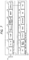
- A digital camera for digital recording is known such as shown in Fig. 7. In Fig. 7,
reference numeral 710 represents a card-type digital camera, andreference numeral 720 represents a general personal computer (hereinafter called a PC). The internal structures thereof are shown in block in Fig. 7. - In the structures shown in Fig. 7, a subject image passed through a lens 701 of an optical system is picked up by an image
pickup element CCD 711, subjected to predetermined processes such as CDS and AGC, and amplified to a predetermined level by a pre-amplifier 713. The analog image signal is then converted into a digital image signal by an A/D converter 714, processed by asignal processing circuit 715, and temporarily stored in amemory 716. - The above-described operations are controlled by a
controller 717 which also outputs an interrupt signal to aPC 720. Upon reception of this interrupt signal, PC 720 performs an interrupt routine. - PC 720 is generally constituted of a
CPU 721, amain memory 722, adisplay 723, amouse 724, akeyboard 725, an HDD 726, an FDD 727 and a local bus 728. - In such a conventional card-type digital camera system, the interrupt routine of
PC 720 copies an image in thememory 716 into themain memory 722 under the control ofCPU 721 of PC 720. This copied image is displayed on thedisplay 723 by an application program. If these operations are performed successively, a moving image can be displayed. If a space key of the keyboard is depressed during the display of a moving image, a still image can be saved in a clip board or in a disk medium such as a hard disk. - With such a conventional camera system of the type that a camera head unit and a camera card are interconnected by a cable, a still image can be picked up only by actuating a keyboard or mouse of a PC.
- The present invention has been made in order to solve the above problem and aims at providing a camera capable of picking up a still image by actuating a release switch of the camera, its connecting device and a camera system thereof.
- According to one aspect of the present invention, a camera is configured as in the following.
- (1) A camera removably connected to an external connecting device wherein the function of a release switch of the camera can be changed by the connecting device connected to the camera.
- (2) The camera described in (1), wherein the release switch is used to have a desired function, by the provision of selecting means in application software.
- (3) The camera described in (1), wherein there is provided a medium for storing a status of the release switch, the medium being changed as desired by selecting means provided in application software.
- (4) The camera described in (3), wherein the medium is a disk.
- (5) The camera described in (3), wherein the medium is a shared memory.
- (6) The camera described in (1), wherein an interrupt signal is sent to the connecting device upon the actuation of the release button, and in response to the interrupt signal, the connecting device processes an image signal picked up with the camera. According to another aspect of the present invention, a camera connecting device is configured as in the following.
- (7) A connecting device removable connected to a camera, comprising input means having the same function as a release switch of the camera.
- (8) A connecting device removable connected to a camera, comprising means for detecting whether the camera is equipped with a release switch. According to still another aspect of the present invention, a camera system is configured as in the following.
- (9) A camera system having a camera and a connecting device for removably connecting the camera, comprising means for detecting whether a camera with a release switch or a camera without a release switch is connected.
- (10) The system described in (9), the system is adapted to start up a photographing operation by the release switch of that camera, when the camera having the release switch is connected.
- (11) The system described in (9), wherein a display of the delecting means is changed according to whether the camera with the release switch or the camera without the release switch is connected.
-
- Other features of the present invention will become more apparent from the following detailed description of embodiments when read in conjunction with the accompanying drawings.
-
- Fig. 1 is a block diagram showing the structure of a camera system of this invention.
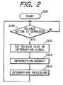
- Fig. 2 is a flow chart illustrating the operation of a camera side according to a first embodiment of the invention.
- Figs. 3A and 3B are flow charts illustrating the operation of a connecting device side according to the first embodiment of the invention.
- Fig. 4 is a flow chart illustrating the operation of a connecting device side according to a second embodiment of the invention.
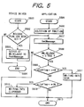
- Fig. 5 is a flow chart illustrating the operation of a connecting device side according to a third embodiment of the invention.
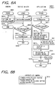
- Figs. 6A and 6B are flow charts illustrating the operation of a connecting device side according to a fourth embodiment of the invention.
- Fig. 7 is a block diagram showing the structure of a conventional camera system.
-
- Fig. 1 is a block diagram showing the structure of a camera system of the invention, the structure being basically the same as that of the system shown in Fig. 7.
- In Fig. 1,
reference numeral 101 represents a lens of an optical system for focussing a subject image, andreference numeral 110 represents a card-type digital camera capable of being removably mounted on a card slot of aPC 120 which is an external connecting device. Thecamera 110 has an electrical circuit for interconnecting the optical system andPC 120 together. - In the card-type
digital camera 110,reference numeral 111 represents an image pickup CCD for converting a subject image (optical image) passed through thelens 101 of the optical system into an electrical signal.Reference numeral 112 represents a correction circuit for performing predetermined signal processing such as CDS and AGC.Reference numeral 113 represents a pre-amplifier for amplifying the signal corrected by thecorrection circuit 112.Reference numeral 114 represents an A/D converter for converting the amplified analog image signal into a digital image signal.Reference numeral 115 represents a signal processing circuit for performing predetermined digital signal processing.Reference numeral 116 represents a writable memory, reference numeral 117 represents a controller for controlling the whole operation of the camera system, andreference numeral 118 represents a release button (switch). - In PC 120,
reference numeral 121 represents a CPU for controlling the whole operation of PC,reference numeral 122 represents a main memory,reference numeral 123 represents a display for displaying various information,reference numerals reference numeral 126 represents an HDD, andreference numeral 127 represents an FDD. These elements are connected via a local bus 128 to the controller 117. - The external connecting device such as PC 120 may be a PDA, a word processor or the like. In this embodiment, PC is used by way of example.
- Next, the operation of the camera system of the first embodiment will be described with reference to Figs. 2, 3A and 3B.
- Fig. 2 is a flow chart illustrating the operation of release means on the camera side. After a power of the
camera 110 is turned on at Step S201, it is checked at Step S202 whether therelease button 118 is depressed. If depressed, the flow advances to Step S203, whereas if not, the flow remains at Step S202 to monitor a depression of therelease button 118. - At Step S203 the controller 117 sets a release flag to an interrupt signal. Next at Step S204 an interrupt request is issued to the PC side. At Step S205 an interrupt process is performed on the PC side to thereafter terminate this process.
- Figs. 3A and 3B are flow charts illustrating the operation to be performed on the PC (connecting device) side, this operation corresponding to the interrupt process at S205 on the PC side shown in Fig. 2. Fig. 3A illustrates the processes of device driver software and application software, and Fig. 3B illustrates a freeze process.
- When the interrupt process starts at Step S301, it is checked at Step S302 whether the release flag is set. If set, the flow advances to Step S303, whereas if not, the flow advances to Step S304 whereat the release interrupt process of device driver software is terminated.
- At Step S303, a message "WM_RELEASE" is output (PostMessage) to the application software. PostMessage is a standard function of Windows API for sending a message to an application. Windows API is an application programming interface of Microsoft Windows (registered trademarks or trademark of Microsoft, Corporation). This message is not immediately processed by the application but is loaded in a message queue.
- Therefore, the message from the driver software does not synchronize with a freeze process (to be later described) of the application software. This message may be made synchronous. However, in this case, a message notified to each application is assigned uniquely so that the application which does not know this message cannot run.
- When the application program starts at Step S305, the message is picked up (GetMessage) from the message queue at Step S306. At Step S307 it is checked whether WM_RELEASE==TRUE. If true, the flow advances to Step S308, whereas if not, this release interrupt process is terminated at Step S309.
- At Step S308 the freeze process is performed to terminate this release interrupt process at Step S309.
- The freeze process starts at Step S310. Before this operation, the
display 123 ofPC 120 is in a preview state. In this preview state, a moving image is continuously displayed on thedisplay 123 by copying image data from thememory 116 of the card-type camera 110 to themain memory 122 ofPC 120. In this preview state, themain memory 122 ofPC 120 is used temporarily and when new image data is copied, the contents of themain memory 122 are overwritten. - At Step S311 image data in the
memory 116 of thecamera 110 is copied to themain memory 122 ofPC 120. This main memory is a semiconductor storage medium such as a DRAM, and image data in themain memory 122 may be copied later to a disk in the form of image file. Next at Step S312 the image data in themain memory 122 ofPC 120 is displayed on thedisplay 123 as a still image to terminate this freeze process at Step S313. - The second embodiment of this invention will be described. In this embodiment, the application software is changed as shown in Fig. 4 in order to use the
release button 118 of thecamera 110 for the actuation of the freeze (release) process. - Fig. 4 is a flow chart illustrating an interrupt process on the PC side with device driver software, application software and an event from an input device.
- When the interrupt process starts at Step S401, it is checked at Step S402 whether the release flag is set. If set, the flow advances to Step S403, whereas if not, the flow advances to Step S404 whereat the release interrupt process of device driver software is terminated.
- At Step S403, a message "WM_RELEASE" is output (PostMessage) to the application software. Such a message notified to each application is assigned uniquely so that the application which does not know this message cannot run.
- When the application program starts at Step S405, the message sent in response to a mouse event, a keyboard event or from the driver software is picked up from the message queue at Step S406. This event was issued from the input device such as a mouse and loaded in the message queue in a first-in first-out (FIFO) manner in OS such as Microsoft ® Windows ® 95 or a Windows system. At Step S407 it is checked whether WM_RELEASE==TRUE. If true, the flow advances to Step S408, whereas if not, this release interrupt process is terminated at Step S409.
- At Step S408 the freeze process is performed to terminate this release interrupt process at Step S409.
- As above, a user can use the release request of the camera and the freeze request of the application software as release buttons of the same function, since the both requests are processed as the same request.
- Next, the third embodiment of the invention will be described. The application program is changed as shown in Fig. 5 to set the
release button 118 of thecamera 110 to have a desired function including saving a still image into a disk, saving a still image into a clip board, and not saving a still image. - Fig. 5 is a flow chart illustrating the interrupt process on the PC side with device driver software and application software.
- When the interrupt process starts at Step S501, it is checked at Step S502 whether the release flag is set. If set, the flow advances to Step S503, whereas if not, the flow advances to Step S504 whereat the release interrupt process of device driver software is terminated.
- At Step S503, a message "WM_RELEASE" is output (PostMessage) to the application software. When the application program starts at Step S505, a desired function is selected from a menu supplied by the application program at Step S506. If the still image is to be saved in the disk, diskFlag=ON and clipFlag=OFF are set. If the still image is to be saved in a clip board, diskFlag=OFF and clipFlag=ON are set. If the still image is not saved, diskFlag=OFF and clipFlag=OFF are set.
- Next at Step S507 the message from the driver software is picked up from the message queue. At Step S508 it is checked whether WM_RELEASE==TRUE. If true, the flow advances to Step S509, whereas if not, this release interrupt process is terminated at Step S513.
- If diskFlag==ON at Step S509, the flow advances to Step S511, whereas if not, the flow advances to Step S510. If clipFlag==ON at Step S510, the flow advances to Step S512, whereas if not, the flow advances to Step S513. At Step S511, the still image is written in the disk which may be a hard disk, a floppy disk, a removable hard disk flash disk, compact flash disk, or a magnetooptical disk.
- At Step S512 the still image is written in a clip board used as a system shared memory provided by OS such as Microsoft ® Windows ® 95. By using this clip board, the still image may be pasted to another application or the like.
- As above, a user selects a desired function from the menu supplied by the application program so that the function of the
release button 118 of thecamera 110 can be set to one of saving a still image into a disk, saving a still image into a clip board, and not saving a still image. - Next, the fourth embodiment of the invention will be described. The application program is changed as shown in Figs. 6A and 6B to allow discrimination between a camera with a release button and a camera without a release button.
- Figs. 6A and 6B are flow charts illustrating the operation of the interrupt process on the PC side. Fig. 6A illustrates the operation to be executed by the camera, device driver software and application software, and Fig. 6B illustrates the contents of a camera to be displayed.
- As a
camera 110 is loaded at Step S601, a haveReleaseSW is set at Step S602 to thereafter terminate this camera side process. - As the driver software is activated at Step S604, information on a presence/absence of the
release button 118 of thecamera 110 is acquired at Step S605. If haveReleaseSW==ON at Step S606, the flow advances to Step S607, whereas if not, the flow advances to Step S608 to terminate the device driver process. - At Step S607 a message "haveReleaseSW" is output (PostMessage) to the application software. As the application program starts at Step S609, the message is acquired from the message queue at Step S610. If haveReleaseSW==ON at Step S611, the flow advances to Step S612, whereas if not, the flow advances to Step S615.
- At Step S612 a resource for displaying a dialogue for selecting release means is set. In this case, the dialogue resource for selecting release means is set if haveReleaseSW==ON, and is not set if haveReleaseSW==OFF.
- At Step S613, the dialogue for selecting release means is displayed. This dialogue is a kind of window generated either by an application with windows or an application without windows.
- Next at Step S614 the release means is selected to perform the freeze process at Step S615. This application program terminates at Step S616.
- At Step S617, the release means may be selected upon a mouse event or a keyboard event of the input device. The release operation may be performed by the camera or the input device such as a mouse and a keyboard at Step S618.
- At Step S619, the contents in the storage medium of the camera are displayed at Step S619. The contents are haveReleaseSW==ON for the camera with a release button and haveReleaseSW==OFF for the camera without a release button.
- As described so far, according to the present invention, it is possible to take a still image by operating upon the release button of a camera, although the keyboard or mouse of the connecting device has been used conventionally for this purpose. It is therefore possible to take a still image even if the connecting device and the camera head are positioned remotely.
- Further, a user can use the same function of taking a still image either from the freeze request of the application software (in response to an event issued from an input device such as a keyboard and a mouse) or from the release request of the camera. A user can therefore selectively use one of them which suits for image pickup environments.
- Still further, the function of the release button can be set as desired by the application software.
- Still further, by providing means for discriminating between a camera with a release button and a camera without it, both the cameras with and without a release button can be used with the same driver and application software.
- Many widely different embodiments of the present invention may be constructed without departing from the spirit and scope of the present invention. It should be understood that the present invention is not limited to the specific embodiments described in the specification, except as defined in the appended claims.
- Clause 1. A camera removably connected to an external connecting device wherein the function of a release switch of the camera can be changed by the connecting device connected to the camera.
- Clause 2. A camera according to clause 1, wherein the release switch is used to have a desired function, by the provision of selecting means in application software.
- Clause 3. A camera according to clause 1, comprising a medium for storing an status of the release switch, the medium being changed as desired by selecting means provided in application software.
- Clause 4. A camera according to clause 3, wherein the medium is a disk.
- Clause 5. A camera according to clause 3, wherein the medium is a shared memory.
- Clause 6. A camera according to clause 1, wherein an interrupt signal is sent to the connecting device upon the actuation of the release button, and in response to the interrupt signal, the connecting device processes an image signal picked up with the camera.
- Clause 7. A connecting device removable connected to a camera, comprising input means having the same function as a release switch of the camera.
- Clause 8. A connecting device removable connected to a camera, comprising means for detecting whether the camera is equipped with a release switch.
- Clause 9. A camera system having a camera and a connecting device for removably connecting the camera, comprising means for detecting whether, a camera with a release switch or a camera without a release switch is connected.
- Clause 10. A camera system according to clause 9, wherein said system is adapted to start up a photographing operation by the release switch of said camera, when the camera with the release switch is connected.
- Clause 11. A camera system according to clause 9, wherein a display of said detecting means is changed according to whether the camera with the release switch or the camera without the release switch is connected.
- Clause 12. A card type digital camera adapted to be connected for a personal computer and having switching means, and wherein the camera is provided with switch means whereby software resident in the personal computer can be controlled when the camera is connected to the personal computer.
-
Claims (4)
- An electronic processor removably connectable to a camera capable of outputting images so that said electric processor, when connected to the camera, can receive and store image data from the camera,
said processor being characterised has an application menu by means of which it is adapted to select in advance a memory in which the image output from said camera is to be stored. - A processor according to claim 1, wherein the memory includes one of a disc memory and a clipboard.
- A processing method for an electronic processor connected to a camera capable of outputting images so that said electronic processor receives and stores images from the camera,
said method being characterised in that it includes a step of selecting in advance a memory in which the image output from said camera is stored, the selection being made from an application menu of said electronic processor. - A method according to claim 3, wherein the memory includes one of a disc memory and a clipboard.
Applications Claiming Priority (3)
| Application Number | Priority Date | Filing Date | Title |
|---|---|---|---|
| JP8329747A JPH10171010A (en) | 1996-12-10 | 1996-12-10 | Camera, connection device thereof, and camera system |
| JP32974796 | 1996-12-10 | ||
| EP97309920A EP0848548B1 (en) | 1996-12-10 | 1997-12-09 | Camera system with removable electronic processor |
Related Parent Applications (1)
| Application Number | Title | Priority Date | Filing Date |
|---|---|---|---|
| EP97309920A Division EP0848548B1 (en) | 1996-12-10 | 1997-12-09 | Camera system with removable electronic processor |
Publications (2)
| Publication Number | Publication Date |
|---|---|
| EP1301032A1 true EP1301032A1 (en) | 2003-04-09 |
| EP1301032B1 EP1301032B1 (en) | 2005-11-23 |
Family
ID=18224841
Family Applications (2)
| Application Number | Title | Priority Date | Filing Date |
|---|---|---|---|
| EP97309920A Expired - Lifetime EP0848548B1 (en) | 1996-12-10 | 1997-12-09 | Camera system with removable electronic processor |
| EP02080180A Expired - Lifetime EP1301032B1 (en) | 1996-12-10 | 1997-12-09 | Camera, camera connecting device, and camera system |
Family Applications Before (1)
| Application Number | Title | Priority Date | Filing Date |
|---|---|---|---|
| EP97309920A Expired - Lifetime EP0848548B1 (en) | 1996-12-10 | 1997-12-09 | Camera system with removable electronic processor |
Country Status (5)
| Country | Link |
|---|---|
| US (1) | US6690415B1 (en) |
| EP (2) | EP0848548B1 (en) |
| JP (1) | JPH10171010A (en) |
| DE (2) | DE69734743T2 (en) |
| TW (1) | TW421966B (en) |
Families Citing this family (9)
| Publication number | Priority date | Publication date | Assignee | Title |
|---|---|---|---|---|
| AU2002999A (en) * | 1998-01-07 | 1999-07-26 | Intel Corporation | Automatic transfer of image information between imaging device and host system |
| JPH11266384A (en) * | 1998-03-18 | 1999-09-28 | Minolta Co Ltd | Digital camera system |
| US20020106199A1 (en) * | 1998-05-27 | 2002-08-08 | Osamu Ikeda | Image signal recording/reproduction apparatus, method employed therein, and image signal recording apparatus |
| JP2000099697A (en) | 1998-09-22 | 2000-04-07 | Canon Inc | Image input system and its control system and storage medium |
| JP4365932B2 (en) | 1999-04-28 | 2009-11-18 | キヤノン株式会社 | IMAGING DEVICE, ITS CONTROL METHOD, AND STORAGE MEDIUM |
| JP2004021669A (en) * | 2002-06-18 | 2004-01-22 | Sanyo Electric Co Ltd | Transfer control system and transfer controller and recording device and transfer control method |
| SE0202643D0 (en) * | 2002-09-09 | 2002-09-09 | Hasselblad Ab Victor | A camera body with detection and initiation of status in connected devices |
| EP1562362A1 (en) * | 2004-02-05 | 2005-08-10 | Aiptek International Inc. | Electronic device with host function |
| US20060132827A1 (en) * | 2004-12-16 | 2006-06-22 | Lexmark International, Inc. | Methods and systems for providing external processing for a printing device |
Citations (3)
| Publication number | Priority date | Publication date | Assignee | Title |
|---|---|---|---|---|
| US4901364A (en) * | 1986-09-26 | 1990-02-13 | Everex Ti Corporation | Interactive optical scanner system |
| US5392386A (en) * | 1994-02-03 | 1995-02-21 | Inter Hi-Tec Ag | Method and apparatus for adding functionality to computer programs executing under graphical user interfaces |
| US5402170A (en) * | 1991-12-11 | 1995-03-28 | Eastman Kodak Company | Hand-manipulated electronic camera tethered to a personal computer |
Family Cites Families (8)
| Publication number | Priority date | Publication date | Assignee | Title |
|---|---|---|---|---|
| JPH06105271A (en) * | 1992-09-16 | 1994-04-15 | Asahi Optical Co Ltd | Ic memory card camera system |
| US5506617A (en) * | 1992-12-10 | 1996-04-09 | Eastman Kodak Company | Electronic camera incorporating a computer-compatible bus interface |
| US5475441A (en) * | 1992-12-10 | 1995-12-12 | Eastman Kodak Company | Electronic camera with memory card interface to a computer |
| DE69518578T2 (en) * | 1994-05-18 | 2001-04-26 | Sharp Kk | Card-type camera with image processing function |
| US5815201A (en) * | 1995-02-21 | 1998-09-29 | Ricoh Company, Ltd. | Method and system for reading and assembling audio and image information for transfer out of a digital camera |
| JPH08275098A (en) * | 1995-04-03 | 1996-10-18 | Konica Corp | Video camera |
| JP2637713B2 (en) | 1995-07-17 | 1997-08-06 | キヤノン株式会社 | Camera and camera system |
| US5633678A (en) * | 1995-12-20 | 1997-05-27 | Eastman Kodak Company | Electronic still camera for capturing and categorizing images |
-
1996
- 1996-12-10 JP JP8329747A patent/JPH10171010A/en active Pending
-
1997
- 1997-12-05 US US08/985,740 patent/US6690415B1/en not_active Expired - Lifetime
- 1997-12-06 TW TW086118381A patent/TW421966B/en not_active IP Right Cessation
- 1997-12-09 DE DE69734743T patent/DE69734743T2/en not_active Expired - Lifetime
- 1997-12-09 EP EP97309920A patent/EP0848548B1/en not_active Expired - Lifetime
- 1997-12-09 DE DE69722751T patent/DE69722751T2/en not_active Expired - Lifetime
- 1997-12-09 EP EP02080180A patent/EP1301032B1/en not_active Expired - Lifetime
Patent Citations (3)
| Publication number | Priority date | Publication date | Assignee | Title |
|---|---|---|---|---|
| US4901364A (en) * | 1986-09-26 | 1990-02-13 | Everex Ti Corporation | Interactive optical scanner system |
| US5402170A (en) * | 1991-12-11 | 1995-03-28 | Eastman Kodak Company | Hand-manipulated electronic camera tethered to a personal computer |
| US5392386A (en) * | 1994-02-03 | 1995-02-21 | Inter Hi-Tec Ag | Method and apparatus for adding functionality to computer programs executing under graphical user interfaces |
Also Published As
| Publication number | Publication date |
|---|---|
| DE69734743T2 (en) | 2006-06-14 |
| TW421966B (en) | 2001-02-11 |
| DE69722751T2 (en) | 2004-04-22 |
| JPH10171010A (en) | 1998-06-26 |
| US6690415B1 (en) | 2004-02-10 |
| EP1301032B1 (en) | 2005-11-23 |
| DE69734743D1 (en) | 2005-12-29 |
| DE69722751D1 (en) | 2003-07-17 |
| EP0848548B1 (en) | 2003-06-11 |
| EP0848548A2 (en) | 1998-06-17 |
| EP0848548A3 (en) | 1999-06-30 |
Similar Documents
| Publication | Publication Date | Title |
|---|---|---|
| US7631177B2 (en) | Information input system, control method thereof, and storage medium | |
| US7012636B2 (en) | Electronic camera and electronic camera system | |
| EP1284449A1 (en) | Digital camera and computer adapted for use therewith | |
| EP0848548B1 (en) | Camera system with removable electronic processor | |
| US20040201688A1 (en) | Accessing image files stored in a digital camera by a host computer | |
| US6816272B2 (en) | System and method for selectively downloading data files from an optical scanner | |
| EP1221255B1 (en) | Accessing image files stored in a digital camera by a host computer | |
| US20020044157A1 (en) | Producing icons for accessing image files transferred from a digital camera | |
| US6487612B1 (en) | Information processing apparatus, information processing method, and recording medium | |
| US7269600B1 (en) | Image input system including remote image input apparatus having display and external apparatus having storage means, and control method for controlling storage of input image information by remote control of file directory management for storage means | |
| US20030041111A1 (en) | System for emailing images with audio as a separate file | |
| JP4055961B2 (en) | Image processing device | |
| JP2001313861A (en) | Image pickup device, data management unit, medium, and program | |
| JP2005110132A (en) | Image processing system, image recording apparatus, image management apparatus, image display control method and storage medium | |
| JP2916104B2 (en) | Image processing device | |
| JP2001128094A (en) | Picture processor, recorder, picture processing method, recording method, storage medium and recording format | |
| JP3941818B2 (en) | Image processing system, electronic camera, and image processing method | |
| JPH10285517A (en) | Erasure operation controller for electronic still camera | |
| US20050060491A1 (en) | Method and apparatus for capturing data and data capture program | |
| JPH10164498A (en) | Image-recording controller and recording medium | |
| JP5146203B2 (en) | Imaging apparatus and program | |
| JP3703237B2 (en) | Captured image transfer method and imaging apparatus | |
| JP2006115086A (en) | Digital camera with function for erasing backup image file collectively | |
| JPS62266984A (en) | Picture information processing system | |
| JP2009141780A (en) | Information processing apparatus and method |
Legal Events
| Date | Code | Title | Description |
|---|---|---|---|
| PUAI | Public reference made under article 153(3) epc to a published international application that has entered the european phase |
Free format text: ORIGINAL CODE: 0009012 |
|
| AC | Divisional application: reference to earlier application |
Ref document number: 0848548 Country of ref document: EP Kind code of ref document: P |
|
| AK | Designated contracting states |
Kind code of ref document: A1 Designated state(s): DE FR GB IT NL |
|
| 17P | Request for examination filed |
Effective date: 20030820 |
|
| 17Q | First examination report despatched |
Effective date: 20030924 |
|
| AKX | Designation fees paid |
Designated state(s): DE FR GB IT NL |
|
| GRAP | Despatch of communication of intention to grant a patent |
Free format text: ORIGINAL CODE: EPIDOSNIGR1 |
|
| GRAS | Grant fee paid |
Free format text: ORIGINAL CODE: EPIDOSNIGR3 |
|
| GRAA | (expected) grant |
Free format text: ORIGINAL CODE: 0009210 |
|
| AC | Divisional application: reference to earlier application |
Ref document number: 0848548 Country of ref document: EP Kind code of ref document: P |
|
| AK | Designated contracting states |
Kind code of ref document: B1 Designated state(s): DE FR GB IT NL |
|
| PG25 | Lapsed in a contracting state [announced via postgrant information from national office to epo] |
Ref country code: IT Free format text: LAPSE BECAUSE OF FAILURE TO SUBMIT A TRANSLATION OF THE DESCRIPTION OR TO PAY THE FEE WITHIN THE PRESCRIBED TIME-LIMIT;WARNING: LAPSES OF ITALIAN PATENTS WITH EFFECTIVE DATE BEFORE 2007 MAY HAVE OCCURRED AT ANY TIME BEFORE 2007. THE CORRECT EFFECTIVE DATE MAY BE DIFFERENT FROM THE ONE RECORDED. Effective date: 20051123 Ref country code: NL Free format text: LAPSE BECAUSE OF FAILURE TO SUBMIT A TRANSLATION OF THE DESCRIPTION OR TO PAY THE FEE WITHIN THE PRESCRIBED TIME-LIMIT Effective date: 20051123 |
|
| REG | Reference to a national code |
Ref country code: GB Ref legal event code: FG4D |
|
| REF | Corresponds to: |
Ref document number: 69734743 Country of ref document: DE Date of ref document: 20051229 Kind code of ref document: P |
|
| NLV1 | Nl: lapsed or annulled due to failure to fulfill the requirements of art. 29p and 29m of the patents act | ||
| ET | Fr: translation filed | ||
| PLBE | No opposition filed within time limit |
Free format text: ORIGINAL CODE: 0009261 |
|
| STAA | Information on the status of an ep patent application or granted ep patent |
Free format text: STATUS: NO OPPOSITION FILED WITHIN TIME LIMIT |
|
| 26N | No opposition filed |
Effective date: 20060824 |
|
| PGFP | Annual fee paid to national office [announced via postgrant information from national office to epo] |
Ref country code: GB Payment date: 20141222 Year of fee payment: 18 |
|
| PGFP | Annual fee paid to national office [announced via postgrant information from national office to epo] |
Ref country code: FR Payment date: 20141223 Year of fee payment: 18 |
|
| PGFP | Annual fee paid to national office [announced via postgrant information from national office to epo] |
Ref country code: DE Payment date: 20151231 Year of fee payment: 19 |
|
| GBPC | Gb: european patent ceased through non-payment of renewal fee |
Effective date: 20151209 |
|
| REG | Reference to a national code |
Ref country code: FR Ref legal event code: ST Effective date: 20160831 |
|
| PG25 | Lapsed in a contracting state [announced via postgrant information from national office to epo] |
Ref country code: GB Free format text: LAPSE BECAUSE OF NON-PAYMENT OF DUE FEES Effective date: 20151209 |
|
| PG25 | Lapsed in a contracting state [announced via postgrant information from national office to epo] |
Ref country code: FR Free format text: LAPSE BECAUSE OF NON-PAYMENT OF DUE FEES Effective date: 20151231 |
|
| REG | Reference to a national code |
Ref country code: DE Ref legal event code: R119 Ref document number: 69734743 Country of ref document: DE |
|
| PG25 | Lapsed in a contracting state [announced via postgrant information from national office to epo] |
Ref country code: DE Free format text: LAPSE BECAUSE OF NON-PAYMENT OF DUE FEES Effective date: 20170701 |