EP1302148A2 - Dust collection unit for use in vacuum cleaner and main body of vacuum cleaner having the same - Google Patents
Dust collection unit for use in vacuum cleaner and main body of vacuum cleaner having the same Download PDFInfo
- Publication number
- EP1302148A2 EP1302148A2 EP02011364A EP02011364A EP1302148A2 EP 1302148 A2 EP1302148 A2 EP 1302148A2 EP 02011364 A EP02011364 A EP 02011364A EP 02011364 A EP02011364 A EP 02011364A EP 1302148 A2 EP1302148 A2 EP 1302148A2
- Authority
- EP
- European Patent Office
- Prior art keywords
- casing
- dust collection
- air
- collection unit
- filter
- Prior art date
- Legal status (The legal status is an assumption and is not a legal conclusion. Google has not performed a legal analysis and makes no representation as to the accuracy of the status listed.)
- Granted
Links
Images


Classifications
-
- A—HUMAN NECESSITIES
- A47—FURNITURE; DOMESTIC ARTICLES OR APPLIANCES; COFFEE MILLS; SPICE MILLS; SUCTION CLEANERS IN GENERAL
- A47L—DOMESTIC WASHING OR CLEANING; SUCTION CLEANERS IN GENERAL
- A47L9/00—Details or accessories of suction cleaners, e.g. mechanical means for controlling the suction or for effecting pulsating action; Storing devices specially adapted to suction cleaners or parts thereof; Carrying-vehicles specially adapted for suction cleaners
- A47L9/10—Filters; Dust separators; Dust removal; Automatic exchange of filters
- A47L9/16—Arrangement or disposition of cyclones or other devices with centrifugal action
- A47L9/1683—Dust collecting chambers; Dust collecting receptacles
-
- A—HUMAN NECESSITIES
- A47—FURNITURE; DOMESTIC ARTICLES OR APPLIANCES; COFFEE MILLS; SPICE MILLS; SUCTION CLEANERS IN GENERAL
- A47L—DOMESTIC WASHING OR CLEANING; SUCTION CLEANERS IN GENERAL
- A47L9/00—Details or accessories of suction cleaners, e.g. mechanical means for controlling the suction or for effecting pulsating action; Storing devices specially adapted to suction cleaners or parts thereof; Carrying-vehicles specially adapted for suction cleaners
- A47L9/10—Filters; Dust separators; Dust removal; Automatic exchange of filters
- A47L9/16—Arrangement or disposition of cyclones or other devices with centrifugal action
- A47L9/1658—Construction of outlets
- A47L9/1666—Construction of outlets with filtering means
Definitions
- the present invention relates to a dust collection unit for use in a vacuum cleaner, and more particularly, to a dust collection unit for use in a vacuum cleaner which is constructed such that air flow path within a main body of the vacuum cleaner can be simplified while using a cyclone method of collecting dusts.
- a vacuum cleaner is constructed such that air containing foreign substances is sucked into a main body of the vacuum cleaner using a suction force generated from the main body in which the foreign substances are in turn filtered out, and the air filtered clean is then discharged to the exterior of the main body.
- a motor for generating the suction force and the like are installed within the main body of the vacuum cleaner.
- a filter means for filtering out the air to be sucked therein is also installed within the main body of the vacuum cleaner.
- a dust collection bag formed of paper is generally used as a conventional filter means. The dust collection bag allows only the air to pass therethrough but the foreign substances such as dusts to be collected therein.
- the dust collection bag with the foreign substances contained therein is generally discarded.
- waste of material is brought about.
- the dust collection efficiency of the vacuum cleaner is further lowered as the dusts are collected in the dust collection bag.
- the cyclone type dust collection unit allows spiral flow to be created within a casing thereof when the air containing foreign substances is introduced into the casing.
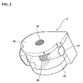
- a dust collection unit 2 which is constructed such that a primary dust collection using the cyclone method and a secondary dust collection using a filter can be performed. Accordingly, when the vacuum cleaner is operated, air containing foreign substances, which is sucked up through a suction nozzle 4, is introduced through an extension tube 6 and a connecting hose 8 into the main body 1 of the vacuum cleaner.
- the air introduced through an inlet port 21 into the dust collection unit 2 is formed into spiral flow within a casing 22. Relatively heavy foreign substances fall downwardly due to their own weight.
- the air from which the heavy foreign substances have been removed is introduced into a filter 23, and is then exhausted through an outlet 24 formed on an upper end of the filter.
- the filter 23 is installed on a bottom surface of a cover 25 for substantially opening and closing the casing 22.
- Such collection unit is advantageous in that the relatively heavy foreign substances can be removed through the primary dust collection using the cyclone method and even fine dusts can also be completely filtered out through the secondary dust collection using the filter 23.
- connection duct 26 which is constructed to connect the outlet 24 and a motor housing H contained within the main body of the vacuum cleaner above the dust collection unit 2. Accordingly, the connection duct 26 for connecting the outlet positioned on the top surface of the dust collection unit 2 and the motor housing H positioned lower than the dust collection unit within the main body of the vacuum cleaner is formed in a vertically downward direction.
- connection duct 26 should be used for connecting the dust collection unit 2 and the motor housing H, any suction loss may be generated at their respective connecting portions. Since this suction loss results in substantial reduction of the suction efficiency of the vacuum cleaner, it has an adverse influence on the performance of the vacuum cleaner. Furthermore, since the connection duct 26 is additionally installed, the number of parts is increased and the assembly process becomes complex. Thus, there are problems in that the production costs are increased and the productivity is lowered.
- An object of the present invention is to provide a dust collection unit constructed such that double filtering process using a cyclone method and a filter can be performed and simultaneously the inner structure of a main body of a vacuum cleaner can be more simplified, and a main body of a vacuum cleaner having the dust collection unit.
- a dust collection unit for use in a vacuum cleaner, comprising: a cylindrical casing in which air introduced through an inlet port is formed into spiral flow and of which an upper end is open; a cover for opening and closing the upper end of the casing; a filter which is installed on a bottom surface of the cover and formed in the shape of a cylinder having a predetermined length and by which fine foreign substances can be filtered out when the air is introduced from the exterior thereof, and through which the air is discharged downwardly; and an exhaust duct which comes into close contact with a bottom surface of the filter and including an exhaust port on a side surface of the casing to discharge the air from the filter to the exterior of the casing.
- the exhaust port is formed at a lower portion of the side surface of the casing.
- a horizontal separation plate is installed in the middle of the casing, and a dust collection hole is formed on the outer circumference of the separation plate.
- the separation plate includes a pair of semicircular plates, and the respective semicircular plates are pivoted only upwardly on a hinge end formed on an outer circumferential position thereof corresponding to an outmost position of the diameter thereof.
- a main body of a vacuum cleaner comprising: a motor housing installed within the main body of the vacuum cleaner for accommodating therein a motor for generating suction force; and a dust collection unit installed adjacent to the motor housing, and including an exhaust port through which, after filtering out foreign substances from air introduced by the suction force of the motor, the filtered air is exhausted, wherein the exhaust port of the dust collection unit is formed on a side surface of the dust collection unit so that the air can be introduced directly to the motor housing.
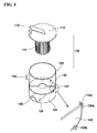
- FIG. 4 is an exploded perspective view of a dust collection unit 100 according to the present invention
- FIG. 6 is a longitudinal sectional view of the dust collection unit 100 according to the present invention.
- the dust collection unit 100 includes a casing 130 of which an upper end is open, and a cover 110 for opening and closing the upper end of the casing.
- the casing 130 defines a predetermined space therein and is formed in a cylindrical shape. As described later, air containing foreign substances, which is sucked into the casing, is the casing 130, is formed into spiral flow, and relatively heavy (large) foreign substances fall downwardly into the casing due to their own weight.
- An inlet port 134 is formed on one side of the casing 130. The inlet port 134 is designed to be tangential to an inner surface of the casing 130 so that the air introduced through the inlet port is formed into the spiral flow while flowing along the inner surface of the casing.
- the casing 130 is provided with an open upper end, and the cover 110 is installed on the upper end of the casing 130 so as to open and close the casing 130.
- a filter 114 is installed at a central portion of a bottom surface of the cover 110. It is preferred that the filter 114 is constructed to be detachably installed so that the filter can be easily exchanged and cleaned.
- the cover 110 is provided with a handle 116 so that a user grips the handle when separating it from the main body of the vacuum cleaner in a case where the filter is filled with the foreign substances such as dusts. Such a handle may also be formed on the casing 130.
- the filter 114 serves to filter out fine foreign substances such as dusts contained within air which is introduced into the casing.
- the filter 114 is formed in the shape of a hollow cylinder. In order to efficiently filter out the aforementioned fine dusts and the like, it is preferred that a contact area of the filter with the air be large as possible.
- the filter with a plurality of vertical folds formed on the external surface thereof is used to induce sufficient contact of the filter with the air so that the dusts can be efficiently collected.
- the filter is constructed such that the fine foreign substances contained within the air can be filtered out while the air within the casing 130 passes from the exterior to the interior of the filter, and the filtered air can be discharged to the exterior of the dust collection unit through an exhaust port 136 to be described later.
- the exhaust port 136 is formed on a lower portion of the casing 130.
- the exhaust port 136 serves to exhaust clean air, from which the fine dusts have been filtered out within the filter 114, to the exterior of the dust collection casing 100.
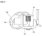
- the exhaust port is constructed such that the air from the exhaust port 136 can be introduced into a motor housing H to cool a drive motor within the motor housing, as shown in FIG. 5.
- the exhaust port 136 of the present invention is formed on a side surface of the casing 130, as shown in FIGS. 4 and 6.
- the exhaust port 136 is formed by an exhaust duct 138 which extends downwardly from a vertically middle portion of the casing 130 and then toward the side surface thereof.
- an upper end 138a of the exhaust duct 138 is constructed to come into close contact with a bottom surface of the cylindrical filter 114. That is, the air introduced from the exterior to the interior of the cylindrical filter 114 can be discharged through the central portion of the bottom surface of the filter 114, and the discharged air can be introduced directly into the exhaust duct 138.
- a separation plate 140 is installed in the middle of the inner surface of the casing 130 according to the present invention. It can be seen that a dust collection hole 142 is formed between an outer circumference of the separation plate 140 and the inner surface of the casing 130.
- the separation plate 140 is constructed preferably in the form of a pair of semicircular plates, and most preferably in the form of the plates which can be pivoted upwardly. These plates are used to discharge the foreign substances collected in the dust collection portion 144 to the exterior.
- a hinge end 140a at an outer circumferential position corresponding to an outmost position of the diameter of the semicircular separation plate 140 is pivotably supported onto a support portion 130a formed on the inner surface of the casing 130.
- the support portion 130a may be constructed in the form of a predetermined round groove so that the hinge end 140a of the separation plate 140 can be pivotably supported thereon.
- the support portion 130a may be constructed in the form of a hinge hole which is formed into an inner wall of the casing 130 to support the hinge end 140a of the separation plate 140.
- a support protrusion 130b is formed on the inner surface of the casing 130 to catch and support the separation plate 140. Since the separation plate 140 is placed and supported onto the support protrusion 130b, the separation plate 140 cannot be substantially pivoted downwardly, and thus can be pivoted only upwardly on the hinge end 140a.
- the dust collection unit 100 is installed within the main body 200 of the vacuum cleaner.
- the drive motor within the motor housing H is driven to generate a suction force by which the air containing the foreign substances is introduced through an inlet 202 of the main body 200.
- the air containing the foreign substances such as dusts are introduced into the dust collection unit 100 through the inlet port 134 installed on one side of the casing 130.
- the introduced air is formed into the spiral flow swirling along the inner surface within the casing 130. During the process, heavy foreign substances fall and are collected onto the bottom surface of the casing 130 due to their own weight.
- the heavy foreign substances falling downward due to their own weight are collected onto the bottom surface of the casing 130 through the dust collection hole 142 formed on the outer periphery of the separation plate 140.
- the air from which the relatively large foreign substances are removed is introduced into the cylindrical filter 114. Further, the foreign substances such as fine dusts are completely filtered out from the air while the air is passing through the filter 114. Thus, the completely filtered air is discharged through the central portion of the bottom surface of the filter 114.
- the air discharged through the central portion of the bottom surface of the center of the filter 114 is exhausted through the exhaust duct 138. This means that the air is discharged through the exhaust port 136 formed at the lower portion of the side surface of the casing 130.
- the air discharged through the exhaust port 136 can be introduced directly into the motor housing H which is disposed substantially parallel to and adjacent to the dust collection unit 100. Accordingly, the air cools the motor, which is installed within the motor housing H to generate the suction force, and is then discharged to the exterior, i.e. a room.
- the exhaust port 136 of the dust collection unit 100 is installed on the side surface of the casing 130 so that the air can be introduced directly into the motor housing H.
- an additional long, curved connection duct is not required since the air can be substantially introduced into the motor housing H through the shortest passage.
- the dust collection unit is connected directly to the motor housing H, the number of parts can be decreased and any suction loss generated between the dust collection unit and the motor housing can be minimized.
- the exhaust port 136 of the cyclone dust collection unit 100 is installed on the side surface of the casing 130 so that the exhaust port can be connected directly to the motor housing H.
- any suction loss of the air can be substantially minimized since the air is supplied through the shortest passage from the dust collection unit 100 to the motor housing.
- the inner constitution of the main body of the vacuum cleaner can be further simplified. Therefore, there is an advantage in that the number of parts can be reduced and the productivity in the assembly process can be enhanced.
Abstract
Description
Claims (13)
- A dust collection unit for use in a vacuum cleaner, comprising:a cylindrical casing in which air introduced through an inlet port is formed into spiral flow and of which an upper end is open;a cover for opening and closing the upper end of the casing;a filter which is installed on a bottom surface of the cover and formed in the shape of a cylinder having a predetermined length and by which fine foreign substances can be filtered out when the air is introduced into the filter from the exterior thereof, and through which the air is discharged downwardly; andan exhaust duct which comes into close contact with a bottom surface of the filter and including an exhaust port on a side surface of the casing to discharge the air from the filter to the exterior of the casing.
- The dust collection unit as claimed in claim 1, wherein the exhaust port is formed at a lower portion of the side surface of the casing.
- The dust collection unit as claimed in claim 1 or 2, wherein a handle is formed on the outer side surface of the casing.
- The dust collection unit as claimed in claim 1 or 2, wherein a handle is formed on one side surface of the cover.
- The dust collection unit as claimed in claim 1 or 2, wherein a horizontal separation plate is installed in the middle of the casing, and a dust collection hole is formed on the outer circumference of the separation plate.
- The dust collection unit as claimed in claim 5, wherein the separation plate includes a pair of semicircular plates, and the respective semicircular plates are pivoted only upwardly on a hinge end formed on an outer circumferential position thereof corresponding to an outmost position of the diameter thereof.
- A main body of a vacuum cleaner, comprising:wherein the exhaust port of the dust collection unit is formed on a side surface of the dust collection unit so that the air can be introduced directly to the motor housing.a motor housing installed within the main body of the vacuum cleaner for accommodating therein a motor for generating suction force; anda dust collection unit installed adjacent to the motor housing, and including an exhaust port through which, after filtering out foreign substances from air introduced by the suction force of the motor, the filtered air is exhausted,
- The main body as claimed in claim 7, wherein the dust collection unit comprises a cylindrical casing in which air introduced through an inlet port is formed into spiral flow and of which an upper end is open; a cover for opening and closing the upper end of the casing; a filter which is installed on a bottom surface of the cover and formed in the shape of a cylinder having a predetermined length and by which fine foreign substances can be filtered out when the air is introduced from the exterior thereof, and through which the air is discharged downwardly; and an exhaust duct which comes into close contact with a bottom surface of the filter and including the exhaust port on a side surface of the casing to discharge the air from the filter to the exterior of the casing.
- The main body as claimed in claim 7, wherein the exhaust port is formed at a lower portion of the side surface of the casing.
- The main body as claimed in claim 7, wherein a handle is formed on the outer side surface of the casing.
- The main body as claimed in claim 7, wherein a handle is formed on one side of the cover.
- The main body as claimed in claim 7, wherein a horizontal separation plate is installed in the middle of the casing, and a dust collection hole is formed on the outer circumference of the separation plate.
- The main body as claimed in claim 12, wherein the separation plate includes a pair of semicircular plates, and the respective semicircular plates are pivoted only upwardly on a hinge end formed on an outer circumferential position thereof corresponding to an outmost position of the diameter thereof.
Applications Claiming Priority (2)
| Application Number | Priority Date | Filing Date | Title |
|---|---|---|---|
| KR2001062163 | 2001-10-09 | ||
| KR10-2001-0062163A KR100445470B1 (en) | 2001-10-09 | 2001-10-09 | Dirt and dust collecting casing and vacuum cleaner body having the same |
Publications (3)
| Publication Number | Publication Date |
|---|---|
| EP1302148A2 true EP1302148A2 (en) | 2003-04-16 |
| EP1302148A3 EP1302148A3 (en) | 2005-01-12 |
| EP1302148B1 EP1302148B1 (en) | 2006-04-19 |
Family
ID=36314065
Family Applications (1)
| Application Number | Title | Priority Date | Filing Date |
|---|---|---|---|
| EP02011364A Expired - Lifetime EP1302148B1 (en) | 2001-10-09 | 2002-05-23 | Dust collection unit for use in vacuum cleaner and main body of vacuum cleaner having the same |
Country Status (12)
| Country | Link |
|---|---|
| US (1) | US6901625B2 (en) |
| EP (1) | EP1302148B1 (en) |
| JP (1) | JP2003116753A (en) |
| KR (1) | KR100445470B1 (en) |
| CN (1) | CN1265755C (en) |
| AT (1) | ATE323442T1 (en) |
| AU (1) | AU778983B2 (en) |
| DE (1) | DE60210721T2 (en) |
| DK (1) | DK1302148T3 (en) |
| ES (1) | ES2262728T3 (en) |
| PT (1) | PT1302148E (en) |
| RU (1) | RU2228704C2 (en) |
Cited By (9)
| Publication number | Priority date | Publication date | Assignee | Title |
|---|---|---|---|---|
| EP1477099A2 (en) * | 2003-05-10 | 2004-11-17 | LG Electronics Inc. | Dust collecting unit of vacuum cleaner |
| EP1488729A2 (en) * | 2003-06-16 | 2004-12-22 | Matsushita Electric Espana, S.A. | Waste receiving container for vacuum cleaners |
| GB2419833A (en) * | 2004-10-12 | 2006-05-10 | Samsung Kwangju Electronics Co | Filter arrangement for cyclone separator |
| WO2008070962A1 (en) * | 2006-12-12 | 2008-06-19 | Gbd Corp. | Surface cleaning apparatus |
| EP1535560A3 (en) * | 2003-10-28 | 2009-04-15 | LG Electronics Inc. | Dust-collecting device and vacuum cleaner for both wet and dry cleaning using the same |
| GB2457419A (en) * | 2006-12-12 | 2009-08-19 | Gbd Corp | Surface cleaning apparatus |
| US8146201B2 (en) | 2006-12-12 | 2012-04-03 | G.B.D. Corp. | Surface cleaning apparatus |
| US10271698B2 (en) | 2006-12-15 | 2019-04-30 | Omachron Intellectual Property Inc. | Surface cleaning apparatus |
| US11571098B2 (en) | 2006-12-12 | 2023-02-07 | Omachron Intellectual Property Inc. | Hand vacuum cleaner |
Families Citing this family (40)
| Publication number | Priority date | Publication date | Assignee | Title |
|---|---|---|---|---|
| GB0307929D0 (en) * | 2003-04-05 | 2003-05-14 | Hoover Ltd | Vacuum cleaner |
| KR100471142B1 (en) | 2003-05-21 | 2005-03-10 | 삼성광주전자 주식회사 | Cyclone dust collecting device and vacuum cleaner having the same |
| CN100358464C (en) * | 2003-09-27 | 2008-01-02 | 乐金电子(天津)电器有限公司 | Dust collecting unit in use for vacuum cleaner |
| CN100382740C (en) * | 2003-09-28 | 2008-04-23 | 乐金电子(天津)电器有限公司 | Structure for installing and separating dust collecting unit in vacuum cleaner |
| US7797790B2 (en) * | 2003-12-27 | 2010-09-21 | Lg Electronics Inc. | Dust collector of vacuum cleaner |
| US7640623B2 (en) * | 2004-03-11 | 2010-01-05 | Lg Electronics Inc. | Vacuum cleaner |
| KR100963383B1 (en) * | 2004-03-11 | 2010-06-14 | 엘지전자 주식회사 | A vacuum clearner |
| KR100934134B1 (en) * | 2004-03-11 | 2009-12-29 | 엘지전자 주식회사 | Dust collection assembly of vacuum cleaner |
| US20050198769A1 (en) * | 2004-03-11 | 2005-09-15 | Lg Electronics Inc. | Vacuum cleaner |
| US7779507B2 (en) | 2004-03-11 | 2010-08-24 | Lg Electronics Inc. | Vacuum cleaner |
| US7779506B2 (en) | 2004-03-11 | 2010-08-24 | Lg Electronics Inc. | Vacuum cleaner |
| KR100933188B1 (en) * | 2004-03-11 | 2009-12-22 | 엘지전자 주식회사 | Vacuum cleaner |
| US7669282B2 (en) | 2004-03-11 | 2010-03-02 | Lg Electronics Inc. | Vacuum cleaner |
| KR100944746B1 (en) | 2004-03-11 | 2010-03-03 | 엘지전자 주식회사 | A vacuum clearner |
| US20050198771A1 (en) * | 2004-03-11 | 2005-09-15 | Lg Electronics Inc. | Vacuum cleaner |
| KR100932760B1 (en) * | 2004-04-26 | 2009-12-21 | 엘지전자 주식회사 | Dust collection assembly of vacuum cleaner |
| KR100963337B1 (en) | 2004-08-23 | 2010-06-14 | 엘지전자 주식회사 | A dust collector for vacuum cleaner |
| US7918909B2 (en) * | 2004-09-01 | 2011-04-05 | Bissell Homecare, Inc. | Cyclone separator with fine particle separation member |
| KR100871484B1 (en) | 2004-12-14 | 2008-12-05 | 엘지전자 주식회사 | Dust and dirt Collecting unit for vacuum Cleaner |
| KR100623915B1 (en) | 2005-07-12 | 2006-09-15 | 삼성광주전자 주식회사 | Dust separating apparatus |
| CA2658372C (en) | 2009-03-13 | 2016-09-27 | G.B.D. Corp. | Surface cleaning apparatus |
| US11751733B2 (en) | 2007-08-29 | 2023-09-12 | Omachron Intellectual Property Inc. | Portable surface cleaning apparatus |
| US11690489B2 (en) | 2009-03-13 | 2023-07-04 | Omachron Intellectual Property Inc. | Surface cleaning apparatus with an external dirt chamber |
| US10722086B2 (en) | 2017-07-06 | 2020-07-28 | Omachron Intellectual Property Inc. | Handheld surface cleaning apparatus |
| US9211044B2 (en) | 2011-03-04 | 2015-12-15 | Omachron Intellectual Property Inc. | Compact surface cleaning apparatus |
| USD673155S1 (en) * | 2011-06-16 | 2012-12-25 | Pfu Limited | Scanner |
| CN103142190B (en) * | 2011-12-06 | 2017-02-15 | 南京乐金熊猫电器有限公司 | Dust-catcher dust collection bucket with bottom cover easy to open |
| US9456721B2 (en) | 2013-02-28 | 2016-10-04 | Omachron Intellectual Property Inc. | Surface cleaning apparatus |
| US20140237764A1 (en) | 2013-02-28 | 2014-08-28 | G.B.D. Corp. | Cyclone such as for use in a surface cleaning apparatus |
| US9775484B2 (en) | 2013-03-01 | 2017-10-03 | Omachron Intellectual Property Inc. | Surface cleaning apparatus |
| US10064530B2 (en) | 2015-09-16 | 2018-09-04 | Bissell Homecare, Inc. | Handheld vacuum cleaner |
| US10537216B2 (en) | 2017-07-06 | 2020-01-21 | Omachron Intellectual Property Inc. | Handheld surface cleaning apparatus |
| US10702113B2 (en) | 2017-07-06 | 2020-07-07 | Omachron Intellectual Property Inc. | Handheld surface cleaning apparatus |
| US10750913B2 (en) | 2017-07-06 | 2020-08-25 | Omachron Intellectual Property Inc. | Handheld surface cleaning apparatus |
| US10842330B2 (en) | 2017-07-06 | 2020-11-24 | Omachron Intellectual Property Inc. | Handheld surface cleaning apparatus |
| US10631693B2 (en) | 2017-07-06 | 2020-04-28 | Omachron Intellectual Property Inc. | Handheld surface cleaning apparatus |
| US10506904B2 (en) | 2017-07-06 | 2019-12-17 | Omachron Intellectual Property Inc. | Handheld surface cleaning apparatus |
| US11930987B2 (en) | 2018-04-20 | 2024-03-19 | Omachron Intellectual Property Inc. | Surface cleaning apparatus |
| US10932634B2 (en) | 2018-05-30 | 2021-03-02 | Omachron Intellectual Property Inc. | Surface cleaning apparatus |
| US10827889B2 (en) | 2018-05-30 | 2020-11-10 | Omachron Intellectual Property Inc. | Surface cleaning apparatus |
Citations (3)
| Publication number | Priority date | Publication date | Assignee | Title |
|---|---|---|---|---|
| US1133543A (en) * | 1915-02-25 | 1915-03-30 | Vacuum Specialty Mfg Co | Vacuum-cleaner. |
| US2616517A (en) * | 1948-08-30 | 1952-11-04 | Ideal Ind | Tank type cleaner |
| US6070291A (en) * | 1998-01-09 | 2000-06-06 | Royal Appliance Mfg. Co. | Upright vacuum cleaner with cyclonic air flow |
Family Cites Families (13)
| Publication number | Priority date | Publication date | Assignee | Title |
|---|---|---|---|---|
| NL7613475A (en) * | 1976-12-03 | 1978-06-06 | Philips Nv | VACUUM CLEANER. |
| KR20010026685A (en) * | 1999-09-08 | 2001-04-06 | 구자홍 | Cyclone dust collector |
| US6228260B1 (en) * | 1999-07-27 | 2001-05-08 | G. B. D. Corp. | Apparatus for separating particles from a cyclonic fluid flow |
| JP2001037687A (en) * | 1999-08-02 | 2001-02-13 | Matsushita Electric Ind Co Ltd | Vacuum cleaner |
| US6599350B1 (en) * | 1999-12-20 | 2003-07-29 | Hi-Stat Manufacturing Company, Inc. | Filtration device for use with a fuel vapor recovery system |
| AU754573B2 (en) * | 2000-06-16 | 2002-11-21 | Samsung Gwangju Electronics Co., Ltd. | Upright-type vacuum cleaner having a cyclone dust collecting apparatus |
| KR100377015B1 (en) * | 2000-08-07 | 2003-03-26 | 삼성광주전자 주식회사 | Cyclone dust-collecting apparatus for Vacuum Cleaner |
| JP3626413B2 (en) * | 2000-08-19 | 2005-03-09 | エルジー電子株式会社 | Dust collector and vacuum cleaner using the same |
| KR100478518B1 (en) * | 2000-11-17 | 2005-03-28 | 엘지전자 주식회사 | Vacuum cleaner |
| EP1188405A3 (en) * | 2000-09-19 | 2003-01-29 | Lg Electronics Inc. | Vacuum cleaner with improved cooling |
| KR100377016B1 (en) * | 2000-10-19 | 2003-03-26 | 삼성광주전자 주식회사 | Upright type Vacuum Cleaner |
| KR20020082630A (en) * | 2001-04-25 | 2002-10-31 | 주식회사 엘지이아이 | device for removing static electricity of cyclone type dust collector |
| JP3809607B2 (en) * | 2002-04-22 | 2006-08-16 | 三菱電機株式会社 | Vacuum cleaner |
-
2001
- 2001-10-09 KR KR10-2001-0062163A patent/KR100445470B1/en not_active IP Right Cessation
-
2002
- 2002-05-20 JP JP2002144381A patent/JP2003116753A/en active Pending
- 2002-05-21 US US10/151,158 patent/US6901625B2/en not_active Expired - Fee Related
- 2002-05-22 RU RU2002113400/12A patent/RU2228704C2/en not_active IP Right Cessation
- 2002-05-22 AU AU42443/02A patent/AU778983B2/en not_active Ceased
- 2002-05-23 CN CNB021206139A patent/CN1265755C/en not_active Expired - Fee Related
- 2002-05-23 EP EP02011364A patent/EP1302148B1/en not_active Expired - Lifetime
- 2002-05-23 PT PT02011364T patent/PT1302148E/en unknown
- 2002-05-23 DE DE60210721T patent/DE60210721T2/en not_active Expired - Fee Related
- 2002-05-23 DK DK02011364T patent/DK1302148T3/en active
- 2002-05-23 ES ES02011364T patent/ES2262728T3/en not_active Expired - Lifetime
- 2002-05-23 AT AT02011364T patent/ATE323442T1/en not_active IP Right Cessation
Patent Citations (3)
| Publication number | Priority date | Publication date | Assignee | Title |
|---|---|---|---|---|
| US1133543A (en) * | 1915-02-25 | 1915-03-30 | Vacuum Specialty Mfg Co | Vacuum-cleaner. |
| US2616517A (en) * | 1948-08-30 | 1952-11-04 | Ideal Ind | Tank type cleaner |
| US6070291A (en) * | 1998-01-09 | 2000-06-06 | Royal Appliance Mfg. Co. | Upright vacuum cleaner with cyclonic air flow |
Cited By (16)
| Publication number | Priority date | Publication date | Assignee | Title |
|---|---|---|---|---|
| US7409744B2 (en) | 2003-05-10 | 2008-08-12 | Lg Electronics, Inc. | Dust collecting unit of vacuum cleaner |
| EP1477099A3 (en) * | 2003-05-10 | 2007-06-20 | LG Electronics Inc. | Dust collecting unit of vacuum cleaner |
| EP1477099A2 (en) * | 2003-05-10 | 2004-11-17 | LG Electronics Inc. | Dust collecting unit of vacuum cleaner |
| EP1488729A2 (en) * | 2003-06-16 | 2004-12-22 | Matsushita Electric Espana, S.A. | Waste receiving container for vacuum cleaners |
| EP1488729A3 (en) * | 2003-06-16 | 2008-03-19 | Matsushita Electric Industrial Co., Ltd. | Waste receiving container for vacuum cleaners |
| EP1535560A3 (en) * | 2003-10-28 | 2009-04-15 | LG Electronics Inc. | Dust-collecting device and vacuum cleaner for both wet and dry cleaning using the same |
| AU2005201295B2 (en) * | 2004-10-12 | 2007-11-08 | Samsung Gwangju Electronics Co., Ltd. | Cyclone Dust Collecting Apparatus And Vacuum Cleaner Having The Same |
| GB2419833B (en) * | 2004-10-12 | 2008-03-19 | Samsung Kwangju Electronics Co | Cyclonic dust-collecting apparatus |
| GB2419833A (en) * | 2004-10-12 | 2006-05-10 | Samsung Kwangju Electronics Co | Filter arrangement for cyclone separator |
| WO2008070962A1 (en) * | 2006-12-12 | 2008-06-19 | Gbd Corp. | Surface cleaning apparatus |
| GB2457419A (en) * | 2006-12-12 | 2009-08-19 | Gbd Corp | Surface cleaning apparatus |
| GB2457419B (en) * | 2006-12-12 | 2011-11-23 | Gbd Corp | Surface cleaning apparatus |
| US8146201B2 (en) | 2006-12-12 | 2012-04-03 | G.B.D. Corp. | Surface cleaning apparatus |
| US11571098B2 (en) | 2006-12-12 | 2023-02-07 | Omachron Intellectual Property Inc. | Hand vacuum cleaner |
| US10271698B2 (en) | 2006-12-15 | 2019-04-30 | Omachron Intellectual Property Inc. | Surface cleaning apparatus |
| US10314447B2 (en) | 2006-12-15 | 2019-06-11 | Omachron Intellectual Property Inc. | Surface cleaning apparatus |
Also Published As
| Publication number | Publication date |
|---|---|
| PT1302148E (en) | 2006-08-31 |
| US20030066156A1 (en) | 2003-04-10 |
| EP1302148A3 (en) | 2005-01-12 |
| DE60210721T2 (en) | 2006-11-16 |
| DE60210721D1 (en) | 2006-05-24 |
| RU2228704C2 (en) | 2004-05-20 |
| ATE323442T1 (en) | 2006-05-15 |
| AU4244302A (en) | 2003-04-10 |
| KR100445470B1 (en) | 2004-08-21 |
| EP1302148B1 (en) | 2006-04-19 |
| KR20030030298A (en) | 2003-04-18 |
| CN1410027A (en) | 2003-04-16 |
| CN1265755C (en) | 2006-07-26 |
| ES2262728T3 (en) | 2006-12-01 |
| JP2003116753A (en) | 2003-04-22 |
| DK1302148T3 (en) | 2006-08-21 |
| AU778983B2 (en) | 2004-12-23 |
| US6901625B2 (en) | 2005-06-07 |
Similar Documents
| Publication | Publication Date | Title |
|---|---|---|
| EP1302148B1 (en) | Dust collection unit for use in vacuum cleaner and main body of vacuum cleaner having the same | |
| US6732406B2 (en) | Upright type vacuum cleaner | |
| US6532620B2 (en) | Cyclone dust collecting chamber for a vacuum cleaner | |
| US6579334B2 (en) | Cyclone dust collecting apparatus for vacuum cleaner | |
| JP4833929B2 (en) | Cyclone separator | |
| US7556662B2 (en) | Multi-cyclone dust separating apparatus | |
| JP4965477B2 (en) | Cyclone separator | |
| KR100776402B1 (en) | Multi cyclone separating apparatus having filter assembly | |
| RU2437611C2 (en) | Portable cleaning device | |
| KR100964699B1 (en) | Dust collecting device for vacuum cleaner | |
| JP2002051952A (en) | Vacuum cleaner | |
| KR20030072059A (en) | Vacuum cleaner | |
| JP2007152136A (en) | Suction cleaner | |
| JP2005185838A (en) | Cyclone dust collecting device for use in vacuum cleaner | |
| JP2005204880A (en) | Vacuum cleaner and its dust collector | |
| US7181803B2 (en) | Dual filter, upright vacuum cleaner with detachable hose | |
| JP2003339596A (en) | Dust collecting apparatus and vacuum cleaner | |
| KR20020085478A (en) | Cyclone device for vacuum cleaner | |
| KR100540439B1 (en) | Dirt and dust collecting casing for vacuum cleaner | |
| US20040064912A1 (en) | Dust and dirt collecting unit for vacuum cleaner | |
| KR100657922B1 (en) | Vacuum cleaner | |
| KR100603523B1 (en) | Vacuum cleaner | |
| KR100565574B1 (en) | A cyclone type dust collector for a vacuum cleaner |
Legal Events
| Date | Code | Title | Description |
|---|---|---|---|
| PUAI | Public reference made under article 153(3) epc to a published international application that has entered the european phase |
Free format text: ORIGINAL CODE: 0009012 |
|
| 17P | Request for examination filed |
Effective date: 20020523 |
|
| AK | Designated contracting states |
Designated state(s): AT BE CH CY DE DK ES FI FR GB GR IE IT LI LU MC NL PT SE TR |
|
| AX | Request for extension of the european patent |
Extension state: AL LT LV MK RO SI |
|
| PUAL | Search report despatched |
Free format text: ORIGINAL CODE: 0009013 |
|
| AK | Designated contracting states |
Kind code of ref document: A3 Designated state(s): AT BE CH CY DE DK ES FI FR GB GR IE IT LI LU MC NL PT SE TR |
|
| AX | Request for extension of the european patent |
Extension state: AL LT LV MK RO SI |
|
| RIC1 | Information provided on ipc code assigned before grant |
Ipc: 7A 47L 9/16 A Ipc: 7A 47L 5/36 B |
|
| RIN1 | Information on inventor provided before grant (corrected) |
Inventor name: BYUNG-SUN, YANG Inventor name: YOO, MYUNG-SIG |
|
| RIN1 | Information on inventor provided before grant (corrected) |
Inventor name: YOO, MYUNG-SIG Inventor name: BYUNG-SUN, YANG |
|
| AKX | Designation fees paid |
Designated state(s): AT BE CH CY DE DK ES FI FR GB GR IE IT LI LU MC NL PT SE TR |
|
| GRAP | Despatch of communication of intention to grant a patent |
Free format text: ORIGINAL CODE: EPIDOSNIGR1 |
|
| GRAS | Grant fee paid |
Free format text: ORIGINAL CODE: EPIDOSNIGR3 |
|
| GRAA | (expected) grant |
Free format text: ORIGINAL CODE: 0009210 |
|
| AK | Designated contracting states |
Kind code of ref document: B1 Designated state(s): AT BE CH CY DE DK ES FI FR GB GR IE IT LI LU MC NL PT SE TR |
|
| REG | Reference to a national code |
Ref country code: GB Ref legal event code: FG4D |
|
| REG | Reference to a national code |
Ref country code: CH Ref legal event code: NV Representative=s name: E. BLUM & CO. PATENTANWAELTE |
|
| PG25 | Lapsed in a contracting state [announced via postgrant information from national office to epo] |
Ref country code: AT Free format text: LAPSE BECAUSE OF NON-PAYMENT OF DUE FEES Effective date: 20060523 Ref country code: IE Free format text: LAPSE BECAUSE OF NON-PAYMENT OF DUE FEES Effective date: 20060523 |
|
| REF | Corresponds to: |
Ref document number: 60210721 Country of ref document: DE Date of ref document: 20060524 Kind code of ref document: P |
|
| PGFP | Annual fee paid to national office [announced via postgrant information from national office to epo] |
Ref country code: ES Payment date: 20060526 Year of fee payment: 5 |
|
| PG25 | Lapsed in a contracting state [announced via postgrant information from national office to epo] |
Ref country code: BE Free format text: LAPSE BECAUSE OF NON-PAYMENT OF DUE FEES Effective date: 20060531 Ref country code: CH Free format text: LAPSE BECAUSE OF NON-PAYMENT OF DUE FEES Effective date: 20060531 Ref country code: LI Free format text: LAPSE BECAUSE OF NON-PAYMENT OF DUE FEES Effective date: 20060531 Ref country code: MC Free format text: LAPSE BECAUSE OF NON-PAYMENT OF DUE FEES Effective date: 20060531 |
|
| REG | Reference to a national code |
Ref country code: IE Ref legal event code: FG4D |
|
| REG | Reference to a national code |
Ref country code: GR Ref legal event code: EP Ref document number: 20060401806 Country of ref document: GR |
|
| PG25 | Lapsed in a contracting state [announced via postgrant information from national office to epo] |
Ref country code: FI Free format text: LAPSE BECAUSE OF NON-PAYMENT OF DUE FEES Effective date: 20060723 |
|
| PG25 | Lapsed in a contracting state [announced via postgrant information from national office to epo] |
Ref country code: DK Free format text: LAPSE BECAUSE OF NON-PAYMENT OF DUE FEES Effective date: 20060731 |
|
| REG | Reference to a national code |
Ref country code: SE Ref legal event code: TRGR |
|
| REG | Reference to a national code |
Ref country code: DK Ref legal event code: T3 |
|
| REG | Reference to a national code |
Ref country code: PT Ref legal event code: SC4A Effective date: 20060616 |
|
| ET | Fr: translation filed | ||
| PG25 | Lapsed in a contracting state [announced via postgrant information from national office to epo] |
Ref country code: NL Free format text: LAPSE BECAUSE OF NON-PAYMENT OF DUE FEES Effective date: 20061201 |
|
| REG | Reference to a national code |
Ref country code: ES Ref legal event code: FG2A Ref document number: 2262728 Country of ref document: ES Kind code of ref document: T3 |
|
| REG | Reference to a national code |
Ref country code: CH Ref legal event code: PL |
|
| NLV4 | Nl: lapsed or anulled due to non-payment of the annual fee |
Effective date: 20061201 |
|
| PLBE | No opposition filed within time limit |
Free format text: ORIGINAL CODE: 0009261 |
|
| STAA | Information on the status of an ep patent application or granted ep patent |
Free format text: STATUS: NO OPPOSITION FILED WITHIN TIME LIMIT |
|
| REG | Reference to a national code |
Ref country code: DK Ref legal event code: EBP |
|
| 26N | No opposition filed |
Effective date: 20070122 |
|
| BERE | Be: lapsed |
Owner name: *LG ELECTRONICS INC. Effective date: 20060531 |
|
| REG | Reference to a national code |
Ref country code: PT Ref legal event code: MM4A Free format text: LAPSE DUE TO NON-PAYMENT OF FEES Effective date: 20080225 |
|
| PG25 | Lapsed in a contracting state [announced via postgrant information from national office to epo] |
Ref country code: GR Free format text: LAPSE BECAUSE OF NON-PAYMENT OF DUE FEES Effective date: 20060720 |
|
| PG25 | Lapsed in a contracting state [announced via postgrant information from national office to epo] |
Ref country code: CY Free format text: LAPSE BECAUSE OF NON-PAYMENT OF DUE FEES Effective date: 20070523 Ref country code: PT Free format text: LAPSE BECAUSE OF NON-PAYMENT OF DUE FEES Effective date: 20080225 |
|
| PG25 | Lapsed in a contracting state [announced via postgrant information from national office to epo] |
Ref country code: LU Free format text: LAPSE BECAUSE OF NON-PAYMENT OF DUE FEES Effective date: 20060523 |
|
| PGFP | Annual fee paid to national office [announced via postgrant information from national office to epo] |
Ref country code: DE Payment date: 20080529 Year of fee payment: 7 |
|
| REG | Reference to a national code |
Ref country code: ES Ref legal event code: FD2A Effective date: 20070524 |
|
| PG25 | Lapsed in a contracting state [announced via postgrant information from national office to epo] |
Ref country code: ES Free format text: LAPSE BECAUSE OF NON-PAYMENT OF DUE FEES Effective date: 20070524 |
|
| PGFP | Annual fee paid to national office [announced via postgrant information from national office to epo] |
Ref country code: SE Payment date: 20080509 Year of fee payment: 7 |
|
| PG25 | Lapsed in a contracting state [announced via postgrant information from national office to epo] |
Ref country code: CY Free format text: LAPSE BECAUSE OF NON-PAYMENT OF DUE FEES Effective date: 20060523 |
|
| PG25 | Lapsed in a contracting state [announced via postgrant information from national office to epo] |
Ref country code: TR Free format text: LAPSE BECAUSE OF FAILURE TO SUBMIT A TRANSLATION OF THE DESCRIPTION OR TO PAY THE FEE WITHIN THE PRESCRIBED TIME-LIMIT Effective date: 20060419 |
|
| PG25 | Lapsed in a contracting state [announced via postgrant information from national office to epo] |
Ref country code: DE Free format text: LAPSE BECAUSE OF NON-PAYMENT OF DUE FEES Effective date: 20091201 |
|
| PG25 | Lapsed in a contracting state [announced via postgrant information from national office to epo] |
Ref country code: SE Free format text: LAPSE BECAUSE OF NON-PAYMENT OF DUE FEES Effective date: 20090524 |
|
| PGFP | Annual fee paid to national office [announced via postgrant information from national office to epo] |
Ref country code: GB Payment date: 20140411 Year of fee payment: 13 |
|
| PGFP | Annual fee paid to national office [announced via postgrant information from national office to epo] |
Ref country code: FR Payment date: 20140414 Year of fee payment: 13 Ref country code: IT Payment date: 20140513 Year of fee payment: 13 |
|
| GBPC | Gb: european patent ceased through non-payment of renewal fee |
Effective date: 20150523 |
|
| PG25 | Lapsed in a contracting state [announced via postgrant information from national office to epo] |
Ref country code: IT Free format text: LAPSE BECAUSE OF NON-PAYMENT OF DUE FEES Effective date: 20150523 |
|
| REG | Reference to a national code |
Ref country code: FR Ref legal event code: ST Effective date: 20160129 |
|
| PG25 | Lapsed in a contracting state [announced via postgrant information from national office to epo] |
Ref country code: GB Free format text: LAPSE BECAUSE OF NON-PAYMENT OF DUE FEES Effective date: 20150523 |
|
| PG25 | Lapsed in a contracting state [announced via postgrant information from national office to epo] |
Ref country code: FR Free format text: LAPSE BECAUSE OF NON-PAYMENT OF DUE FEES Effective date: 20150601 |