EP1306592A2 - Etanchéité pour pression differentielle avec fluide pompé - Google Patents
Etanchéité pour pression differentielle avec fluide pompé Download PDFInfo
- Publication number
- EP1306592A2 EP1306592A2 EP02023879A EP02023879A EP1306592A2 EP 1306592 A2 EP1306592 A2 EP 1306592A2 EP 02023879 A EP02023879 A EP 02023879A EP 02023879 A EP02023879 A EP 02023879A EP 1306592 A2 EP1306592 A2 EP 1306592A2
- Authority
- EP
- European Patent Office
- Prior art keywords
- seal
- space
- differential pumping
- pumping seal
- gap
- Prior art date
- Legal status (The legal status is an assumption and is not a legal conclusion. Google has not performed a legal analysis and makes no representation as to the accuracy of the status listed.)
- Granted
Links
Images


Classifications
-
- G—PHYSICS
- G03—PHOTOGRAPHY; CINEMATOGRAPHY; ANALOGOUS TECHNIQUES USING WAVES OTHER THAN OPTICAL WAVES; ELECTROGRAPHY; HOLOGRAPHY
- G03F—PHOTOMECHANICAL PRODUCTION OF TEXTURED OR PATTERNED SURFACES, e.g. FOR PRINTING, FOR PROCESSING OF SEMICONDUCTOR DEVICES; MATERIALS THEREFOR; ORIGINALS THEREFOR; APPARATUS SPECIALLY ADAPTED THEREFOR
- G03F7/00—Photomechanical, e.g. photolithographic, production of textured or patterned surfaces, e.g. printing surfaces; Materials therefor, e.g. comprising photoresists; Apparatus specially adapted therefor
- G03F7/70—Microphotolithographic exposure; Apparatus therefor
- G03F7/708—Construction of apparatus, e.g. environment aspects, hygiene aspects or materials
- G03F7/70808—Construction details, e.g. housing, load-lock, seals or windows for passing light in or out of apparatus
- G03F7/70841—Constructional issues related to vacuum environment, e.g. load-lock chamber
-
- F—MECHANICAL ENGINEERING; LIGHTING; HEATING; WEAPONS; BLASTING
- F16—ENGINEERING ELEMENTS AND UNITS; GENERAL MEASURES FOR PRODUCING AND MAINTAINING EFFECTIVE FUNCTIONING OF MACHINES OR INSTALLATIONS; THERMAL INSULATION IN GENERAL
- F16C—SHAFTS; FLEXIBLE SHAFTS; ELEMENTS OR CRANKSHAFT MECHANISMS; ROTARY BODIES OTHER THAN GEARING ELEMENTS; BEARINGS
- F16C29/00—Bearings for parts moving only linearly
- F16C29/02—Sliding-contact bearings
- F16C29/025—Hydrostatic or aerostatic
-
- F—MECHANICAL ENGINEERING; LIGHTING; HEATING; WEAPONS; BLASTING
- F16—ENGINEERING ELEMENTS AND UNITS; GENERAL MEASURES FOR PRODUCING AND MAINTAINING EFFECTIVE FUNCTIONING OF MACHINES OR INSTALLATIONS; THERMAL INSULATION IN GENERAL
- F16C—SHAFTS; FLEXIBLE SHAFTS; ELEMENTS OR CRANKSHAFT MECHANISMS; ROTARY BODIES OTHER THAN GEARING ELEMENTS; BEARINGS
- F16C29/00—Bearings for parts moving only linearly
- F16C29/08—Arrangements for covering or protecting the ways
-
- F—MECHANICAL ENGINEERING; LIGHTING; HEATING; WEAPONS; BLASTING
- F16—ENGINEERING ELEMENTS AND UNITS; GENERAL MEASURES FOR PRODUCING AND MAINTAINING EFFECTIVE FUNCTIONING OF MACHINES OR INSTALLATIONS; THERMAL INSULATION IN GENERAL
- F16C—SHAFTS; FLEXIBLE SHAFTS; ELEMENTS OR CRANKSHAFT MECHANISMS; ROTARY BODIES OTHER THAN GEARING ELEMENTS; BEARINGS
- F16C32/00—Bearings not otherwise provided for
- F16C32/06—Bearings not otherwise provided for with moving member supported by a fluid cushion formed, at least to a large extent, otherwise than by movement of the shaft, e.g. hydrostatic air-cushion bearings
- F16C32/0603—Bearings not otherwise provided for with moving member supported by a fluid cushion formed, at least to a large extent, otherwise than by movement of the shaft, e.g. hydrostatic air-cushion bearings supported by a gas cushion, e.g. an air cushion
- F16C32/0614—Bearings not otherwise provided for with moving member supported by a fluid cushion formed, at least to a large extent, otherwise than by movement of the shaft, e.g. hydrostatic air-cushion bearings supported by a gas cushion, e.g. an air cushion the gas being supplied under pressure, e.g. aerostatic bearings
-
- F—MECHANICAL ENGINEERING; LIGHTING; HEATING; WEAPONS; BLASTING
- F16—ENGINEERING ELEMENTS AND UNITS; GENERAL MEASURES FOR PRODUCING AND MAINTAINING EFFECTIVE FUNCTIONING OF MACHINES OR INSTALLATIONS; THERMAL INSULATION IN GENERAL
- F16C—SHAFTS; FLEXIBLE SHAFTS; ELEMENTS OR CRANKSHAFT MECHANISMS; ROTARY BODIES OTHER THAN GEARING ELEMENTS; BEARINGS
- F16C33/00—Parts of bearings; Special methods for making bearings or parts thereof
- F16C33/72—Sealings
- F16C33/74—Sealings of sliding-contact bearings
- F16C33/741—Sealings of sliding-contact bearings by means of a fluid
- F16C33/748—Sealings of sliding-contact bearings by means of a fluid flowing to or from the sealing gap, e.g. vacuum seals with differential exhaust
-
- F—MECHANICAL ENGINEERING; LIGHTING; HEATING; WEAPONS; BLASTING
- F16—ENGINEERING ELEMENTS AND UNITS; GENERAL MEASURES FOR PRODUCING AND MAINTAINING EFFECTIVE FUNCTIONING OF MACHINES OR INSTALLATIONS; THERMAL INSULATION IN GENERAL
- F16J—PISTONS; CYLINDERS; SEALINGS
- F16J15/00—Sealings
- F16J15/16—Sealings between relatively-moving surfaces
- F16J15/40—Sealings between relatively-moving surfaces by means of fluid
- F16J15/406—Sealings between relatively-moving surfaces by means of fluid by at least one pump
-
- G—PHYSICS
- G03—PHOTOGRAPHY; CINEMATOGRAPHY; ANALOGOUS TECHNIQUES USING WAVES OTHER THAN OPTICAL WAVES; ELECTROGRAPHY; HOLOGRAPHY
- G03F—PHOTOMECHANICAL PRODUCTION OF TEXTURED OR PATTERNED SURFACES, e.g. FOR PRINTING, FOR PROCESSING OF SEMICONDUCTOR DEVICES; MATERIALS THEREFOR; ORIGINALS THEREFOR; APPARATUS SPECIALLY ADAPTED THEREFOR
- G03F7/00—Photomechanical, e.g. photolithographic, production of textured or patterned surfaces, e.g. printing surfaces; Materials therefor, e.g. comprising photoresists; Apparatus specially adapted therefor
- G03F7/70—Microphotolithographic exposure; Apparatus therefor
- G03F7/708—Construction of apparatus, e.g. environment aspects, hygiene aspects or materials
- G03F7/70808—Construction details, e.g. housing, load-lock, seals or windows for passing light in or out of apparatus
- G03F7/70816—Bearings
-
- F—MECHANICAL ENGINEERING; LIGHTING; HEATING; WEAPONS; BLASTING
- F16—ENGINEERING ELEMENTS AND UNITS; GENERAL MEASURES FOR PRODUCING AND MAINTAINING EFFECTIVE FUNCTIONING OF MACHINES OR INSTALLATIONS; THERMAL INSULATION IN GENERAL
- F16C—SHAFTS; FLEXIBLE SHAFTS; ELEMENTS OR CRANKSHAFT MECHANISMS; ROTARY BODIES OTHER THAN GEARING ELEMENTS; BEARINGS
- F16C2300/00—Application independent of particular apparatuses
- F16C2300/40—Application independent of particular apparatuses related to environment, i.e. operating conditions
- F16C2300/62—Application independent of particular apparatuses related to environment, i.e. operating conditions low pressure, e.g. elements operating under vacuum conditions
-
- Y—GENERAL TAGGING OF NEW TECHNOLOGICAL DEVELOPMENTS; GENERAL TAGGING OF CROSS-SECTIONAL TECHNOLOGIES SPANNING OVER SEVERAL SECTIONS OF THE IPC; TECHNICAL SUBJECTS COVERED BY FORMER USPC CROSS-REFERENCE ART COLLECTIONS [XRACs] AND DIGESTS
- Y10—TECHNICAL SUBJECTS COVERED BY FORMER USPC
- Y10S—TECHNICAL SUBJECTS COVERED BY FORMER USPC CROSS-REFERENCE ART COLLECTIONS [XRACs] AND DIGESTS
- Y10S277/00—Seal for a joint or juncture
- Y10S277/914—Backup seal for failure of primary seal
Definitions
- the present invention relates to a differential pumping seal apparatus for use as a part of a semiconductor fabrication apparatus or the like, and more particularly to an improved differential pumping seal apparatus having a seal element referred to as a differential pumping seal for sealing a gap between a space defined by a fixed member and a movable body movable with respect to the fixed member, and another space having an atmosphere which is different from an atmosphere in the above space with respect to a pressure, cleanliness, type of a gas, or the like in a non-contact manner.
- a differential pumping seal is disclosed in U.S. patent No. 4,118,042 entitled “Air Bearing Vacuum Seal Assembly”, filed in 1977, and U.S. patent No. 4,191,385 entitled “Vacuum sealed Gas bearing Assembly”, filed in 1979.
- a differential pumping seal used in a semiconductor fabrication apparatus is disclosed in U.S. patent No. 4,425,508 entitled “Electron beam Lithographic Apparatus", filed in 1982.
- the conventional differential pumping seal has been used for moving an object quickly and smoothly in a rotary-motion manner or in a linear-motion manner within a clean space such as a vacuum space without contaminating the clean space.
- the differential pumping seal is used in the case where an actuator for moving the object, a guide mechanism for guiding the object, and other components are placed outside of the clean space, and only a minimum structural assembly and the object such as a specimen are adapted to be disposed in the clean space.
- the differential pumping seal is used in the case where a hydrostatic fluid bearing such as an air bearing is used for sealing two spaces from each other without impairing the advantage of a non-contact bearing.
- the differential pumping seal is used for sealing the two spaces from each other in the following situation:
- the differential pumping seal is capable of separating two spaces from each other in a non-contact fashion. This feature is recognized as a great advantage, and the differential pumping seal tends to be applied to practical apparatuses.
- the differential pumping seal When the differential pumping seal is in a normal or steady state in which the differential pumping seal functions normally, the differential pumping seal can certainly perform an excellent function as a non-contact seal.
- it is necessary to sufficiently recognize the effects (features) of the differential pumping seal when the differential pumping seal is in an unsteady state in which the differential pumping seal does not function normally.
- the differential pumping seal When an apparatus having a differential pumping seal is in operation, the failure of a continuous sealing function may occur due to an emergency shutdown of the apparatus, or the entire apparatus including the differential pumping seal may be brought out of operation. When such cases occur, the differential pumping seal has a disadvantage resulted from a non-contact seal. This disadvantage can easily be imagined because an invisible and virtual wall which has separated the two spaces from each other is eliminated when the sealing function is stopped. For example, when operation of the differential pumping seal which has separated a clean space (vacuum space) and a space (the atmosphere) outside of the clean space from each other in a non-contact manner is suddenly stopped, the vacuum space which has been kept clean is instantly filled with air of the atmosphere.
- a clean space vacuum space
- the atmosphere the atmosphere
- a substance which has a greatest effect on the degree of vacuum is water, which is typical of moisture of the atmosphere.
- the humidity in a clean room is normally in the range of about 40 to 55 %, and thus a gas in the clean room contains a large quantity of moisture. If air of the atmosphere flows into the clean room each time the differential pumping seal stops its sealing function, then it is difficult to increase the degree of vacuum in a vacuum chamber which is to be cleaned. Further, there is a possibility that particles in the atmosphere outside of the vacuum chamber enter the vacuum chamber. In an apparatus having an ordinary vacuum chamber, no atmosphere is introduced into the vacuum chamber, and the humidity of a gas which is introduced into the vacuum chamber is controlled at an extremely low degree.
- the vacuum chamber is the same as a vacuum chamber whose partition wall for separating the vacuum chamber from the exterior has a large crack. Therefore, the differential pumping seal is, so to speak, a troublesome apparatus from the standpoint of the commonsense in the field of the conventional vacuum apparatus.
- the conventional differential pumping seal (non-contact seal) has an operational disadvantage in an apparatus incorporating the differential pumping seal such as a vacuum apparatus which requires a cleanliness of an atmosphere.
- the present invention has been made in view of the above drawbacks. It is an object of the present invention to provide a differential pumping seal apparatus which can eliminate the disadvantage of a conventional differential pumping seal serving as a non-contact seal, and can maintain a space sealed by the differential pumping seal in a state before operation of the differential pumping seal is stopped, e.g., can maintain a clean space in a clean state, even when operation of the differential pumping seal is stopped or while operation of the differential pumping seal is stopped.
- Another object of the present invention is to provide a differential pumping seal apparatus having a differential pumping seal for sealing a gap between two spaces whose atmospheres are different from each other, specifically, a differential pumping seal apparatus having a diaphragm seal member which does not function when the differential pumping seal functions normally and is in a stable state, and which functions when the differential pumping seal does not function normally and is in an unstable state in such a manner that the diaphragm seal member is brought into contact with a member defining the gap by a fluid pressure for thereby interrupting the communication between the two spaces.
- Still another object of the present invention is to provide a differential pumping seal apparatus having a differential pumping seal for sealing a gap between two spaces whose atmospheres are different from each other, specifically, a differential pumping seal apparatus having a seal member which does not function when the differential pumping seal functions normally and is in a stable state, and which functions when the differential pumping seal does not function normally and is in an unstable state in such a manner that one of two members which define the gap is pushed toward the other member by a pushing means to bring the one of the two members into contact with a seal member for thereby interrupting the communication between the two spaces.
- a differential pumping seal apparatus comprising: a differential pumping seal for sealing a first space and a second space from each other in a non-contact manner; and a back up seal mechanism for sealing the first space and the second space from each other in a contact manner; wherein the back up seal mechanism seals the first space and the second space from each other only when operation of the differential pumping seal is stopped or while operation of the differential pumping seal is stopped.
- the back up seal mechanism is provided for sealing the first space and the second space from each other only when operation of the differential pumping seal is stopped or while operation of the differential pumping seal is stopped, the first space and the second space can be maintained in a state which is substantially the same as a state which is achieved when the differential pumping seal is in operation even when operation of the differential pumping seal is stopped or while operation of the differential pumping seal is stopped.
- the back up seal mechanism comprises a seal member for sealing the first space and the second space from each other, and the seal member is kept in a non-contact state by the force of a fluid or an external force so as not to perform the sealing function thereof when the differential pumping seal is in operation, and the seal member is kept in a contact state by its own elasticity or an external force so as to perform the sealing function thereof when the differential pumping seal is not in operation.
- the seal member since the seal member is kept in a non-contact state by the force of the fluid or the external force so as not to exercise the sealing function thereof when the differential pumping seal is in operation, and the seal member is kept in a contact state by its own elasticity or the external force to exercise the sealing function thereof when the differential pumping seal is not in operation, the structure of the back up seal can be simplified.
- a differential pumping seal apparatus comprising: a partition wall for dividing a first space and a second space from each other; a movable body provided so as to pass through the partition wall; a differential pumping seal for sealing the first space and the second space from each other in a non-contact manner; and a back up seal mechanism for closing a gap between the partition wall and the movable body in a contact manner so as to seal the first space and the second space from each other; wherein the back up seal mechanism seals the first space and the second space from each other only when operation of the differential pumping seal is stopped or while operation of the differential pumping seal is stopped.
- the back up seal mechanism is provided for sealing the first space and the second space from each other only when operation of the differential pumping seal is stopped or while operation of the differential pumping seal is stopped, the first space and the second space can be maintained in a state which is substantially the same as a state which is achieved when the differential pumping seal is in operation even when operation of the differential pumping seal is stopped or while operation of the differential pumping seal is stopped.
- the back up seal mechanism has a shutter mechanism for opening and closing the gap between the partition wall and the movable body, and the shutter mechanism is operated to seal the first space and the second space from each other only when operation of the differential pumping seal is stopped or while operation of the differential pumping seal is stopped.
- the back up seal mechanism since the back up seal mechanism has the shutter mechanism for closing the gap between the partition wall and the movable body only when operation of the differential pumping seal is stopped or while operation of the differential pumping seal is stopped, the structure of the back up seal mechanism can be simplified.
- the back up seal mechanism has a seal member provided on the partition wall or the movable body, and the seal member is brought into contact with the partition wall or the movable body by its own elasticity so as to perform a sealing function thereof when the differential pumping seal is not in operation, and the seal member is kept out of contact with the partition wall or the movable body by the force of a fluid so as not to perform the sealing function thereof when the differential pumping seal is in operation.
- the seal member is brought into contact with the partition wall or the movable body by its own elasticity so as to perform a sealing function thereof when the differential pumping seal is not in operation, and the seal member is kept out of contact with the partition wall or the movable body by the force of a fluid so as not to exercise the sealing function thereof when the differential pumping seal is in operation.
- a differential pumping seal apparatus comprising: a first member for defining at least one of a first space and a second space whose atmospheres are different from each other; a second member movable relatively to the first member; a differential pumping seal for sealing a gap between the first space and the second space in a non-contact manner; and a seal element for separating the first space and the second space from each other in a contact manner only when the differential pumping seal does not function; wherein the seal element comprises a diaphragm seal member which is extensible and has an edge portion fixed to the first member, and the diaphragm seal member projects toward the second member by a fluid pressure so as to be brought into contact with the second member.
- the communication between the first and second spaces can effectively be interrupted by the seal element even when the differential pumping seal does not function.
- the diaphragm seal member has a structure capable of performing its function without being supplied with energy when its sealing function is to be performed, and can keep its sealing function in a contact state (a state with a low energy level).
- the gap is formed on both sides of the first space, and the differential pumping seal for sealing the gap is provided at a position where the second member passes through the first member.
- a differential pumping seal apparatus comprising: a first member for defining at least one of a first space and a second space whose atmospheres are different from each other; a second member movable relatively to the first member; a differential pumping seal for sealing a gap between the first space and the second space in a non-contact manner, the gap being formed only on one side of the second member, one of the first and second spaces being defined by the first member and the second member; a seal element for separating the first space and the second space from each other in a contact manner only when the differential pumping seal does not function, the seal element comprising a fixed seal member which is fixed to the first member and is capable of being brought into contact with the second member; and a push device for pushing the second member toward the first member to bring the second member into contact with the fixed seal member only when the differential pumping seal does not function.
- the communication between the first and second spaces can effectively be interrupted by the seal element even when the differential pumping seal does not function.
- the fixed seal member has a structure capable of performing its function without being supplied with energy when its sealing function is to be performed, and can keep its sealing function in a contact state (a state with a low energy level).
- the differential pumping seal apparatus further comprises a hydrostatic bearing which performs the bearing function in the gap; the hydrostatic bearing and the differential pumping seal being adjacent to each other in the gap, the hydrostatic bearing being disposed at a position where the hydrostatic bearing is closer to the second space than the differential pumping seal, and the seal element being disposed between the hydrostatic bearing and the second space.
- a differential pumping seal apparatus having a differential pumping seal and a hydrostatic bearing according to a first embodiment of the present invention will be described with reference to FIGS. 1 and 2.
- FIGS. 1 and 2 the differential pumping seal and the hydrostatic bearing are illustrated in a simplified manner so as to be easily understood.
- a partition wall 3 is disposed between a clean space region 1 serving as a first space and an atmospheric region 2 serving as a second space.
- a movable body 4 is provided so as to pass through the partition wall 3.
- An actuator (not shown) is disposed in the atmospheric region 2 and is coupled to the movable body 4.
- An object such as a specimen (not shown) which is disposed in the clean space region 1 can be moved by the movable body 4.
- the differential pumping seal apparatus comprises a differential pumping seal 5 for separating the clean space region 1 and the atmospheric region 2 from each other, and a hydrostatic bearing 6 for supporting the movable body 4 in a non-contact manner.
- the differential pumping seal 5 and the hydrostatic bearing 6 allow the movable body 4 to move smoothly without being subjected to a sliding resistance.
- the differential pumping seal 5 has a plurality of pump grooves 5-1, 5-2 and 5-3 having respective pump ports connected to an evacuating system via valves (not shown).
- a working fluid supply port 6-1 of the hydrostatic bearing 6 communicates with a working fluid supply source via a valve (not shown) , and a working fluid is supplied from the working fluid supply source to the working fluid supply port 6-1 which is then kept at a pressure of P1.
- Pump ports of the respective pump grooves 5-1, 5-2 and 5-3 of the differential pumping seal 5 communicate with the evacuating system, so that the pump ports are kept at pressures of V2, V3 and V4, respectively.
- the clean space region 1 communicates with the evacuating system via a valve (not shown), and the clean space region 1 is kept at a pressure of V1.
- a back up seal mechanism 7 is disposed on the partition wall 3 at a position near the atmospheric region 2.
- the back up seal mechanism is operated when the differential pumping seal 5 is not in operation, i.e., is not in a normal or stable state.
- the back up seal mechanism 7 has a seal member 8 movable into and out of the surface of the partition wall 3 which faces the movable body 4.
- FIG. 1 shows the differential pumping seal 5 which is in operation
- FIG. 2 shows the differential pumping seal 5 which is not in operation. While the differential pumping seal 5 is in operation, the working fluid discharged from the hydrostatic bearing 6 flows toward the atmospheric region 2 and also toward the differential pumping seal 5, as indicated by the arrows in FIG. 1.
- the working fluid which has flowed toward the differential pumping seal 5 is successively evacuated from the pump grooves 5-3, 5-2 and 5-1, and only a trace amount of the working fluid flows into the clean space region 1.
- the pump groove 5-1 positioned near the clean space region 1 among the three pump grooves 5-1, 5-2 and 5-3 may be used as a purge gas port for supplying a purge gas. While the differential pumping seal 5 shown in FIG. 1 is in operation, the clean space region 1 and the atmospheric region 2 are separated from each other by a non-visible and virtual wall (non-contact seal, i.e. differential pumping seal).
- the pump ports of the respective pump grooves 5-1, 5-2 and 5-3 are disconnected from the evacuating system by the respective non-illustrated valves.
- the working fluid supply port 6-1 of the hydrostatic bearing 6 is disconnected from the working fluid supply source by the non-illustrated valve. Further, the clean space region 1 is disconnected from the evacuating system by the non-illustrated valve. At this time, the working fluid is supplied to a working fluid supply port 7-1 of the back up seal mechanism 7.
- the seal member 8 projects from the surface of the partition wall 3 and an end portion of the seal member 8 is brought into close contact with the movable body 4, thereby starting to perform the sealing function by which the clean space region 1 and the atmospheric region 2 are separated from each other.
- the pressure V1 in the clean space region 1 is slightly raised, the clean space region 1 is kept at a pressure of V1' (V1' ⁇ V1').
- the clean space region 1 may be filled with a highly clean gas.
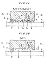
- FIGS. 3A and 3B are views illustrating the manner in which a differential pumping seal apparatus having a differential pumping seal and a hydrostatic bearing according to a second embodiment of the present invention is operated.
- FIG. 3A shows the differential pumping seal which is in operation
- FIG. 3B shows the differential pumping seal which is not in operation.
- reference numeral 8' represents a seal member of a back up seal mechanism 7'.
- the seal member 8' is made of an elastic material and has a thin lip on its tip end.
- the differential pumping seal 5 is not in operation, i.e., while the working fluid is not discharged from the hydrostatic bearing 6 (being disconnected from the working fluid supply source), if the relationship between the pressure P0 in the atmospheric region 2 and the pressure V1' in the clean space region 1 is P0 > V1', then the tip end (lip) of the seal member 8' of the back up seal mechanism 7' is brought into close contact with the movable body 4. Specifically, since the force applied to the seal member 8' by a flow of the working fluid discharged from the hydrostatic bearing 6 is eliminated, the tip end (lip) of the seal member 8' is brought into close contact with the movable body 4 under its own elasticity. The atmosphere in the atmospheric region 2 is thus prevented from flowing into the clean space region 1.
- the seal member 8' is made of resin or rubber containing fluorine.
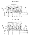
- FIGS. 4A and 4B are views showing the manner in which the differential pumping seal apparatus having the differential pumping seal and the hydrostatic bearing according to the first embodiment of the present invention is operated.
- FIG. 4A shows the differential pumping seal 5 which is in operation
- FIG. 4B shows the differential pumping seal 5 which is not in operation.
- reference numeral 8 represents the seal member of the back up seal mechanism 7, as described above.
- the seal member 8 is movable into and out of the working fluid supply port 7-1 defined in the surface of the partition wall 3 which faces the movable body 4.
- the seal member 8 When the working fluid supply port 7-1 communicates with the evacuating system via the valve (not shown), the seal member 8 is retracted (housed) into the working fluid supply port 7-1, as shown in FIG. 4A.
- the seal member 8 When the working fluid supply port 7-1 communicates with the working fluid supply source via a valve (not shown) and the working fluid is supplied from the working fluid supply source to the working fluid supply port 7-1, the seal member 8 projects from the working fluid supply port 7-1 and is brought into close contact with the movable body 4.
- the working fluid supply port 7-1 of the back up seal mechanism 7 communicates with the evacuating system so that a pressure of V5 is developed in the working fluid supply port 7-1, thus retracting (housing) the seal member 8 into the working fluid supply port 7-1.
- the working fluid supply port 7-1 may be connected to the evacuating system which develops a pressure of V4 in the pump groove 5-3 of the differential pumping seal 5.
- the relationship among the pressure V5 in the working fluid supply port 7-1, the pressure P0 in the atmospheric region 2, and the pressure P1 in the working fluid supply port 6-1 of the hydrostatic bearing 6 is V5 ⁇ P0 ⁇ P1.
- the working fluid supply port 7-1 When the differential pumping seal 5 is not in the normal state, and is not in operation, the working fluid supply port 7-1 is supplied with the working fluid so as to develop a pressure of P3 (P3 > P0) therein, thus projecting the seal member 8 from the working fluid supply port 7-1 and bringing the tip end of the seal member 8 into close contact with the movable body 4.
- the working fluid supply port 7-1 may be connected via a directional-control valve (not shown) to the working fluid supply source which supplies the working fluid to the working fluid supply port 6-1 of the hydrostatic bearing 6, and the directional-control valve may be operated to supply the working fluid from the working fluid supply source to the working fluid supply port 7-1 for thereby allowing the seal member 8 to project.
- a directional-control valve (not shown) to the working fluid supply source which supplies the working fluid to the working fluid supply port 6-1 of the hydrostatic bearing 6, and the directional-control valve may be operated to supply the working fluid from the working fluid supply source to the working fluid supply port 7-1 for thereby allowing the seal member 8 to project.
- the seal member 8 is made of resin or rubber containing fluorine.
- the differential pumping seal apparatus comprises the partition wall 3 which is disposed between the clean space region 1 and the atmospheric region 2, the movable body 4 which is provided so as to pass through the partition wall 3, and the hydrostatic bearing 6 for supporting the movable body 4.
- the present invention is also applicable to a pumping seal apparatus which has a differential pumping seal for sealing the clean space region 1 and the atmospheric region 2 from each other in a non-contact fashion, even if the differential pumping seal apparatus does not have the partition wall 3, the movable body 4, and the hydrostatic bearing 6.
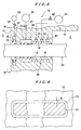
- a differential pumping seal apparatus according to a third embodiment of the present invention will be described below with reference to FIGS. 5 through 7.
- the differential pumping seal apparatus having a differential pumping seal and a hydrostatic bearing will be described below with reference to simplified drawings.
- reference numeral 10 represents the entire structure of the differential pumping seal apparatus
- reference numeral 11 represents a first member which defines a first space 1 serving as a clean space.
- An outer peripheral side of the first member 11 (shown at the left side in FIG. 5) faces a second space, e.g., a second space 2 which is at atmospheric pressure.
- the atmosphere in the second space 2 is different from the atmosphere in the first space 1 (in terms of a pressure, cleanliness, type of a filled gas, and the like).
- a side wall 12 of the first member 11 has a passage 13 which passes therethrough, and the first space 1 and the second space 2 which are defined by the first member 11 communicate with each other through the passage 13.
- a second member 21 is disposed in the passage 13 so as to pass through the passage 13.
- the first member 11 may be a housing which defines the first space 1 (e.g., a vacuum chamber), and the second member 21 may be a slider capable of moving linearly relatively to the housing (in FIGS. 5 and 6). Therefore, hereinafter, the first member will be described as a housing, and the second member as a slider.
- the slider 21 has a rectangular cross section, and hence the passage 13 which accommodates the slider 21 also has a rectangular cross section.
- a gap "g" having a desired dimension ranging, for example, from about 5 to 50 ⁇ m is defined between the slider 21 and the housing 11, so that the slider 21 can be moved without contacting the housing 11.
- the gap "g" is formed on both sides of the housing 11.
- the housing 11 has an inner surface 14 defining the passage 13, and a groove 31 which provides a hydrostatic bearing 30 is formed in the inner surface 14 at a position near the second space 2.
- the groove 31 extends in a circumferential direction of the passage 13 in such a manner that the groove 31 fully surrounds the slider 21. In FIGS. 5 and 6, only upper and lower portions of the groove 31 formed in the inner surface 14 are shown.
- the groove 31 is connected to a supply source 35 for supplying clean air or a clean inert gas via a valve 32, and hence the clean air or the clean inert gas can be supplied from the supply source 35 into the groove 31.
- a plurality of grooves 41 which provide a differential pumping seal 40 is formed in the inner surface 14 at a position between the groove 31 and the first space 1.
- the grooves 41 serving as the differential pumping seal 40 are provided at a position where the slider 21 passes through the housing 11.
- the grooves 41 also extend in a circumferential direction of the passage 13 in such a manner that the grooves 41 fully surround the slider 21.
- FIGS. 5 and 6 only upper and lower portions of the grooves 41 formed in the inner surface 14 are shown.
- the grooves 41 are connected to a vacuum source 45 such as a vacuum container or a vacuum pump via a valve 42, and thus a gas flowing through the gap "g" is evacuated from the grooves 41 by the vacuum source 45.
- the inner surface 14 of the passage 13 further has a groove 51 positioned between the groove 31 of the hydrostatic bearing 30 and the second space 2.
- the groove 51 also extends in a circumferential direction of the passage 13 in such a manner that the groove 51 fully surrounds the slider 21.
- the groove 51 is connected to a supply source 55 for supplying a fluid such as a gas or a liquid via a valve 52, and hence the gas or the liquid can be supplied from the supply source 55 into the groove 51.
- a diaphragm seal member 54 having a substantially U-shaped or V-shaped cross section is disposed in the groove 51, and both side edges of the diaphragm seal member 54 are fixed to an open end of the groove 51 by a known means.
- the diaphragm seal member 54 When no fluid is supplied into the groove 51, the diaphragm seal member 54 is retracted into the groove 51, as shown in FIG. 5.
- the diaphragm seal member 54 is made of resin or rubber containing fluorine, silicon, or butyl acetate.
- the slider 21 is linearly movable in the horizontal direction (to the left or right in FIGS. 5 and 7) in a reciprocating manner by an actuating mechanism (not shown) disposed in the second space 2 under atmospheric pressure. A specimen or the like placed in the first space 1 can be thus moved by the slider 21.
- the valve 32 When the valve 32 is opened to supply the clean air or the clean inert gas from the supply source 35 into the groove 31 of the hydrostatic bearing 30, the clean air or the clean inert gas flows from the groove 31 into the gap "g", thus supporting the slider 21 out of contact with the housing 11 in a non-contact manner. Therefore, the slider 21 can smoothly be reciprocated by the non-illustrated actuating mechanism without contacting the housing 11. Most of the clean air or the clean inert gas which has flowed into the gap "g" flows from the grooves 41 of the differential pumping seal 40 into the vacuum source 45 via the valve 42, and part of the remaining clean air or the remaining clean inert gas flows into the second space 2 under atmospheric pressure.
- the first space 1 which serves as a clean space.
- the first space 1 and the second space 2 are separated from each other by an invisible wall (a non-contact seal, i.e. a differential pumping seal).
- one of the three grooves 41 which is close to the first space 1 may be used as a purge gas port for supplying a purge gas, instead of being used as a groove for discharging the clean air or the clean inert gas.
- the valve 42 of the differential pumping seal apparatus 40 is closed to stop evacuating the clean air or the clean inert gas in the gap "g" from the grooves 41.
- the valve 52 is opened and the fluid is introduced from the supply source 55 into the groove 51. Therefore, as shown in FIG. 7, the diaphragm seal member 54 is deformed in such a manner that a central portion of the diaphragm seal member 54 projects from the groove 51, and is brought into contact with an outer surface 22 of the slider 21.
- the communication between the first space 1 and the second space 2 through the gap "g" is interrupted by the seal member 54.
- the degree of vacuum or the degree of cleanliness in the second space 2 is slightly lowered from the level that is achieved when the differential pumping seal 40 is in operation, but is not lowered enough to obstruct the operation of an apparatus having the differential pumping seal apparatus.
- a highly clean gas may be introduced into the first space 1.
- each of the slider 21 and the passage 13 has a rectangular cross section.
- each of the slider 21 and the passage 13 may have a circular or oval cross section.
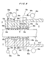
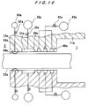
- FIGS. 8 through 11 show a differential pumping seal apparatus according to a fourth embodiment of the present invention.
- Those parts of the differential pumping seal apparatus according to the fourth embodiment which are identical to those of the differential pumping seal apparatus according to the third embodiment are denoted by identical reference numerals with a suffix "a". Structurally and functionally identical parts will not be described in detail below, but only different parts will be described below.
- reference numerals 11a and 11a' represent a first member which serves as a housing defining a first space 1 capable of constituting a clean space
- reference numeral 21a represents a second member which serves as a slider capable of moving (to the left and right in FIG. 8) relatively to the housings 11a and 11a'
- the differential pumping seal apparatus comprises two housings 11a and 11a'.
- the housing 11a is disposed above the slider 21a, and the housing 11a' is disposed below the slider 21a.
- An outer peripheral side of the housing 11a and 11a' (shown at the left side in FIG. 8) faces a second space, e.g., a space 2 which is at atmospheric pressure, and the atmosphere in the space 2 is different from the atmosphere in the first space 1 (in terms of a pressure, cleanliness, type of a filled gas, and the like).
- a hydrostatic bearing and a differential pumping seal which are disposed between the housing 11a and the slider 21a, and a hydrostatic bearing and a differential pumping seal which are disposed between the housing 11a' and the slider 21a are essentially identical in structure to each other. Therefore, only the hydrostatic bearing and the differential pumping seal disposed between the housing 11a and the slider 21a will be described below.
- the housing 11a has a side wall 12a extending annularly (rectangularly in the case where the housing has a rectangular shape, and circularly in the case where the housing has a circular shape) in such a manner that the side wall 12a surrounds the first space 1 above the slider 21a.
- the side wall 12a has a lower surface 14a spaced from the slider 21a by a desired distance over the outer surface of the slider 21a, and a gap "g" between the lower surface 14a and the slider 21a having a desired dimension, e.g., in the range from about 5 to 50 ⁇ m is formed, so that the slider 21a can be moved without contacting the housing 11a.
- the lower surface 14a of the housing 11a has a groove 31a which provides a hydrostatic bearing 30a positioned near the second space 2.
- the groove 31a extends in a track-like (loop-like) shape such as a rectangle, an oval or a circle so that the groove 31a fully surrounds the first space 1.
- the shape of the groove 31a depends on the shape of the first space 1. In FIG. 8, only a portion of the groove 31a is shown.
- the groove 31a is connected to a supply source 35a for supplying clean air or a clean inert gas via a valve 32a, and hence the clean air or the clean inert gas can be supplied from the supply source 35a into the groove 31a.
- the lower surface 14a also has a plurality of grooves 41a (three in the present embodiment) which provide a differential pumping seal 40a and are formed between the groove 31a and the first space 1.
- the grooves 41a extend in a track-like (loop-like) shape such as a rectangle, an oval or a circle so that the grooves 41a fully surround the first space 1.
- the grooves 41a are connected to a vacuum source 45a such as a vacuum container or a vacuum pump via a valve 42a, and thus a gas flowing through the gap "g" is evacuated from the grooves 41a by the vacuum source 45a.
- a diaphragm seal member 54a is disposed on the lower surface 14a at a position between the groove 31a of the hydrostatic bearing 30a and an outer surface of the side wall 12a. As shown in FIG. 11, the diaphragm seal member 54a extends in a loop-like shape such as a rectangle, an oval or a circle so that the diaphragm seal member 54a fully surrounds the first space 1. Both side edge portions of the diaphragm seal member 54a are fixed to the lower surface 14a by a known means.
- the lower surface 14a has a fluid passage 53a which opens at a substantially central position of the diaphragm seal member 54a.
- the fluid passage 53a is connected to a fluid supply source 55a for supplying a fluid via a valve 52a.
- the diaphragm seal member 54a When no fluid is supplied to the fluid passage 53a, the diaphragm seal member 54a is held in the flat shape and is brought into contact with the lower surface 14a as shown in FIG. 8.
- the diaphragm seal member 54a is made of resin or rubber containing fluorine, silicon, or butyl acetate.
- the operations of the hydrostatic bearing 30a and the differential pumping seal 40a is in the same manner as those of the previous embodiment.
- the valve 32a of the hydrostatic bearing 30a is closed and the supply of the clean air or the clean inert gas into the groove 31a is stopped and/or has been stopped
- the valve 42a of the differential pumping seal 40a is closed, whereby the evacuation of the clean air or the clean inert gas in the gap "g" from the grooves 41a is stopped.
- the valve 52a is opened and the fluid is introduced from the supply source 55a through the fluid passage 53a to the backside of the diaphragm seal member 54a. Therefore, as shown in FIG.
- the diaphragm seal member 54a is deformed in such a manner that the central portion of the diaphragm seal member 54a projects toward the slider 21a and is brought into contact with the outer surface 22a of the slider 21a. Consequently, the communication between the first space 1 and the second space 2 through the gap "g" is interrupted by the diaphragm seal member 54a.
- Other operational details of the differential pumping seal apparatus are identical to those of the differential pumping seal apparatus according to the third embodiment.
- the diaphragm seal member 54a is provided on a portion of the lower surface 14a positioned in the same plane as the lower surface 14a.
- the diaphragm seal member 54a may be provided on a recessed portion of the lower surface 14a having a depth equal to the thickness of the diaphragm seal member 54a, so that the outer surface of the diaphragm seal member 54a and the lower surface 14a are in the same plane.
- the principles of the seal member according to the fourth embodiment may be applied to the differential pumping seal apparatus according to the third embodiment, and the principles of the seal member according to the third embodiment may be applied to the differential pumping seal apparatus according to the fourth embodiment.
- FIG. 13 shows a differential pumping seal apparatus according to a fifth embodiment of the present invention.
- Those parts of the differential pumping seal apparatus according to the fifth embodiment which are identical to those of the differential pumping seal apparatus according to the third embodiment are denoted by identical reference numerals with a suffix "b". Structurally and functionally identical parts will not be described in detail below, and only different parts will be described below.
- reference numeral 11b represents a first member which defines a first space 1 which serves as a clean space.
- An outer peripheral side of the first member 11b faces a second space, e.g., a space 2 which is at atmospheric pressure, and the atmosphere in the space 2 is different from the atmosphere in the first space 1 (in terms of a pressure, cleanliness, type of a filled gas, and the like).
- the housing is disposed at only one side of the slider 21b (above the slider 21b in FIG. 13).
- An actuating mechanism for moving the slider 21b is disposed in the second space 2 so that an object such as a specimen is moved by the slider 21b in the first space 1.
- the housing 11b has a side wall 12b extending annularly (rectangularly in the case where the housing has a rectangular shape, and circularly in the case where the housing has a circular shape) in such a manner that the side wall 12b surrounds the first space 1 above the slider 21b.
- the side wall 12b has a lower surface 14b spaced from the slider 21b by a desired distance over the outer surface of the slider 21b.
- the lower surface 14b of the housing 11b has a groove 31b which provides a hydrostatic bearing 30b and a plurality of grooves 41b (three in the present embodiment) which provide a differential pumping seal 40b in the same manner as the third embodiment.
- a fixed seal member 54b is fixed to the lower surface 14b at a position between the groove 31b of the hydrostatic bearing 30b and the outer peripheral surface of the side wall 12b and projects from the lower surface 14b.
- the fixed seal member 54b is not deformed into contact with the slider 21b by being subjected to a fluid pressure, but is operated in the different manner from the previous embodiments.
- the fixed seal member 54b has a function to be brought into contact with the slider 21b without being subject to a fluid pressure, and hence has a function to be brought into contact with the slider 21b when the slider 21b is pushed toward the housing 11b, as described later on.
- the fixed seal member may comprise O-ring seal having a circular cross-section.
- the fixed seal member may comprise any of various other seal members having a different shape insofar as such seal member has the above function. In FIG. 13, only two fixed seal members 54b are shown as being disposed on the left and right portions of the lower surface 14b.
- the fixed seal member 54b extends in a loop-like shape such as a rectangle, an oval or a circle so that the fixed seal member 54b fully surrounds the first space 1.
- the fixed seal member 54b is made of resin or rubber containing fluorine, silicon, or butyl acetate.
- a push device 60b is disposed below the slider 21b at a position corresponding to a position of the fixed seal member 54b which is spaced from the push device 60b in the direction in which the slider 21b is movable.
- the push device 60b has a plunger 62b elastically biased toward the housing 11b by a spring 61b.
- Rollers 63b are rotatably mounted on the upper end of the plunger 62b by a known means, and is held in contact with the lower surface of the slider 21b. Therefore, the slider 21b is linearly movable in a reciprocating manner to the left or right in FIG. 13, while the slider 21b is being in contact with the rollers 63b.
- the operation of the hydrostatic bearing 30b and the differential pumping seal 40b is in the same manner as those of the differential pumping seal apparatus according to the previous embodiments. Specifically, when the valve 32b is opened and the clean air or the clean inert gas is supplied from the supply source 35b into the groove 31b of the hydrostatic bearing 30b, the clean air or the clean inert gas flows from the groove 31b into the gap "g", thus pushing the slider 21b away from the housing 11b against the urging force of the spring 61b of the push device 60b. The slider 21b is thus held out of contact with the fixed seal member 54b fixed to the lower surface 14b of the housing 11b (in a non-contact manner).
- the slider 21b can smoothly be reciprocated by the non-illustrated actuating mechanism without contacting the housing 11.
- Most of the clean air or the clean inert gas which has flowed into the gap "g" flows from the grooves 41b of the differential pumping seal 40b to the vacuum source 45b via the valve 42b, and part of the remaining clean air or the remaining clean inert gas flows into the second space 2 which is at atmospheric pressure. Therefore, only a trace amount of the clean air or the clean inert gas flows into the first space 1 which serves as a clean space. In this state, the first space 1 and the second space 2 are separated from each other by an invisible wall (a non-contact seal or a differential pumping seal).
- one of the three grooves 41b which is close to the first space 1 may be used as a purge gas port for supplying a purge gas, instead of being used as a groove for discharging the clean air or the clean inert gas.
- valve 42b of the differential pumping seal apparatus 40b is closed to stop discharging the clean air or the clean inert gas in the gap "g" from the grooves 41b. Therefore, the fluid pressure developed in the gap "g” is released, and the slider 21b is pushed toward the housing 11b by the urging force of the spring 61b of the push device 60b, as indicated by the two-dot-and-dash lines in FIG. 13, whereby the upper surface 22b of the slider 21b is brought into close contact with the fixed seal member 54b.
- the communication between the first space 1 and the second space 2 through the gap "g" is interrupted by the fixed seal member 54b.
- the degree of vacuum or the degree of cleanliness in the second space 2 is slightly lowered from the level that is achieved when the differential pumping seal 40b is in operation, but is not lowered enough to obstruct the operation of an apparatus having the differential pumping seal apparatus.
- the differential pumping seal apparatus since the differential pumping seal apparatus has the diaphragm seal member operated by a fluid pressure or the fixed seal member which functions when one member is pushed against the other member by the push devices, an apparatus such as a semiconductor fabrication apparatus having a non-contact seal typified by a differential pumping seal can be trouble-free. Specifically, the cleanliness in the clean space (vacuum chamber) can be maintained when the apparatus is shut off in case of emergency or is brought out of operation, and a vacuum can quickly be achieved after the apparatus is started to operate again.
Applications Claiming Priority (4)
| Application Number | Priority Date | Filing Date | Title |
|---|---|---|---|
| JP2001326738 | 2001-10-24 | ||
| JP2001326738A JP3883836B2 (ja) | 2001-10-24 | 2001-10-24 | 差動排気シール装置 |
| JP2002241878A JP4205913B2 (ja) | 2002-08-22 | 2002-08-22 | 差動排気シール装置 |
| JP2002241878 | 2002-08-22 |
Publications (3)
| Publication Number | Publication Date |
|---|---|
| EP1306592A2 true EP1306592A2 (fr) | 2003-05-02 |
| EP1306592A3 EP1306592A3 (fr) | 2004-12-01 |
| EP1306592B1 EP1306592B1 (fr) | 2007-03-21 |
Family
ID=26624076
Family Applications (1)
| Application Number | Title | Priority Date | Filing Date |
|---|---|---|---|
| EP02023879A Expired - Lifetime EP1306592B1 (fr) | 2001-10-24 | 2002-10-24 | Etanchéité pour pression differentielle avec fluide pompé |
Country Status (3)
| Country | Link |
|---|---|
| US (1) | US7134668B2 (fr) |
| EP (1) | EP1306592B1 (fr) |
| DE (1) | DE60218955T2 (fr) |
Cited By (10)
| Publication number | Priority date | Publication date | Assignee | Title |
|---|---|---|---|---|
| EP1333187A2 (fr) * | 2002-01-31 | 2003-08-06 | Canon Kabushiki Kaisha | Dispositif d'aspiration avec moyens de contrôle d'une garniture à labyrinthe à plusieur étages d'un palier hydrostatique utilisé en vide |
| EP1491954A1 (fr) * | 2003-06-27 | 2004-12-29 | ASML Netherlands B.V. | Ensemble d'étanchéité, appareil de projection lithographique, et méthode de fabrication d'un dispositif |
| WO2005047979A2 (fr) * | 2003-11-06 | 2005-05-26 | Carl Zeiss Smt Ag | Systeme optique |
| EP1635382A1 (fr) * | 2003-06-19 | 2006-03-15 | Nikon Corporation | Dispositif d'exposition et procede permettant de produire un dispositif |
| EP1621783A3 (fr) * | 2004-07-26 | 2007-04-18 | Fanuc Ltd | Structure à coussin d'air et actionneur linéaire utilisant ladite structure à coussin d'air |
| WO2009107063A1 (fr) * | 2008-02-28 | 2009-09-03 | Philips Intellectual Property & Standards Gmbh | Dispositif de réduction de débris avec collecteur à feuille tournant et mécanisme d'entraînement |
| US8035795B2 (en) | 2003-04-11 | 2011-10-11 | Nikon Corporation | Apparatus and method for maintaining immersion fluid in the gap under the protection lens during wafer exchange in an immersion lithography machine |
| US8045136B2 (en) | 2004-02-02 | 2011-10-25 | Nikon Corporation | Stage drive method and stage unit, exposure apparatus, and device manufacturing method |
| USRE43576E1 (en) | 2005-04-08 | 2012-08-14 | Asml Netherlands B.V. | Dual stage lithographic apparatus and device manufacturing method |
| US9176393B2 (en) | 2008-05-28 | 2015-11-03 | Asml Netherlands B.V. | Lithographic apparatus and a method of operating the apparatus |
Families Citing this family (9)
| Publication number | Priority date | Publication date | Assignee | Title |
|---|---|---|---|---|
| DE102007016896A1 (de) * | 2007-04-10 | 2008-10-16 | Jost-Werke Gmbh | Kugelkupplung mit relativbeweglich aufgenommener Dichtung |
| US8465024B2 (en) * | 2007-09-07 | 2013-06-18 | Heerema Marine Contractors Nederland B.V. | Sealing device configured to form an air seal around a pipe |
| DE102009019773B4 (de) * | 2009-04-30 | 2022-03-03 | Friedrich-Schiller-Universität Jena | Verfahren zur Verbesserung der Positioniergenauigkeit von mittels Gaslagerelementen geführten Tischen und Verwendung von Luftlagerelementen mit Dichtsystemen für in Umgebungsatmosphäre geführte Tischsysteme |
| GB0922564D0 (en) * | 2009-12-24 | 2010-02-10 | Edwards Ltd | Pump |
| US8939451B2 (en) * | 2013-03-11 | 2015-01-27 | Varian Semiconductor Equipment Associates, Inc. | Floating high vacuum seal cartridge |
| CN105537970B (zh) * | 2014-10-28 | 2018-07-27 | 东芝机械株式会社 | 机床的引导机构以及机床 |
| JP6559937B2 (ja) * | 2014-10-28 | 2019-08-14 | 東芝機械株式会社 | 油静圧案内機構および工作機械 |
| NL2021948A (en) * | 2017-11-14 | 2019-05-17 | Asml Netherlands Bv | Object stage bearing for lithographic apparatus |
| CN114791016B (zh) * | 2022-03-02 | 2024-03-19 | 湖南华园莱客科技有限公司 | 一种多环套接的空气轴承 |
Citations (5)
| Publication number | Priority date | Publication date | Assignee | Title |
|---|---|---|---|---|
| GB938820A (en) * | 1960-04-07 | 1963-10-09 | Alsacienne Constr Meca | Rotary sealing mechanism |
| US4118042A (en) * | 1977-09-27 | 1978-10-03 | The United States Of America As Represented By The United States Department Of Energy | Air bearing vacuum seal assembly |
| US4191385A (en) * | 1979-05-15 | 1980-03-04 | Fox Wayne L | Vacuum-sealed gas-bearing assembly |
| EP0067239A1 (fr) * | 1981-06-13 | 1982-12-22 | Carl Schenck Ag | Disposition d'échanchéité aux boîtes à labyrinthe pour tiges de piston de cylindres de charge à fluide étant logées hydrostatiquement |
| US4425508A (en) * | 1982-05-07 | 1984-01-10 | Gca Corporation | Electron beam lithographic apparatus |
Family Cites Families (13)
| Publication number | Priority date | Publication date | Assignee | Title |
|---|---|---|---|---|
| US3635532A (en) * | 1969-02-08 | 1972-01-18 | Riv Officine Di Villar Perosa | Hydrostatically supported machine tool slide |
| US3610365A (en) * | 1970-06-17 | 1971-10-05 | Nasa | Air bearing |
| US3947044A (en) * | 1975-07-07 | 1976-03-30 | Bralorne Resources Limited | Secondary sealing device |
| US4627362A (en) * | 1983-06-28 | 1986-12-09 | Kabushiki Kaisha Myotoku | Air sliding device for work pallets or the like |
| US5218896A (en) * | 1986-11-06 | 1993-06-15 | Canon Kabushiki Kaisha | Driving mechanism with gas bearing |
| KR0171600B1 (ko) * | 1990-02-26 | 1999-03-30 | 이노우에 아끼라 | 밀봉장치 |
| DE4028048C2 (de) * | 1990-09-05 | 1994-12-08 | Blohm Voss Ag | Abdichtungsvorrichtung für rotierende Wellen, insbesondere Stevenrohrabdichtung für Schiffspropellerwellen |
| US6126169A (en) * | 1998-01-23 | 2000-10-03 | Nikon Corporation | Air bearing operable in a vacuum region |
| US6086255A (en) * | 1998-07-28 | 2000-07-11 | Thompson Industries, Inc. | Hydrostatic bearing and fluid collection system |
| US6287004B1 (en) * | 1999-11-22 | 2001-09-11 | Nikon Corporation | Fluid bearing operable in a vacuum region |
| US6443618B1 (en) * | 2000-07-24 | 2002-09-03 | Moore Epitaxial, Inc. | Particulate free air bearing and seal |
| US6789804B2 (en) * | 2001-07-23 | 2004-09-14 | Kaydon Corporation | Dry gas shutdown seal |
| GB0202468D0 (en) * | 2002-02-02 | 2002-03-20 | Crane John Uk Ltd | Seals |
-
2002
- 2002-10-23 US US10/278,020 patent/US7134668B2/en not_active Expired - Fee Related
- 2002-10-24 EP EP02023879A patent/EP1306592B1/fr not_active Expired - Lifetime
- 2002-10-24 DE DE60218955T patent/DE60218955T2/de not_active Expired - Fee Related
Patent Citations (5)
| Publication number | Priority date | Publication date | Assignee | Title |
|---|---|---|---|---|
| GB938820A (en) * | 1960-04-07 | 1963-10-09 | Alsacienne Constr Meca | Rotary sealing mechanism |
| US4118042A (en) * | 1977-09-27 | 1978-10-03 | The United States Of America As Represented By The United States Department Of Energy | Air bearing vacuum seal assembly |
| US4191385A (en) * | 1979-05-15 | 1980-03-04 | Fox Wayne L | Vacuum-sealed gas-bearing assembly |
| EP0067239A1 (fr) * | 1981-06-13 | 1982-12-22 | Carl Schenck Ag | Disposition d'échanchéité aux boîtes à labyrinthe pour tiges de piston de cylindres de charge à fluide étant logées hydrostatiquement |
| US4425508A (en) * | 1982-05-07 | 1984-01-10 | Gca Corporation | Electron beam lithographic apparatus |
Cited By (65)
| Publication number | Priority date | Publication date | Assignee | Title |
|---|---|---|---|---|
| EP1333187A3 (fr) * | 2002-01-31 | 2010-07-07 | Canon Kabushiki Kaisha | Dispositif d'aspiration avec moyens de contrôle d'une garniture à labyrinthe à plusieur étages d'un palier hydrostatique utilisé en vide |
| EP1333187A2 (fr) * | 2002-01-31 | 2003-08-06 | Canon Kabushiki Kaisha | Dispositif d'aspiration avec moyens de contrôle d'une garniture à labyrinthe à plusieur étages d'un palier hydrostatique utilisé en vide |
| US8351019B2 (en) | 2003-04-11 | 2013-01-08 | Nikon Corporation | Apparatus and method for maintaining immersion fluid in the gap under the projection lens during wafer exchange in an immersion lithography machine |
| US9946163B2 (en) | 2003-04-11 | 2018-04-17 | Nikon Corporation | Apparatus and method for maintaining immersion fluid in the gap under the projection lens during wafer exchange in an immersion lithography machine |
| US8879047B2 (en) | 2003-04-11 | 2014-11-04 | Nikon Corporation | Apparatus and method for maintaining immersion fluid in the gap under the projection lens using a pad member or second stage during wafer exchange in an immersion lithography machine |
| US8848168B2 (en) | 2003-04-11 | 2014-09-30 | Nikon Corporation | Apparatus and method for maintaining immersion fluid in the gap under the projection lens during wafer exchange in an immersion lithography machine |
| US8848166B2 (en) | 2003-04-11 | 2014-09-30 | Nikon Corporation | Apparatus and method for maintaining immersion fluid in the gap under the projection lens during wafer exchange in an immersion lithography machine |
| US9081298B2 (en) | 2003-04-11 | 2015-07-14 | Nikon Corporation | Apparatus for maintaining immersion fluid in the gap under the projection lens during wafer exchange using a co-planar member in an immersion lithography machine |
| US8634057B2 (en) | 2003-04-11 | 2014-01-21 | Nikon Corporation | Apparatus and method for maintaining immersion fluid in the gap under the projection lens during wafer exchange in an immersion lithography machine |
| US8488100B2 (en) | 2003-04-11 | 2013-07-16 | Nikon Corporation | Apparatus and method for maintaining immersion fluid in the gap under the projection lens during wafer exchange in an immersion lithography machine |
| US8610875B2 (en) | 2003-04-11 | 2013-12-17 | Nikon Corporation | Apparatus and method for maintaining immersion fluid in the gap under the projection lens during wafer exchange in an immersion lithography machine |
| US9329493B2 (en) | 2003-04-11 | 2016-05-03 | Nikon Corporation | Apparatus and method for maintaining immersion fluid in the gap under the projection lens during wafer exchange in an immersion lithography machine |
| US9500960B2 (en) | 2003-04-11 | 2016-11-22 | Nikon Corporation | Apparatus and method for maintaining immersion fluid in the gap under the projection lens during wafer exchange in an immersion lithography machine |
| US8514367B2 (en) | 2003-04-11 | 2013-08-20 | Nikon Corporation | Apparatus and method for maintaining immersion fluid in the gap under the projection lens during wafer exchange in an immersion lithography machine |
| US8035795B2 (en) | 2003-04-11 | 2011-10-11 | Nikon Corporation | Apparatus and method for maintaining immersion fluid in the gap under the protection lens during wafer exchange in an immersion lithography machine |
| US8269944B2 (en) | 2003-04-11 | 2012-09-18 | Nikon Corporation | Apparatus and method for maintaining immersion fluid in the gap under the projection lens during wafer exchange in an immersion lithography machine |
| US8027027B2 (en) | 2003-06-19 | 2011-09-27 | Nikon Corporation | Exposure apparatus, and device manufacturing method |
| US7486385B2 (en) | 2003-06-19 | 2009-02-03 | Nikon Corporation | Exposure apparatus, and device manufacturing method |
| US8319941B2 (en) | 2003-06-19 | 2012-11-27 | Nikon Corporation | Exposure apparatus, and device manufacturing method |
| US9810995B2 (en) | 2003-06-19 | 2017-11-07 | Nikon Corporation | Exposure apparatus and device manufacturing method |
| US9001307B2 (en) | 2003-06-19 | 2015-04-07 | Nikon Corporation | Exposure apparatus and device manufacturing method |
| US8436978B2 (en) | 2003-06-19 | 2013-05-07 | Nikon Corporation | Exposure apparatus, and device manufacturing method |
| US10191388B2 (en) | 2003-06-19 | 2019-01-29 | Nikon Corporation | Exposure apparatus, and device manufacturing method |
| US10007188B2 (en) | 2003-06-19 | 2018-06-26 | Nikon Corporation | Exposure apparatus and device manufacturing method |
| EP1635382A4 (fr) * | 2003-06-19 | 2008-01-30 | Nikon Corp | Dispositif d'exposition et procede permettant de produire un dispositif |
| EP1635382A1 (fr) * | 2003-06-19 | 2006-03-15 | Nikon Corporation | Dispositif d'exposition et procede permettant de produire un dispositif |
| US8018575B2 (en) | 2003-06-19 | 2011-09-13 | Nikon Corporation | Exposure apparatus, and device manufacturing method |
| US7812925B2 (en) | 2003-06-19 | 2010-10-12 | Nikon Corporation | Exposure apparatus, and device manufacturing method |
| US8436979B2 (en) | 2003-06-19 | 2013-05-07 | Nikon Corporation | Exposure apparatus, and device manufacturing method |
| US8830445B2 (en) | 2003-06-19 | 2014-09-09 | Nikon Corporation | Exposure apparatus, and device manufacturing method |
| US8692976B2 (en) | 2003-06-19 | 2014-04-08 | Nikon Corporation | Exposure apparatus, and device manufacturing method |
| US8705001B2 (en) | 2003-06-19 | 2014-04-22 | Nikon Corporation | Exposure apparatus, and device manufacturing method |
| US9274437B2 (en) | 2003-06-19 | 2016-03-01 | Nikon Corporation | Exposure apparatus and device manufacturing method |
| US9551943B2 (en) | 2003-06-19 | 2017-01-24 | Nikon Corporation | Exposure apparatus and device manufacturing method |
| US8717537B2 (en) | 2003-06-19 | 2014-05-06 | Nikon Corporation | Exposure apparatus, and device manufacturing method |
| US8724085B2 (en) | 2003-06-19 | 2014-05-13 | Nikon Corporation | Exposure apparatus, and device manufacturing method |
| US9025129B2 (en) | 2003-06-19 | 2015-05-05 | Nikon Corporation | Exposure apparatus, and device manufacturing method |
| US9019473B2 (en) | 2003-06-19 | 2015-04-28 | Nikon Corporation | Exposure apparatus and device manufacturing method |
| US8767177B2 (en) | 2003-06-19 | 2014-07-01 | Nikon Corporation | Exposure apparatus, and device manufacturing method |
| EP1491954A1 (fr) * | 2003-06-27 | 2004-12-29 | ASML Netherlands B.V. | Ensemble d'étanchéité, appareil de projection lithographique, et méthode de fabrication d'un dispositif |
| US7256863B2 (en) | 2003-06-27 | 2007-08-14 | Asml Netherlands B.V. | Sealing assembly, a lithographic projection apparatus, and a device manufacturing method |
| WO2005047979A2 (fr) * | 2003-11-06 | 2005-05-26 | Carl Zeiss Smt Ag | Systeme optique |
| WO2005047979A3 (fr) * | 2003-11-06 | 2005-09-09 | Zeiss Carl Smt Ag | Systeme optique |
| US8045136B2 (en) | 2004-02-02 | 2011-10-25 | Nikon Corporation | Stage drive method and stage unit, exposure apparatus, and device manufacturing method |
| US9665016B2 (en) | 2004-02-02 | 2017-05-30 | Nikon Corporation | Lithographic apparatus and method having substrate table and sensor table to hold immersion liquid |
| US8724079B2 (en) | 2004-02-02 | 2014-05-13 | Nikon Corporation | Stage drive method and stage unit, exposure apparatus, and device manufacturing method |
| US10139737B2 (en) | 2004-02-02 | 2018-11-27 | Nikon Corporation | Lithographic apparatus and method having substrate and sensor tables |
| US8711328B2 (en) | 2004-02-02 | 2014-04-29 | Nikon Corporation | Stage drive method and stage unit, exposure apparatus, and device manufacturing method |
| US10007196B2 (en) | 2004-02-02 | 2018-06-26 | Nikon Corporation | Lithographic apparatus and method having substrate and sensor tables |
| US8705002B2 (en) | 2004-02-02 | 2014-04-22 | Nikon Corporation | Stage drive method and stage unit, exposure apparatus, and device manufacturing method |
| US8553203B2 (en) | 2004-02-02 | 2013-10-08 | Nikon Corporation | Stage drive method and stage unit, exposure apparatus, and device manufacturing method |
| US8547528B2 (en) | 2004-02-02 | 2013-10-01 | Nikon Corporation | Stage drive method and stage unit, exposure apparatus, and device manufacturing method |
| US9684248B2 (en) | 2004-02-02 | 2017-06-20 | Nikon Corporation | Lithographic apparatus having substrate table and sensor table to measure a patterned beam |
| US9632431B2 (en) | 2004-02-02 | 2017-04-25 | Nikon Corporation | Lithographic apparatus and method having substrate and sensor tables |
| US8736808B2 (en) | 2004-02-02 | 2014-05-27 | Nikon Corporation | Stage drive method and stage unit, exposure apparatus, and device manufacturing method |
| EP1621783A3 (fr) * | 2004-07-26 | 2007-04-18 | Fanuc Ltd | Structure à coussin d'air et actionneur linéaire utilisant ladite structure à coussin d'air |
| USRE44446E1 (en) | 2005-04-08 | 2013-08-20 | Asml Netherlands B.V. | Dual stage lithographic apparatus and device manufacturing method |
| USRE43576E1 (en) | 2005-04-08 | 2012-08-14 | Asml Netherlands B.V. | Dual stage lithographic apparatus and device manufacturing method |
| USRE46933E1 (en) | 2005-04-08 | 2018-07-03 | Asml Netherlands B.V. | Dual stage lithographic apparatus and device manufacturing method |
| USRE45576E1 (en) | 2005-04-08 | 2015-06-23 | Asml Netherlands B.V. | Dual stage lithographic apparatus and device manufacturing method |
| USRE47943E1 (en) | 2005-04-08 | 2020-04-14 | Asml Netherlands B.V. | Dual stage lithographic apparatus and device manufacturing method |
| US8338797B2 (en) | 2008-02-28 | 2012-12-25 | Koninklijke Philips Electronics N.V. | Debris mitigation device with rotating foil trap and drive assembly |
| WO2009107063A1 (fr) * | 2008-02-28 | 2009-09-03 | Philips Intellectual Property & Standards Gmbh | Dispositif de réduction de débris avec collecteur à feuille tournant et mécanisme d'entraînement |
| US9176393B2 (en) | 2008-05-28 | 2015-11-03 | Asml Netherlands B.V. | Lithographic apparatus and a method of operating the apparatus |
| US11187991B2 (en) | 2008-05-28 | 2021-11-30 | Asml Netherlands B.V. | Lithographic apparatus and a method of operating the apparatus |
Also Published As
| Publication number | Publication date |
|---|---|
| US7134668B2 (en) | 2006-11-14 |
| EP1306592B1 (fr) | 2007-03-21 |
| EP1306592A3 (fr) | 2004-12-01 |
| DE60218955D1 (de) | 2007-05-03 |
| DE60218955T2 (de) | 2007-11-29 |
| US20030075871A1 (en) | 2003-04-24 |
Similar Documents
| Publication | Publication Date | Title |
|---|---|---|
| EP1306592B1 (fr) | Etanchéité pour pression differentielle avec fluide pompé | |
| US8807914B2 (en) | Seal device and method for operating the same and substrate processing apparatus comprising a vacuum chamber | |
| US7278444B2 (en) | Valve assembly having improved pump-down performance | |
| US6932111B2 (en) | Gate valve apparatus | |
| JP2011166101A (ja) | 真空制御システムおよび真空制御方法 | |
| JP5081986B2 (ja) | 真空システム用のシャッタおよびゲートバルブアセンブリ | |
| EP0062060B1 (fr) | Vanne anti-retour | |
| US6954009B2 (en) | Positioning apparatus | |
| US8308440B2 (en) | Vacuum processing apparatus, method of controlling vacuum processing apparatus, device manufacturing method, and storage medium | |
| JP4205913B2 (ja) | 差動排気シール装置 | |
| JP5261545B2 (ja) | 真空制御システムおよび真空制御方法 | |
| JP2018066370A (ja) | 気密性真空ポンプ遮断弁 | |
| KR101634420B1 (ko) | 진공 제어 시스템 및 진공 제어 방법 | |
| KR101909686B1 (ko) | 게이트 밸브의 구동장치 | |
| JP3883836B2 (ja) | 差動排気シール装置 | |
| JP2006046489A (ja) | 真空用ゲート弁 | |
| KR101436402B1 (ko) | 진공 공정용 러핑밸브 | |
| KR101758802B1 (ko) | 게이트 밸브의 프로텍션 장치 | |
| JP2006234085A (ja) | 真空バルブ | |
| JP4470201B2 (ja) | ゲートバルブ | |
| KR101459012B1 (ko) | 진공 공정용 러핑밸브 | |
| KR101699423B1 (ko) | 러핑 기능을 갖는 진공 공정용 밸브 | |
| JPS61171905A (ja) | エアシリンダの制御装置 | |
| JPH08166085A (ja) | 真空バルブ | |
| JP2933514B2 (ja) | 真空高圧室シール手段 |
Legal Events
| Date | Code | Title | Description |
|---|---|---|---|
| PUAI | Public reference made under article 153(3) epc to a published international application that has entered the european phase |
Free format text: ORIGINAL CODE: 0009012 |
|
| AK | Designated contracting states |
Designated state(s): AT BE BG CH CY CZ DE DK EE ES FI FR GB GR IE IT LI LU MC NL PT SE SK TR |
|
| AX | Request for extension of the european patent |
Extension state: AL LT LV MK RO SI |
|
| PUAL | Search report despatched |
Free format text: ORIGINAL CODE: 0009013 |
|
| AK | Designated contracting states |
Kind code of ref document: A3 Designated state(s): AT BE BG CH CY CZ DE DK EE ES FI FR GB GR IE IT LI LU MC NL PT SE SK TR |
|
| AX | Request for extension of the european patent |
Extension state: AL LT LV MK RO SI |
|
| RIC1 | Information provided on ipc code assigned before grant |
Ipc: 7F 16C 29/02 B Ipc: 7F 16J 15/40 A Ipc: 7F 16C 32/06 B |
|
| 17P | Request for examination filed |
Effective date: 20050531 |
|
| AKX | Designation fees paid |
Designated state(s): DE GB |
|
| GRAP | Despatch of communication of intention to grant a patent |
Free format text: ORIGINAL CODE: EPIDOSNIGR1 |
|
| GRAS | Grant fee paid |
Free format text: ORIGINAL CODE: EPIDOSNIGR3 |
|
| GRAA | (expected) grant |
Free format text: ORIGINAL CODE: 0009210 |
|
| AK | Designated contracting states |
Kind code of ref document: B1 Designated state(s): DE GB |
|
| REG | Reference to a national code |
Ref country code: GB Ref legal event code: FG4D |
|
| REF | Corresponds to: |
Ref document number: 60218955 Country of ref document: DE Date of ref document: 20070503 Kind code of ref document: P |
|
| PLBE | No opposition filed within time limit |
Free format text: ORIGINAL CODE: 0009261 |
|
| STAA | Information on the status of an ep patent application or granted ep patent |
Free format text: STATUS: NO OPPOSITION FILED WITHIN TIME LIMIT |
|
| 26N | No opposition filed |
Effective date: 20071227 |
|
| PGFP | Annual fee paid to national office [announced via postgrant information from national office to epo] |
Ref country code: DE Payment date: 20081029 Year of fee payment: 7 |
|
| PGFP | Annual fee paid to national office [announced via postgrant information from national office to epo] |
Ref country code: GB Payment date: 20081016 Year of fee payment: 7 |
|
| PG25 | Lapsed in a contracting state [announced via postgrant information from national office to epo] |
Ref country code: DE Free format text: LAPSE BECAUSE OF NON-PAYMENT OF DUE FEES Effective date: 20100501 |
|
| PG25 | Lapsed in a contracting state [announced via postgrant information from national office to epo] |
Ref country code: GB Free format text: LAPSE BECAUSE OF NON-PAYMENT OF DUE FEES Effective date: 20091024 |