EP1306922A2 - Antenna structure, methof of using antenna structure and communication device - Google Patents
Antenna structure, methof of using antenna structure and communication device Download PDFInfo
- Publication number
- EP1306922A2 EP1306922A2 EP02023695A EP02023695A EP1306922A2 EP 1306922 A2 EP1306922 A2 EP 1306922A2 EP 02023695 A EP02023695 A EP 02023695A EP 02023695 A EP02023695 A EP 02023695A EP 1306922 A2 EP1306922 A2 EP 1306922A2
- Authority
- EP
- European Patent Office
- Prior art keywords
- antenna
- housing part
- folded
- cellular phone
- phone terminal
- Prior art date
- Legal status (The legal status is an assumption and is not a legal conclusion. Google has not performed a legal analysis and makes no representation as to the accuracy of the status listed.)
- Withdrawn
Links
Images


Classifications
-
- H—ELECTRICITY
- H01—ELECTRIC ELEMENTS
- H01Q—ANTENNAS, i.e. RADIO AERIALS
- H01Q1/00—Details of, or arrangements associated with, antennas
- H01Q1/12—Supports; Mounting means
- H01Q1/22—Supports; Mounting means by structural association with other equipment or articles
- H01Q1/24—Supports; Mounting means by structural association with other equipment or articles with receiving set
-
- H—ELECTRICITY
- H01—ELECTRIC ELEMENTS
- H01Q—ANTENNAS, i.e. RADIO AERIALS
- H01Q9/00—Electrically-short antennas having dimensions not more than twice the operating wavelength and consisting of conductive active radiating elements
- H01Q9/04—Resonant antennas
- H01Q9/0407—Substantially flat resonant element parallel to ground plane, e.g. patch antenna
- H01Q9/0421—Substantially flat resonant element parallel to ground plane, e.g. patch antenna with a shorting wall or a shorting pin at one end of the element
-
- H—ELECTRICITY
- H01—ELECTRIC ELEMENTS
- H01Q—ANTENNAS, i.e. RADIO AERIALS
- H01Q1/00—Details of, or arrangements associated with, antennas
- H01Q1/08—Means for collapsing antennas or parts thereof
-
- H—ELECTRICITY
- H01—ELECTRIC ELEMENTS
- H01Q—ANTENNAS, i.e. RADIO AERIALS
- H01Q1/00—Details of, or arrangements associated with, antennas
- H01Q1/12—Supports; Mounting means
- H01Q1/22—Supports; Mounting means by structural association with other equipment or articles
- H01Q1/24—Supports; Mounting means by structural association with other equipment or articles with receiving set
- H01Q1/241—Supports; Mounting means by structural association with other equipment or articles with receiving set used in mobile communications, e.g. GSM
- H01Q1/242—Supports; Mounting means by structural association with other equipment or articles with receiving set used in mobile communications, e.g. GSM specially adapted for hand-held use
- H01Q1/243—Supports; Mounting means by structural association with other equipment or articles with receiving set used in mobile communications, e.g. GSM specially adapted for hand-held use with built-in antennas
-
- H—ELECTRICITY
- H01—ELECTRIC ELEMENTS
- H01Q—ANTENNAS, i.e. RADIO AERIALS
- H01Q1/00—Details of, or arrangements associated with, antennas
- H01Q1/36—Structural form of radiating elements, e.g. cone, spiral, umbrella; Particular materials used therewith
- H01Q1/362—Structural form of radiating elements, e.g. cone, spiral, umbrella; Particular materials used therewith for broadside radiating helical antennas
-
- H—ELECTRICITY
- H01—ELECTRIC ELEMENTS
- H01Q—ANTENNAS, i.e. RADIO AERIALS
- H01Q21/00—Antenna arrays or systems
- H01Q21/29—Combinations of different interacting antenna units for giving a desired directional characteristic
Definitions
- the present invention relates to an antenna structure used in a communication device, such as a folding cellular phone terminal, a method of using the antenna structure and the communication device.
- Figure 19 shows a configuration of an internal antenna of a conventional cellular phone terminal.
- Figure 19 (a) is a schematic perspective view of the internal antenna of the conventional cellular phone terminal
- Figure 19(b) is a side view thereof.
- an antenna element 1201 is to send or receive radio wave from the cellular phone terminal or from another cellular phone terminal
- a shielding case 1206 and a radio circuit for communication 1207 housed in the shielding case 1206 are disposed on a substrate 1202.
- An LCD 1203 is to display information processed in the cellular phone terminal.
- the antenna element 1201 is supplied with power from a feeding point 1204 on the substrate 1202 and has an end electrically connected to a part of the substrate 1202 via a conductive connection 1205.
- the part of the substrate 1202 and the shielding case 1206 are electrically connected to each other and form a bottom board of the antenna element 1201.
- the antenna element 1201, the part of the substrate 1202 and the shielding case 1206 constitutes the internal antenna.
- Such a cellular phone terminal has gone beyond serving as a telephone and has been transformed to data terminal equipment that enables transmission of e-mails, browsing of WWW web pages or the like. Thus, upsizing of the display thereof is being promoted.
- the folding cellular phone terminal has become popular because it is considered to be suitable for downsizing and display upsizing.
- the folding cellular phone terminal includes a whip antenna, in addition to the internal antenna.
- the internal antenna and the whip antenna are used when the cellular phone terminal is folded and when it is not folded, respectively.
- the impedances of the antennas differ according to whether the cellular phone is folded or not.
- the internal antenna and the whip antenna are adjusted to accommodate the difference in impedance, so that the folding cellular phone terminal has a good antenna characteristic both when it is folded and when it is not folded.
- Figures 20(a)-20(b) show configurations of parts of the folding cellular phone terminal associated with the internal antenna.
- Figure 20 (a) is a front view of the folding cellular phone terminal and
- Figure 20(b) is a side view thereof.
- the folding cellular phone terminal has an upper housing 102 and a lower housing 103 coupled with each other by a hinge part 104, and is configured so that the upper housing 102 can be folded on the lower housing 103 via the hinge part 104.
- a display 109 is incorporated in the upper housing 102, an upper bottom board 207 is incorporated in the housing at the back side of the display 109, and an upper internal antenna element 205 is incorporated in the housing on a side of the upper bottom board 207 opposite to the display 109.
- the whip antenna is inconvenient because it needs to be drawn from the housing when the folding cellular phone is used and needs to be retracted into the housing after use. And, the whip antenna has a problem in that such drawing and retraction may cause damage thereto.
- the folding cellular phone terminal has problems in that the whip antenna is burdensome because it needs to be drawn and retracted and that the whip antenna is susceptible to damage due to such operations.
- the upper internal antenna element 205, the upper bottom board 207 and the lower bottom board 208 constitute the upper internal antenna.
- the upper bottom board 207 and the lower bottom board 208 are electrically connected to each other and serve as a bottom board of the upper internal antenna.
- the antenna bottom board constituted by the upper bottom board 207 and the lower bottom board 208 is also folded. Therefore, the length of the bottom board is about half of that at the time when the cellular phone terminal 201 is not folded. In this case, if the upper bottom board 207 is shorter than a quarter of a wavelength , there is no current standing wave on the bottom board for a desired frequency band, and thus, the bottom board less contributes to radiation of the radio wave from the antenna.
- the antenna needs to have such a wide-band characteristic as to accommodate the difference in the impedance between the cases where it is folded and where it is not folded and the difference in the contribution of the bottom board to the radiation.
- the antenna of the folding cellular phone terminal needs to have a good characteristic both when the cellular phone terminal is folded and when it is not folded, the upper internal antenna becomes large, and in particular, is increased in thickness.
- folding portable radio terminals including the folding cellular phone terminal have a problem in that they becomes thick if the internal antenna is used.
- an object of the present invention is to provide an antenna structure, a method of using the antenna structure and a communication device that eliminate the need to draw and retract an antenna when a folding portable radio terminal is to be used.
- an object of the present invention is to provide an antenna structure, a method of using the antenna structure and a communication device that enable the folding cellular phone terminal to be further slimmed.
- the 1st invention of the present invention is an antenna structure used in a folding portable radio terminal, comprising:
- the 2nd invention of the present invention is the antenna structure according to the 1st invention, wherein when said portable radio terminal is not folded, a diversity reception is carried out with said first antenna serving as a main antenna and said second antenna serving as a sub-antenna, and when said portable radio terminal is folded, a diversity reception is carried out with said first antenna serving as a sub-antenna and said second antenna serving as a main antenna .
- the 3rd invention of the present invention is the antenna structure according to the 1st invention, wherein when said portable radio terminal is not folded, a diversity transmission is carried out with said first antenna serving as a main antenna and said second antenna serving as a sub-antenna, and when said portable radio terminal is folded, a diversity transmission is carried out with said first antenna serving as a sub-antenna and said second antenna serving as a main antenna.
- the 4th invention of the present invention is the antenna structure according to the 1st invention, wherein said first antenna has a better characteristic when said portable radio terminal is not folded, and said second antenna has a better characteristic when said portable radio terminal is folded.
- the 5th invention of the present invention is the antenna structure according to the 1st invention, further comprising:
- the 6th invention of the present invention is the antenna structure according to the 5th invention, wherein said first antenna is an internal antenna incorporated in said first housing part, and said second antenna is an internal antenna incorporated in said second housing part.
- the 7th invention of the present invention is the antenna structure according to the 5th invention, wherein said first antenna comprises an antenna element and a bottom board for said antenna element.
- the 8th invention of the present invention is the antenna structure according to the 1st invention, wherein one of said first and second antennas, which is not used, serves as a passive element for the other, which is used.
- the 9th invention of the present invention is the antenna structure according to the 8th invention, wherein when said first housing part and said second housing part are folded on each other, for reception, diversity reception is carried out at said first antenna and said second antenna, and for transmission, said second antenna is used with said first antenna serving as the passive element, and when said first housing part and said second housing part are not folded on each other, for reception, diversity reception is carried out at said first antenna and said second antenna, and for transmission, one of said first and second antennas which has a higher reception level is used with the other , which has a lower reception level, serving as the passive element.
- the 10th invention of the present invention is the antenna structure according to the 8th invention, wherein when said first housing part and said second housing part are folded on each other, for reception, diversity reception is carried out at said first antenna and said second antenna, and for transmission, one of said first and second antennas which has a higher reception level is used with the other, which has a lower reception level, serving as the passive element, and when said first housing part and said second housing part are not folded on each other, for reception, diversity reception is carried out at said first antenna and said second antenna, and for transmission, said first antenna is used with said second antenna serving as the passive element.
- the 11th invention of the present invention is the antenna structure according to the 8th invention, wherein when said first housing part and said second housing part are folded on each other, for reception, diversity reception is carried out at said first antenna and said second antenna, and for transmission, said second antenna is used with said first antenna serving as the passive element, and when said first housing part and said second housing part are not folded on each other, for reception, diversity reception is carried out at said first antenna and said second antenna, and for transmission, said first antenna is used with said second antenna serving as the passive element.
- the 12th invention of the present invention is the antenna structure according to the 8th invention, wherein when said first housing part and said second housing part are folded on each other, for reception, diversity reception is carried out at said first antenna and said second antenna, and for transmission, one of said first and second antennas which has a higher reception level is used with the other, which has a lower reception level, serving as the passive element, and when said first housing part and said second housing part are not folded on each other, for reception, diversity reception is carried out at said first antenna and said second antenna, and for transmission, one of said first and second antennas which has a higher reception level is used with the other , which has a lower reception level, serving as the passive element.
- the 13th invention of the present invention is an antenna structure used in a folding portable radio terminal, comprising:
- the 14th invention of the present invention is the antenna structure according to the 13th invention, wherein for said low frequency band, said first antenna has a better characteristic when said first housing part and said second housing part are not folded on each other, and for said high frequency band, said first antenna has a better characteristic when said first housing part and said second housing part are folded on each other, and for said low frequency band, said second antenna has a better characteristic when said first housing part and said second housing part are folded on each other, and for said high frequency band, said second antenna has a better characteristic when said first housing part and said second housing part are not folded on each other.
- the 15th invention of the present invention is the antenna structure according to the 8th invention, wherein said antenna which is not used has a load adjusted so that said antenna which is used has a predetermined directivity and a wide band frequency characteristic.
- the 16th invention of the present invention is the antenna structure according to the 1st invention, wherein a thickness of each of said first antenna and said second antenna is less than a thickness of said portable radio terminal determined by components thereof other than said first and second antennas.
- the 17th invention of the present invention is the antenna structure according to the 7th or 13th inventions, wherein a part of said first housing part and/or second housing part is conductive, and said conductive part is used as said bottom board.
- the 18th invention of the present invention is the antenna structure according to the 17th invention, wherein a part of said first housing part is not conductive, the part facing said antenna element and extending away from a connection of said first housing part with said second housing part from an end of said antenna element opposite to the connection.
- the 19th invention of the present invention is the antenna structure according to the 17th invention, wherein a part of said first housing part which faces said second antenna when said first housing part and said second housing part are folded on each other is not conductive.
- the 20th invention of the present invention is the antenna structure according to the 1st invention, wherein whole or a part of said first antenna and/or second antenna is filled with a dielectric.
- the 21st invention of the present invention is the antenna structure according to the 7th invention, further comprising:
- the 22nd invention of the present invention is the antenna structure according to the 21st invention, wherein said display includes a display main body, a frame disposed around said display main body and a reflection plate disposed at the back side of a screen of said display main body, and whole or a part of said reflection plate is conductive and serves also as said bottom board.
- the 23rd invention of the present invention is the antenna structure according to the 21st invention, wherein said display includes a display main body and a frame disposed around said display main body, and whole or a part of said frame is conductive and serves also as said bottom board.
- the 24th invention of the present invention is the antenna structure according to the 1st invention, further comprising:
- the 25th invention of the present invention is the antenna structure according to the 24th invention, wherein a part of said first housing part opposite to the side where the display is incorporated is made of a conductive material, and the part of said first housing part made of a conductive material serves also as said first antenna.
- the 26th invention of the present invention is the antenna structure according to the 25th invention, wherein said first housing part has a slit or slot formed in said part made of a conductive material, and said first antenna and said second antenna are used for a high frequency band and a low frequency band.
- the 27th invention of the present invention is a method of using an antenna structure used in a folding portable radio terminal, the antenna structure comprising:
- the 28th invention of the present invention is a method of using an antenna structure, the antenna structure comprising:
- the 29 invention of the present invention is a communication device, comprising:
- the 30th invention of the present invention is a communication device, comprising:
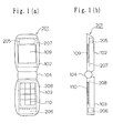
- Figures 1 (a) - (b) show configurations of folding cellular phone terminals 201 according to this embodiment.
- the folding cellular phone terminal 201 has an internal antenna and includes no whip antenna.
- Figure 1 (a) is a front view of the folding cellular phone terminal 201
- Figure 1 (b) is a side view thereof.
- the folding cellular phone terminal 201 has an upper housing 102 and a lower housing 103 coupled with each other by a hinge part 104, and is configured so that the upper housing 102 can be folded on the lower housing 103 via the hinge part 104.
- the upper housing 102 and the lower housing 103 are electrically connected to each other via the hinge part 104.
- a display 109 is incorporated in the upper housing 102, an upper bottom board 207 is incorporated in the housing at the back side of the display 109, and an upper internal antenna element 205 is incorporated in the housing on a side of the upper bottom board 207 opposite to the display 109.
- the upper internal antenna element 205 and the upper bottom board 207 constitute an upper internal antenna.
- the upper internal antenna is adjusted to have a good characteristic both when the folding cellular phone terminal 201 is folded and when it is not folded.
- a key 110 is incorporated in the lower housing 103, and a lower bottom board 208 and a lower internal antenna element 206 are incorporated in the lower housing at the back side of the key 110.
- a microphone (not shown) for voice input is also incorporated in the lower housing 103.
- the lower internal antenna element 206 and the lower bottom board 208 constitute a lower internal antenna.
- the lower internal antenna is adjusted to have a good characteristic both when the folding cellular phone terminal 201 is folded and when it is not folded.
- the cellular phone terminal 201 carries out diversity reception and transmission.
- the upper internal antenna and the lower internal antenna are used for diversity reception. Therefore, the upper internal antenna and the lower internal antenna are each used both when the folding cellular phone terminal 201 is folded and when it is not folded.
- the upper internal antenna and the lower internal antenna are adjusted to have a good characteristic both when the folding cellular phone terminal 201 is folded and when it is not folded, it can relieve an instantaneous signal level drop due to a fading in a multiple transmission environment, so that interception of communication can be avoided.
- the cellular phone terminal 201 since the cellular phone terminal 201 includes no whip antenna, there is no need to draw the whip antenna from the housing of the cellular phone terminal 201 and retract the antenna into the housing each time the cellular phone terminal 201 is used. Thus, the cellular phone terminal 201 is simple to use, and there is no fear of damage to the antenna due to the drawing and retraction thereof.
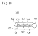
- Figures 2(a)-2(b) show cellular phone terminals 101 according to this embodiment.
- Figure 2(a) is a front view of the cellular phone terminal 101
- Figure 2(b) is a side view thereof.
- the cellular phone terminal 101 is of a folding type, and the antenna thereof is only an internal antenna.
- the cellular phone terminal 101 has an upper housing 102 and a lower housing 103 coupled with each other by a hinge part 104, and is configured so that the upper housing 102 can be folded on the lower housing 103 via the hinge part 104.
- a display 109 is incorporated in the upper housing 102, an upper bottom board 107 is incorporated in the housing at the back side of the display 109, and an upper internal antenna element 105 is incorporated in the housing on a side of the upper bottom board 107 opposite to the display 109.
- the upper internal antenna element 105, the upper bottom board 107 and a lower bottom board 108 constitute an upper internal antenna.
- the upper bottom board 107 and the lower bottom board 108 are electrically connected to each other and serve as a bottom board of the upper internal antenna.
- the upper internal antenna is adjusted to have a good characteristic when the cellular phone terminal 101 is not folded.
- a key 110 is incorporated in the lower housing 103, and the lower bottom board 108 and a lower internal antenna element 106 are incorporated in the lower housing at the back side of the key 110.
- a microphone (not shown) for voice input is also incorporated in the lower housing 103.
- the lower internal antenna element 106, the upper bottom board 107 and the lower bottom board 108 constitute a lower internal antenna.
- the upper bottom board 107 and the lower bottom board 108 are electrically connected to each other and serve as a bottom board of the lower internal antenna.
- the lower internal antenna is adjusted to have a good characteristic when the cellular phone terminal 101 is folded.
- the cellular phone terminal 101 carries out radio communication with abase station, not shown, using a frequency band of 800 MHz-band.
- the upper internal antenna is used. That is, the upper internal antenna is supplied with power.
- the lower internal antenna is used. That is, the lower internal antenna is supplied with power.
- the user of the cellular phone terminal 101 When the cellular phone terminal 101 is used without being folded, the user of the cellular phone terminal 101 generally speaks over the telephone by holding the lower housing 103. At this time, the upper housing 102 is not held by a hand of the user or the like . Therefore, if the cellular phone terminal 101 is used without being folded, the upper internal antenna has a lower gain loss due to the effect of the human body than the lower internal antenna. Therefore, in this case, using the upper internal antenna can further reduce the gain loss due to the effect of the human body.
- the cellular phone terminal 101 when the cellular phone terminal 101 is used with being folded, the user of the cellular phone terminal 101 puts it in a breast pocket or on a desk, table or the like.
- the upper internal antenna since the cellular phone terminal 101 is folded, the upper internal antenna is not used, and the lower internal antenna is used.
- the upper internal antenna serves as a passive element for the lower internal antenna and is arranged to have a predetermined directivity and a wide band frequency characteristic, such a directivity that the intensity of the transmission wave is high in the predetermined direction and the wide band frequency characteristic can be provided.
- Figure 3 (a) shows the cellular phone terminal 101 folded and put in a breast pocket.
- a human breast is shown in a direction of P from the cellular phone terminal. If the lower housing 103 is located near to the human breast and the upper housing 102 is located far from the human breast, such a directivity that a transmission wave having a high intensity in the direction opposite to the breast is emitted can be provided by making the upper internal antenna serve as a passive element and adjusting the load of the passive element. Besides, it can be expected that a wide band frequency characteristic is provided by adjusting the coupling of electromagnetic fields of the upper internal antenna serving as a passive element and the lower internal antenna. Thus, when the cellular phone terminal 101 is put in the breast pocket in a state shown in Figure 3 (a) , the gain loss due to the effect of the human body can be suppressed.
- Figure 3 (b) shows the cellular phone terminal 101 folded and put on a table made of iron.
- the iron table is shown in a direction of Q.
- the upper internal antenna is not used, and the lower internal antenna is used.
- the lower housing 103 is located near to the iron table and the upper housing 102 is located far from the iron table, such a directivity that a transmission wave having a high intensity in the direction opposite to the iron table is emitted can be provided by making the upper internal antenna serve as a passive element and adjusting the load of the passive element.
- a wide band frequency characteristic is provided by adjusting the coupling of electromagnetic fields of the upper internal antenna serving as a passive element and the lower internal antenna.
- the upper internal antenna Since the upper internal antenna is used when the cellular phone terminal 101 is not folded and is not used when the cellular phone terminal 101 is folded, the upper internal antenna needs to be adjusted only to have a good characteristic when the cellular phone terminal 101 is not folded, and there is no need to adjust it to have a good characteristic when the cellular phone terminal 101 is folded.
- the lower internal antenna since the lower internal antenna is used when the cellular phone terminal 101 is folded and is not used when the cellular phone terminal 101 is not folded, the lower internal antenna needs to be adjusted only to have a good characteristic when the cellular phone terminal 101 is folded, and there is no need to adjust it to have a good characteristic when the cellular phone terminal 101 is not folded.
- the upper internal antenna and the lower internal antenna require no conventional sophisticated adjustment, are enhanced in design flexibility, and can be downsized and slimmed. Therefore, a high performance antenna can be provided at a low cost.
- the cellular phone terminal 101 is used with a frequency band of 800 MHz-band. However, it may be used with another frequency band, such as 1.5 GHz-band.
- the upper internal antenna is incorporated in the upper housing 102 and the lower internal antenna is incorporated in the lower housing 103.
- this invention is not limited thereto.
- the two internal antennas may be incorporated in the upper housing 102, or may be incorporated in the lower housing 103. What is essential is that one of the internal antennas is used when the cellular phone terminal is folded, and the other is used when the cellular phone terminal is not folded.
- the lower internal antenna is not used when the cellular phone terminal 101 is not folded and the upper internal antenna is not used when the cellular phone terminal 101 is folded.
- this invention is not limited thereto. If the degradation of the antenna characteristic of the upper internal antenna at the time when the cellular phone terminal 101 is folded compared with that at the time when the cellular phone terminal 101 is not folded is less than the instantaneous signal level variation due to the fading in the multiple transmission environment, it can be expected, of course, that diversity reception at the upper internal antenna and the lower internal antenna relieves the instantaneous signal level drop due to the fading and prevents the communication from being intercepted.
- the degradation of the antenna characteristic of the lower internal antenna at the time when the cellular phone terminal 101 is not folded compared with that at the time when the cellular phone terminal 101 is folded is less than the instantaneous signal level variation due to the fading in the multiple transmission environment, it can be expected, of course, that diversity reception at the upper internal antenna and the lower internal antenna relieves the instantaneous signal level drop due to the fading and prevents the communication from being intercepted.
- the diversity reception may be carried out with the upper internal antenna serving as a main antenna and the lower internal antenna serving as a sub-antenna, and when the cellular phone terminal 101 is folded, the diversity reception may be carried out with the upper internal antenna serving as a sub-antenna and the lower internal antenna serving as a main antenna.
- the diversity transmission may be carried out with the upper internal antenna serving as a main antenna and the lower internal antenna serving as a sub-antenna, and when the cellular phone terminal 101 is folded, the diversity transmission may be carried out with the upper internal antenna serving as a sub-antenna and the lower internal antenna serving as a main antenna.
- the “main antenna” means the antenna normally supplied with power
- the “sub-antenna” means the antenna supplied with power when the reception condition of the main antenna is degraded.
- the “diversity transmission” referred to in this embodiment means that the antenna used as the main antenna during the diversity reception is used as the transmitting antenna during transmission. Therefore, the diversity transmission in this embodiment may be applied to a case where the transmission frequency is different from the reception frequency.
- the diversity reception may carried out with the upper internal antenna with a degraded characteristic and the lower internal antenna with a good characteristic, and for transmission, the transmission wave having a high intensity in a predetermined direction may be emitted by using the lower internal antenna with the upper internal antenna serving as the passive element.
- the diversity reception may carried out with the upper internal antenna with a good characteristic and the lower internal antenna with a degraded characteristic, and for transmission, one of the upper internal antenna and the lower internal antenna which has a higher reception level may be used with the other, which has a lower reception level, serving as the passive element.
- the diversity reception may be carried out with the upper internal antenna and the lower internal antenna, and for transmission, one of the upper internal antenna and the lower internal antenna which has a higher reception level may be used with the other, which has a lower reception level, serving as the passive element.
- the diversity reception may be carried out with the upper internal antenna and the lower internal antenna, and for transmission, the upper internal antenna may be used with the lower internal antenna serving as the passive element.
- the diversity reception may be carried out with the upper internal antenna and the lower internal antenna, and for transmission, the lower internal antenna may be used with the upper internal antenna serving as the passive element.
- the diversity reception may be carried out with the upper internal antenna and the lower internal antenna, and for transmission, the upper internal antenna may be used with the lower internal antenna serving as the passive element.
- the diversity reception may be carried out with the upper internal antenna and the lower internal antenna, and for transmission, one of the upper internal antenna and the lower internal antenna which has a higher reception level may be used with the other, which has a lower reception level, serving as the passive element.
- the diversity reception may be carried out with the upper internal antenna and the lower internal antenna, and for transmission, one of the upper internal antenna and the lower internal antenna which has a higher reception level may be used with the other, which has a lower reception level, serving as the passive element.
- Figure 2 shows a cellular phone terminal 101 according to this embodiment.
- the cellular phone terminal 101 according to this embodiment is configured the same as that according to the second embodiment.
- the cellular phone terminal 101 according to the third embodiment is of a dual band type that can be used with two frequency bands of 800 MHz-band and 1.5 GHz-band.
- the third embodiment is the same as the second embodiment.
- the cellular phone terminal 101 carries out radio communication with a base station, not shown, using frequency bands of 800 MHz-band and 1.5 GHz-band.
- the upper internal antenna is used both in the 800 MHz-band and 1.5 GHz-band. That is, the upper internal antenna is supplied with power.
- the lower internal antenna is used both in the 800 MHz-band and 1.5 GHz-band. That is , the lower internal antenna is supplied with power.
- the upper internal antenna and the lower internal antenna are each used in the two frequency bands , it can be expected that the circuit in the cellular phone terminal 101 is scaled down compared with the case where each internal antenna is used in one frequency band.
- Figure 2 shows a cellular phone terminal 101 according to this embodiment.
- the cellular phone terminal 101 according to this embodiment is configured the same as that according to the second embodiment.
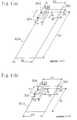
- Figure 4 shows a specific example of the upper internal antenna.
- Figure 4 (a) shows the example of the upper internal antenna at the time when the cellular phone terminal 101 is not folded
- Figure 4(b) shows the example of the upper internal antenna at the time when the cellular phone terminal 101 is folded.
- the upper internal antenna comprises a bottom board 301a, an antenna element 302, a feeding part 303 and a short-circuit part 304.
- the short-circuit part 304 is provided on an end of the bottom board 301a having a length of 140 mm and a width of 40 mm, and the antenna element 302 is supported by the short-circuit part 304 and disposed 5 mm above the bottom board 301a.
- the antenna element 302 is connected to one end of the feeding part 303 for supplying power to the antenna element 302 at a point in an edge thereof to which the short-circuit part 304 is attached and nearer to the center of the bottom board 301a.
- the other end of the feeding part 303 is connected to the bottom board 301a.
- the antenna element 302 has a slit extending in a width direction formed between the short-circuit part 304 and the feeding part 303 on the side thereof to which the short-circuit part 304 and the feeding part 303 are connected. In addition, it has two slits extending in a length direction.
- the upper internal antenna has the slits, the short-circuit part 304 and the feeding part 303 adjusted in their positions to attain matching in the 800 MHz-band.
- the upper internal antenna comprises a bottom board 301b, the antenna element 302, the feeding part 303 and the short-circuit part 304.
- the bottom board 301b of the lower internal antenna shown in Figure 4 (b) has a length of 70 mm and a width of 40mm. The length is shorter than that of the bottom board 301a shown in Figure 4 (a). This is because the upper bottom board 107 and the lower bottom board 108 are folded on each other when the cellular phone terminal 101 is folded. The remainder is the same as Figure 4(a).
- the upper internal antenna is configured as an inverted-F antenna in any case.
- the bottom board 301a is formed by electrically connecting the upper bottom board 107 and the lower bottom board 108, shown in Figure 2, to each other via the hinge part 104 as shown in Figure 4 (a).
- the bottom board 301b is constituted by the upper bottom board 107 and the lower bottom board 108 folded on each other via the hinge part 104, as shown in Figure 4(b).
- FIGS 8 and 9 show an example of the lower internal antenna.
- Figure 8 shows the example of the lower internal antenna in the case where the cellular phone terminal 101 is not folded.
- Figure 8 (a) is a perspective view of the lower internal antenna in the case where the cellular phone terminal 101 is not folded
- Figure 8 (b) shows an antenna element 312 viewed in a direction P in Figure 8(a)
- Figure 8(c) shows the antenna element 312 viewed in a direction Q in Figure 8(a), that is, viewed from above a bottom board 311a.
- the lower internal antenna comprises the grounding bottom board 311a and the antenna element 312. That is, a feeding part 313 is provided on a longitudinal end of the bottom board 311a having a length of 100 mm and a width of 400 mm, and the antenna element 312 is connected to the feeding part 313.
- the antenna element 312 is a helical antenna that is connected to the feeding part 313 and has a spiral shape with bends shown in Figures 8(b) and 8(c).
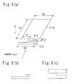
- Figure 9 shows the example of the lower internal antenna in the case where the cellular phone terminal 101 is folded.
- Figure 9(a) is a perspective view of the lower internal antenna in the case where the cellular phone terminal 101 is folded
- Figure 9(b) shows the antenna element 312 viewed in the direction P in Figure 9 (a)
- Figure 9 (c) shows the antenna element 312 viewed in the direction Q in Figure 9(a), that is, viewed from above the bottom board 311b.
- the lower internal antenna comprises the bottom board 311b and the antenna element 312.
- the bottom board 311b is half the length of the bottom board 311a in Figure 8(a).
- the lower internal antenna is configured as a helical antenna in any case.
- the bottom board 311a is formed by electrically connecting the upper bottom board 107 and the lower bottom board 108, shown in Figure 2, to each other via the hinge part 104 as shown in Figure 8 (a).
- the bottom board 311b is constituted by the upper bottom board 107 and the lower bottom board 108 folded on each other via the hinge part 104, as shown in Figure 9(a).
- the upper bottom board 107 and the lower bottom board 108 are electrically connected to each other and form the bottom board 301a shown in Figure 4 (a) or bottom board 311a shown in Figure 8(a) when the cellular phone terminal 101 is not folded.
- the bottom board 301b is constituted by the upper bottom board 107 and the lower bottom board 108 folded on each other via the hinge part 104, as shown in Figure 4(b).
- the bottom board 311b is constituted by the upper bottom board 107 and the lower bottom board 108 folded on each other via the hinge part 104, as shown in Figure 8(b).
- the upper internal antenna is used when the cellular phone terminal 101 is not folded, and the lower internal antenna is used when the cellular phone terminal 101 is folded.
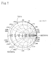
- Figure 5 is a Smith chart showing an impedance characteristic of the upper internal antenna allowing for the part from the feeding part 303 to the antenna element 302 at the time when the cellular phone terminal 101 is not folded.
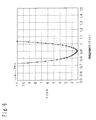
- Figure 6 shows a VSWR (voltage standing wave ratio) thereof.
- the upper internal antenna has a good impedance characteristic in the vicinity of 900 MHz.
- the bandwidth for which the VSWR of the upper internal antenna is 2 or less is 109 MHz.
- the VSWR was 2 or less in the band from 838 MHz to 947 MHz. Therefore, the center frequency of the band for which the VSWR is 2 or less was 893 MHz, and the resonance frequency at which the VSWR is minimized was 900 MHz.
- Figure 7 is a Smith chart showing an impedance characteristic of the upper internal antenna allowing for the part from the feeding part 303 to the antenna element 302 at the time when the cellular phone terminal 101 is folded. Referring to the Smith chart in Figure 7, from 800 MHz to 1 GHz, there is no frequency band that provides a good impedance characteristic.
- the upper internal antenna has a better characteristic when the cellular phone terminal 101 is not folded than when it is folded.
- the upper internal antenna is adjusted to have a better characteristic when the cellular phone terminal 101 is not folded than when it is folded. Therefore, unlike the conventional upper internal antenna, there is no need to adjust the upper internal antenna to have a good characteristic in both states, so that it can be slimmed compared with the conventional upper internal antenna.
- the VSWR thereof allowing for the part from the feeding part 313 to the antenna element 312 was 4.5 at a frequency of 810 MHz and 4.6 at 960 MHz.
- the VSWR thereof allowing for the part from the feeding part 313 to the antenna element 312 was 3.0 at a frequency of 810 MHz and 3.2 at 960 MHz. That is, the lower internal antenna has a better characteristic when the cellular phone terminal 101 is folded than when it is not folded
- the upper internal antenna is used, that is, the upper internal antenna is supplied with power.
- the lower internal antenna is used, that is, the lower internal antenna is supplied with power. In this way, by using the lower internal antenna when the cellular phone terminal 101 is folded and using the upper internal antenna when the cellular phone terminal 101 is not folded, the cellular phone terminal 101 can be slimmed further.
- the upper internal antenna when the upper internal antenna is not used, if the upper internal antenna is made to serve as a passive element for the lower internal antenna and is disposed to have a predetermined directivity and a wide band frequency characteristic, such a directivity that the intensity of the transmission wave is high in the predetermined direction and the wide band frequency characteristic can be provided.
- the lower internal antenna when the lower internal antenna is not used, if the lower internal antenna is made to serve as a passive element for the upper internal antenna and is disposed to have a predetermined directivity and a wide band frequency characteristic, such a directivity that the intensity of the transmission wave is high in the predetermined direction and the wide band frequency characteristic can be provided.
- the strength of the upper internal antenna can be further increased, and the upper internal antenna can be further downsized owing to the wavelength shortening effect of the dielectric.
- the strength of the lower internal antenna can be further increased, and the lower internal antenna can be further downsized owing to the wavelength shortening effect of the dielectric.
- the upper bottom board 107 and the lower bottom board 108 can be constituted by a part of the substrate 1202 and the shielding case 1206 electrically connected to each other.
- a part of the upper housing 102 of the cellular phone terminal 101 may be made of a conductive material, such as a metal part 321, and a part of the lower housing 103 may be made of a conductive material, such as a metal part 322.
- the metal part 321 of the upper housing 102 may be made of a conductive material including a metal, such as magnesium, and the remaining part may be made of resin.
- the metal part 322 of the lower housing 103 may be made of a conductive material including a metal, such as magnesium, and the remaining part may be made of resin. Then, the metal parts 321 and 322 can be made to serve as the bottom board by electrically connecting the upper bottom board 107 to the metal part 321 and the lower bottom board 108 to the metal part 322.
- the SAR is to indicate a degree of the effect of the electromagnetic wave radiated from the cellular phone terminal 101 on a human body tissue. That is, it indicates an amount of absorbed thermal energy per unit tissue, the thermal energy being produced by a high frequency current induced in a quasi-human body by an electromagnetic wave radiated from the cellular phone terminal 101. Therefore, the SAR can be reduced by decreasing the maximum value of the current flowing through the bottom board.
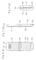
- Figure 11 shows a detailed configuration of the metal parts 321 and 322.
- Figure 11 (a) is a front view of the cellular phone terminal 101 not folded
- Figure 11 (b) is a side view thereof
- Figure 11(c) is a side view of the cellular phone terminal 101 folded.
- the metal part 321 is formed in such a manner that the lower internal antenna element 106 is spaced apart from the metal part 321 when the cellular phone terminal 101 is folded. Therefore, the metal part 321 is formed in such a manner that it does not overlap with the lower internal antenna element 106 when the cellular phone terminal 101 is folded.
- the lower antenna element 106 is configured as a line antenna, such as a helical antenna
- the lower internal antenna can have a wider band by keeping a distance between the lower antenna element 106 and the bottom board.
- the metal part 321 is formed in such a manner that no metal part exists beyond the upper end of the upper internal antenna 105.
- the metal parts 321 and 322 of the upper housing 102 and lower housing 103 to provide the best antenna characteristic, the strength of the cellular phone terminal 101 can be increased, and the antenna can be downsized and shortened.
- the upper bottom board 107 of the upper internal antenna is provided in this embodiment, this invention is not limited thereto and a conductive part of the display 109 may serve also as the upper bottom board 107.
- the reflection plate may be made of a conductive material to serve also as the upper bottom board 107.
- the frame may be made of a conductive material to serve also as the upper bottom board 107.
- whole or a part of the reflection plate, frame and upper housing may serve also as the upper bottom board 107. In such cases, there is no need to provide the upper bottom board 107, and thus, the upper internal antenna can be further shortened.
- the upper internal antenna and the lower internal antenna are each used when the cellular phone terminal is folded or when it is not folded, and therefore, these antennas can be slimmed.
- the upper internal antenna and the lower internal antenna can have a thickness less than that determined by components other than the upper internal antenna and the lower internal antenna in the cellular phone terminal 101. As a result, the cellular phone terminal 101 can be further slimmed.
- Figure 2 shows a cellular phone terminal 101 according to this embodiment.
- the cellular phone terminal 101 according to this embodiment is configured the same as in the second embodiment.
- the cellular phone terminal 101 according to the fifth embodiment is of a dual band type that can be used with two frequency bands of 800 MHz-band and 1.5 GHz-band.
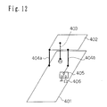
- Figure 12 shows a specific example of the upper internal antenna.
- the upper internal antenna comprises a bottom board 401, an antenna element 402, a feeding part 403, a first short-circuit part 404a, a second short-circuit part 404b and a switch circuit 405.
- first short-circuit part 404a is connected to the bottom board 401
- second short-circuit part 404b is connected to the bottom board 401 via the switch circuit 405.
- the other end of the first short-circuit part 404a and the other end of the second short-circuit part 404b are connected to the antenna element 402.
- One end of the feeding part 403 is connected to the antenna element 402 and the other end thereof is connected to the bottom board 401.
- One terminal of the switch circuit 405 is connected to the bottom board 401 and another terminal thereof is connected to a reactance load 406.
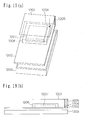
- Figure 13 shows an example of the lower internal antenna.
- an antenna element 412a which is a helical antenna having a spiral shape with bends for the 800 MHz-band
- an antenna element 412b which is a helical antenna having a spiral shape with bends for the 1.5 GHz-band
- the lower internal antenna in Figure 13 is the lower internal antenna shown in Figure 8 additionally provided with the antenna element for the 1.5 GHz-band.
- the lower internal antenna is configured as a helical antenna having a spiral shape with bends in any case.
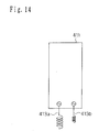
- the lower internal antenna may be one shown in Figure 14.
- the antenna shown in Figure 14 is the same as the antenna shown in Figure 13 except that parts equivalent to the antenna elements 412a and 412b in Figure 13 are in a spiral shape with no bend.
- the bottom board 411 is formed by electrically connecting the upper bottom board 107 and the lower bottom board 108, shown in Figure 2, to each other via the hinge part 104.
- the bottom board 411 is constituted by the upper bottom board 107 and the lower bottom board 108 folded on each other via the hinge part 104.
- the upper bottom board 107 and the lower bottom board 108 are electrically connected to each other and form the bottom board 401 shown in Figure 12 or bottom board 411 shown in Figure 13 when the cellular phone terminal 101 is not folded.
- the bottom board 401 is constituted by the upper bottom board 107 and the lower bottom board 108 folded on each other via the hinge part 104, as shown in Figure 12.
- the bottom board 411 is constituted by the upper bottom board 107 and the lower bottom board 108 folded on each other via the hinge part 104, as shown in Figure 13.
- the upper internal antenna is used when the cellular phone terminal 101 is not folded, and the lower internal antenna is used when the cellular phone terminal 101 is folded.
- the upper internal antenna is used when the cellular phone terminal 101 is folded, and the lower internal antenna is used when the cellular phone terminal 101 is not folded.
- the switch of the upper internal antenna is turned to the reactance load 406, and the upper internal antenna in Figure 12 is used as an inverted-F antenna.
- the switch of the upper internal antenna is turned to the terminal connected to the bottom board 401 to short-circuit the second short-circuit part 404b to the bottom board 401.
- the upper internal antenna in Figure 12 is used as an inverted-F antenna of two-points short-circuit type.
- the antenna element 412a when used in the 800 MHz-band, the antenna element 412a is used by supplying power to the feeding part 413a. And, when used in the 1.5 GHz-band, the antenna element 412b is used by supplying power to the feeding part 413b.
- the upper internal antenna has a better characteristic when the cellular phone terminal 101 is not folded, and in the frequency band of the 1.5 GHz-band, it has a better characteristic when the cellular phone terminal 101 is folded.
- the lower internal antenna has a better characteristic when the cellular phone terminal 101 is folded, and in the frequency band of the 1.5 GHz-band, it has a better characteristic when the cellular phone terminal 101 is not folded.
- the upper internal antenna shown in Figure 12 is used in the 800 MHz-band.
- the bottom board 401 is formed by electrically connecting the upper bottom board 107 and the lower bottom board 108 to each other. Since the bottom board 401 can have a sufficient size, the characteristic thereof can be improved.
- the bottom board 401 is formed by connecting the upper bottom board 107 and the lower bottom board 108 to each other, the bottom board 401 is too large, and thus, the band of the upper internal antenna becomes narrower.
- the upper internal antenna is not used when the cellular phone terminal 101 is not folded, and the upper internal antenna is used only when the cellular phone terminal 101 is folded.
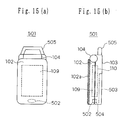
- Figures 15 and 16 show a cellular phone terminal 501 according to a sixth embodiment.
- the cellular phone terminal 501 according to this embodiment is of the folding type as in the embodiments described above.
- Figure 15(a) is a front view of the cellular phone terminal 501 folded, and
- Figure 15(b) is a side view thereof.
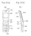
- Figure 16(a) is a front view of the cellular phone terminal 501 not folded, and
- Figure 16 (b) is a side view thereof.
- the cellular phone terminal 501 has an upper housing 102 and a lower housing 103 coupled with each other by a hinge part 104, and is configured so that the upper housing 102 can be folded on the lower housing 103 via the hinge part 104.
- the upper housing 102 has a display 109 incorporated therein and a sound hole 502 for audio output formed therein.
- the back side of the upper housing 102 opposite to the display 109 is made of a metal, such as magnesium, to constitute a housing antenna 102a.
- the housing antenna 102a and the lower bottom board 108 are electrically separated from each other, and the lower bottom board 108 serves as the bottom board of the housing antenna 102a.
- the housing antenna 102a is adjusted to have a good characteristic when the cellular phone terminal 501 is not folded.
- the lower housing 103 has a key 110 incorporated therein, a lower bottom board 108 incorporated therein at the back side of the key 110, and a microphone 504 for audio input incorporated therein on the side of the key 110 opposite to the hinge part 104.
- a boom antenna 505 is disposed on the side of the hinge part 104 opposite to the key 110.
- the lower bottom board 108 serves also as a bottom board of the boom antenna.
- the boom antenna 505 is adjusted to have a good characteristic when the cellular phone terminal 501 is folded.
- the cellular phone terminal 501 carries out radio communication with a base station, not shown, using the frequency band of the 800 MHz-band.
- the housing antenna 102a is used. That is, the housing antenna 102a is supplied with power .
- the boom antenna 505 is used. That is, the boom antenna 505 is supplied with power.
- the housing antenna 102a has a lower gain loss due to the effect of the human body than the boom antenna 505. Therefore, in this case, using the housing antenna 102a can further reduce the gain loss due to the effect of the human body.
- the cellular phone terminal 501 when the cellular phone terminal 501 is used with being folded, the user of the cellular phone terminal 501 puts it in a breast pocket or on a desk, table or the like. In this case, since the cellular phone terminal 501 is folded, the housing antenna 102a is not used, and the boom antenna 505 is used.
- the housing antenna 102a Since the housing antenna 102a is used when the cellular phone terminal 501 is not folded and is not used when the cellular phone terminal 501 is folded, the housing antenna 102a needs to be adjusted only to have a good characteristic when the cellular phone terminal 501 is not folded, and there is no need to adjust it to have a good characteristic when the cellular phone terminal 501 is folded.
- the boom antenna 505 since the boom antenna 505 is used when the cellular phone terminal 501 is folded and is not used when the cellular phone terminal 501 is not folded, the boom antenna 505 needs to be adjusted only to have a good characteristic when the cellular phone terminal 501 is folded, and there is no need to adjust it to have a good characteristic when the cellular phone terminal 501 is not folded.
- the housing antenna 102a and the boom antenna 505 require no conventional sophisticated adjustment, are enhanced in design flexibility, and can be downsized and slimmed. Therefore, a high performance antenna can be provided at a low cost. Furthermore, since a part of the upper housing 102 is made of a metal, such as magnesium, so that the housing antenna 102a serves as the housing and the antenna, there is no need to provide a separate upper antenna element in the upper housing 102, and the upper housing 102 can be shortened accordingly.
- a part of the upper housing on the side of the display 109 may be made of a metal to serve also as an antenna element. If the part of the upper housing on the side of the display 109 may be made of a metal to serve also as an antenna element, the strength of the display 109 can advantageously increased.
- the back side of the upper housing opposite to the display 109 is made of a metal, such as magnesium, to constitute the housing antenna 102a serving as the housing and the antenna as described in this embodiment, the distance between the housing antenna 102a and an ear of the user is increased compared to the case where the part of the upper housing on the side of the display 109 may be made of a metal to serve also as an antenna element. Therefore, a reduced current flows through the ear, so that the effect of the current on the user's body can be reduced.
- the display 109 is made of resin and the holder (frame) of the display 109 is made of a metal, the mechanical strength and stability of the cellular phone terminal 501 can be increased.
- the cellular phone terminal 501 communicates with a base station, not shown with the frequency band of the 800 MHz-band. However, it may be used with two frequency bands of the 800 MHz-band and the 1.5 GHz-band.
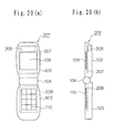
- FIGS 17(a) and 17(b) show housing antennas 102b and 102c, respectively, that can be used with the two frequency bands.
- the housing antenna 102b shown in Figure 17(a) has a slot 506 having a length of about ⁇ /2, where the wavelength for the 1.5 GHz-band is ⁇ .
- the housing antenna 102c shown in Figure 17 (b) has a slit 507 having a length of about ⁇ /4, where the wavelength for the 1.5 GHz-band is ⁇ .
- the housing antennas 102b, 102c can be matched with the radio circuit even if switching between the two frequency bands is done.
- the cellular phone terminal 501 is used with the frequency band of the 800 MHz-band. However, it may be used with another frequency band, such as 1.5 GHz-band.
- the housing antenna is used with the two frequency bands of the 800 MHz-band and the 1.5 GHz-band.
- this embodiment may be applied to a case where it is used with two frequency bands other than the 800 MHz-band and the 1.5 GHz-band.
- the boom antenna 505 is not used when the cellular phone terminal 501 is not folded and the housing antenna 102a is not used when the cellular phone terminal 501 is folded.
- this invention is not limited thereto. If the variation between the characteristic of the boom antenna 505 at the time when the cellular phone terminal 501 is not folded and the characteristic of the housing antenna 102a at the time when the cellular phone terminal 501 is not folded is less than the instantaneous signal level variation due to the fading in the multiple transmission environment, it can be expected, of course, that diversity reception at the housing antenna 102a and the boom antenna 505 relieves the instantaneous signal level drop due to the fading and prevents the communication from being intercepted.
- the variation between the characteristic of the housing antenna 102a at the time when the cellular phone terminal 501 is folded and the characteristic of the boom antenna 505 at the time when the cellular phone terminal 501 is folded is less than the instantaneous signal level variation due to the fading in the multiple transmission environment, it can be expected, of course, that diversity reception at the housing antenna 102a and the boom antenna 505 relieves the instantaneous signal level drop due to the fading and prevents the communication from being intercepted.
- the diversity reception may be carried out with the housing antenna 102a serving as a main antenna and the boom antenna 505 serving as a sub-antenna, and when the cellular phone terminal 501 is folded, the diversity reception may be carried out with the housing antenna 102a serving as a sub-antenna and the boom antenna 505 serving as a main antenna .
- the diversity transmission may be carried out with the housing antenna 102a serving as a main antenna and the boom antenna 505 serving as a sub-antenna
- the diversity transmission may be carried out with the housing antenna 102a serving as a sub-antenna and the boom antenna 505 serving as a main antenna
- the main antenna and the sub-antenna are the same as those described in the first embodiment.
- FIG. 18 is a block diagram showing a communication device 1001 according to this embodiment.
- An example of the communication device 1001 is a cellular phone terminal.
- a transmission signal output from a transmitter circuit is transmitted to a mixer 1003 through a filter 1002.
- the transmission signal input to the mixer 1003 is up-converted with a local signal from an oscilator 1004 and transmitted to an antenna 1009a or 1009b through a transmission filter 1005, an amplifier 1006, a transmission filter 1007 and a switch 1008.
- a reception signal received by the antenna 1009a or 1009b is input to a mixer 1013 via the switch 1008, a reception filter 1010, an amplifier 1011 and a reception filter 1012.
- the reception signal input to the mixer 1013 is down-converted with a local signal from the oscilator 1004 and transmitted to a receiver circuit through a filter 1014.
- the communication device can be shortened.
- the housing antenna and the boom antenna as the antennas 1009a and 1009b, respectively, the communication device can be shortened.
- switch 1008 connected to the antennas 1009a and 1009b, separates the transmission signal and the reception signal in this embodiment, it may be replaced with a duplexer.
- This invention includes the communication device comprising the antenna structure according to this invention, the transmitter circuit that outputs the transmission signal to the first or second antenna, and the receiver circuit that receives the reception signal received by the first or second antenna.
- the antenna can be downsized and slimmed and a slimmed cellular phone terminal can be provided compared to the case where one antenna is configured to exhibit a satisfactory characteristic when the cellular phone terminal is used with being folded and without being folded.
- the upper internal antenna according to this embodiment is an example of a first antenna according to this invention
- the lower internal antenna according to this embodiment is an example of a second antenna according to this invention
- the upper housing according to this embodiment is an example of a first housing part according to this invention
- the lower housing according to this embodiment is an example of a second housing part according to this invention
- the 800 MHz-band in this embodiment is an example of a low frequency band in this invention
- the 1.5 GHz-band in this embodiment is an example of a high frequency band in this invention.
- this invention can provide an antenna structure that enables a folding cellular phone terminal to be slimmed further, a method of using the antenna structure and a communication device.
Abstract
Description
- The present invention relates to an antenna structure used in a communication device, such as a folding cellular phone terminal, a method of using the antenna structure and the communication device.
- Downsizing and slimming of cellular phone terminals are being rapidly advanced. In addition, incorporation of an antenna of a cellular phone terminal into a housing thereof is a world trend.
- Figure 19 shows a configuration of an internal antenna of a conventional cellular phone terminal.
- Figure 19 (a) is a schematic perspective view of the internal antenna of the conventional cellular phone terminal, and Figure 19(b) is a side view thereof. In Figures 19 (a) and 19 (b) , an
antenna element 1201 is to send or receive radio wave from the cellular phone terminal or from another cellular phone terminal, and ashielding case 1206 and a radio circuit forcommunication 1207 housed in theshielding case 1206 are disposed on asubstrate 1202. AnLCD 1203 is to display information processed in the cellular phone terminal. - The
antenna element 1201 is supplied with power from afeeding point 1204 on thesubstrate 1202 and has an end electrically connected to a part of thesubstrate 1202 via aconductive connection 1205. Here, the part of thesubstrate 1202 and theshielding case 1206 are electrically connected to each other and form a bottom board of theantenna element 1201. Thus, theantenna element 1201, the part of thesubstrate 1202 and theshielding case 1206 constitutes the internal antenna. - Such a cellular phone terminal has gone beyond serving as a telephone and has been transformed to data terminal equipment that enables transmission of e-mails, browsing of WWW web pages or the like. Thus, upsizing of the display thereof is being promoted.
- Under such circumstances, the folding cellular phone terminal has become popular because it is considered to be suitable for downsizing and display upsizing.
- Conventionally, the folding cellular phone terminal includes a whip antenna, in addition to the internal antenna. The internal antenna and the whip antenna are used when the cellular phone terminal is folded and when it is not folded, respectively. In general, the impedances of the antennas differ according to whether the cellular phone is folded or not. Thus, the internal antenna and the whip antenna are adjusted to accommodate the difference in impedance, so that the folding cellular phone terminal has a good antenna characteristic both when it is folded and when it is not folded.
- Figures 20(a)-20(b) show configurations of parts of the folding cellular phone terminal associated with the internal antenna. Figure 20 (a) is a front view of the folding cellular phone terminal and Figure 20(b) is a side view thereof.
- The folding cellular phone terminal has an
upper housing 102 and alower housing 103 coupled with each other by ahinge part 104, and is configured so that theupper housing 102 can be folded on thelower housing 103 via thehinge part 104. - A
display 109 is incorporated in theupper housing 102, anupper bottom board 207 is incorporated in the housing at the back side of thedisplay 109, and an upperinternal antenna element 205 is incorporated in the housing on a side of theupper bottom board 207 opposite to thedisplay 109. - However, the whip antenna is inconvenient because it needs to be drawn from the housing when the folding cellular phone is used and needs to be retracted into the housing after use. And, the whip antenna has a problem in that such drawing and retraction may cause damage thereto.
- Thus, the folding cellular phone terminal has problems in that the whip antenna is burdensome because it needs to be drawn and retracted and that the whip antenna is susceptible to damage due to such operations.
- In addition, in the folding cellular phone terminal shown in Figure 20, the upper
internal antenna element 205, theupper bottom board 207 and thelower bottom board 208 constitute the upper internal antenna. In this case, theupper bottom board 207 and thelower bottom board 208 are electrically connected to each other and serve as a bottom board of the upper internal antenna. - When the cellular phone terminal is folded, the antenna bottom board constituted by the
upper bottom board 207 and thelower bottom board 208 is also folded. Therefore, the length of the bottom board is about half of that at the time when thecellular phone terminal 201 is not folded. In this case, if theupper bottom board 207 is shorter than a quarter of a wavelength , there is no current standing wave on the bottom board for a desired frequency band, and thus, the bottom board less contributes to radiation of the radio wave from the antenna. - Therefore, in order to use the upper internal antenna both in the states where the
cellular phone terminal 201 is folded and is not folded, the antenna needs to have such a wide-band characteristic as to accommodate the difference in the impedance between the cases where it is folded and where it is not folded and the difference in the contribution of the bottom board to the radiation. - That is, since the antenna of the folding cellular phone terminal needs to have a good characteristic both when the cellular phone terminal is folded and when it is not folded, the upper internal antenna becomes large, and in particular, is increased in thickness.
- Even if components in the
upper housing 102 except for the upper internal antenna, such asdisplay 109, are reduced in thickness, the thick upper internal antenna prevents theupper housing 102 from being slimmed. Similarly, even if components in thelower housing 103 except for the lower internal antenna are reduced in thickness, the thick lower internal antenna prevents thelower housing 103 from being slimmed. Thus, folding portable radio terminals including the folding cellular phone terminal have a problem in that they becomes thick if the internal antenna is used. - In consideration of the problems described above, an object of the present invention is to provide an antenna structure, a method of using the antenna structure and a communication device that eliminate the need to draw and retract an antenna when a folding portable radio terminal is to be used.
- Furthermore, in consideration of the problems described above, an object of the present invention is to provide an antenna structure, a method of using the antenna structure and a communication device that enable the folding cellular phone terminal to be further slimmed.
- The 1st invention of the present invention is an antenna structure used in a folding portable radio terminal, comprising:
- a first antenna; and
- a second antenna, wherein said first antenna is used at least when said portable radio terminal is not folded, and
-
- The 2nd invention of the present invention is the antenna structure according to the 1st invention, wherein when said portable radio terminal is not folded, a diversity reception is carried out with said first antenna serving as a main antenna and said second antenna serving as a sub-antenna, and
when said portable radio terminal is folded, a diversity reception is carried out with said first antenna serving as a sub-antenna and said second antenna serving as a main antenna . - The 3rd invention of the present invention is the antenna structure according to the 1st invention, wherein when said portable radio terminal is not folded, a diversity transmission is carried out with said first antenna serving as a main antenna and said second antenna serving as a sub-antenna, and
when said portable radio terminal is folded, a diversity transmission is carried out with said first antenna serving as a sub-antenna and said second antenna serving as a main antenna. - The 4th invention of the present invention is the antenna structure according to the 1st invention, wherein said first antenna has a better characteristic when said portable radio terminal is not folded, and
said second antenna has a better characteristic when said portable radio terminal is folded. - The 5th invention of the present invention is the antenna structure according to the 1st invention, further comprising:
- a first housing part that incorporates a speaker of said portable radio terminal therein; and
- a second housing part that incorporates a microphone of said portable radio terminal therein, wherein said first housing part and said second housing part are capable of being folded,
-
- The 6th invention of the present invention is the antenna structure according to the 5th invention, wherein said first antenna is an internal antenna incorporated in said first housing part, and
said second antenna is an internal antenna incorporated in said second housing part. - The 7th invention of the present invention is the antenna structure according to the 5th invention, wherein said first antenna comprises an antenna element and a bottom board for said antenna element.
- The 8th invention of the present invention is the antenna structure according to the 1st invention, wherein one of said first and second antennas, which is not used, serves as a passive element for the other, which is used.
- The 9th invention of the present invention is the antenna structure according to the 8th invention, wherein when said first housing part and said second housing part are folded on each other, for reception, diversity reception is carried out at said first antenna and said second antenna, and for transmission, said second antenna is used with said first antenna serving as the passive element, and
when said first housing part and said second housing part are not folded on each other, for reception, diversity reception is carried out at said first antenna and said second antenna, and for transmission, one of said first and second antennas which has a higher reception level is used with the other , which has a lower reception level, serving as the passive element. - The 10th invention of the present invention is the antenna structure according to the 8th invention, wherein when said first housing part and said second housing part are folded on each other, for reception, diversity reception is carried out at said first antenna and said second antenna, and for transmission, one of said first and second antennas which has a higher reception level is used with the other, which has a lower reception level, serving as the passive element, and
when said first housing part and said second housing part are not folded on each other, for reception, diversity reception is carried out at said first antenna and said second antenna, and for transmission, said first antenna is used with said second antenna serving as the passive element. - The 11th invention of the present invention is the antenna structure according to the 8th invention, wherein when said first housing part and said second housing part are folded on each other, for reception, diversity reception is carried out at said first antenna and said second antenna, and for transmission, said second antenna is used with said first antenna serving as the passive element, and
when said first housing part and said second housing part are not folded on each other, for reception, diversity reception is carried out at said first antenna and said second antenna, and for transmission, said first antenna is used with said second antenna serving as the passive element. - The 12th invention of the present invention is the antenna structure according to the 8th invention, wherein when said first housing part and said second housing part are folded on each other, for reception, diversity reception is carried out at said first antenna and said second antenna, and for transmission, one of said first and second antennas which has a higher reception level is used with the other, which has a lower reception level, serving as the passive element, and
when said first housing part and said second housing part are not folded on each other, for reception, diversity reception is carried out at said first antenna and said second antenna, and for transmission, one of said first and second antennas which has a higher reception level is used with the other , which has a lower reception level, serving as the passive element. - The 13th invention of the present invention is an antenna structure used in a folding portable radio terminal, comprising:
- a first housing part that incorporates a speaker therein;
- a second housing part that incorporates a microphone therein;
- a first antenna; and
- a second antenna, wherein said first housing part and said second housing part are capable of being folded on each other,
-
- The 14th invention of the present invention is the antenna structure according to the 13th invention, wherein for said low frequency band, said first antenna has a better characteristic when said first housing part and said second housing part are not folded on each other, and for said high frequency band, said first antenna has a better characteristic when said first housing part and said second housing part are folded on each other, and
for said low frequency band, said second antenna has a better characteristic when said first housing part and said second housing part are folded on each other, and for said high frequency band, said second antenna has a better characteristic when said first housing part and said second housing part are not folded on each other. - The 15th invention of the present invention is the antenna structure according to the 8th invention, wherein said antenna which is not used has a load adjusted so that said antenna which is used has a predetermined directivity and a wide band frequency characteristic.
- The 16th invention of the present invention is the antenna structure according to the 1st invention, wherein a thickness of each of said first antenna and said second antenna is less than a thickness of said portable radio terminal determined by components thereof other than said first and second antennas.
- The 17th invention of the present invention is the antenna structure according to the 7th or 13th inventions, wherein a part of said first housing part and/or second housing part is conductive, and
said conductive part is used as said bottom board. - The 18th invention of the present invention is the antenna structure according to the 17th invention, wherein a part of said first housing part is not conductive, the part facing said antenna element and extending away from a connection of said first housing part with said second housing part from an end of said antenna element opposite to the connection.
- The 19th invention of the present invention is the antenna structure according to the 17th invention, wherein a part of said first housing part which faces said second antenna when said first housing part and said second housing part are folded on each other is not conductive.
- The 20th invention of the present invention is the antenna structure according to the 1st invention, wherein whole or a part of said first antenna and/or second antenna is filled with a dielectric.
- The 21st invention of the present invention is the antenna structure according to the 7th invention, further comprising:
- a display disposed in said first housing part, wherein said display and said antenna element face each other, and
-
- The 22nd invention of the present invention is the antenna structure according to the 21st invention, wherein said display includes a display main body, a frame disposed around said display main body and a reflection plate disposed at the back side of a screen of said display main body, and
whole or a part of said reflection plate is conductive and serves also as said bottom board. - The 23rd invention of the present invention is the antenna structure according to the 21st invention, wherein said display includes a display main body and a frame disposed around said display main body, and
whole or a part of said frame is conductive and serves also as said bottom board. - The 24th invention of the present invention is the antenna structure according to the 1st invention, further comprising:
- a first housing part that incorporates a speaker of said portable radio terminal; and
- a second housing part that incorporates a microphone of said portable radio terminal, wherein said first housing part serves also as said first antenna, and
-
- The 25th invention of the present invention is the antenna structure according to the 24th invention, wherein a part of said first housing part opposite to the side where the display is incorporated is made of a conductive material, and
the part of said first housing part made of a conductive material serves also as said first antenna. - The 26th invention of the present invention is the antenna structure according to the 25th invention, wherein said first housing part has a slit or slot formed in said part made of a conductive material, and
said first antenna and said second antenna are used for a high frequency band and a low frequency band. - The 27th invention of the present invention is a method of using an antenna structure used in a folding portable radio terminal, the antenna structure comprising:
- a first antenna; and
- a second antenna, wherein said first antenna is used at least when said portable radio terminal is not folded, and
-
- The 28th invention of the present invention is a method of using an antenna structure, the antenna structure comprising:
- a first housing part that incorporates a speaker therein;
- a second housing part that incorporates a microphone therein;
- a first antenna; and
- a second antenna,
- said first housing part and said second housing part being capable of being folded on each other,
- said first antenna including an antenna element and a bottom board,
- said antenna element being disposed in said first housing part, and
- said bottom board being disposed over said first housing part and second housing part, wherein for a low frequency band, said first antenna is used at least when said first housing part and said second housing part are not folded on each other,
-
- The 29 invention of the present invention is a communication device, comprising:
- the antenna structure according to the 1st invention;
- a transmitter circuit that outputs a transmission signal to said first antenna or second antenna; and
- a receiver circuit that receives a reception signal received at said first antenna or second antenna.
-
- The 30th invention of the present invention is a communication device, comprising:
- the antenna structure according to the 13th invention;
- a transmitter circuit that outputs a transmission signal to said first antenna or second antenna; and
- a receiver circuit that receives a reception signal received at said first antenna or second antenna.
-
-
- Figure 1 (a) is a front view of a cellular phone terminal according to a first embodiment of this invention.
- Figure 1(b) is a side view of the cellular phone terminal according to the first embodiment of this invention.
- Figure 2 (a) is a front view of the cellular phone terminal according to second to fourth embodiments of this invention.
- Figure 2 (b) is a side view of the cellular phone terminal according to the second to fourth embodiments of this invention.
- Figure 3(a) illustrates the cellular phone terminal according to the second embodiment of this invention, which is folded and put in a breast pocket.
- Figure 3(b) illustrates the cellular phone terminal according to the second embodiment of this invention, which is folded and put in a table made of iron.
- Figure 4 (a) shows a specific example of an upper internal antenna according to the fourth embodiment of this invention at the time when the cellular phone terminal is not folded.
- Figure 4(b) shows a specific example of the upper internal antenna according to the fourth embodiment of this invention at the time when the cellular phone terminal is folded.
- Figure 5 is a Smith chart for the upper internal antenna according to the fourth embodiment of this invention shown in Figure 4(a).
- Figure 6 shows a frequency characteristic of a VSWR of the upper internal antenna according to the fourth embodiment of this invention shown in Figure 4(a).
- Figure 7 is a Smith chart for the upper internal antenna according to the fourth embodiment of this invention shown in Figure 4(b).
- Figure 8(a) is a perspective view of a lower internal antenna according to the fourth embodiment of this invention at the time when the cellular phone terminal is not folded.
- Figure 8 (b) shows an antenna element of the lower internal antenna according to the fourth embodiment of this invention at the time when the cellular phone terminal is not folded, which is viewed in a direction P.
- Figure 8 (c) shows the antenna element of the lower internal antenna according to the fourth embodiment of this invention at the time when the cellular phone terminal is not folded, which is viewed in a direction Q.
- Figure 9 (a) is a perspective view of the lower internal antenna according to the fourth embodiment of this invention at the time when the cellular phone terminal is folded.
- Figure 9 (b) shows an antenna element of the lower internal antenna according to the fourth embodiment of this invention at the time when the cellular phone terminal is not folded, which is viewed in a direction P.
- Figure 9 (c) shows the antenna element of the lower internal antenna according to the fourth embodiment of this invention at the time when the cellular phone terminal is not folded, which is viewed in a direction Q.
- Figure 10 shows the cellular phone terminal according to the embodiments of this invention with a part of an upper housing and a part of a lower housing being made of a conductive material.
- Figure 11 (a) is a front view of metal parts of the upper housing and lower housing of the cellular phone terminal according to the embodiments of this invention.
- Figure 11(b) is a side view of the metal parts of the upper housing and lower housing of the cellular phone terminal according to the embodiments of this invention.
- Figure 11(c) is a side view of the metal parts of the upper housing and lower housing of the cellular phone terminal according to the embodiments of this invention.
- Figure 12 shows a configuration of the upper internal antenna of the cellular phone terminal according to a fifth embodiment of this invention.
- Figure 13 shows a configuration of the lower internal antenna of the cellular phone terminal according to a fifth embodiment of this invention.
- Figure 14 shows another configuration of the lower internal antenna of the cellular phone terminal according to a fifth embodiment of this invention.
- Figure 15 (a) is a front view of the cellular phone terminal according to a sixth embodiment of this invention at the time when it is folded.
- Figure 15 (b) is a side view of the cellular phone terminal according to the sixth embodiment of this invention at the time when it is folded.
- Figure 16 (a) is a front view of the cellular phone terminal according to the sixth embodiment of this invention at the time when it is not folded.
- Figure 16(b) is a side view of the cellular phone terminal according to the sixth embodiment of this invention at the time when it is not folded.
- Figure 17 (a) is a front view of the cellular phone terminal according to the sixth embodiment of this invention which has a slot formed in a housing antenna thereof.
- Figure 17 (b) is a front view of the cellular phone terminal according to the sixth embodiment of this invention which has a slit formed in a housing antenna thereof.
- Figure 18 is a block diagram showing a configuration of a communication device according to a seventh embodiment of this invention.
- Figure 19(a) is a schematic perspective view of an internal antenna of a conventional cellular phone terminal.
- Figure 19(b) is a schematic side view of the internal antenna of the conventional cellular phone terminal.
- Figure 20 (a) is a front view of the conventional folding cellular phone terminal only having an internal antenna.
- Figure 20(b) is side view of the conventional folding cellular phone terminal only having an internal antenna.
-
-
- 101
- CELLULAR PHONE TERMINAL
- 102
- UPPER HOUSING
- 103
- LOWER HOUSING
- 104
- HINGE PART
- 105
- UPPER INTERNAL ANTENNA ELEMENT
- 106
- LOWER INTERNAL ANTENNA ELEMENT
- 107
- UPPER BOTTOM BOARD
- 108
- LOWER BOTTOM BOARD
- 109
- DISPLAY
- 110
- KEY
- 301a
- BOTTOM BOARD
- 301b
- BOTTOM BOARD
- 302
- ANTENNA ELEMENT
- 303
- FEEDING PART
- 304
- SHORT-CIRCUIT PART
- 311a
- BOTTOM BOARD
- 311b
- BOTTOM BOARD
- 312
- ANTENNA ELEMENT
- Now, embodiments of the present invention will be described with reference to the drawings.
- First, a first embodiment will be described.
- Figures 1 (a) - (b) show configurations of folding
cellular phone terminals 201 according to this embodiment. The foldingcellular phone terminal 201 has an internal antenna and includes no whip antenna. Figure 1 (a) is a front view of the foldingcellular phone terminal 201, and Figure 1 (b) is a side view thereof. - The folding
cellular phone terminal 201 has anupper housing 102 and alower housing 103 coupled with each other by ahinge part 104, and is configured so that theupper housing 102 can be folded on thelower housing 103 via thehinge part 104. Theupper housing 102 and thelower housing 103 are electrically connected to each other via thehinge part 104. - A
display 109 is incorporated in theupper housing 102, anupper bottom board 207 is incorporated in the housing at the back side of thedisplay 109, and an upperinternal antenna element 205 is incorporated in the housing on a side of theupper bottom board 207 opposite to thedisplay 109. - The upper
internal antenna element 205 and theupper bottom board 207 constitute an upper internal antenna. The upper internal antenna is adjusted to have a good characteristic both when the foldingcellular phone terminal 201 is folded and when it is not folded. - A key 110 is incorporated in the
lower housing 103, and alower bottom board 208 and a lowerinternal antenna element 206 are incorporated in the lower housing at the back side of the key 110. In addition, a microphone (not shown) for voice input is also incorporated in thelower housing 103. - The lower
internal antenna element 206 and thelower bottom board 208 constitute a lower internal antenna. The lower internal antenna is adjusted to have a good characteristic both when the foldingcellular phone terminal 201 is folded and when it is not folded. - Then, an operation according to this embodiment will be described.
- The
cellular phone terminal 201 carries out diversity reception and transmission. - That is , the upper internal antenna and the lower internal antenna are used for diversity reception. Therefore, the upper internal antenna and the lower internal antenna are each used both when the folding
cellular phone terminal 201 is folded and when it is not folded. - Since the upper internal antenna and the lower internal antenna are adjusted to have a good characteristic both when the folding
cellular phone terminal 201 is folded and when it is not folded, it can relieve an instantaneous signal level drop due to a fading in a multiple transmission environment, so that interception of communication can be avoided. - Furthermore, since the
cellular phone terminal 201 includes no whip antenna, there is no need to draw the whip antenna from the housing of thecellular phone terminal 201 and retract the antenna into the housing each time thecellular phone terminal 201 is used. Thus, thecellular phone terminal 201 is simple to use, and there is no fear of damage to the antenna due to the drawing and retraction thereof. - Now, a second embodiment will be described.
- Figures 2(a)-2(b) show
cellular phone terminals 101 according to this embodiment. Figure 2(a) is a front view of thecellular phone terminal 101, and Figure 2(b) is a side view thereof. Thecellular phone terminal 101 is of a folding type, and the antenna thereof is only an internal antenna. - The
cellular phone terminal 101 has anupper housing 102 and alower housing 103 coupled with each other by ahinge part 104, and is configured so that theupper housing 102 can be folded on thelower housing 103 via thehinge part 104. - A
display 109 is incorporated in theupper housing 102, anupper bottom board 107 is incorporated in the housing at the back side of thedisplay 109, and an upperinternal antenna element 105 is incorporated in the housing on a side of theupper bottom board 107 opposite to thedisplay 109. The upperinternal antenna element 105, theupper bottom board 107 and alower bottom board 108 constitute an upper internal antenna. In this case, theupper bottom board 107 and thelower bottom board 108 are electrically connected to each other and serve as a bottom board of the upper internal antenna. - The upper internal antenna is adjusted to have a good characteristic when the
cellular phone terminal 101 is not folded. - A key 110 is incorporated in the
lower housing 103, and thelower bottom board 108 and a lowerinternal antenna element 106 are incorporated in the lower housing at the back side of the key 110. In addition, a microphone (not shown) for voice input is also incorporated in thelower housing 103. - The lower
internal antenna element 106, theupper bottom board 107 and thelower bottom board 108 constitute a lower internal antenna. In this case, theupper bottom board 107 and thelower bottom board 108 are electrically connected to each other and serve as a bottom board of the lower internal antenna. - The lower internal antenna is adjusted to have a good characteristic when the
cellular phone terminal 101 is folded. - Then, an operation according to this embodiment will be described.
- The
cellular phone terminal 101 according to this embodiment carries out radio communication with abase station, not shown, using a frequency band of 800 MHz-band. - If the
cellular phone terminal 101 is not folded, the upper internal antenna is used. That is, the upper internal antenna is supplied with power. On the other hand, if thecellular phone terminal 101 is folded, the lower internal antenna is used. That is, the lower internal antenna is supplied with power. - When the
cellular phone terminal 101 is used without being folded, the user of thecellular phone terminal 101 generally speaks over the telephone by holding thelower housing 103. At this time, theupper housing 102 is not held by a hand of the user or the like . Therefore, if thecellular phone terminal 101 is used without being folded, the upper internal antenna has a lower gain loss due to the effect of the human body than the lower internal antenna. Therefore, in this case, using the upper internal antenna can further reduce the gain loss due to the effect of the human body. - On the other hand, when the
cellular phone terminal 101 is used with being folded, the user of thecellular phone terminal 101 puts it in a breast pocket or on a desk, table or the like. In this case, since thecellular phone terminal 101 is folded, the upper internal antenna is not used, and the lower internal antenna is used. Here, in this case, if the upper internal antenna serves as a passive element for the lower internal antenna and is arranged to have a predetermined directivity and a wide band frequency characteristic, such a directivity that the intensity of the transmission wave is high in the predetermined direction and the wide band frequency characteristic can be provided. - Figure 3 (a) shows the
cellular phone terminal 101 folded and put in a breast pocket. In Figure 3(a), a human breast is shown in a direction of P from the cellular phone terminal. If thelower housing 103 is located near to the human breast and theupper housing 102 is located far from the human breast, such a directivity that a transmission wave having a high intensity in the direction opposite to the breast is emitted can be provided by making the upper internal antenna serve as a passive element and adjusting the load of the passive element. Besides, it can be expected that a wide band frequency characteristic is provided by adjusting the coupling of electromagnetic fields of the upper internal antenna serving as a passive element and the lower internal antenna. Thus, when thecellular phone terminal 101 is put in the breast pocket in a state shown in Figure 3 (a) , the gain loss due to the effect of the human body can be suppressed. - Figure 3 (b) shows the
cellular phone terminal 101 folded and put on a table made of iron. In Figure 3(b), the iron table is shown in a direction of Q. In this case, since thecellular phone terminal 101 is folded, the upper internal antenna is not used, and the lower internal antenna is used. If thelower housing 103 is located near to the iron table and theupper housing 102 is located far from the iron table, such a directivity that a transmission wave having a high intensity in the direction opposite to the iron table is emitted can be provided by making the upper internal antenna serve as a passive element and adjusting the load of the passive element. Besides, it can be expected that a wide band frequency characteristic is provided by adjusting the coupling of electromagnetic fields of the upper internal antenna serving as a passive element and the lower internal antenna. Thus, when thecellular phone terminal 101 is put on the table in a state shown in Figure 3 (b) , the gain loss due to the effect of the table can be suppressed. - Since the upper internal antenna is used when the
cellular phone terminal 101 is not folded and is not used when thecellular phone terminal 101 is folded, the upper internal antenna needs to be adjusted only to have a good characteristic when thecellular phone terminal 101 is not folded, and there is no need to adjust it to have a good characteristic when thecellular phone terminal 101 is folded. - Similarly, since the lower internal antenna is used when the
cellular phone terminal 101 is folded and is not used when thecellular phone terminal 101 is not folded, the lower internal antenna needs to be adjusted only to have a good characteristic when thecellular phone terminal 101 is folded, and there is no need to adjust it to have a good characteristic when thecellular phone terminal 101 is not folded. - Therefore, the upper internal antenna and the lower internal antenna require no conventional sophisticated adjustment, are enhanced in design flexibility, and can be downsized and slimmed. Therefore, a high performance antenna can be provided at a low cost.
- In this embodiment described above, the
cellular phone terminal 101 is used with a frequency band of 800 MHz-band. However, it may be used with another frequency band, such as 1.5 GHz-band. - In this embodiment described above, the upper internal antenna is incorporated in the
upper housing 102 and the lower internal antenna is incorporated in thelower housing 103. However, this invention is not limited thereto. The two internal antennas may be incorporated in theupper housing 102, or may be incorporated in thelower housing 103. What is essential is that one of the internal antennas is used when the cellular phone terminal is folded, and the other is used when the cellular phone terminal is not folded. - In this embodiment described above, the lower internal antenna is not used when the
cellular phone terminal 101 is not folded and the upper internal antenna is not used when thecellular phone terminal 101 is folded. However, this invention is not limited thereto. If the degradation of the antenna characteristic of the upper internal antenna at the time when thecellular phone terminal 101 is folded compared with that at the time when thecellular phone terminal 101 is not folded is less than the instantaneous signal level variation due to the fading in the multiple transmission environment, it can be expected, of course, that diversity reception at the upper internal antenna and the lower internal antenna relieves the instantaneous signal level drop due to the fading and prevents the communication from being intercepted. Furthermore, if the degradation of the antenna characteristic of the lower internal antenna at the time when thecellular phone terminal 101 is not folded compared with that at the time when thecellular phone terminal 101 is folded is less than the instantaneous signal level variation due to the fading in the multiple transmission environment, it can be expected, of course, that diversity reception at the upper internal antenna and the lower internal antenna relieves the instantaneous signal level drop due to the fading and prevents the communication from being intercepted. - In this way, when the
cellular phone terminal 101 is not folded, the diversity reception may be carried out with the upper internal antenna serving as a main antenna and the lower internal antenna serving as a sub-antenna, and when thecellular phone terminal 101 is folded, the diversity reception may be carried out with the upper internal antenna serving as a sub-antenna and the lower internal antenna serving as a main antenna. Furthermore, when thecellular phone terminal 101 is not folded, the diversity transmission may be carried out with the upper internal antenna serving as a main antenna and the lower internal antenna serving as a sub-antenna, and when thecellular phone terminal 101 is folded, the diversity transmission may be carried out with the upper internal antenna serving as a sub-antenna and the lower internal antenna serving as a main antenna. - Here, the "main antenna" means the antenna normally supplied with power, and the "sub-antenna" means the antenna supplied with power when the reception condition of the main antenna is degraded. Furthermore, the "diversity transmission" referred to in this embodiment means that the antenna used as the main antenna during the diversity reception is used as the transmitting antenna during transmission. Therefore, the diversity transmission in this embodiment may be applied to a case where the transmission frequency is different from the reception frequency.
- When the
cellular phone terminal 101 is folded, for reception, the diversity reception may carried out with the upper internal antenna with a degraded characteristic and the lower internal antenna with a good characteristic, and for transmission, the transmission wave having a high intensity in a predetermined direction may be emitted by using the lower internal antenna with the upper internal antenna serving as the passive element. And when thecellular phone terminal 101 is not folded, for reception, the diversity reception may carried out with the upper internal antenna with a good characteristic and the lower internal antenna with a degraded characteristic, and for transmission, one of the upper internal antenna and the lower internal antenna which has a higher reception level may be used with the other, which has a lower reception level, serving as the passive element. - When the
cellular phone terminal 101 is folded, for reception, the diversity reception may be carried out with the upper internal antenna and the lower internal antenna, and for transmission, one of the upper internal antenna and the lower internal antenna which has a higher reception level may be used with the other, which has a lower reception level, serving as the passive element. And when thecellular phone terminal 101 is not folded, for reception, the diversity reception may be carried out with the upper internal antenna and the lower internal antenna, and for transmission, the upper internal antenna may be used with the lower internal antenna serving as the passive element. - When the
cellular phone terminal 101 is folded, for reception, the diversity reception may be carried out with the upper internal antenna and the lower internal antenna, and for transmission, the lower internal antenna may be used with the upper internal antenna serving as the passive element. And when thecellular phone terminal 101 is not folded, for reception, the diversity reception may be carried out with the upper internal antenna and the lower internal antenna, and for transmission, the upper internal antenna may be used with the lower internal antenna serving as the passive element. - When the
cellular phone terminal 101 is folded, for reception, the diversity reception may be carried out with the upper internal antenna and the lower internal antenna, and for transmission, one of the upper internal antenna and the lower internal antenna which has a higher reception level may be used with the other, which has a lower reception level, serving as the passive element. And when thecellular phone terminal 101 is not folded, for reception, the diversity reception may be carried out with the upper internal antenna and the lower internal antenna, and for transmission, one of the upper internal antenna and the lower internal antenna which has a higher reception level may be used with the other, which has a lower reception level, serving as the passive element. - Now, a third embodiment will be described.
- Figure 2 shows a
cellular phone terminal 101 according to this embodiment. Thecellular phone terminal 101 according to this embodiment is configured the same as that according to the second embodiment. - Avariation from the second embodiment is that the
cellular phone terminal 101 according to the third embodiment is of a dual band type that can be used with two frequency bands of 800 MHz-band and 1.5 GHz-band. - Except for this, the third embodiment is the same as the second embodiment.
- Now, an operation according to this embodiment will be described primarily with reference to the variation from the second embodiment.
- The
cellular phone terminal 101 according to the third embodiment carries out radio communication with a base station, not shown, using frequency bands of 800 MHz-band and 1.5 GHz-band. - That is , when the
cellular phone terminal 101 is not folded, the upper internal antenna is used both in the 800 MHz-band and 1.5 GHz-band. That is, the upper internal antenna is supplied with power. When thecellular phone terminal 101 is folded, the lower internal antenna is used both in the 800 MHz-band and 1.5 GHz-band. That is , the lower internal antenna is supplied with power. - In this way, also in the case where the two frequency band of 800 MHz-band and 1.5 GHz-band are used, the same effect as the second embodiment can be attained.
- Furthermore, since the upper internal antenna and the lower internal antenna are each used in the two frequency bands , it can be expected that the circuit in the
cellular phone terminal 101 is scaled down compared with the case where each internal antenna is used in one frequency band. - Now, a fourth embodiment will be described.
- Figure 2 shows a
cellular phone terminal 101 according to this embodiment. Thecellular phone terminal 101 according to this embodiment is configured the same as that according to the second embodiment. - Figure 4 shows a specific example of the upper internal antenna.
- Figure 4 (a) shows the example of the upper internal antenna at the time when the
cellular phone terminal 101 is not folded, and Figure 4(b) shows the example of the upper internal antenna at the time when thecellular phone terminal 101 is folded. - When the
cellular phone terminal 101 is not folded, the upper internal antenna comprises abottom board 301a, anantenna element 302, afeeding part 303 and a short-circuit part 304. In the upper internal antenna shown in Figure 4 (a) , the short-circuit part 304 is provided on an end of thebottom board 301a having a length of 140 mm and a width of 40 mm, and theantenna element 302 is supported by the short-circuit part 304 and disposed 5 mm above thebottom board 301a. Theantenna element 302 is connected to one end of thefeeding part 303 for supplying power to theantenna element 302 at a point in an edge thereof to which the short-circuit part 304 is attached and nearer to the center of thebottom board 301a. The other end of thefeeding part 303 is connected to thebottom board 301a. Theantenna element 302 has a slit extending in a width direction formed between the short-circuit part 304 and thefeeding part 303 on the side thereof to which the short-circuit part 304 and thefeeding part 303 are connected. In addition, it has two slits extending in a length direction. Thus, the upper internal antenna has the slits, the short-circuit part 304 and thefeeding part 303 adjusted in their positions to attain matching in the 800 MHz-band. - When the
cellular phone terminal 101 is folded, the upper internal antenna comprises abottom board 301b, theantenna element 302, the feedingpart 303 and the short-circuit part 304. Thebottom board 301b of the lower internal antenna shown in Figure 4 (b) has a length of 70 mm and a width of 40mm. The length is shorter than that of thebottom board 301a shown in Figure 4 (a). This is because theupper bottom board 107 and thelower bottom board 108 are folded on each other when thecellular phone terminal 101 is folded. The remainder is the same as Figure 4(a). - In this way, the upper internal antenna is configured as an inverted-F antenna in any case.
- When the
cellular phone terminal 101 is not folded, thebottom board 301a is formed by electrically connecting theupper bottom board 107 and thelower bottom board 108, shown in Figure 2, to each other via thehinge part 104 as shown in Figure 4 (a). When thecellular phone terminal 101 is folded, thebottom board 301b is constituted by theupper bottom board 107 and thelower bottom board 108 folded on each other via thehinge part 104, as shown in Figure 4(b). - Figures 8 and 9 show an example of the lower internal antenna.
- Figure 8 shows the example of the lower internal antenna in the case where the
cellular phone terminal 101 is not folded. Figure 8 (a) is a perspective view of the lower internal antenna in the case where thecellular phone terminal 101 is not folded, Figure 8 (b) shows anantenna element 312 viewed in a direction P in Figure 8(a) and Figure 8(c) shows theantenna element 312 viewed in a direction Q in Figure 8(a), that is, viewed from above abottom board 311a. - When the
cellular phone terminal 101 is not folded, as shown in Figure 8(a), the lower internal antenna comprises thegrounding bottom board 311a and theantenna element 312. That is, afeeding part 313 is provided on a longitudinal end of thebottom board 311a having a length of 100 mm and a width of 400 mm, and theantenna element 312 is connected to thefeeding part 313. Theantenna element 312 is a helical antenna that is connected to thefeeding part 313 and has a spiral shape with bends shown in Figures 8(b) and 8(c). - Figure 9 shows the example of the lower internal antenna in the case where the
cellular phone terminal 101 is folded. Figure 9(a) is a perspective view of the lower internal antenna in the case where thecellular phone terminal 101 is folded, Figure 9(b) shows theantenna element 312 viewed in the direction P in Figure 9 (a) and Figure 9 (c) shows theantenna element 312 viewed in the direction Q in Figure 9(a), that is, viewed from above thebottom board 311b. - As shown in Figure 9(a), the lower internal antenna comprises the
bottom board 311b and theantenna element 312. Thebottom board 311b is half the length of thebottom board 311a in Figure 8(a). - In this way, the lower internal antenna is configured as a helical antenna in any case.
- When the
cellular phone terminal 101 is not folded, thebottom board 311a is formed by electrically connecting theupper bottom board 107 and thelower bottom board 108, shown in Figure 2, to each other via thehinge part 104 as shown in Figure 8 (a). When thecellular phone terminal 101 is folded, thebottom board 311b is constituted by theupper bottom board 107 and thelower bottom board 108 folded on each other via thehinge part 104, as shown in Figure 9(a). - Now, an operation according to this embodiment will be described.
- According to this embodiment, the
upper bottom board 107 and thelower bottom board 108 are electrically connected to each other and form thebottom board 301a shown in Figure 4 (a) orbottom board 311a shown in Figure 8(a) when thecellular phone terminal 101 is not folded. - On the other hand, when the
cellular phone terminal 101 is folded, thebottom board 301b is constituted by theupper bottom board 107 and thelower bottom board 108 folded on each other via thehinge part 104, as shown in Figure 4(b). When thecellular phone terminal 101 is folded, thebottom board 311b is constituted by theupper bottom board 107 and thelower bottom board 108 folded on each other via thehinge part 104, as shown in Figure 8(b). - In the 800 MHz-band, the upper internal antenna is used when the
cellular phone terminal 101 is not folded, and the lower internal antenna is used when thecellular phone terminal 101 is folded. - The impedance characteristic and VSWR of such an upper internal antenna were measured by experiment. Figure 5 is a Smith chart showing an impedance characteristic of the upper internal antenna allowing for the part from the feeding
part 303 to theantenna element 302 at the time when thecellular phone terminal 101 is not folded. Figure 6 shows a VSWR (voltage standing wave ratio) thereof. As shown in Figure 5, the upper internal antenna has a good impedance characteristic in the vicinity of 900 MHz. Furthermore, as shown in Figure 6, the bandwidth for which the VSWR of the upper internal antenna is 2 or less is 109 MHz. In other words , the VSWR was 2 or less in the band from 838 MHz to 947 MHz. Therefore, the center frequency of the band for which the VSWR is 2 or less was 893 MHz, and the resonance frequency at which the VSWR is minimized was 900 MHz. - Figure 7 is a Smith chart showing an impedance characteristic of the upper internal antenna allowing for the part from the feeding
part 303 to theantenna element 302 at the time when thecellular phone terminal 101 is folded. Referring to the Smith chart in Figure 7, from 800 MHz to 1 GHz, there is no frequency band that provides a good impedance characteristic. - That is, in the 800 MHz-band, the upper internal antenna has a better characteristic when the
cellular phone terminal 101 is not folded than when it is folded. - Thus, the upper internal antenna is adjusted to have a better characteristic when the
cellular phone terminal 101 is not folded than when it is folded. Therefore, unlike the conventional upper internal antenna, there is no need to adjust the upper internal antenna to have a good characteristic in both states, so that it can be slimmed compared with the conventional upper internal antenna. - For the lower internal antenna, when the
cellular phone terminal 101 is not folded, the VSWR thereof allowing for the part from the feedingpart 313 to theantenna element 312 was 4.5 at a frequency of 810 MHz and 4.6 at 960 MHz. On the other hand, when thecellular phone terminal 101 is folded, the VSWR thereof allowing for the part from the feedingpart 313 to theantenna element 312 was 3.0 at a frequency of 810 MHz and 3.2 at 960 MHz. That is, the lower internal antenna has a better characteristic when thecellular phone terminal 101 is folded than when it is not folded - Accordingly, when the
cellular phone terminal 101 is not folded, the upper internal antenna is used, that is, the upper internal antenna is supplied with power. On the other hand, when thecellular phone terminal 101 is folded, the lower internal antenna is used, that is, the lower internal antenna is supplied with power. In this way, by using the lower internal antenna when thecellular phone terminal 101 is folded and using the upper internal antenna when thecellular phone terminal 101 is not folded, thecellular phone terminal 101 can be slimmed further. - In the fourth embodiment, as in the second embodiment, when the upper internal antenna is not used, if the upper internal antenna is made to serve as a passive element for the lower internal antenna and is disposed to have a predetermined directivity and a wide band frequency characteristic, such a directivity that the intensity of the transmission wave is high in the predetermined direction and the wide band frequency characteristic can be provided. Similarly, when the lower internal antenna is not used, if the lower internal antenna is made to serve as a passive element for the upper internal antenna and is disposed to have a predetermined directivity and a wide band frequency characteristic, such a directivity that the intensity of the transmission wave is high in the predetermined direction and the wide band frequency characteristic can be provided.
- In addition, if a space between the
antenna element 302 and thebottom board 301a of the upper internal antenna shown in Figure 4 is filled with a dielectric, the strength of the upper internal antenna can be further increased, and the upper internal antenna can be further downsized owing to the wavelength shortening effect of the dielectric. - Similarly, if a space between the
antenna element 312 and thebottom board 311a of the lower internal antenna shown in Figures 8 and 9 is filled with a dielectric, the strength of the lower internal antenna can be further increased, and the lower internal antenna can be further downsized owing to the wavelength shortening effect of the dielectric. - As in the case of the internal antenna described in the Prior Art, the
upper bottom board 107 and thelower bottom board 108 according to this embodiment can be constituted by a part of thesubstrate 1202 and theshielding case 1206 electrically connected to each other. - Furthermore, as shown in Figure 10, a part of the
upper housing 102 of thecellular phone terminal 101 may be made of a conductive material, such as ametal part 321, and a part of thelower housing 103 may be made of a conductive material, such as ametal part 322. Specifically, themetal part 321 of theupper housing 102 may be made of a conductive material including a metal, such as magnesium, and the remaining part may be made of resin. Similarly, themetal part 322 of thelower housing 103 may be made of a conductive material including a metal, such as magnesium, and the remaining part may be made of resin. Then, themetal parts upper bottom board 107 to themetal part 321 and thelower bottom board 108 to themetal part 322. - This increases the area serving as the bottom board and decreases the maximum value of the current density, so that the SAR (specific absorption ratio) can be further reduced.
- Here, the SAR is to indicate a degree of the effect of the electromagnetic wave radiated from the
cellular phone terminal 101 on a human body tissue. That is, it indicates an amount of absorbed thermal energy per unit tissue, the thermal energy being produced by a high frequency current induced in a quasi-human body by an electromagnetic wave radiated from thecellular phone terminal 101. Therefore, the SAR can be reduced by decreasing the maximum value of the current flowing through the bottom board. - Figure 11 shows a detailed configuration of the
metal parts cellular phone terminal 101 not folded, and Figure 11 (b) is a side view thereof. Figure 11(c) is a side view of thecellular phone terminal 101 folded. Themetal part 321 is formed in such a manner that the lowerinternal antenna element 106 is spaced apart from themetal part 321 when thecellular phone terminal 101 is folded. Therefore, themetal part 321 is formed in such a manner that it does not overlap with the lowerinternal antenna element 106 when thecellular phone terminal 101 is folded. In the case where thelower antenna element 106 is configured as a line antenna, such as a helical antenna, the lower internal antenna can have a wider band by keeping a distance between thelower antenna element 106 and the bottom board. - In addition, the
metal part 321 is formed in such a manner that no metal part exists beyond the upper end of the upperinternal antenna 105. By disposing the upperinternal antenna element 105 at the end of the bottom board, the impedance matching can be readily accomplished and a wide band characteristic can be provided. - In this way, by designing the
metal parts upper housing 102 andlower housing 103 to provide the best antenna characteristic, the strength of thecellular phone terminal 101 can be increased, and the antenna can be downsized and shortened. - While the
upper bottom board 107 of the upper internal antenna is provided in this embodiment, this invention is not limited thereto and a conductive part of thedisplay 109 may serve also as theupper bottom board 107. For example, in the case where thedisplay 109 comprises a display main body, a frame provided around the display main body and a reflection plate provided at the back side of the screen of the display main body, the reflection plate may be made of a conductive material to serve also as theupper bottom board 107. Alternatively, the frame may be made of a conductive material to serve also as theupper bottom board 107. Furthermore, whole or a part of the reflection plate, frame and upper housing may serve also as theupper bottom board 107. In such cases, there is no need to provide theupper bottom board 107, and thus, the upper internal antenna can be further shortened. - As described above, according to this embodiment, the upper internal antenna and the lower internal antenna are each used when the cellular phone terminal is folded or when it is not folded, and therefore, these antennas can be slimmed. Thus , the upper internal antenna and the lower internal antenna can have a thickness less than that determined by components other than the upper internal antenna and the lower internal antenna in the
cellular phone terminal 101. As a result, thecellular phone terminal 101 can be further slimmed. - Now, a fifth embodiment will be described.
- Figure 2 shows a
cellular phone terminal 101 according to this embodiment. Thecellular phone terminal 101 according to this embodiment is configured the same as in the second embodiment. - Avariation from the second embodiment is that the
cellular phone terminal 101 according to the fifth embodiment is of a dual band type that can be used with two frequency bands of 800 MHz-band and 1.5 GHz-band. - Figure 12 shows a specific example of the upper internal antenna.
- The upper internal antenna comprises a
bottom board 401, anantenna element 402, afeeding part 403, a first short-circuit part 404a, a second short-circuit part 404b and aswitch circuit 405. - Specifically, one end of the first short-
circuit part 404a is connected to thebottom board 401, and one end of the second short-circuit part 404b is connected to thebottom board 401 via theswitch circuit 405. The other end of the first short-circuit part 404a and the other end of the second short-circuit part 404b are connected to theantenna element 402. One end of thefeeding part 403 is connected to theantenna element 402 and the other end thereof is connected to thebottom board 401. One terminal of theswitch circuit 405 is connected to thebottom board 401 and another terminal thereof is connected to areactance load 406. - Figure 13 shows an example of the lower internal antenna.
- In the lower internal antenna, an
antenna element 412a, which is a helical antenna having a spiral shape with bends for the 800 MHz-band, is connected to abottom board 411 via afeeding part 413a for the 800 MHz-band, and anantenna element 412b, which is a helical antenna having a spiral shape with bends for the 1.5 GHz-band, is connected to thebottom board 411 via afeeding part 413b for the 1.5 GHz-band. That is, the lower internal antenna in Figure 13 is the lower internal antenna shown in Figure 8 additionally provided with the antenna element for the 1.5 GHz-band. - The lower internal antenna is configured as a helical antenna having a spiral shape with bends in any case.
- The lower internal antenna may be one shown in Figure 14. The antenna shown in Figure 14 is the same as the antenna shown in Figure 13 except that parts equivalent to the
antenna elements - When the
cellular phone terminal 101 is not folded, as in the fourth embodiment, thebottom board 411 is formed by electrically connecting theupper bottom board 107 and thelower bottom board 108, shown in Figure 2, to each other via thehinge part 104. When thecellular phone terminal 101 is folded, thebottom board 411 is constituted by theupper bottom board 107 and thelower bottom board 108 folded on each other via thehinge part 104. - Now, an operation according to this embodiment will be described.
- According to this embodiment, the
upper bottom board 107 and thelower bottom board 108 are electrically connected to each other and form thebottom board 401 shown in Figure 12 orbottom board 411 shown in Figure 13 when thecellular phone terminal 101 is not folded. On the other hand, when thecellular phone terminal 101 is folded, thebottom board 401 is constituted by theupper bottom board 107 and thelower bottom board 108 folded on each other via thehinge part 104, as shown in Figure 12. When thecellular phone terminal 101 is folded, thebottom board 411 is constituted by theupper bottom board 107 and thelower bottom board 108 folded on each other via thehinge part 104, as shown in Figure 13. - In the 800 MHz-band, the upper internal antenna is used when the
cellular phone terminal 101 is not folded, and the lower internal antenna is used when thecellular phone terminal 101 is folded. - On the other hand, in the 1.5GHz-band, the upper internal antenna is used when the
cellular phone terminal 101 is folded, and the lower internal antenna is used when thecellular phone terminal 101 is not folded. - For the 800 MHz-band, the switch of the upper internal antenna is turned to the
reactance load 406, and the upper internal antenna in Figure 12 is used as an inverted-F antenna. On the other hand, for the 1.5 GHz-band, the switch of the upper internal antenna is turned to the terminal connected to thebottom board 401 to short-circuit the second short-circuit part 404b to thebottom board 401. In this way, the upper internal antenna in Figure 12 is used as an inverted-F antenna of two-points short-circuit type. - As for the lower internal antenna, when used in the 800 MHz-band, the
antenna element 412a is used by supplying power to thefeeding part 413a. And, when used in the 1.5 GHz-band, theantenna element 412b is used by supplying power to thefeeding part 413b. - Thus, in the frequency band of the 800 MHz-band, the upper internal antenna has a better characteristic when the
cellular phone terminal 101 is not folded, and in the frequency band of the 1.5 GHz-band, it has a better characteristic when thecellular phone terminal 101 is folded. And, in the frequency band of the 800 MHz-band, the lower internal antenna has a better characteristic when thecellular phone terminal 101 is folded, and in the frequency band of the 1.5 GHz-band, it has a better characteristic when thecellular phone terminal 101 is not folded. - When the
cellular phone terminal 101 is not folded, the upper internal antenna shown in Figure 12 is used in the 800 MHz-band. In this case, thebottom board 401 is formed by electrically connecting theupper bottom board 107 and thelower bottom board 108 to each other. Since thebottom board 401 can have a sufficient size, the characteristic thereof can be improved. For the 1.5 GHz-band, however, if thebottom board 401 is formed by connecting theupper bottom board 107 and thelower bottom board 108 to each other, thebottom board 401 is too large, and thus, the band of the upper internal antenna becomes narrower. Thus, for the 1.5 GHz-band, the upper internal antenna is not used when thecellular phone terminal 101 is not folded, and the upper internal antenna is used only when thecellular phone terminal 101 is folded. - As described above, since a better one can be selected among conditions of the bottom board for each frequency, a wider band and a higher efficiency can be realized.
- Figures 15 and 16 show a
cellular phone terminal 501 according to a sixth embodiment. Thecellular phone terminal 501 according to this embodiment is of the folding type as in the embodiments described above. Figure 15(a) is a front view of thecellular phone terminal 501 folded, and Figure 15(b) is a side view thereof. Figure 16(a) is a front view of thecellular phone terminal 501 not folded, and Figure 16 (b) is a side view thereof. - The
cellular phone terminal 501 has anupper housing 102 and alower housing 103 coupled with each other by ahinge part 104, and is configured so that theupper housing 102 can be folded on thelower housing 103 via thehinge part 104. - The
upper housing 102 has adisplay 109 incorporated therein and asound hole 502 for audio output formed therein. The back side of theupper housing 102 opposite to thedisplay 109 is made of a metal, such as magnesium, to constitute ahousing antenna 102a. In this case, thehousing antenna 102a and thelower bottom board 108 are electrically separated from each other, and thelower bottom board 108 serves as the bottom board of thehousing antenna 102a. - The
housing antenna 102a is adjusted to have a good characteristic when thecellular phone terminal 501 is not folded. - The
lower housing 103 has a key 110 incorporated therein, alower bottom board 108 incorporated therein at the back side of the key 110, and amicrophone 504 for audio input incorporated therein on the side of the key 110 opposite to thehinge part 104. In addition, aboom antenna 505 is disposed on the side of thehinge part 104 opposite to the key 110. Thelower bottom board 108 serves also as a bottom board of the boom antenna. - The
boom antenna 505 is adjusted to have a good characteristic when thecellular phone terminal 501 is folded. - Then, an operation according to this embodiment will be described.
- The
cellular phone terminal 501 according to this embodiment carries out radio communication with a base station, not shown, using the frequency band of the 800 MHz-band. - If the
cellular phone terminal 501 is not folded, thehousing antenna 102a is used. That is, thehousing antenna 102a is supplied with power . On the other hand, if thecellular phone terminal 501 is folded, theboom antenna 505 is used. That is, theboom antenna 505 is supplied with power. - When the
cellular phone terminal 501 is used without being folded, the user of thecellular phone terminal 501 generally speaks over the telephone by holding thelower housing 103. At this time, theupper housing 102 is not held by a hand of the user or the like . Therefore , if thecellular phone terminal 501 is used without being folded, thehousing antenna 102a has a lower gain loss due to the effect of the human body than theboom antenna 505. Therefore, in this case, using thehousing antenna 102a can further reduce the gain loss due to the effect of the human body. - On the other hand, when the
cellular phone terminal 501 is used with being folded, the user of thecellular phone terminal 501 puts it in a breast pocket or on a desk, table or the like. In this case, since thecellular phone terminal 501 is folded, thehousing antenna 102a is not used, and theboom antenna 505 is used. - Since the
housing antenna 102a is used when thecellular phone terminal 501 is not folded and is not used when thecellular phone terminal 501 is folded, thehousing antenna 102a needs to be adjusted only to have a good characteristic when thecellular phone terminal 501 is not folded, and there is no need to adjust it to have a good characteristic when thecellular phone terminal 501 is folded. - Similarly, since the
boom antenna 505 is used when thecellular phone terminal 501 is folded and is not used when thecellular phone terminal 501 is not folded, theboom antenna 505 needs to be adjusted only to have a good characteristic when thecellular phone terminal 501 is folded, and there is no need to adjust it to have a good characteristic when thecellular phone terminal 501 is not folded. - Therefore, the
housing antenna 102a and theboom antenna 505 require no conventional sophisticated adjustment, are enhanced in design flexibility, and can be downsized and slimmed. Therefore, a high performance antenna can be provided at a low cost. Furthermore, since a part of theupper housing 102 is made of a metal, such as magnesium, so that thehousing antenna 102a serves as the housing and the antenna, there is no need to provide a separate upper antenna element in theupper housing 102, and theupper housing 102 can be shortened accordingly. - Alternatively, a part of the upper housing on the side of the
display 109 may be made of a metal to serve also as an antenna element. If the part of the upper housing on the side of thedisplay 109 may be made of a metal to serve also as an antenna element, the strength of thedisplay 109 can advantageously increased. However, if the back side of the upper housing opposite to thedisplay 109 is made of a metal, such as magnesium, to constitute thehousing antenna 102a serving as the housing and the antenna as described in this embodiment, the distance between thehousing antenna 102a and an ear of the user is increased compared to the case where the part of the upper housing on the side of thedisplay 109 may be made of a metal to serve also as an antenna element. Therefore, a reduced current flows through the ear, so that the effect of the current on the user's body can be reduced. - If the back side of the
upper housing 102 is made of a metal, such as magnesium, to constitute thehousing antenna 102a, thedisplay 109 is made of resin and the holder (frame) of thedisplay 109 is made of a metal, the mechanical strength and stability of thecellular phone terminal 501 can be increased. - In this embodiment described above, the
cellular phone terminal 501 communicates with a base station, not shown with the frequency band of the 800 MHz-band. However, it may be used with two frequency bands of the 800 MHz-band and the 1.5 GHz-band. - Figures 17(a) and 17(b) show
housing antennas housing antenna 102b shown in Figure 17(a) has aslot 506 having a length of about λ/2, where the wavelength for the 1.5 GHz-band is λ. Thehousing antenna 102c shown in Figure 17 (b) has aslit 507 having a length of about λ/4, where the wavelength for the 1.5 GHz-band is λ. - In this way, owing to the configuration that enables the
housing antennas cellular phone terminal 501, thehousing antennas - In this embodiment described above, the
cellular phone terminal 501 is used with the frequency band of the 800 MHz-band. However, it may be used with another frequency band, such as 1.5 GHz-band. - In this embodiment described above, the housing antenna is used with the two frequency bands of the 800 MHz-band and the 1.5 GHz-band. However, this embodiment may be applied to a case where it is used with two frequency bands other than the 800 MHz-band and the 1.5 GHz-band.
- In this embodiment described above, the
boom antenna 505 is not used when thecellular phone terminal 501 is not folded and thehousing antenna 102a is not used when thecellular phone terminal 501 is folded. However, this invention is not limited thereto. If the variation between the characteristic of theboom antenna 505 at the time when thecellular phone terminal 501 is not folded and the characteristic of thehousing antenna 102a at the time when thecellular phone terminal 501 is not folded is less than the instantaneous signal level variation due to the fading in the multiple transmission environment, it can be expected, of course, that diversity reception at thehousing antenna 102a and theboom antenna 505 relieves the instantaneous signal level drop due to the fading and prevents the communication from being intercepted. Furthermore, if the variation between the characteristic of thehousing antenna 102a at the time when thecellular phone terminal 501 is folded and the characteristic of theboom antenna 505 at the time when thecellular phone terminal 501 is folded is less than the instantaneous signal level variation due to the fading in the multiple transmission environment, it can be expected, of course, that diversity reception at thehousing antenna 102a and theboom antenna 505 relieves the instantaneous signal level drop due to the fading and prevents the communication from being intercepted. - In this way, when the
cellular phone terminal 501 is not folded, the diversity reception may be carried out with thehousing antenna 102a serving as a main antenna and theboom antenna 505 serving as a sub-antenna, and when thecellular phone terminal 501 is folded, the diversity reception may be carried out with thehousing antenna 102a serving as a sub-antenna and theboom antenna 505 serving as a main antenna . Furthermore , when thecellular phone terminal 501 is not folded, the diversity transmission may be carried out with thehousing antenna 102a serving as a main antenna and theboom antenna 505 serving as a sub-antenna, and when thecellular phone terminal 501 is folded, the diversity transmission may be carried out with thehousing antenna 102a serving as a sub-antenna and theboom antenna 505 serving as a main antenna . Here, the main antenna and the sub-antenna are the same as those described in the first embodiment. - Now, a seventh embodiment will be described. Figure 18 is a block diagram showing a
communication device 1001 according to this embodiment. An example of thecommunication device 1001 is a cellular phone terminal. In Figure 18, a transmission signal output from a transmitter circuit is transmitted to amixer 1003 through afilter 1002. The transmission signal input to themixer 1003 is up-converted with a local signal from anoscilator 1004 and transmitted to anantenna transmission filter 1005, anamplifier 1006, atransmission filter 1007 and aswitch 1008. A reception signal received by theantenna mixer 1013 via theswitch 1008, areception filter 1010, anamplifier 1011 and areception filter 1012. The reception signal input to themixer 1013 is down-converted with a local signal from theoscilator 1004 and transmitted to a receiver circuit through afilter 1014. - Here, by using the upper internal antenna and the lower internal antenna described above in the embodiments as the
antennas antennas - While the
switch 1008, connected to theantennas - This invention includes the communication device comprising the antenna structure according to this invention, the transmitter circuit that outputs the transmission signal to the first or second antenna, and the receiver circuit that receives the reception signal received by the first or second antenna.
- As described above, by using a plurality of antennas each of which exhibits a good characteristic when the cellular phone terminal is used with being folded or without being folded, the antenna can be downsized and slimmed and a slimmed cellular phone terminal can be provided compared to the case where one antenna is configured to exhibit a satisfactory characteristic when the cellular phone terminal is used with being folded and without being folded.
- The upper internal antenna according to this embodiment is an example of a first antenna according to this invention, the lower internal antenna according to this embodiment is an example of a second antenna according to this invention, the upper housing according to this embodiment is an example of a first housing part according to this invention, the lower housing according to this embodiment is an example of a second housing part according to this invention, the 800 MHz-band in this embodiment is an example of a low frequency band in this invention, and the 1.5 GHz-band in this embodiment is an example of a high frequency band in this invention.
- As can be seen from the above description, this invention can provide an antenna structure that enables a folding cellular phone terminal to be slimmed further, a method of using the antenna structure and a communication device.
said second antenna is used at least when said portable radio terminal is folded.
said first antenna is disposed in said first housing part, and
said second antenna is disposed in said second housing part.
said first antenna includes an antenna element and a bottom board for said antenna element,
said antenna element is disposed in said first housing part,
said bottom board is disposed over said first housing part and second housing part,
for a low frequency band, said first antenna is used at least when said first housing part and said second housing part are not folded on each other,
for said low frequency band, said second antenna is used at least when said first housing part and said second housing part are folded on each other,
for a high frequency band, said first antenna is used at least when said first housing part and said second housing part are folded on each other, and
for said high frequency band, said second antenna is used at least when said first housing part and said second housing part are not folded on each other.
a part of said display is conductive and serves also as said bottom board.
said second antenna is a boom antenna disposed in said second housing part.
said second antenna is used at least when said portable radio terminal is folded.
for said low frequency band, said second antenna is used at least when said first housing part and said second housing part are folded on each other,
for a high frequency band, said first antenna is used at least when said first housing part and said second housing part are folded on each other, and
for said high frequency band, said second antenna is used at least when said first housing part and said second housing part are not folded on each other.
Claims (30)
- An antenna structure used in a folding portable radio terminal, comprising:wherein said first antenna is used at least when said portable radio terminal is not folded, anda first antenna; anda second antenna,
said second antenna is used at least when said portable radio terminal is folded. - The antenna structure according to claim 1, wherein when said portable radio terminal is not folded, a diversity reception is carried out with said first antenna serving as a main antenna and said second antenna serving as a sub-antenna, and
when said portable radio terminal is folded, a diversity reception is carried out with said first antenna serving as a sub-antenna and said second antenna serving as a main antenna . - The antenna structure according to claim 1, wherein when said portable radio terminal is not folded, a diversity transmission is carried out with said first antenna serving as a main antenna and said second antenna serving as a sub-antenna, and
when said portable radio terminal is folded, a diversity transmission is carried out with said first antenna serving as a sub-antenna and said second antenna serving as a main antenna. - The antenna structure according to claim 1, wherein said first antenna has a better characteristic when said portable radio terminal is not folded, and
said second antenna has a better characteristic when said portable radio terminal is folded. - The antenna structure according to claim 1, further comprising:wherein said first housing part and said second housing part are capable of being folded,a first housing part that incorporates a speaker of said portable radio terminal therein; anda second housing part that incorporates a microphone of said portable radio terminal therein,
said first antenna is disposed in said first housing part, and
said second antenna is disposed in said second housing part. - The antenna structure according to claim 5, wherein said first antenna is an internal antenna incorporated in said first housing part, and
said second antenna is an internal antenna incorporated in said second housing part. - The antenna structure according to claim 5, wherein said first antenna comprises an antenna element and a bottom board for said antenna element.
- The antenna structure according to claim 1, wherein one of said first and second antennas, which is not used, serves as a passive element for the other, which is used.
- The antenna structure according to claim 8, wherein when said first housing part and said second housing part are folded on each other, for reception, diversity reception is carried out at said first antenna and said second antenna, and for transmission, said second antenna is used with said first antenna serving as the passive element, and
when said first housing part and said second housing part are not folded on each other, for reception, diversity reception is carried out at said first antenna and said second antenna, and for transmission, one of said first and second antennas which has a higher reception level is used with the other, which has a lower reception level, serving as the passive element. - The antenna structure according to claim 8, wherein when said first housing part and said second housing part are folded on each other, for reception, diversity reception is carried out at said first antenna and said second antenna, and for transmission, one of said first and second antennas which has a higher reception level is used with the other, which has a lower reception level, serving as the passive element, and
when said first housing part and said second housing part are not folded on each other, for reception, diversity reception is carried out at said first antenna and said second antenna, and for transmission, said first antenna is used with said second antenna serving as the passive element. - The antenna structure according to claim 8, wherein when said first housing part and said second housing part are folded on each other, for reception, diversity reception is carried out at said first antenna and said second antenna, and for transmission, said second antenna is used with said first antenna serving as the passive element, and
when said first housing part and said second housing part are not folded on each other, for reception, diversity reception is carried out at said first antenna and said second antenna, and for transmission, said first antenna is used with said second antenna serving as the passive element. - The antenna structure according to claim 8, wherein when said first housing part and said second housing part are folded on each other, for reception, diversity reception is carried out at said first antenna and said second antenna, and for transmission, one of said first and second antennas which has a higher reception level is used with the other, which has a lower reception level, serving as the passive element, and
when said first housing part and said second housing part are not folded on each other, for reception, diversity reception is carried out at said first antenna and said second antenna, and for transmission, one of said first and second antennas which has a higher reception level is used with the other, which has a lower reception level, serving as the passive element. - An antenna structure used in a folding portable radio terminal, comprising:wherein said first housing part and said second housing part are capable of being folded on each other,a first housing part that incorporates a speaker therein;a second housing part that incorporates a microphone therein;a first antenna; anda second antenna,
said first antenna includes an antenna element and a bottom board for said antenna element,
said antenna element is disposed in said first housing part,
said bottom board is disposed over said first housing part and second housing part,
for a low frequency band, said first antenna is used at least when said first housing part and said second housing part are not folded on each other,
for said low frequency band, said second antenna is used at least when said first housing part and said second housing part are folded on each other,
for a high frequency band, said first antenna is used at least when said first housing part and said second housing part are folded on each other, and
for said high frequency band, said second antenna is used at least when said first housing part and said second housing part are not folded on each other. - The antenna structure according to claim 13, wherein for said low frequency band, said first antenna has a better characteristic when said first housing part and said second housing part are not folded on each other, and for said high frequency band, said first antenna has a better characteristic when said first housing part and said second housing part are folded on each other, and
for said low frequency band, said second antenna has a better characteristic when said first housing part and said second housing part are folded on each other, and for said high frequency band, said second antenna has a better characteristic when said first housing part and said second housing part are not folded on each other. - The antenna structure according to claim 8, wherein said antenna which is not used has a load adjusted so that said antenna which is used has a predetermined directivity and a wide band frequency characteristic.
- The antenna structure according to claim 1, wherein a thickness of each of said first antenna and said second antenna is less than a thickness of said portable radio terminal determined by components thereof other than said first and second antennas.
- The antenna structure according to claim 7 or 13, wherein a part of said first housing part and/or second housing part is conductive, and
said conductive part is used as said bottom board. - The antenna structure according to claim 17, wherein a part of said first housing part is not conductive, the part facing said antenna element and extending away from a connection of said first housing part with said second housing part from an end of said antenna element opposite to the connection.
- The antenna structure according to claim 17, wherein a part of said first housing part which faces said second antenna when said first housing part and said second housing part are folded on each other is not conductive.
- The antenna structure according to claim 1, wherein whole or a part of said first antenna and/or second antenna is filled with a dielectric.
- The antenna structure according to claim 7, further comprising:wherein said display and said antenna element face each other, anda display disposed in said first housing part,
a part of said display is conductive and serves also as said bottom board. - The antenna structure according to claim 21, wherein said display includes a display main body, a frame disposed around said display main body and a reflection plate disposed at the back side of a screen of said display main body, and
whole or a part of said reflection plate is conductive and serves also as said bottom board. - The antenna structure according to claim 21, wherein said display includes a display main body and a frame disposed around said display main body, and
whole or a part of said frame is conductive and serves also as said bottom board. - The antenna structure according to claim 1, further comprising:wherein said first housing part serves also as said first antenna, anda first housing part that incorporates a speaker of said portable radio terminal; anda second housing part that incorporates a microphone of said portable radio terminal,
said second antenna is a boom antenna disposed in said second housing part. - The antenna structure according to claim 24, wherein a part of said first housing part opposite to the side where the display is incorporated is made of a conductive material, and
the part of said first housing part made of a conductive material serves also as said first antenna. - The antenna structure according to claim 25, wherein said first housing part has a slit or slot formed in said part made of a conductive material, and
said first antenna and said second antenna are used for a high frequency band and a low frequency band. - A method of using an antenna structure used in a folding portable radio terminal, the antenna structure comprising:wherein said first antenna is used at least when said portable radio terminal is not folded, anda first antenna; anda second antenna,
said second antenna is used at least when said portable radio terminal is folded. - A method of using an antenna structure, the antenna structure comprising:wherein for a low frequency band, said first antenna is used at least when said first housing part and said second housing part are not folded on each other,a first housing part that incorporates a speaker therein;a second housing part that incorporates a microphone therein;a first antenna; anda second antenna,said first housing part and said second housing part being capable of being folded on each other,said first antenna including an antenna element and a bottom board,said antenna element being disposed in said first housing part, andsaid bottom board being disposed over said first housing part and second housing part,
for said low frequency band, said second antenna is used at least when said first housing part and said second housing part are folded on each other,
for a high frequency band, said first antenna is used at least when said first housing part and said second housing part are folded on each other, and
for said high frequency band, said second antenna is used at least when said first housing part and said second housing part are not folded on each other. - A communication device, comprising:the antenna structure according to claim 1;a transmitter circuit that outputs a transmission signal to said first antenna or second antenna; anda receiver circuit that receives a reception signal received at said first antenna or second antenna.
- A communication device, comprising:the antenna structure according to claim 13;a transmitter circuit that outputs a transmission signal to said first antenna or second antenna; anda receiver circuit that receives a reception signal received at said first antenna or second antenna.
Applications Claiming Priority (2)
| Application Number | Priority Date | Filing Date | Title |
|---|---|---|---|
| JP2001326703 | 2001-10-24 | ||
| JP2001326703 | 2001-10-24 |
Publications (2)
| Publication Number | Publication Date |
|---|---|
| EP1306922A2 true EP1306922A2 (en) | 2003-05-02 |
| EP1306922A3 EP1306922A3 (en) | 2006-08-16 |
Family
ID=19143044
Family Applications (1)
| Application Number | Title | Priority Date | Filing Date |
|---|---|---|---|
| EP02023695A Withdrawn EP1306922A3 (en) | 2001-10-24 | 2002-10-22 | Antenna structure, methof of using antenna structure and communication device |
Country Status (4)
| Country | Link |
|---|---|
| US (1) | US6806835B2 (en) |
| EP (1) | EP1306922A3 (en) |
| KR (1) | KR100885361B1 (en) |
| CN (1) | CN1278448C (en) |
Cited By (20)
| Publication number | Priority date | Publication date | Assignee | Title |
|---|---|---|---|---|
| WO2004109848A1 (en) * | 2003-06-11 | 2004-12-16 | Lk Products Oy | Antenna for a foldable radio device |
| WO2005011053A1 (en) | 2003-07-24 | 2005-02-03 | Lk Products Oy | Antenna arrangement for connecting an external device to a radio device |
| EP1555716A1 (en) * | 2003-09-18 | 2005-07-20 | Sony Ericsson Mobile Communications Japan, Inc. | Mobile communication terminal |
| EP1575123A1 (en) * | 2004-03-12 | 2005-09-14 | Sony Ericsson Mobile Communications AB | Foldable mobile telephone terminal with antenna and ground plane made in one piece |
| US6952187B2 (en) | 2002-12-31 | 2005-10-04 | Filtronic Lk Oy | Antenna for foldable radio device |
| WO2006001432A1 (en) | 2004-06-29 | 2006-01-05 | Matsushita Electric Industrial Co., Ltd. | Collapsible mobile radio device |
| EP1638213A1 (en) * | 2004-09-16 | 2006-03-22 | Kabushiki Kaisha Toshiba | Antenna for foldable mobile phone |
| WO2006048711A1 (en) * | 2004-11-05 | 2006-05-11 | Nokia Corporation | Multiple antenna portable hand-held electronic device |
| EP1665452A2 (en) * | 2003-09-11 | 2006-06-07 | Motorola, Inc. | Communication device with internal antenna system |
| EP1763152A1 (en) * | 2005-09-08 | 2007-03-14 | Casio Hitachi Mobile Communications Co., Ltd. | Antenna device and radio communication terminal |
| EP1806907A1 (en) * | 2004-10-28 | 2007-07-11 | Matsushita Electric Industrial Co., Ltd. | Portable telephone with broadcast receiver |
| EP1881555A1 (en) | 2003-11-18 | 2008-01-23 | Sony Ericsson Mobile Communications Japan, Inc. | Mobile communication terminal |
| WO2009027111A1 (en) * | 2007-08-29 | 2009-03-05 | Sony Ericsson Mobile Communications Ab | Electrically conductive casing of a portable communication device as fm antenna |
| EP2110962A1 (en) | 2008-04-17 | 2009-10-21 | Laird Technologies AB | Notch and rod antennas in sliding type portable radio communication device. |
| WO2010099244A3 (en) * | 2009-02-24 | 2010-12-16 | Qualcomm Incorporated | Antenna devices and systems for multi-band coverage in a compact volume |
| WO2011128738A1 (en) * | 2010-04-16 | 2011-10-20 | Sony Ericsson Mobile Communications Ab | Wireless communication device with housing member that functions as a radiating element of an antenna |
| US8564485B2 (en) | 2005-07-25 | 2013-10-22 | Pulse Finland Oy | Adjustable multiband antenna and methods |
| US9406998B2 (en) | 2010-04-21 | 2016-08-02 | Pulse Finland Oy | Distributed multiband antenna and methods |
| US9673507B2 (en) | 2011-02-11 | 2017-06-06 | Pulse Finland Oy | Chassis-excited antenna apparatus and methods |
| US9917346B2 (en) | 2011-02-11 | 2018-03-13 | Pulse Finland Oy | Chassis-excited antenna apparatus and methods |
Families Citing this family (93)
| Publication number | Priority date | Publication date | Assignee | Title |
|---|---|---|---|---|
| JP2002171190A (en) * | 2000-12-01 | 2002-06-14 | Nec Corp | Compact portable telephone |
| WO2003073552A1 (en) * | 2002-02-26 | 2003-09-04 | Nortel Networks Limited | User terminal antenna arrangement for multiple-input multiple-output communications |
| JP2004104419A (en) * | 2002-09-09 | 2004-04-02 | Hitachi Cable Ltd | Antenna for portable radio |
| KR100498936B1 (en) * | 2002-11-15 | 2005-07-04 | 삼성전자주식회사 | Diversity antenna apparatus for portable wireless terminal |
| US6903686B2 (en) * | 2002-12-17 | 2005-06-07 | Sony Ericsson Mobile Communications Ab | Multi-branch planar antennas having multiple resonant frequency bands and wireless terminals incorporating the same |
| FI116334B (en) * | 2003-01-15 | 2005-10-31 | Lk Products Oy | The antenna element |
| US6970728B2 (en) * | 2003-04-29 | 2005-11-29 | Motorola, Inc. | Extended antenna support for a wireless communications device |
| KR100625121B1 (en) * | 2003-07-01 | 2006-09-19 | 에스케이 텔레콤주식회사 | Method and Apparatus for Reducing SAR Exposure in a Communication Handset Device |
| US6861989B2 (en) * | 2003-07-03 | 2005-03-01 | Motorola, Inc. | Antenna system for a communication device |
| JP2005039696A (en) * | 2003-07-18 | 2005-02-10 | Nec Corp | Portable radio |
| KR100652620B1 (en) * | 2003-07-30 | 2006-12-06 | 엘지전자 주식회사 | Mobile phone having internal antenna |
| US20050054399A1 (en) * | 2003-09-10 | 2005-03-10 | Buris Nicholas E. | Method and apparatus for providing improved antenna bandwidth |
| EP1713183A1 (en) * | 2004-01-19 | 2006-10-18 | Seiko Epson Corporation | Electronic device and radio communication terminal |
| JP2005295312A (en) * | 2004-04-01 | 2005-10-20 | Hitachi Ltd | Portable radio equipment |
| WO2005114780A2 (en) * | 2004-04-13 | 2005-12-01 | Integral Technologies, Inc. | Low cost acoustical structures manufactured from conductive loaded resin-based materials |
| US7109924B2 (en) * | 2004-05-18 | 2006-09-19 | Sony Ericsson Mobile Communications Ab | Multi-band antenna systems including a plurality of separate low-band frequency antennas, wireless terminals and radiotelephones incorporating the same |
| US7091911B2 (en) * | 2004-06-02 | 2006-08-15 | Research In Motion Limited | Mobile wireless communications device comprising non-planar internal antenna without ground plane overlap |
| JP4358084B2 (en) * | 2004-07-12 | 2009-11-04 | パナソニック株式会社 | Foldable portable radio |
| JP2006050324A (en) * | 2004-08-05 | 2006-02-16 | Matsushita Electric Ind Co Ltd | Portable radio |
| US7627296B2 (en) | 2004-10-18 | 2009-12-01 | Research In Motion Limited | Method of controlling a plurality of internal antennas in a mobile communication device |
| US7187332B2 (en) * | 2005-02-28 | 2007-03-06 | Research In Motion Limited | Mobile wireless communications device with human interface diversity antenna and related methods |
| JP2006129386A (en) * | 2004-11-01 | 2006-05-18 | Fujitsu Ltd | Antenna device and radio communication apparatus |
| JP4167649B2 (en) * | 2004-12-03 | 2008-10-15 | 埼玉日本電気株式会社 | Folding type mobile radio telephone with built-in non-contact IC card function |
| JP5062953B2 (en) * | 2004-12-09 | 2012-10-31 | 富士通株式会社 | ANTENNA DEVICE AND WIRELESS COMMUNICATION DEVICE |
| US7084835B1 (en) | 2004-12-17 | 2006-08-01 | The United States Of America As Represented By The Secretary Of The Navy | Compact antenna assembly |
| US8531337B2 (en) * | 2005-05-13 | 2013-09-10 | Fractus, S.A. | Antenna diversity system and slot antenna component |
| US7489276B2 (en) | 2005-06-27 | 2009-02-10 | Research In Motion Limited | Mobile wireless communications device comprising multi-frequency band antenna and related methods |
| WO2007007318A2 (en) * | 2005-07-08 | 2007-01-18 | Galtronics Ltd. | Flat folding hinged antenna |
| US7729128B2 (en) * | 2005-09-29 | 2010-06-01 | Motorola, Inc. | Electrically adaptive mechanical connection for electronic devices |
| FI119009B (en) | 2005-10-03 | 2008-06-13 | Pulse Finland Oy | Multiple-band antenna |
| FI118782B (en) | 2005-10-14 | 2008-03-14 | Pulse Finland Oy | Adjustable antenna |
| JP2007193128A (en) * | 2006-01-19 | 2007-08-02 | Toshiba Matsushita Display Technology Co Ltd | Flat panel display device |
| US7612722B2 (en) * | 2006-01-31 | 2009-11-03 | Nokia Corporation | Mobile communication device with reduced electric field emission levels near the earpiece |
| US7362275B2 (en) * | 2006-02-14 | 2008-04-22 | Palm, Inc. | Internal antenna and motherboard architecture |
| US7598923B2 (en) * | 2006-05-22 | 2009-10-06 | Sony Corporation | Apparatus and method for communications via multiple millimeter wave signals |
| KR100737588B1 (en) * | 2006-06-15 | 2007-07-10 | 주식회사 팬택앤큐리텔 | Mobile communication terminal with a slide type of antenna |
| US8618990B2 (en) | 2011-04-13 | 2013-12-31 | Pulse Finland Oy | Wideband antenna and methods |
| KR100841553B1 (en) * | 2006-11-21 | 2008-06-26 | (주)파트론 | Antenna mounted on display space of mobile |
| JP2008153801A (en) * | 2006-12-15 | 2008-07-03 | Fujitsu Ltd | Antenna and terminal device with radio function |
| FI20075269A0 (en) | 2007-04-19 | 2007-04-19 | Pulse Finland Oy | Method and arrangement for antenna matching |
| FI120427B (en) | 2007-08-30 | 2009-10-15 | Pulse Finland Oy | Adjustable multiband antenna |
| US8892049B2 (en) * | 2007-10-10 | 2014-11-18 | Apple Inc. | Handheld electronic devices with antenna power monitoring |
| US8145144B2 (en) * | 2007-12-28 | 2012-03-27 | Motorola Mobility, Inc. | Wireless communication device employing controlled inter-part impedances for hearing aid compatibility |
| US8656579B2 (en) * | 2008-08-29 | 2014-02-25 | Motorola Mobility Llc | Method of forming a housing with integral antenna |
| US20100056231A1 (en) * | 2008-08-30 | 2010-03-04 | Motorola Inc | Housing for Hand-Held Device with Extruded Element having Area of Bulk Material and Corresponding Method |
| US20100053911A1 (en) * | 2008-08-31 | 2010-03-04 | Motorola Inc. | Extruded Housing for Hand-Held Device with a cap for covering two or more adjacent sides |
| US20100055389A1 (en) * | 2008-08-31 | 2010-03-04 | Motorola, Inc. | Housing for Hand-Held Device with a Pair of Extruded Elements having Complementary Sections Removed and Corresponding Method |
| US8430256B2 (en) * | 2008-09-03 | 2013-04-30 | Motorola Mobility Llc | Extruded housing for hand-held device with a cap for covering two or more adjacent sides |
| US7921553B2 (en) * | 2008-09-25 | 2011-04-12 | Motorola Mobility, Inc. | Method of making a customized wireless communication device |
| EP2356717A4 (en) * | 2008-11-06 | 2016-06-22 | Antenna79 Inc | Radiation redirecting external case for portable communication device and antenna embedded in battery of portable communication device |
| JP5583030B2 (en) * | 2008-12-25 | 2014-09-03 | 京セラ株式会社 | Wireless terminal device |
| US8199493B2 (en) * | 2009-08-20 | 2012-06-12 | Nokia Corporation | Rotational apparatus for communication |
| FI20096134A0 (en) | 2009-11-03 | 2009-11-03 | Pulse Finland Oy | Adjustable antenna |
| FI20096251A0 (en) | 2009-11-27 | 2009-11-27 | Pulse Finland Oy | MIMO antenna |
| US8847833B2 (en) | 2009-12-29 | 2014-09-30 | Pulse Finland Oy | Loop resonator apparatus and methods for enhanced field control |
| FI20105158A (en) | 2010-02-18 | 2011-08-19 | Pulse Finland Oy | SHELL RADIATOR ANTENNA |
| US8781420B2 (en) | 2010-04-13 | 2014-07-15 | Apple Inc. | Adjustable wireless circuitry with antenna-based proximity detector |
| US8649825B2 (en) | 2010-07-30 | 2014-02-11 | Blackberry Limited | Mobile wireless communications device with spatial diversity antenna and related methods |
| FI20115072A0 (en) | 2011-01-25 | 2011-01-25 | Pulse Finland Oy | Multi-resonance antenna, antenna module and radio unit |
| US8866689B2 (en) | 2011-07-07 | 2014-10-21 | Pulse Finland Oy | Multi-band antenna and methods for long term evolution wireless system |
| US9450291B2 (en) | 2011-07-25 | 2016-09-20 | Pulse Finland Oy | Multiband slot loop antenna apparatus and methods |
| US9123990B2 (en) | 2011-10-07 | 2015-09-01 | Pulse Finland Oy | Multi-feed antenna apparatus and methods |
| US9531058B2 (en) | 2011-12-20 | 2016-12-27 | Pulse Finland Oy | Loosely-coupled radio antenna apparatus and methods |
| US9484619B2 (en) | 2011-12-21 | 2016-11-01 | Pulse Finland Oy | Switchable diversity antenna apparatus and methods |
| US8988296B2 (en) | 2012-04-04 | 2015-03-24 | Pulse Finland Oy | Compact polarized antenna and methods |
| US8933347B2 (en) * | 2012-05-29 | 2015-01-13 | Bryan P. KIPLE | Components of an electronic device |
| US9979078B2 (en) | 2012-10-25 | 2018-05-22 | Pulse Finland Oy | Modular cell antenna apparatus and methods |
| US10069209B2 (en) | 2012-11-06 | 2018-09-04 | Pulse Finland Oy | Capacitively coupled antenna apparatus and methods |
| KR102060733B1 (en) * | 2013-02-25 | 2019-12-30 | 삼성전자주식회사 | Portable terminal with antenna device for display element or display assembly including flexible functional region |
| US9647338B2 (en) | 2013-03-11 | 2017-05-09 | Pulse Finland Oy | Coupled antenna structure and methods |
| US10079428B2 (en) | 2013-03-11 | 2018-09-18 | Pulse Finland Oy | Coupled antenna structure and methods |
| US9634383B2 (en) | 2013-06-26 | 2017-04-25 | Pulse Finland Oy | Galvanically separated non-interacting antenna sector apparatus and methods |
| US9680212B2 (en) | 2013-11-20 | 2017-06-13 | Pulse Finland Oy | Capacitive grounding methods and apparatus for mobile devices |
| US9590308B2 (en) | 2013-12-03 | 2017-03-07 | Pulse Electronics, Inc. | Reduced surface area antenna apparatus and mobile communications devices incorporating the same |
| US9350081B2 (en) | 2014-01-14 | 2016-05-24 | Pulse Finland Oy | Switchable multi-radiator high band antenna apparatus |
| US9398456B2 (en) | 2014-03-07 | 2016-07-19 | Apple Inc. | Electronic device with accessory-based transmit power control |
| US9444425B2 (en) | 2014-06-20 | 2016-09-13 | Apple Inc. | Electronic device with adjustable wireless circuitry |
| US9948002B2 (en) | 2014-08-26 | 2018-04-17 | Pulse Finland Oy | Antenna apparatus with an integrated proximity sensor and methods |
| US9973228B2 (en) | 2014-08-26 | 2018-05-15 | Pulse Finland Oy | Antenna apparatus with an integrated proximity sensor and methods |
| US9722308B2 (en) | 2014-08-28 | 2017-08-01 | Pulse Finland Oy | Low passive intermodulation distributed antenna system for multiple-input multiple-output systems and methods of use |
| US9906260B2 (en) | 2015-07-30 | 2018-02-27 | Pulse Finland Oy | Sensor-based closed loop antenna swapping apparatus and methods |
| KR102396992B1 (en) * | 2015-12-07 | 2022-05-12 | 삼성전자 주식회사 | Electronic device including antenna |
| US10446911B2 (en) * | 2016-02-08 | 2019-10-15 | Microsoft Technology Licensing, Llc | Cover of device acting as antenna of the device |
| KR102518499B1 (en) * | 2016-04-22 | 2023-04-05 | 삼성전자주식회사 | Antenna and electronic device having it |
| KR102402492B1 (en) * | 2017-11-01 | 2022-05-27 | 삼성전자주식회사 | An electronic device comprising an antenna |
| CN110324480B (en) * | 2018-03-28 | 2021-10-12 | 西安中兴新软件有限责任公司 | Antenna switching method and device of multi-screen folding terminal, terminal and storage medium |
| KR102483631B1 (en) * | 2018-06-11 | 2023-01-03 | 삼성전자주식회사 | An electronic device comprising an antenna |
| CN108987892B (en) * | 2018-07-25 | 2021-01-15 | 北京小米移动软件有限公司 | Terminal comprising antenna |
| KR102554087B1 (en) * | 2018-08-28 | 2023-07-12 | 삼성전자 주식회사 | foldable electronic device having wireless communication circuits distributed around a folding axis |
| KR102521951B1 (en) * | 2018-08-30 | 2023-04-17 | 삼성전자주식회사 | Electronic device comprising 5g antenna module |
| KR102505071B1 (en) * | 2018-12-17 | 2023-03-02 | 삼성전자주식회사 | Apparatus and method for outputting beamforming signal based on status of electronic device |
| US10467445B1 (en) * | 2019-03-28 | 2019-11-05 | Capital One Services, Llc | Devices and methods for contactless card alignment with a foldable mobile device |
| KR20210067675A (en) * | 2019-11-29 | 2021-06-08 | 삼성전자주식회사 | Apparatus and method for controlling antenna modules based on status of electronic device |
Citations (4)
| Publication number | Priority date | Publication date | Assignee | Title |
|---|---|---|---|---|
| JPH07288415A (en) | 1994-04-18 | 1995-10-31 | Sanyo Electric Co Ltd | Miniaturized radio equipment |
| JP2000078050A (en) | 1998-09-03 | 2000-03-14 | Toshiba Tec Corp | Portable radio equipment and order data management system using the same |
| US6147649A (en) | 1998-01-31 | 2000-11-14 | Nec Corporation | Directive antenna for mobile telephones |
| JP3280625B2 (en) | 1998-09-08 | 2002-05-13 | アロカ株式会社 | Ultrasound diagnostic equipment |
Family Cites Families (21)
| Publication number | Priority date | Publication date | Assignee | Title |
|---|---|---|---|---|
| JPS583405B2 (en) * | 1976-09-24 | 1983-01-21 | 日本電気株式会社 | Antenna for small radio equipment |
| JPS62277801A (en) * | 1986-05-26 | 1987-12-02 | Matsushita Electric Works Ltd | Radio equipment |
| JPH03112464A (en) * | 1989-09-28 | 1991-05-14 | Nippon Oil & Fats Co Ltd | Preparation of processed meat product |
| JP3112464B2 (en) * | 1990-03-29 | 2000-11-27 | 株式会社東芝 | Portable wireless communication device |
| GB9102935D0 (en) * | 1991-02-12 | 1991-03-27 | Shaye Communications Ltd | Improvements in and relating to antennae |
| JPH0697713A (en) * | 1992-07-28 | 1994-04-08 | Mitsubishi Electric Corp | Antenna |
| GB9309368D0 (en) * | 1993-05-06 | 1993-06-16 | Ncr Int Inc | Antenna apparatus |
| FI104662B (en) * | 1997-04-11 | 2000-04-14 | Nokia Mobile Phones Ltd | Antenna arrangement for small radio communication devices |
| SE511131C2 (en) * | 1997-11-06 | 1999-08-09 | Ericsson Telefon Ab L M | Portable electronic communication device with multi-band antenna system |
| FI974316A (en) * | 1997-11-25 | 1999-05-26 | Lk Products Oy | The antenna structure |
| JP3667517B2 (en) * | 1997-12-16 | 2005-07-06 | 埼玉日本電気株式会社 | Mobile phone |
| DE69928074T2 (en) * | 1998-06-10 | 2006-08-03 | Matsushita Electric Industrial Co., Ltd., Kadoma | RADIO ANTENNA |
| US6011519A (en) * | 1998-11-11 | 2000-01-04 | Ericsson, Inc. | Dipole antenna configuration for mobile terminal |
| GB2345196B (en) * | 1998-12-23 | 2003-11-26 | Nokia Mobile Phones Ltd | An antenna and method of production |
| US6272356B1 (en) * | 1999-05-10 | 2001-08-07 | Ericsson Inc. | Mechanical spring antenna and radiotelephones incorporating same |
| FI113585B (en) * | 1999-11-17 | 2004-05-14 | Nokia Corp | Electromechanical construction for a portable radio |
| US6545642B1 (en) * | 2000-02-09 | 2003-04-08 | Ericsson Inc. | Antenna/push-button assembly and portable radiotelephone including the same |
| KR100708085B1 (en) * | 2000-05-31 | 2007-04-16 | 삼성전자주식회사 | Isotropic antenna system and notebook computer |
| JP3830773B2 (en) * | 2001-05-08 | 2006-10-11 | 三菱電機株式会社 | Mobile phone |
| US6897825B2 (en) * | 2001-10-29 | 2005-05-24 | Samsung Electronics Co., Ltd. | Antenna apparatus for folder type mobile phone |
| US6600450B1 (en) * | 2002-03-05 | 2003-07-29 | Motorola, Inc. | Balanced multi-band antenna system |
-
2002
- 2002-10-22 EP EP02023695A patent/EP1306922A3/en not_active Withdrawn
- 2002-10-24 US US10/279,672 patent/US6806835B2/en not_active Expired - Lifetime
- 2002-10-24 KR KR1020020065062A patent/KR100885361B1/en active IP Right Grant
- 2002-10-24 CN CNB021473978A patent/CN1278448C/en not_active Expired - Lifetime
Patent Citations (4)
| Publication number | Priority date | Publication date | Assignee | Title |
|---|---|---|---|---|
| JPH07288415A (en) | 1994-04-18 | 1995-10-31 | Sanyo Electric Co Ltd | Miniaturized radio equipment |
| US6147649A (en) | 1998-01-31 | 2000-11-14 | Nec Corporation | Directive antenna for mobile telephones |
| JP2000078050A (en) | 1998-09-03 | 2000-03-14 | Toshiba Tec Corp | Portable radio equipment and order data management system using the same |
| JP3280625B2 (en) | 1998-09-08 | 2002-05-13 | アロカ株式会社 | Ultrasound diagnostic equipment |
Cited By (33)
| Publication number | Priority date | Publication date | Assignee | Title |
|---|---|---|---|---|
| US6952187B2 (en) | 2002-12-31 | 2005-10-04 | Filtronic Lk Oy | Antenna for foldable radio device |
| WO2004109848A1 (en) * | 2003-06-11 | 2004-12-16 | Lk Products Oy | Antenna for a foldable radio device |
| US7405702B2 (en) | 2003-07-24 | 2008-07-29 | Pulse Finland Oy | Antenna arrangement for connecting an external device to a radio device |
| WO2005011053A1 (en) | 2003-07-24 | 2005-02-03 | Lk Products Oy | Antenna arrangement for connecting an external device to a radio device |
| EP1665452A4 (en) * | 2003-09-11 | 2007-08-22 | Motorola Inc | Communication device with internal antenna system |
| EP1665452A2 (en) * | 2003-09-11 | 2006-06-07 | Motorola, Inc. | Communication device with internal antenna system |
| EP1555716A1 (en) * | 2003-09-18 | 2005-07-20 | Sony Ericsson Mobile Communications Japan, Inc. | Mobile communication terminal |
| EP1555716A4 (en) * | 2003-09-18 | 2006-03-08 | Sony Ericsson Mobile Comm Jp | Mobile communication terminal |
| EP1898490A1 (en) | 2003-09-18 | 2008-03-12 | Sony Ericsson Mobile Communications Japan, Inc. | Mobile communication terminal |
| EP1881555A1 (en) | 2003-11-18 | 2008-01-23 | Sony Ericsson Mobile Communications Japan, Inc. | Mobile communication terminal |
| EP1575123A1 (en) * | 2004-03-12 | 2005-09-14 | Sony Ericsson Mobile Communications AB | Foldable mobile telephone terminal with antenna and ground plane made in one piece |
| WO2005096436A1 (en) * | 2004-03-12 | 2005-10-13 | Sony Ericsson Mobile Communications Ab | Foldable mobile telephone terminal with antenna and group plane made in one piece |
| US7602342B2 (en) | 2004-03-12 | 2009-10-13 | Sony Ericsson Mobile Communications Ab | Foldable mobile telephone terminal with antenna and ground plane made in one piece |
| US7626554B2 (en) | 2004-06-29 | 2009-12-01 | Panasonic Corporation | Collapsible mobile radio device |
| EP1763104A1 (en) * | 2004-06-29 | 2007-03-14 | Matsushita Electric Industrial Co., Ltd. | Collapsible mobile radio device |
| WO2006001432A1 (en) | 2004-06-29 | 2006-01-05 | Matsushita Electric Industrial Co., Ltd. | Collapsible mobile radio device |
| EP1763104A4 (en) * | 2004-06-29 | 2008-09-03 | Matsushita Electric Ind Co Ltd | Collapsible mobile radio device |
| EP1638213A1 (en) * | 2004-09-16 | 2006-03-22 | Kabushiki Kaisha Toshiba | Antenna for foldable mobile phone |
| EP1806907A4 (en) * | 2004-10-28 | 2007-11-07 | Matsushita Electric Ind Co Ltd | Portable telephone with broadcast receiver |
| US7787922B2 (en) | 2004-10-28 | 2010-08-31 | Panasonic Corporation | Portable telephone with broadcast receiver |
| EP1806907A1 (en) * | 2004-10-28 | 2007-07-11 | Matsushita Electric Industrial Co., Ltd. | Portable telephone with broadcast receiver |
| WO2006048711A1 (en) * | 2004-11-05 | 2006-05-11 | Nokia Corporation | Multiple antenna portable hand-held electronic device |
| US8564485B2 (en) | 2005-07-25 | 2013-10-22 | Pulse Finland Oy | Adjustable multiband antenna and methods |
| US7411557B2 (en) | 2005-09-08 | 2008-08-12 | Casio Hitachi Mobile Communications Co., Ltd. | Antenna device and radio communication terminal |
| EP1763152A1 (en) * | 2005-09-08 | 2007-03-14 | Casio Hitachi Mobile Communications Co., Ltd. | Antenna device and radio communication terminal |
| WO2009027111A1 (en) * | 2007-08-29 | 2009-03-05 | Sony Ericsson Mobile Communications Ab | Electrically conductive casing of a portable communication device as fm antenna |
| US7856259B2 (en) | 2007-08-29 | 2010-12-21 | Sony Ericsson Mobile Communications Ab | In-built FM antenna |
| EP2110962A1 (en) | 2008-04-17 | 2009-10-21 | Laird Technologies AB | Notch and rod antennas in sliding type portable radio communication device. |
| WO2010099244A3 (en) * | 2009-02-24 | 2010-12-16 | Qualcomm Incorporated | Antenna devices and systems for multi-band coverage in a compact volume |
| WO2011128738A1 (en) * | 2010-04-16 | 2011-10-20 | Sony Ericsson Mobile Communications Ab | Wireless communication device with housing member that functions as a radiating element of an antenna |
| US9406998B2 (en) | 2010-04-21 | 2016-08-02 | Pulse Finland Oy | Distributed multiband antenna and methods |
| US9673507B2 (en) | 2011-02-11 | 2017-06-06 | Pulse Finland Oy | Chassis-excited antenna apparatus and methods |
| US9917346B2 (en) | 2011-02-11 | 2018-03-13 | Pulse Finland Oy | Chassis-excited antenna apparatus and methods |
Also Published As
| Publication number | Publication date |
|---|---|
| EP1306922A3 (en) | 2006-08-16 |
| CN1278448C (en) | 2006-10-04 |
| KR100885361B1 (en) | 2009-02-26 |
| US20030117324A1 (en) | 2003-06-26 |
| KR20030034007A (en) | 2003-05-01 |
| US6806835B2 (en) | 2004-10-19 |
| CN1414660A (en) | 2003-04-30 |
Similar Documents
| Publication | Publication Date | Title |
|---|---|---|
| US6806835B2 (en) | Antenna structure, method of using antenna structure and communication device | |
| US6535170B2 (en) | Dual band built-in antenna device and mobile wireless terminal equipped therewith | |
| KR100607097B1 (en) | An antenna system and a radio communication device having the same | |
| US4571595A (en) | Dual band transceiver antenna | |
| US6215447B1 (en) | Antenna assembly for communications devices | |
| US6417816B2 (en) | Dual band bowtie/meander antenna | |
| US6392610B1 (en) | Antenna device for transmitting and/or receiving RF waves | |
| US6380903B1 (en) | Antenna systems including internal planar inverted-F antennas coupled with retractable antennas and wireless communicators incorporating same | |
| US6894649B2 (en) | Antenna arrangement and portable radio communication device | |
| KR101718032B1 (en) | Mobile terminal | |
| EP2038962B1 (en) | Multiband multimode compact antenna system | |
| US20040121828A1 (en) | Mobile communication | |
| US20040222926A1 (en) | Wideband internal antenna for communication device | |
| US7050009B2 (en) | Internal antenna | |
| JP2007538459A (en) | Multiband antenna system including a plurality of different low frequency band antennas, and a radio terminal and a radio telephone incorporating the same | |
| CN101779332A (en) | Antenna system and portable radio device | |
| EP1154513A1 (en) | Built-in antenna of wireless communication terminal | |
| CN101836326A (en) | Antenna system using housings of electronic device and electronic device comprising the same | |
| JP3959332B2 (en) | Portable wireless terminal | |
| CN101563811A (en) | An antenna arrangement | |
| US6229489B1 (en) | Retractable dual-band antenna system with parallel resonant trap | |
| Ali et al. | A triple-band internal antenna for mobile hand-held terminals | |
| EP1686647B1 (en) | Mobile communication terminal | |
| KR100848038B1 (en) | Multiple band antenna | |
| JP2008294635A (en) | Antenna unit and portable radio apparatus |
Legal Events
| Date | Code | Title | Description |
|---|---|---|---|
| PUAI | Public reference made under article 153(3) epc to a published international application that has entered the european phase |
Free format text: ORIGINAL CODE: 0009012 |
|
| AK | Designated contracting states |
Designated state(s): AT BE BG CH CY CZ DE DK EE ES FI FR GB GR IE IT LI LU MC NL PT SE SK TR |
|
| AX | Request for extension of the european patent |
Extension state: AL LT LV MK RO SI |
|
| PUAL | Search report despatched |
Free format text: ORIGINAL CODE: 0009013 |
|
| AK | Designated contracting states |
Kind code of ref document: A3 Designated state(s): AT BE BG CH CY CZ DE DK EE ES FI FR GB GR IE IT LI LU MC NL PT SE SK TR |
|
| AX | Request for extension of the european patent |
Extension state: AL LT LV MK RO SI |
|
| RIC1 | Information provided on ipc code assigned before grant |
Ipc: H01Q 5/00 20060101ALI20060712BHEP Ipc: H01Q 21/28 20060101ALI20060712BHEP Ipc: H01Q 1/24 20060101ALI20060712BHEP Ipc: H01Q 1/08 20060101ALI20060712BHEP Ipc: H01Q 21/29 20060101ALI20060712BHEP Ipc: H01Q 1/36 20060101ALI20060712BHEP Ipc: H01Q 9/04 20060101AFI20030204BHEP |
|
| 17P | Request for examination filed |
Effective date: 20061127 |
|
| AKX | Designation fees paid |
Designated state(s): DE GB |
|
| RAP1 | Party data changed (applicant data changed or rights of an application transferred) |
Owner name: PANASONIC CORPORATION |
|
| 17Q | First examination report despatched |
Effective date: 20101019 |
|
| RAP1 | Party data changed (applicant data changed or rights of an application transferred) |
Owner name: PANASONIC INTELLECTUAL PROPERTY CORPORATION OF AME |
|
| STAA | Information on the status of an ep patent application or granted ep patent |
Free format text: STATUS: THE APPLICATION HAS BEEN WITHDRAWN |
|
| 18W | Application withdrawn |
Effective date: 20151120 |