EP1307395B2 - Monitoring device for an elevator - Google Patents
Monitoring device for an elevator Download PDFInfo
- Publication number
- EP1307395B2 EP1307395B2 EP01957667A EP01957667A EP1307395B2 EP 1307395 B2 EP1307395 B2 EP 1307395B2 EP 01957667 A EP01957667 A EP 01957667A EP 01957667 A EP01957667 A EP 01957667A EP 1307395 B2 EP1307395 B2 EP 1307395B2
- Authority
- EP
- European Patent Office
- Prior art keywords
- unit
- passive
- pattern
- active
- bus
- Prior art date
- Legal status (The legal status is an assumption and is not a legal conclusion. Google has not performed a legal analysis and makes no representation as to the accuracy of the status listed.)
- Expired - Lifetime
Links
Images


Classifications
-
- B—PERFORMING OPERATIONS; TRANSPORTING
- B66—HOISTING; LIFTING; HAULING
- B66B—ELEVATORS; ESCALATORS OR MOVING WALKWAYS
- B66B13/00—Doors, gates, or other apparatus controlling access to, or exit from, cages or lift well landings
- B66B13/22—Operation of door or gate contacts
Definitions
- the invention relates to a monitoring device for an elevator, which comprises at least one non-contact operable switching device.
- switching devices In elevator systems, individual actions, for example a ride on a lift, are generally monitored by means of switching devices. Several of such switching devices must have a certain state in order to perform the intended action safely. In particular, in the case of an elevator installation it must be ensured that all doors remain closed and mechanically locked before the start of and during the journey of the elevator cage.
- EP 0 535 205 B1 is a monitoring device for a safety chain having a control device is known, which is provided with a non-contact triggerable sensor comprising a switching device. By approaching or removing a magnet, the switches or sensors are actuated.
- a disadvantage of this solution is the fact that the switch or the sensor responds to each magnet, regardless of whether this magnet is the right and the particular of the selected switch or sensor magnet. It is sufficient to approximate a corresponding material to trigger a valid signal. As soon as the switch is within the working range of the magnet, it triggers a valid signal. A malfunction (incorrect triggering) of the switch or the sensor can hardly be excluded with reasonable effort. An erroneous trip can also be caused for example by artifacts and / or external interference, which is dangerous for the safe operation of the elevator system.
- the invention has for its object to provide a monitoring device for an elevator of the type mentioned, which does not have the aforementioned disadvantages and allows safe and trouble-free monitoring. Furthermore, the monitoring device is insensitive to artifacts and external manipulations. By means of the monitoring device, the components to be monitored are uniquely identifiable.
- One advantage is the fact that a valid signal can only be triggered with an example worldwide only passive unit.
- the active unit can not generate a valid signal without having the right passive unit in range.
- Another advantage is that the monitoring is ensured with inexpensive producible elements.
- Another advantage is that several switching devices can be monitored for functionality and condition at the same time.
- the concatenation of several active units takes place in such a way that the answers of all passive units are linked in such a way that a mutual influence in the sense of a misinterpretation can be excluded.
- Another advantage is the fact that a data exchange between active and passive unit can take place only by approaching the working as an antenna coils.
- the passive unit does not need its own power supply or battery. This is achieved by having an energy store in which the energy transmitted by the active unit can be stored. This saves energy. Since the energy must be transmitted to generate the response, no spontaneous activity is possible.
- FIG. 1 a switching device 1 of an electronic security chain is shown, wherein the switching device 1 has formed as an inquiry unit 2 active unit and designed as a response unit 3 passive unit.
- the response unit 3 may be, for example, a transponder, a tag, a smart card or a chip card.
- the interrogation unit 2 has a first coil 4 and the response unit 3 has a second coil 5.
- the query unit 2 and the response unit 3 are in a so-called resting state, that is, they are distanced from each other so far that no interaction so no electromagnetic coupling takes place between them.
- the interrogation unit 2 generates a pattern M which is transmitted to the response unit 3 and to which the response unit 3 does not respond.
- FIG. 2 is the same switching device 1 off FIG. 1 shown, but in this case is in a so-called operating state.
- the interrogation unit 2 and the response unit 3 are arranged so close to each other that an interaction takes place. So there is an electromagnetic coupling between the interrogation unit 2 and the response unit 3 instead.
- On the generated by the query unit 2 pattern M is given by the response unit 3, a complex response M '.
- the interrogation unit 2 may comprise a generator 6, a first modulator 7 and a first demodulator 8.
- the generator 6 may be, for example, an RF generator, an RF generator and so on.
- the response unit 3 may in turn comprise a second modulator 9 and a second demodulator 10.
- the response unit 3 may further comprise an energy store 11, which may be formed, for example, as a capacitor with a capacity. The response unit 3 therefore preferably has no own power supply or battery.
- the interrogation unit 2 is designed so that it is able to transmit information to the response unit 3 and / or to obtain information from the response unit 3.
- the first coil 4 and the second coil 5 are formed in this example as an antenna.
- the interrogation unit 2 transmits the energy to the response unit 3 via an electromagnetic field. Electromagnetic coupling is referred to as the energy transfer functions similarly as in a transformer where the energy from the primary winding is transferred by tight coupling to the secondary winding.
- the energy coupled in via the electromagnetic field temporarily stores the response unit 3 in the energy store 11. As soon as the response unit 3 has received sufficient energy, it becomes functional and responds in a very specific manner to the pattern M generated by the interrogation unit 2.
- the pattern M and / or the answer M ' may be, for example, numbers represented by a bit pattern / bit sequence.
- the pattern M exciting the response unit 3 does not need to be very complex, since it serves primarily to transmit energy and to trigger a response M '.
- the pattern M may be approximately an RF carrier and generated as a phase modulated RF signal.
- the pattern M is used by the response unit 3 only for power generation and synchronization of a response.
- the pattern M as an instruction to the response unit 3 can be understood to generate a corresponding response M '.
- the pattern M need not be constant and may be specified by the interrogation unit 2 or externally.
- the response unit 3 changes the pattern M so as to ensure that this change is made by the corresponding response unit 3 itself and not by another element. This can be done, for example, by the response unit 3 responding to a request with the transmission of a one-to-one number. Thus, the response unit 3 is uniquely identified.
- FIG. 3 shows a concatenation of several switching devices 1, which are serially linked to a central control unit 12.
- the central control unit 12 sends a command r (x) and an instruction a (w) in data word format via a serial channel 13 to all query units 2 of the safety chain S. From this an electromagnetic signal is generated and as a pattern M, for example, with the function M (R, x) can be represented, the response units 3 transmitted.
- the pattern M excites the respective response units 3 if they are in range / within the range of the interrogation units 2.
- Each response unit 3 has a characteristic function fi (x), where i represents the number of participants, that is, in this example, the response units 3 are denoted by the characteristic functions f0 (x), f1 (x) and f2 (x).
- the response units 3 process the pattern M with the respective characteristic functions fi (x).
- the respective responses M 'formed as electromagnetic information, which can be represented by the function M' (A, fi (x)), for example, are converted into data word information and additively linked along the serial channel 13.
- the result a (w + fi (x)) is returned to the central control unit 12. This checks the result for validity and thus decides on the state of the safety chain S, ie on the state of the individual switching devices 1.
- the central control unit 12 must be functional and reliable, which can be ensured for example by a redundant decision branch, not shown in a known manner .
- the answers M 'of the response units 3 can be additively linked, ensuring that the responses of all the switching devices 1 are independent of one another. In this example, this is achieved by the characteristic functions f0 (x), f1 (x) and f2 (x).
- the communication with the central control unit 12 and the data transfer to the same takes place via a bus 13.
- the characteristic function fi (x) of the response unit 3 is stored, for example, in a table. This means that the determination of the function value is attributed to reading out a memory addressed by the function argument.
- the structure of the table can be done in a one-time initialization cycle.
- FIGS. 4, 5 and 6 A preferred embodiment results from an arrangement as in the following FIGS. 4, 5 and 6 is set forth.
- the response unit 3 has an address / data memory 14, an intermediate data memory 15, a local control unit 16, a modulation / demodulation unit 17 and an antenna 18, which may be formed as a coil ,
- the pattern M may be represented by the function M (R, x), where R represents a request and x represents an address. If a pattern M (R, x) is received by the antenna 18 and subsequently demodulated by the modulation / demodulation unit 17, this is communicated as a request R to a local control unit 16. This then causes the reading of the cell with the address x from the address / data memory. The read-out value is interpreted as the result fi (x), modulated together with the identifier A and emitted via the antenna 18 as a response M ', which can thus be represented as a function M' (A, fi (x)).
- the configuration of the address / data memory so that the contents at the addresses x correspond to the values f (x) can also be effected via analogous mechanisms with corresponding commands or else separately, for example by means of a laser and a permanent change in the semiconductor structure.
- the linking of the answers M 'of several response units is carried out by serial addition of the individual results along a bus 13.
- the queries of the response units 3 can be triggered using appropriate commands.
- the interrogation unit 2 has a further antenna 19, a further modulation / demodulation unit 20, a further local control unit 21, a further intermediate data memory 22, an adder 23, and a bus coupling 24, which is positioned along the serial bus 13.
- the result determined by the summation over all tags is compared with that determined by the interrogation unit, and if the safety circuit matches, it is evaluated as closed.
- the central control unit 12 has a control unit 25, a random number generator 26, a memory 27, a computer 28, a comparator 29 and a coupling 30, which ensures the serial connection to the interrogation units 2.
- a random argument x is generated by the random number generator 26 and output to the interrogation units 2 as a command r (x).
- the random argument x will then correspond to an address of the address / data memory 14 of the response unit 3.
- the "desired value” f.sub.10 (x) +... + F.sub.N (x) is calculated. In doing so, all those response units T0... TN which are necessary to achieve a certain security state are taken into account.
- the query of the results by means of the statement a (0).
- the result f0 (x) +... + FN (x) thus determined is compared in the comparator 29 with the desired value and, according to the result, either the "closed circuit" or "open circuit” directive is output.
- An assessment of the safety status can be cyclical or on request.
- f (x) can also be used.
- f is chosen so that a simple criterion can be used to test the result.
- Such functions are well known by the term "one-way function” or "trap door function" in the field of cryptography. The function does not necessarily have to deliver scalar results.
- bus system For communication a variety of known bus system can be used. Since the security is ensured at a higher hierarchical level, the requirements for the bus system itself are very low.
- the concatenation of the interrogation stations can also be accomplished by other functions than the addition.
- a query command r (x) which is propagated along the bus 13 by means of the interrogation units 2, is output by the central control unit 12.
- the query command r (x) serves to generate a response in the response units 3 for each request unit 2, as it were, as a drive command.
- the response units 3 in the series have the characteristic functions f0 (x), f1 (x) and f2 (x).
- the central control unit also sends the instruction a (w) on the bus 13, which is interpreted as a read-out command by the interrogation units 2, to read the answers M 'and forward them.
- w1 a (w0 + f0 (x)
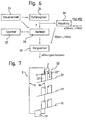
- FIG. 7 is the concatenation according to FIG. 3 shown as a safety chain for the door contacts of a lift system.
- On three floors 31 of a building elevator doors 32 are provided, which are formed in this example as shaft doors 32.
- Each landing door 32 has a first door 32 'and a second door 32 "movable relative to each other for opening and closing the door FIG. 4 represented by the arrows P.
- the first door 32 ' has the interrogation unit 2 and the second door 32 "includes the answering unit 3.
- the interrogation unit 2 and the answering unit 3 are arranged on the respective door 32', 32" so as to be so close when the landing door 32 is closed
- the interrogation units 2 and the response units 3 are preferably located on those parts of the respective door wings that overlap when the door is closed.
- the interrogation units 2 and the answering units 3 are preferably arranged on the corresponding door wings 32 ', 32 "such that they do not interact within the meaning of the invention until the door wings 32', 32" are already mechanically or electromechanically locked.
- the interrogation units 2 of each landing door 32 are connected in series via a bus line 13 and to a control unit 12.
- the query of the interrogation units 2, the answer of the answering units 3 as well as the data transmission to the control unit 12 functions exactly as in FIG. 3 is shown.
- this safety chain S operating in the manner according to the invention, the door contacts of the shaft doors can be safely monitored and uniquely identified. Wrong trips are avoided.
- the control unit 12 continuously monitors the state of the door contacts and is connected to a central elevator control, not shown, in a conventional manner.
- the monitoring device according to the invention can be used at all points of a lift to be secured, and the switching devices can replace all safety switches of a lift.
- the active and / or the passive unit can also be provided with switching contacts or with semiconductor switches, for example, put the energy storage or the antenna out of operation. This could be applied, for example, to existing mechanical contacts.
Abstract
Description
Die Erfindung betrifft eine Überwachungseinrichtung für einen Aufzug, die mindestens eine berührungslos betätigbare Schalteinrichtung umfasst.The invention relates to a monitoring device for an elevator, which comprises at least one non-contact operable switching device.
Eine überuschungseinrichtung ist z.B. aus
Bei Aufzugsanlagen werden einzelne Aktionen, zum Beispiel eine Fahrt eine Aufzuges, im allgemeinen mit Hilfe von Schalteinrichtungen überwacht. Mehrere von solchen Schalteinrichtungen müssen einen bestimmten Zustand haben, um die beabsichtige Aktion sicher durchführen zu können. Insbesondere muss bei einer Aufzugsanlage sichergestellt sein, dass vor Beginn und während der Fahrt der Aufzugskabine alle Türen geschlossen und mechanisch verriegelt bleiben.In elevator systems, individual actions, for example a ride on a lift, are generally monitored by means of switching devices. Several of such switching devices must have a certain state in order to perform the intended action safely. In particular, in the case of an elevator installation it must be ensured that all doors remain closed and mechanically locked before the start of and during the journey of the elevator cage.
Aus der Schrift
Nachteilig bei dieser Lösung ist die Tatsache, dass der Schalter bzw. der Sensor auf jeden Magnet reagiert, unabhängig davon, ob dieser Magnet der richtige und der zu dem gewählten Schalter bzw. Sensor bestimmte Magnet ist. Es genügt die Annäherung eines entsprechenden Materials, um ein gültiges Signal auszulösen. Sobald sich der Schalter im Wirkungsbereich des Magneten befindet, löst er ein gültiges Signal aus. Eine Fehlfunktion (falsche Auslösung) des Schalters bzw. des Sensors kann mit vernünftigem Aufwand kaum ausgeschlossen werden. Eine irrtümliche Auslösung kann auch zum Beispiel durch Artefakten und/oder externe Störungen verursacht werden, was für den sicheren Betrieb der Aufzugsanlage gefährlich ist.A disadvantage of this solution is the fact that the switch or the sensor responds to each magnet, regardless of whether this magnet is the right and the particular of the selected switch or sensor magnet. It is sufficient to approximate a corresponding material to trigger a valid signal. As soon as the switch is within the working range of the magnet, it triggers a valid signal. A malfunction (incorrect triggering) of the switch or the sensor can hardly be excluded with reasonable effort. An erroneous trip can also be caused for example by artifacts and / or external interference, which is dangerous for the safe operation of the elevator system.
Der Erfindung liegt die Aufgabe zugrunde, eine Überwachungseinrichtung für einen Aufzug der eingangs genannten Art vorzuschlagen, welche die vorgenannten Nachteile nicht aufweist und eine sichere und störungsfreie Überwachung ermöglicht. Weiter ist die Überwachungseinrichtung gegenüber Artefakten und externe Manipulationen unempfindlich. Mittels der Überwachungseinrichtung sind die zu überwachenden Komponenten eindeutig identifizierbar.The invention has for its object to provide a monitoring device for an elevator of the type mentioned, which does not have the aforementioned disadvantages and allows safe and trouble-free monitoring. Furthermore, the monitoring device is insensitive to artifacts and external manipulations. By means of the monitoring device, the components to be monitored are uniquely identifiable.
Diese Aufgabe wird durch die Merkmale der Patentanspruche 1 und 9 gelöst.This object is solved by the features of
Ein Vorteil ist darin zu sehen, dass ein gültiges Signal nur mit einer beispielsweise weltweit einzigen passiven Einheit ausgelöst werden kann. Die aktive Einheit kann kein gültiges Signal generieren, ohne die richtige passive Einheit in Reichweite zu haben. Ein weiterer Vorteil besteht darin, dass die Überwachung mit kostengünstig herstellbaren Elementen gewährleistet ist.One advantage is the fact that a valid signal can only be triggered with an example worldwide only passive unit. The active unit can not generate a valid signal without having the right passive unit in range. Another advantage is that the monitoring is ensured with inexpensive producible elements.
Durch die in den abhängigen Patentansprüchen aufgeführte Massnahmen sind vorteilhafte Weiterbildungen und Verbesserungen der im Anspruch 1 angegebenen Überwachungseinrichtung möglich.The measures listed in the dependent claims advantageous developments and improvements of the claim 1 monitoring device are possible.
Ein weiterer Vorteil besteht darin, dass gleichzeitig mehrere Schalteinrichtungen bezüglich Funktionsfähigkeit und Zustand überwacht werden können. Die Verkettung mehrerer aktiver Einheiten erfolgt derart, dass die Antworten aller passiven Einheiten so verknüpft werden, dass eine gegenseitige Beeinflussung im Sinne einer Falschinterpretation ausgeschlossen werden kann.Another advantage is that several switching devices can be monitored for functionality and condition at the same time. The concatenation of several active units takes place in such a way that the answers of all passive units are linked in such a way that a mutual influence in the sense of a misinterpretation can be excluded.
Vorteilhaft ist weiter die Tatsache, dass ein Datenaustausch zwischen aktiver und passiver Einheit nur durch Annäherung der als Antenne arbeitenden Spulen stattfinden kann.Another advantage is the fact that a data exchange between active and passive unit can take place only by approaching the working as an antenna coils.
Weiter ist vorteilhaft, dass die passive Einheit keine eigene Energieversorgung oder Batterie braucht. Dies wird dadurch erreicht, dass sie einen Energiespeicher aufweist, in dem die durch die aktive Einheit übermittelte Energie gespeichert werden kann. Es wird somit Energie gespart. Da die Energie zur Generierung der Antwort übertragen werden muss, ist keine Spontanaktivität möglich.It is also advantageous that the passive unit does not need its own power supply or battery. This is achieved by having an energy store in which the energy transmitted by the active unit can be stored. This saves energy. Since the energy must be transmitted to generate the response, no spontaneous activity is possible.
Verschiedene Ausführungsbeispiele der Erfindung sind in den schematischen Zeichnungen dargestellt und in der nachfolgenden Beschreibung näher erläutert. Es zeigen:
-
Fig. 1 eine Schalteinrichtung der Sicherheitskette im Ruhezustand, d.h. im unwirksamen Zustand, -
Fig. 2 die Schalteinrichtung ausFig. 1 im Betriebszustand, d.h. im wirksamen Zustand, -
Fig. 3 eine Verkettung mehrerer Schalteinrichtungen, -
Fig. 4 eine passive Einheit gemäss einer Ausführungsform der Erfindung, -
Fig. 5 eine aktive Einheit gemäss einer Ausführungsform der Erfindung, -
Fig. 6 eine zentrale Kontrolleinheit gemäss einer Ausführungsform der Erfindung, -
Fig. 7 eine Sicherheitskette für die Türkontakte einer Aufzugsanlage.
-
Fig. 1 a switching device of the safety chain at rest, ie in the inoperative state, -
Fig. 2 the switching device offFig. 1 in the operating state, ie in the active state, -
Fig. 3 a chain of several switching devices, -
Fig. 4 a passive unit according to an embodiment of the invention, -
Fig. 5 an active unit according to an embodiment of the invention, -
Fig. 6 a central control unit according to an embodiment of the invention, -
Fig. 7 a safety chain for the door contacts of a lift installation.
In
In
In einer Ausführungsform kann die Abfrageeinheit 2 einen Generator 6, einen ersten Modulator 7 und einen ersten Demodulator 8 aufweisen. Der Generator 6 kann beispielsweise ein HF-Generator, ein RF-Generator und so weiter sein. Die Antworteinheit 3 kann seinerseits einen zweiten Modulator 9 und einen zweiten Demodulator 10 aufweisen. Die Antworteinheit 3 kann weiter einen Energiespeicher 11 aufweisen, der zum Beispiel als Kondensator mit einer Kapazität ausgebildet sein kann. Die Antworteinheit 3 besitzt also vorzugsweise keine eigene Energieversorgung oder Batterie.In one embodiment, the
Das wesentliche Funktionsprinzip des Systems Abfrageeinheit 2-Antworteinheit 3, wird in einer bevorzugten Ausführungsform, im folgenden näher beschrieben:The essential operating principle of the system interrogation unit 2-
Die Abfrageeinheit 2 ist so ausgebildet, dass sie in der Lage ist, Informationen zur Antworteinheit 3 zu übertragen und/oder Informationen von der Antworteinheit 3 zu erhalten. Die erste Spule 4 und die zweite Spule 5 sind in diesem Beispiel als Antenne ausgebildet. Die Abfrageeinheit 2 übermittelt der Antworteinheit 3 die Energie über ein elektromagnetisches Feld. Es wird von elektromagnetischer Kopplung gesprochen, da die Energieübertragung ähnlich wie in einem Transformator funktioniert, wo die Energie von der Primärwicklung durch enge Kopplung auf die Sekundärwicklung übertragen wird. Die über das elektromagnetische Feld eingekoppelte Energie speichert die Antworteinheit 3 temporär im Energiespeicher 11. Sobald die Antworteinheit 3 genügend Energie erhalten hat, wird sie funktionstüchtig und antwortet in sehr spezifischer Art und Weise auf das von der Abfrageeinheit 2 generierte Muster M.The
Das Muster M und/oder die Antwort M' können beispielsweise Zahlen sein, die durch ein Bitmuster/Bitfolge dargestellt sind. Das die Antworteinheit 3 erregende Muster M braucht nicht sehr komplex zu sein, da es in erster Linie der Übertragung von Energie und der Auslösung einer Antwort M' dient. In einer Ausführungsform kann das Muster M etwa ein HF-Träger sein und als phasenmoduliertes HF-Signal generiert werden. Das Muster M wird von der Antworteinheit 3 lediglich zur Energiegewinnung und Synchronisation einer Antwort verwendet. Mit anderen Worten kann das Muster M als Anweisung an die Antworteinheit 3 verstanden werden, eine entsprechende Antwort M' zu generieren.The pattern M and / or the answer M 'may be, for example, numbers represented by a bit pattern / bit sequence. The pattern M exciting the
Auf diese Weise ist eine kausale Verknüpfung von Antwort und Anfrage sichergestellt.In this way a causal link between answer and inquiry is ensured.
Das Muster M braucht nicht konstant zu sein und kann durch die Abfrageeinheit 2 oder von Aussen vorgegeben werden.The pattern M need not be constant and may be specified by the
Es könnte aber auch ein Datenaustausch nach klassischen Modulationsverfahren (Amplitudenmodulation AM, Frequenzmodulation FM, usw.) zwischen der Abfrageeinheit 2 und der Antworteinheit 3 stattfinden.However, it would also be possible to exchange data according to classical modulation methods (amplitude modulation AM, frequency modulation FM, etc.) between the
Die Antworteinheit 3 verändert das Muster M derart, dass sichergestellt ist, dass diese Veränderung durch die entsprechende Antworteinheit 3 selbst und nicht durch ein anderes Element erfolgt. Dies kann beispielsweise dadurch erfolgen, dass die Antworteinheit 3 auf eine Anfrage mit der Übertragung einer eineindeutigen Zahl antwortet. Damit ist die Antworteinheit 3 eindeutig identifiziert.The
Die Kommunikation mit der zentralen Kontrolleinheit 12 und die Datenübertagung zu derselben erfolgt über einen Bus 13.The communication with the
Die charakteristische Funktion fi(x) der Antworteinheit 3 ist beispielsweise in einer Tabelle abgespeichert. Dies bedeutet, dass das Ermitteln des Funktionswertes auf das Auslesen eines durch das Funktionsargument adressierten Speichers zurückgeführt wird. Der Aufbau der Tabelle kann dabei in einem einmaligen Initialisierungszyklus erfolgen. Die Tabelleninhalte werden so gewählt, dass diese über alle Antworteinheiten verschieden sind. Dazu kann etwa die lineare Funktion fi(x) = ui+vi*x verwendet werden, wobei sichergestellt wird, dass die Bildbereiche je disjunkt sind. Sollen auch Teilmengen von Antworteinheiten 3 in einem Kreis identifiziert werden, so sind die Anforderungen entsprechend strenger zu wählen. Im allgemeinen Falls müssen alle additiven Teilmengen disjunkt sein.The characteristic function fi (x) of the
Eine bevorzugte Ausführungsvariante ergibt sich aus einer Anordnung wie sie in den folgenden
In
Die Konfiguration des Adresse-/Dataspeichers, so dass die Inhalte an den Adressen x den Werten f(x) entsprechen, kann auch über analoge Mechanismen mit entsprechenden Kommandos oder aber separat, zum Beispiel mittels Laser und bleibender Veränderung der Halbleiterstruktur, erfolgen.The configuration of the address / data memory so that the contents at the addresses x correspond to the values f (x) can also be effected via analogous mechanisms with corresponding commands or else separately, for example by means of a laser and a permanent change in the semiconductor structure.
Die Verknüpfung der Antworten M' mehrerer Antworteinheiten erfolgt durch serielle Addition der Einzelresultate entlang einem Bus 13. Mittels diesem lassen sich, unter Verwendung entsprechender Kommandos, auch die Abfragen der Antworteinheiten 3 auslösen.The linking of the answers M 'of several response units is carried out by serial addition of the individual results along a
In
Ein Abfragekommando r(x), welches entlang dem Bus propagiert wird, löst in jeder Abfrageeinheit die Generierung eines Musters M(R,x) aus. Anschliessend wird der weitere Zwischen-Dataspeicher 22 auf den Wert 0 gesetzt. Alle Antworteinheiten 3, welche sich in genügender Nähe der weiteren Antenne 19 befinden, antworten daraufhin mit der Antwort M'(A,f(x)). Diese wird demoduliert und im weiteren Zwischen-Dataspeicher 22 als Resultat abgelegt. Erfolgt daraufhin eine Anweisung a(w) mit Argument w durch den Bus 13, so wird im seriellen Addierer 23 die Summe w+f(x) generiert und über die Busankopplung 24 als a(w+f(x)) weitergereicht.A query command r (x), which is propagated along the bus, triggers the generation of a pattern M (R, x) in each interrogation unit. Subsequently, the further
Zur Auswertung des Ergebnisses wird das durch die Summation über alle Tags ermittelte Resultat mit dem durch die Abfrageeinheit ermittelten verglichen, und bei Übereinstimmung der Sicherheitskreis als geschlossen bewertet.To evaluate the result, the result determined by the summation over all tags is compared with that determined by the interrogation unit, and if the safety circuit matches, it is evaluated as closed.
In
Zur Bestimmung des Zustandes des Sicherheitskreises wird vom Zufallsgenerator 26 ein Zufallsargument x generiert und an die Abfrageeinheiten 2 als Kommando r(x) ausgegeben. Das Zufallargument x wird dann einer Adresse der Adresse-/Dataspeicher 14 der Antworteinheit 3 entsprechen. Gleichzeitig wird, mittels der im Speicher 27 abgelegten Informationen betreffend die Funktionen fi, der "Sollwert" f^0(x)+...+f^N(x) berechnet. Dabei werden all jene Antworteinheiten T0 ... TN berücksichtigt, welche zur Erreichung eines bestimmten Sicherheitszustandes notwendig sind. Nach einer wohlbestimmten Zeitdauer erfolgt die Abfrage der Resultate mittels der Anweisung a(0). Das so ermittelte Resultat f0(x)+ ...+fN(x) wird im Vergleicher 29 mit dem Sollwert verglichen und, entsprechend dem Resultat, entweder die Direktive "Kreis geschlossen" oder "Kreis offen" ausgegeben. Eine Bewertung des Sicherheitszustandes kann zyklisch oder auf Anfrage hin erfolgen.To determine the state of the safety circuit, a random argument x is generated by the
Es können auch andere Funktionen f(x) verwendet werden. Idealerweise wird f so gewählt, dass zur Prüfung des Resultates ein einfaches Kriterium anwendbar ist. Im Idealfall ist die Bestimmung von f(x) sehr schwierig, die Prüfung von der Gleichheitsrelation w = f(x) hingegen sehr einfach. Derartige Funktionen sind unter dem Begriff "One Way Function" oder "Trap Door Function" im Bereich der Kryptographie hinreichend bekannt. Die Funktion braucht nicht zwingend skalare Resultate zu liefern.Other functions f (x) can also be used. Ideally, f is chosen so that a simple criterion can be used to test the result. Ideally, the determination of f (x) is very difficult, while the examination of the equality relation w = f (x) is very simple. Such functions are well known by the term "one-way function" or "trap door function" in the field of cryptography. The function does not necessarily have to deliver scalar results.
Zur Kommunikation können verschiedenste bekannte Bussystem verwendet werden. Da die Sicherheit auf einer höheren Hierarchie-Ebene gewährleistet wird, sind die Anforderungen an das Bussystem selbst sehr gering.For communication a variety of known bus system can be used. Since the security is ensured at a higher hierarchical level, the requirements for the bus system itself are very low.
Die Verkettung der Abfragestationen kann auch durch andere Funktionen als die Addition bewerkstelligt werden.The concatenation of the interrogation stations can also be accomplished by other functions than the addition.
Die Sicherheitsanforderungen an die Komponenten sind gering. Die Sicherheit ergibt sich in erster Linie durch die Handhabung von Information. Es braucht lediglich sichergestellt zu werden, dass der Vergleicher sicher arbeitet und dessen Eingangssignale aus unabhängigen Quellen (Berechung/Bus) stammen.The safety requirements for the components are low. Security comes first and foremost through the handling of information. It only needs to be ensured that the comparator operates safely and whose input signals originate from independent sources (calculation / bus).
In Bezug auf die gezeigte Sicherheitskette S gemäss
In
Das gleiche Prinzip kann auch für die Kabinentüre des Aufzuges angewendet werden.The same principle can also be applied to the car door of the elevator.
Die Überwachungseinrichtung gemäss der Erfindung kann an allen zu sichernden stellen eines Aufzuges verwendet werden, und die Schalteinrichtungen können alle Sicherheitsschalter eines Aufzuges ersetzen.The monitoring device according to the invention can be used at all points of a lift to be secured, and the switching devices can replace all safety switches of a lift.
Die aktive und/oder die passive Einheit können auch mit Schaltkontakten oder mit Halbleiterschaltern versehen werden, die beispielsweise den Energiespeicher oder die Antenne ausser Betrieb setzen. Dies könnte zum Beispiel bei bestehenden mechanischen Kontakten angewendet werden.The active and / or the passive unit can also be provided with switching contacts or with semiconductor switches, for example, put the energy storage or the antenna out of operation. This could be applied, for example, to existing mechanical contacts.
- 11
- Schalteinrichtungswitching device
- 22
- Abfrageeinheitinterrogation unit
- 33
- Antworteinheitresponse unit
- 44
- Erste SpuleFirst coil
- 55
- Zweite SpuleSecond coil
- 66
- Generatorgenerator
- 77
- Erster ModulatorFirst modulator
- 88th
- Erster DemodulatorFirst demodulator
- 99
- Zweiter ModulatorSecond modulator
- 1010
- Zweiter DemodulatorSecond demodulator
- 1111
- Energiespeicherenergy storage
- 1212
- Zentrale KontrolleinheitCentral control unit
- 1313
- Serieller Kanal / BusSerial channel / bus
- 1414
- Adresse-/DataspeicherAddress / data storage
- 1515
- Zwischen-DataspeicherIntermediate data store
- 1616
- Lokale KontrolleinheitLocal control unit
- 1717
- Modulations-/DemodulationseinheitModulation / demodulation
- 1818
- Antenneantenna
- 1919
- Weitere AntenneAnother antenna
- 2020
- Weitere Modulations-/DemodulationseinheitFurther modulation / demodulation unit
- 2121
- Weitere lokale KontrolleinheitAnother local control unit
- 2222
- Weiterer Zwischen-DataspeicherAnother intermediate data store
- 2323
- Addiereradder
- 2424
- Busankopplungbus connection
- 2525
- Steuereinheitcontrol unit
- 2626
- Zufallgeneratorrandom generator
- 2727
- SpeicherStorage
- 2828
- Rechnercomputer
- 2929
- Vergleichercomparator
- 3030
- Kopplungcoupling
- 3131
- Stockwerk eines GebäudesFloor of a building
- 3232
- Aufzugstürelevator door
- 32'32 '
- Erster TürflügelFirst door
- 32"32 "
- Zweiter TürflügelSecond door leaf
- MM
- Mustertemplate
- M'M '
- Antwortanswer
- PP
- Schliessrichtung der SchachttürClosing direction of the shaft door
- SS
- Sicherheitskettesafety chain
Claims (8)
- Monitoring device for a lift, which comprises at least one contactlessly actuable switching device (1), which comprises an active unit (2) and a passive unit (3), wherein the active unit (2) and the passive unit (3) are so constructed that the passive unit (3) is excited exclusively by a pattern (M) generated by the active unit (2), wherein the passive unit (3) is excited by the pattern (M) from the active unit (2) from a defined spacing between the active and passive units (2, 3) and generates an answer (M'), wherein the answer (M') is transmissable as identification signal to a central checking unit (12) by way of a bus (13), characterised in that several switching devices (1) are provided which are serially connected together into a safety chain (S) by way of the bus (13) to the central checking unit (12) and that the pattern (M) and the answer (M') are numbers which can be represented by a bit pattern / bit sequence, wherein each passive unit (3) has a characteristic function fi(x) and the pattern (M) with the respective characteristic function fi(x) is processed so that the passive unit (3) is uniquely identifiable and wherein the respective answers (M'), which have the form of electromagnetic data, are converted into data-word data and interlinked along the bus (13) by means of a function and the result is reported back to the central checking unit (12).
- Monitoring device according to one claim 1, characterised in that the active unit (2) comprises a first coil (4) and the passive unit (3) comprises a second coil (5).
- Monitoring device according to one of the preceding claims, characterised in that the passive unit (3) comprises an energy store (11) which stores energy.
- Monitoring device according to any one of the preceding claims, characterised in that the lift comprises at least one lift door (32), which comprises a first door panel (32') and a second door panel (32"), wherein the active unit (2) is arranged at the first door panel (32') and the passive unit (3) is arranged at the second door panel (32").
- Monitoring device according to claim 4, characterised in that the lift door (32) is a shaft door or a cage door.
- Monitoring device according to any one of the preceding claims, characterised in that the active unit (2) is constructed as a transceiver and the passive unit (3) as a transponder.
- Method of monitoring a lift with at least one contactlessly actuable switching device (1), which comprises an active unit (2) and a passive unit (3), wherein the passive unit (3) is excited exclusively by a pattern (M) generated by the active unit (2), wherein the passive unit (3) is excited by the pattern (M) from the active unit (2) from a defined spacing between the active and passive units (2, 3) and generates an answer (M'), wherein the answer (M') is transmissable as identification signal to a central checking unit (12) by way of a bus (13), characterised in that several switching devices (1) are serially connected together into a safety chain (S) by way of the bus (13) to the central checking unit (12) and that as pattern (M) and the answer (M') numbers are used which can be represented by a bit pattern / bit sequence, wherein each passive unit (3) uses a characteristic function fi(x) and the pattern (M) with the respective characteristic function fi(x) is processed so that the passive unit (3) is uniquely identifiable and wherein the respective answers (M'), which have the form of electromagnetic data, are converted into data-word data and interlinked along the bus (13) by means of a function and the result is reported back to the central checking unit (12).
- Method according to claim 7, characterised in that no answer (M') is generated by the passive unit (3) if the defined spacing is exceeded.
Priority Applications (2)
| Application Number | Priority Date | Filing Date | Title |
|---|---|---|---|
| EP01957667A EP1307395B2 (en) | 2000-08-07 | 2001-08-02 | Monitoring device for an elevator |
| CY20071100157T CY1105988T1 (en) | 2000-08-07 | 2007-02-05 | SURVEILLANCE EQUIPMENT THROUGH AN ELEVATOR |
Applications Claiming Priority (4)
| Application Number | Priority Date | Filing Date | Title |
|---|---|---|---|
| EP00810706 | 2000-08-07 | ||
| EP00810706 | 2000-08-07 | ||
| PCT/CH2001/000474 WO2002012109A1 (en) | 2000-08-07 | 2001-08-02 | Monitoring device for an elevator |
| EP01957667A EP1307395B2 (en) | 2000-08-07 | 2001-08-02 | Monitoring device for an elevator |
Publications (3)
| Publication Number | Publication Date |
|---|---|
| EP1307395A1 EP1307395A1 (en) | 2003-05-07 |
| EP1307395B1 EP1307395B1 (en) | 2006-11-08 |
| EP1307395B2 true EP1307395B2 (en) | 2009-11-18 |
Family
ID=8174850
Family Applications (1)
| Application Number | Title | Priority Date | Filing Date |
|---|---|---|---|
| EP01957667A Expired - Lifetime EP1307395B2 (en) | 2000-08-07 | 2001-08-02 | Monitoring device for an elevator |
Country Status (14)
| Country | Link |
|---|---|
| US (1) | US6732839B2 (en) |
| EP (1) | EP1307395B2 (en) |
| JP (1) | JP2004505868A (en) |
| CN (1) | CN1232436C (en) |
| AT (1) | ATE344778T1 (en) |
| AU (2) | AU2001279531B2 (en) |
| CA (1) | CA2416902C (en) |
| CY (1) | CY1105988T1 (en) |
| DE (1) | DE50111416D1 (en) |
| DK (1) | DK1307395T3 (en) |
| ES (1) | ES2276809T5 (en) |
| IL (1) | IL153936A0 (en) |
| PT (1) | PT1307395E (en) |
| WO (1) | WO2002012109A1 (en) |
Families Citing this family (30)
| Publication number | Priority date | Publication date | Assignee | Title |
|---|---|---|---|---|
| ATE328841T1 (en) * | 2000-06-13 | 2006-06-15 | Cedes Ag | SAFETY DEVICE FOR ELEVATOR DOORS |
| US7191165B2 (en) * | 2001-06-04 | 2007-03-13 | Synopsys, Inc. | Transaction based design verification with hierarchical verification components |
| CA2478078C (en) | 2002-03-27 | 2011-05-17 | Inventio Ag | Shaft monitoring system for an elevator |
| JP4527362B2 (en) * | 2002-05-03 | 2010-08-18 | インベンテイオ・アクテイエンゲゼルシヤフト | Elevator shaft door monitoring method |
| FR2841084B1 (en) * | 2002-06-13 | 2004-12-17 | Systemig Sa | STATE REMOTE DEVICE AND APPLICATIONS |
| FR2841075B1 (en) * | 2002-06-13 | 2004-12-24 | Systemig Sa | MONITORING AND / OR MONITORING DEVICE USING AT LEAST ONE TRANSMISSION CONTROLLER |
| CN100519390C (en) | 2002-08-01 | 2009-07-29 | 奥蒂斯电梯公司 | Hoister using radio frequency identifying device (RFID) and hoister calling system |
| EP1418149B1 (en) * | 2002-11-08 | 2011-07-06 | Daniel Schürmann | Elevator door safety device |
| ATE350327T1 (en) * | 2003-04-30 | 2007-01-15 | Thyssenkrupp Elevator Ag | ELEVATOR SYSTEM AND METHOD FOR CONTROLLING AN ELEVATOR SYSTEM |
| CN1878714A (en) * | 2003-10-31 | 2006-12-13 | 奥蒂斯电梯公司 | RF ID and low resolution CCD sensor based positioning system |
| WO2006009536A2 (en) * | 2004-06-21 | 2006-01-26 | Otis Elevator Company | Elevator door coupler |
| EP1765713A4 (en) * | 2004-06-22 | 2010-03-03 | Otis Elevator Co | Elevator door position detection |
| US7823699B2 (en) * | 2004-07-06 | 2010-11-02 | Otis Elevator Company | Electromagnetically operated elevator door lock |
| WO2006025103A1 (en) * | 2004-08-31 | 2006-03-09 | Mitsubishi Denki Kabushiki Kaisha | Controller of one-shaft multi-car system elevator |
| WO2006024893A1 (en) * | 2004-09-03 | 2006-03-09 | Otis Elevator Company | Device for the detection of foreign objects, and particularly fingers, between the doors and the contiguous walls of an elevator car with glass doors, and elevator equipped therewith |
| EP1799604A4 (en) * | 2004-09-23 | 2010-03-10 | Otis Elevator Co | Elevator door lock |
| WO2006036146A1 (en) * | 2004-09-27 | 2006-04-06 | Otis Elevator Company | Elevator door lock sensor device |
| KR100968288B1 (en) * | 2005-04-01 | 2010-07-07 | 미쓰비시덴키 가부시키가이샤 | Electric-power supply system for elevator |
| DE102006013578B4 (en) * | 2006-03-22 | 2008-03-27 | Phoenix Contact Gmbh & Co. Kg | Method and control and data transmission system for checking the installation location of a secure communication subscriber |
| ATE549479T1 (en) * | 2006-09-12 | 2012-03-15 | Otis Elevator Co | DOOR ASSEMBLY INCLUDING A SENSOR FOR CONTROLLING AUTOMATED DOOR MOVEMENT |
| US7958970B2 (en) * | 2009-09-02 | 2011-06-14 | Empire Technology Development Llc | Acceleration sensor calibrated hoist positioning |
| EP2616376B1 (en) | 2010-09-13 | 2020-11-18 | Otis Elevator Company | Elevator safety system and method |
| WO2013020934A1 (en) * | 2011-08-11 | 2013-02-14 | Inventio Ag | Function-monitoring of a safety element |
| EP2567926B1 (en) * | 2011-09-06 | 2013-10-09 | Cedes AG | Circuit device, safety device and lift device |
| FI123145B (en) * | 2012-01-23 | 2012-11-30 | Kone Corp | Method and arrangement for monitoring the functioning of the transport system |
| TWI622548B (en) | 2012-12-13 | 2018-05-01 | 伊文修股份有限公司 | Monitoring device for a transport installation for persons, trasnport installation for persons, and method of monitoring a transport installation for persons |
| BR112015029394B1 (en) * | 2013-05-28 | 2022-11-29 | Inventio Ag | SWITCH DEVICE FOR AN ELEVATOR DOOR FOR PROVIDING A DOOR CONTACT SIGNAL, ELEVATOR DOOR AND PROCESS FOR PROVIDING A DOOR CONTACT SIGNAL |
| EP3374832B1 (en) | 2015-11-09 | 2019-10-16 | Otis Elevator Company | Self-diagnostic electrical circuit |
| US11919746B2 (en) | 2016-05-04 | 2024-03-05 | Inventio Ag | Passenger transport system having central control unit and multiple field devices having an optimized failure detection method |
| US20200207574A1 (en) * | 2017-09-13 | 2020-07-02 | Inventio Ag | Status checking of field devices of a building-associated installation for transporting people |
Citations (4)
| Publication number | Priority date | Publication date | Assignee | Title |
|---|---|---|---|---|
| US3859624A (en) † | 1972-09-05 | 1975-01-07 | Thomas A Kriofsky | Inductively coupled transmitter-responder arrangement |
| DE4032033A1 (en) † | 1990-10-09 | 1992-04-16 | Siemens Ag | Electric control and monitoring for underground plant - triggering safety-relevant signals for transmission over independent paths and processing by redundant systems |
| US5682024A (en) † | 1995-07-31 | 1997-10-28 | Otis Elevator Company | Elevator position determination |
| WO1998045764A1 (en) † | 1997-04-07 | 1998-10-15 | Euchner Gmbh & Co. | Safety switch |
Family Cites Families (20)
| Publication number | Priority date | Publication date | Assignee | Title |
|---|---|---|---|---|
| US3054475A (en) * | 1956-12-18 | 1962-09-18 | Schweiz Wagons Aufzuegefab | Safety device for an elevator door |
| JPS6232496U (en) * | 1985-08-06 | 1987-02-26 | ||
| NL8701565A (en) * | 1987-07-03 | 1989-02-01 | Nedap Nv | IDENTIFICATION SYSTEM WITH TWO OPERATING MODES. |
| US5107964A (en) * | 1990-05-07 | 1992-04-28 | Otis Elevator Company | Separate elevator door chain |
| DE4112626A1 (en) * | 1991-04-18 | 1992-10-22 | Fraunhofer Ges Forschung | MONITORING DEVICE FOR A CONTROL DEVICE |
| US5300875A (en) * | 1992-06-08 | 1994-04-05 | Micron Technology, Inc. | Passive (non-contact) recharging of secondary battery cell(s) powering RFID transponder tags |
| JPH0761726A (en) * | 1993-08-23 | 1995-03-07 | Shimizu Corp | Call display device for temporary elevator |
| US5708416A (en) * | 1995-04-28 | 1998-01-13 | Otis Elevator Company | Wireless detection or control arrangement for escalator or moving walk |
| JPH1045344A (en) * | 1996-08-05 | 1998-02-17 | Toshiba Corp | Group control device of elevator |
| JP3465869B2 (en) * | 1997-04-11 | 2003-11-10 | ニッタン株式会社 | Anomaly detection device and anomaly monitoring system |
| DE69827908T2 (en) * | 1997-04-24 | 2005-12-22 | Koninklijke Philips Electronics N.V. | TRANSPONDER FOR TOUCHLESS INDUCTIVE COMMUNICATION |
| DE19737464A1 (en) * | 1997-08-28 | 1999-03-04 | Datasec Electronic Gmbh | Contactless switch unit for operating opening systems with locking mechanisms e.g. doors |
| US5945920A (en) * | 1997-12-10 | 1999-08-31 | Atmel Corporation | Minimum voltage radio frequency indentification |
| FI109468B (en) * | 1998-11-05 | 2002-08-15 | Kone Corp | Pinion Elevator |
| US6173814B1 (en) * | 1999-03-04 | 2001-01-16 | Otis Elevator Company | Electronic safety system for elevators having a dual redundant safety bus |
| JP3864647B2 (en) * | 1999-11-26 | 2007-01-10 | 株式会社日立製作所 | Elevator system |
| JP3857508B2 (en) * | 2000-08-29 | 2006-12-13 | 株式会社日立製作所 | Elevator equipment |
| DE10108772A1 (en) * | 2001-02-23 | 2002-11-21 | Otis Elevator Co | Elevator safety device |
| US6601679B2 (en) * | 2001-09-05 | 2003-08-05 | Otis Elevator Company | Two-part wireless communications system for elevator hallway fixtures |
| US20030089558A1 (en) * | 2001-11-09 | 2003-05-15 | Otis Elevator Company | Power line carrier used in elevator system |
-
2001
- 2001-08-02 AT AT01957667T patent/ATE344778T1/en not_active IP Right Cessation
- 2001-08-02 IL IL15393601A patent/IL153936A0/en not_active IP Right Cessation
- 2001-08-02 AU AU2001279531A patent/AU2001279531B2/en not_active Ceased
- 2001-08-02 CN CNB01813842XA patent/CN1232436C/en not_active Expired - Lifetime
- 2001-08-02 WO PCT/CH2001/000474 patent/WO2002012109A1/en active IP Right Grant
- 2001-08-02 PT PT01957667T patent/PT1307395E/en unknown
- 2001-08-02 CA CA2416902A patent/CA2416902C/en not_active Expired - Lifetime
- 2001-08-02 EP EP01957667A patent/EP1307395B2/en not_active Expired - Lifetime
- 2001-08-02 DK DK01957667T patent/DK1307395T3/en active
- 2001-08-02 JP JP2002517416A patent/JP2004505868A/en not_active Ceased
- 2001-08-02 ES ES01957667T patent/ES2276809T5/en not_active Expired - Lifetime
- 2001-08-02 DE DE50111416T patent/DE50111416D1/en not_active Expired - Lifetime
- 2001-08-02 AU AU7953101A patent/AU7953101A/en active Pending
-
2003
- 2003-01-29 US US10/353,648 patent/US6732839B2/en not_active Expired - Lifetime
-
2007
- 2007-02-05 CY CY20071100157T patent/CY1105988T1/en unknown
Patent Citations (4)
| Publication number | Priority date | Publication date | Assignee | Title |
|---|---|---|---|---|
| US3859624A (en) † | 1972-09-05 | 1975-01-07 | Thomas A Kriofsky | Inductively coupled transmitter-responder arrangement |
| DE4032033A1 (en) † | 1990-10-09 | 1992-04-16 | Siemens Ag | Electric control and monitoring for underground plant - triggering safety-relevant signals for transmission over independent paths and processing by redundant systems |
| US5682024A (en) † | 1995-07-31 | 1997-10-28 | Otis Elevator Company | Elevator position determination |
| WO1998045764A1 (en) † | 1997-04-07 | 1998-10-15 | Euchner Gmbh & Co. | Safety switch |
Also Published As
| Publication number | Publication date |
|---|---|
| CA2416902A1 (en) | 2003-01-22 |
| EP1307395A1 (en) | 2003-05-07 |
| DE50111416D1 (en) | 2006-12-21 |
| EP1307395B1 (en) | 2006-11-08 |
| US6732839B2 (en) | 2004-05-11 |
| WO2002012109A1 (en) | 2002-02-14 |
| AU7953101A (en) | 2002-02-18 |
| IL153936A0 (en) | 2003-07-31 |
| PT1307395E (en) | 2007-02-28 |
| US20030111300A1 (en) | 2003-06-19 |
| CA2416902C (en) | 2010-03-23 |
| AU2001279531B2 (en) | 2006-09-07 |
| ATE344778T1 (en) | 2006-11-15 |
| CN1232436C (en) | 2005-12-21 |
| DK1307395T3 (en) | 2007-02-12 |
| CY1105988T1 (en) | 2011-04-06 |
| CN1446175A (en) | 2003-10-01 |
| ES2276809T5 (en) | 2010-04-19 |
| ES2276809T3 (en) | 2007-07-01 |
| JP2004505868A (en) | 2004-02-26 |
Similar Documents
| Publication | Publication Date | Title |
|---|---|---|
| EP1307395B2 (en) | Monitoring device for an elevator | |
| DE69906526T2 (en) | ANTI-COLLISION DEVICE AND SYSTEM FOR LABELS | |
| EP2401221B1 (en) | Lift with a monitoring system | |
| DE69831514T2 (en) | identification system | |
| DE3305685C2 (en) | Identification mark for a communication device as well as communication device and communication system | |
| DE112015003535B4 (en) | Onboard device, train and signaling security system | |
| EP0755026A2 (en) | Method for automatically identifying an unknown number of transponders by a reader and identification system for performing the method | |
| DE3715976A1 (en) | METHOD AND CIRCUIT FOR THE AUTOMATIC IDENTIFICATION OF LIVING BEINGS AND ITEMS | |
| DE60012378T2 (en) | Method and device for address assignment to components in a control system | |
| DE4026439A1 (en) | ELECTRONICALLY CONTROLLED LOCKING SYSTEM | |
| EP1526474B1 (en) | Method for selecting one or more transponders | |
| EP2012144B1 (en) | Light grid and method for operating a light grid | |
| EP1586917A2 (en) | Method for choosing one or more transponders | |
| EP0267528B1 (en) | Digital data transmission system with adressable repeaters having fault localization devices | |
| DE60308529T2 (en) | ANTI-COLLISION PROCESS WITH TIMELETS PROCESSING INFORMATION WHICH MARKS THE TIMER | |
| DE102004020956A1 (en) | Communication methods in RFID or remote sensor systems | |
| DE69829819T2 (en) | TRANSPONDER COMMUNICATIONS DEVICE | |
| DE2626619A1 (en) | MAGNETIC CARD READING SYSTEM FOR INDIRECT OPERATION THAT CAN WORK LIKE IN DIRECT OPERATION | |
| DE19901984A1 (en) | System for the automatic identification of at least one transponder in an electromagnetic field of a base station | |
| EP2955701A2 (en) | Radio controlled electromechanical locking system and method for operating a radio controlled electromechanical locking system | |
| EP3376430A1 (en) | Method of assigning addresses in modules of a system consisting of at least two rfid antennae and gate antenna arrangement comprised of at least two rfid antennae | |
| EP1488368B1 (en) | Method for coding a sequence of data bytes, especially for transferring via an air interface | |
| EP3910529A1 (en) | Method for local detection and tracking of rfid transponders using a reader device | |
| EP1106450A2 (en) | Activation and/or deactivation device for a security device | |
| DE10060800A1 (en) | Transponder interrogation system has transmitters and/or receivers operated at intervals for reducing overall electromagnetic radiation level |
Legal Events
| Date | Code | Title | Description |
|---|---|---|---|
| PUAI | Public reference made under article 153(3) epc to a published international application that has entered the european phase |
Free format text: ORIGINAL CODE: 0009012 |
|
| 17P | Request for examination filed |
Effective date: 20030205 |
|
| AK | Designated contracting states |
Designated state(s): AT BE CH CY DE DK ES FI FR GB GR IE IT LI LU MC NL PT SE TR |
|
| AX | Request for extension of the european patent |
Extension state: AL LT LV MK RO SI |
|
| 17Q | First examination report despatched |
Effective date: 20030807 |
|
| GRAP | Despatch of communication of intention to grant a patent |
Free format text: ORIGINAL CODE: EPIDOSNIGR1 |
|
| GRAS | Grant fee paid |
Free format text: ORIGINAL CODE: EPIDOSNIGR3 |
|
| GRAA | (expected) grant |
Free format text: ORIGINAL CODE: 0009210 |
|
| AK | Designated contracting states |
Kind code of ref document: B1 Designated state(s): AT BE CH CY DE DK ES FI FR GB GR IE IT LI LU MC NL PT SE TR |
|
| REG | Reference to a national code |
Ref country code: GB Ref legal event code: FG4D Free format text: NOT ENGLISH |
|
| REG | Reference to a national code |
Ref country code: CH Ref legal event code: EP |
|
| REG | Reference to a national code |
Ref country code: IE Ref legal event code: FG4D Free format text: LANGUAGE OF EP DOCUMENT: GERMAN |
|
| REF | Corresponds to: |
Ref document number: 50111416 Country of ref document: DE Date of ref document: 20061221 Kind code of ref document: P |
|
| REG | Reference to a national code |
Ref country code: DK Ref legal event code: T3 |
|
| GBT | Gb: translation of ep patent filed (gb section 77(6)(a)/1977) |
Effective date: 20070124 |
|
| REG | Reference to a national code |
Ref country code: GR Ref legal event code: EP Ref document number: 20070400300 Country of ref document: GR |
|
| REG | Reference to a national code |
Ref country code: SE Ref legal event code: TRGR |
|
| REG | Reference to a national code |
Ref country code: PT Ref legal event code: SC4A Free format text: AVAILABILITY OF NATIONAL TRANSLATION Effective date: 20070122 |
|
| ET | Fr: translation filed | ||
| REG | Reference to a national code |
Ref country code: ES Ref legal event code: FG2A Ref document number: 2276809 Country of ref document: ES Kind code of ref document: T3 |
|
| PLBI | Opposition filed |
Free format text: ORIGINAL CODE: 0009260 |
|
| PLAX | Notice of opposition and request to file observation + time limit sent |
Free format text: ORIGINAL CODE: EPIDOSNOBS2 |
|
| 26 | Opposition filed |
Opponent name: OTIS ELEVATOR COMPANY Effective date: 20070807 |
|
| NLR1 | Nl: opposition has been filed with the epo |
Opponent name: OTIS ELEVATOR COMPANY |
|
| PLBB | Reply of patent proprietor to notice(s) of opposition received |
Free format text: ORIGINAL CODE: EPIDOSNOBS3 |
|
| PUAH | Patent maintained in amended form |
Free format text: ORIGINAL CODE: 0009272 |
|
| STAA | Information on the status of an ep patent application or granted ep patent |
Free format text: STATUS: PATENT MAINTAINED AS AMENDED |
|
| PGFP | Annual fee paid to national office [announced via postgrant information from national office to epo] |
Ref country code: DK Payment date: 20090811 Year of fee payment: 9 Ref country code: IE Payment date: 20090821 Year of fee payment: 9 Ref country code: MC Payment date: 20090813 Year of fee payment: 9 |
|
| 27A | Patent maintained in amended form |
Effective date: 20091118 |
|
| AK | Designated contracting states |
Kind code of ref document: B2 Designated state(s): AT BE CH CY DE DK ES FI FR GB GR IE IT LI LU MC NL PT SE TR |
|
| PGFP | Annual fee paid to national office [announced via postgrant information from national office to epo] |
Ref country code: AT Payment date: 20090814 Year of fee payment: 9 Ref country code: LU Payment date: 20090820 Year of fee payment: 9 Ref country code: PT Payment date: 20090729 Year of fee payment: 9 Ref country code: SE Payment date: 20090813 Year of fee payment: 9 Ref country code: TR Payment date: 20090722 Year of fee payment: 9 |
|
| REG | Reference to a national code |
Ref country code: CH Ref legal event code: AEN Free format text: AUFRECHTERHALTUNG DES PATENTES IN GEAENDERTER FORM |
|
| PGFP | Annual fee paid to national office [announced via postgrant information from national office to epo] |
Ref country code: CY Payment date: 20090729 Year of fee payment: 9 |
|
| NLR2 | Nl: decision of opposition |
Effective date: 20091118 |
|
| NLR3 | Nl: receipt of modified translations in the netherlands language after an opposition procedure | ||
| REG | Reference to a national code |
Ref country code: ES Ref legal event code: DC2A Date of ref document: 20100217 Kind code of ref document: T5 |
|
| PGFP | Annual fee paid to national office [announced via postgrant information from national office to epo] |
Ref country code: GR Payment date: 20090825 Year of fee payment: 9 |
|
| PG25 | Lapsed in a contracting state [announced via postgrant information from national office to epo] |
Ref country code: DK Free format text: LAPSE BECAUSE OF FAILURE TO SUBMIT A TRANSLATION OF THE DESCRIPTION OR TO PAY THE FEE WITHIN THE PRESCRIBED TIME-LIMIT Effective date: 20100218 |
|
| PG25 | Lapsed in a contracting state [announced via postgrant information from national office to epo] |
Ref country code: GR Free format text: LAPSE BECAUSE OF FAILURE TO SUBMIT A TRANSLATION OF THE DESCRIPTION OR TO PAY THE FEE WITHIN THE PRESCRIBED TIME-LIMIT Effective date: 20100219 |
|
| REG | Reference to a national code |
Ref country code: PT Ref legal event code: MM4A Free format text: LAPSE DUE TO NON-PAYMENT OF FEES Effective date: 20110202 |
|
| PG25 | Lapsed in a contracting state [announced via postgrant information from national office to epo] |
Ref country code: MC Free format text: LAPSE BECAUSE OF NON-PAYMENT OF DUE FEES Effective date: 20100831 |
|
| PG25 | Lapsed in a contracting state [announced via postgrant information from national office to epo] |
Ref country code: CY Free format text: LAPSE BECAUSE OF NON-PAYMENT OF DUE FEES Effective date: 20100802 Ref country code: AT Free format text: LAPSE BECAUSE OF NON-PAYMENT OF DUE FEES Effective date: 20100802 Ref country code: PT Free format text: LAPSE BECAUSE OF NON-PAYMENT OF DUE FEES Effective date: 20110202 |
|
| PG25 | Lapsed in a contracting state [announced via postgrant information from national office to epo] |
Ref country code: IE Free format text: LAPSE BECAUSE OF NON-PAYMENT OF DUE FEES Effective date: 20100802 |
|
| PG25 | Lapsed in a contracting state [announced via postgrant information from national office to epo] |
Ref country code: LU Free format text: LAPSE BECAUSE OF NON-PAYMENT OF DUE FEES Effective date: 20100802 |
|
| PG25 | Lapsed in a contracting state [announced via postgrant information from national office to epo] |
Ref country code: TR Free format text: LAPSE BECAUSE OF NON-PAYMENT OF DUE FEES Effective date: 20100802 |
|
| PG25 | Lapsed in a contracting state [announced via postgrant information from national office to epo] |
Ref country code: SE Free format text: LAPSE BECAUSE OF NON-PAYMENT OF DUE FEES Effective date: 20100329 |
|
| REG | Reference to a national code |
Ref country code: FR Ref legal event code: PLFP Year of fee payment: 16 |
|
| REG | Reference to a national code |
Ref country code: FR Ref legal event code: PLFP Year of fee payment: 17 |
|
| REG | Reference to a national code |
Ref country code: FR Ref legal event code: PLFP Year of fee payment: 18 |
|
| PGFP | Annual fee paid to national office [announced via postgrant information from national office to epo] |
Ref country code: NL Payment date: 20190821 Year of fee payment: 19 |
|
| PGFP | Annual fee paid to national office [announced via postgrant information from national office to epo] |
Ref country code: FI Payment date: 20190822 Year of fee payment: 19 Ref country code: FR Payment date: 20190822 Year of fee payment: 19 Ref country code: ES Payment date: 20190924 Year of fee payment: 19 Ref country code: IT Payment date: 20190829 Year of fee payment: 19 |
|
| PGFP | Annual fee paid to national office [announced via postgrant information from national office to epo] |
Ref country code: BE Payment date: 20190821 Year of fee payment: 19 |
|
| PGFP | Annual fee paid to national office [announced via postgrant information from national office to epo] |
Ref country code: GB Payment date: 20190821 Year of fee payment: 19 |
|
| PGFP | Annual fee paid to national office [announced via postgrant information from national office to epo] |
Ref country code: CH Payment date: 20190821 Year of fee payment: 19 |
|
| PGFP | Annual fee paid to national office [announced via postgrant information from national office to epo] |
Ref country code: DE Payment date: 20201029 Year of fee payment: 20 |
|
| REG | Reference to a national code |
Ref country code: FI Ref legal event code: MAE |
|
| REG | Reference to a national code |
Ref country code: CH Ref legal event code: PL |
|
| REG | Reference to a national code |
Ref country code: NL Ref legal event code: MM Effective date: 20200901 |
|
| GBPC | Gb: european patent ceased through non-payment of renewal fee |
Effective date: 20200802 |
|
| PG25 | Lapsed in a contracting state [announced via postgrant information from national office to epo] |
Ref country code: FI Free format text: LAPSE BECAUSE OF NON-PAYMENT OF DUE FEES Effective date: 20200802 Ref country code: CH Free format text: LAPSE BECAUSE OF NON-PAYMENT OF DUE FEES Effective date: 20200831 Ref country code: LI Free format text: LAPSE BECAUSE OF NON-PAYMENT OF DUE FEES Effective date: 20200831 |
|
| REG | Reference to a national code |
Ref country code: BE Ref legal event code: MM Effective date: 20200831 |
|
| PG25 | Lapsed in a contracting state [announced via postgrant information from national office to epo] |
Ref country code: FR Free format text: LAPSE BECAUSE OF NON-PAYMENT OF DUE FEES Effective date: 20200831 |
|
| REG | Reference to a national code |
Ref country code: DE Ref legal event code: R071 Ref document number: 50111416 Country of ref document: DE |
|
| PG25 | Lapsed in a contracting state [announced via postgrant information from national office to epo] |
Ref country code: BE Free format text: LAPSE BECAUSE OF NON-PAYMENT OF DUE FEES Effective date: 20200831 Ref country code: GB Free format text: LAPSE BECAUSE OF NON-PAYMENT OF DUE FEES Effective date: 20200802 |
|
| PG25 | Lapsed in a contracting state [announced via postgrant information from national office to epo] |
Ref country code: NL Free format text: LAPSE BECAUSE OF NON-PAYMENT OF DUE FEES Effective date: 20200901 |
|
| REG | Reference to a national code |
Ref country code: ES Ref legal event code: FD2A Effective date: 20211228 |
|
| PG25 | Lapsed in a contracting state [announced via postgrant information from national office to epo] |
Ref country code: ES Free format text: LAPSE BECAUSE OF NON-PAYMENT OF DUE FEES Effective date: 20200803 |
|
| PG25 | Lapsed in a contracting state [announced via postgrant information from national office to epo] |
Ref country code: IT Free format text: LAPSE BECAUSE OF NON-PAYMENT OF DUE FEES Effective date: 20200802 |