EP1308135A2 - Device for stabilising the tibia and/or the head of the tibia after osteotomy surgery - Google Patents
Device for stabilising the tibia and/or the head of the tibia after osteotomy surgery Download PDFInfo
- Publication number
- EP1308135A2 EP1308135A2 EP02021293A EP02021293A EP1308135A2 EP 1308135 A2 EP1308135 A2 EP 1308135A2 EP 02021293 A EP02021293 A EP 02021293A EP 02021293 A EP02021293 A EP 02021293A EP 1308135 A2 EP1308135 A2 EP 1308135A2
- Authority
- EP
- European Patent Office
- Prior art keywords
- plate body
- tibia
- spacer
- head
- screw
- Prior art date
- Legal status (The legal status is an assumption and is not a legal conclusion. Google has not performed a legal analysis and makes no representation as to the accuracy of the status listed.)
- Granted
Links
Images

Classifications
-
- A—HUMAN NECESSITIES
- A61—MEDICAL OR VETERINARY SCIENCE; HYGIENE
- A61B—DIAGNOSIS; SURGERY; IDENTIFICATION
- A61B17/00—Surgical instruments, devices or methods, e.g. tourniquets
- A61B17/56—Surgical instruments or methods for treatment of bones or joints; Devices specially adapted therefor
- A61B17/58—Surgical instruments or methods for treatment of bones or joints; Devices specially adapted therefor for osteosynthesis, e.g. bone plates, screws, setting implements or the like
- A61B17/68—Internal fixation devices, including fasteners and spinal fixators, even if a part thereof projects from the skin
- A61B17/80—Cortical plates, i.e. bone plates; Instruments for holding or positioning cortical plates, or for compressing bones attached to cortical plates
- A61B17/8061—Cortical plates, i.e. bone plates; Instruments for holding or positioning cortical plates, or for compressing bones attached to cortical plates specially adapted for particular bones
-
- A—HUMAN NECESSITIES
- A61—MEDICAL OR VETERINARY SCIENCE; HYGIENE
- A61B—DIAGNOSIS; SURGERY; IDENTIFICATION
- A61B17/00—Surgical instruments, devices or methods, e.g. tourniquets
- A61B17/56—Surgical instruments or methods for treatment of bones or joints; Devices specially adapted therefor
- A61B17/58—Surgical instruments or methods for treatment of bones or joints; Devices specially adapted therefor for osteosynthesis, e.g. bone plates, screws, setting implements or the like
- A61B17/68—Internal fixation devices, including fasteners and spinal fixators, even if a part thereof projects from the skin
- A61B17/80—Cortical plates, i.e. bone plates; Instruments for holding or positioning cortical plates, or for compressing bones attached to cortical plates
- A61B17/8095—Wedge osteotomy devices
Definitions
- the invention relates to a device for stabilizing the tibia and / or the tibia head after osteotomy procedures, consisting of an elongated plate body with holes for receiving bone screws and a cuboid Place or spacer, according to the preamble of claim 1.
- a linear transverse, oblique, arch, cylindrical or V or wedge-shaped bone separation usually with subsequent osteosynthesis either as a complete osteotomy after exposure and removal of the periosteum or as Understand soft osteotomy with partial chiseling and subsequent fracturing.
- the osteotomy is used for shortening, lengthening, changing the axis, Rotation or support, e.g. as a valgating and varying osteotomy at the koxal end of the femur.
- a bone plate system is known from US Pat. Nos. 5,620,448 and 5,749,875 previously known for the so-called open wedge osteotomy.
- the plate there has an elongated shape with fastening bores for bone screws located opposite each other at the respective ends.
- the plate itself has an increase with different width dimensions.
- the plate known from the cited US patents with its extension is called Place or spacer and then with bone screws on the Tibia fixed.
- the object of the invention is achieved on the device side with an object according to the features of claim 1 and with a method in the Sequence according to claim 10, wherein the subclaims are at least useful Represent refinements and developments.
- the bone plate or the plate body has a direction in the longitudinal axis running elongated hole, with a respective space or spacer movable and lockable via a screw connection in the slot of the Plate body is held.
- the plate body preferably has a T-shape and the spacers or spacers are interchangeable and have different height dimensions depending on the correction angle on.
- the place or spacer has a U-shaped recess, the side, relatively short leg of the recess, the plate body laterally reach around, which prevents rotation and guidance when moving in Elongated hole of the plate body is formed.
- the spacer or spacer has a threaded hole for fastening itself in the connecting section between the lateral legs of the recess located.
- the elongated hole can be conical towards the top of the plate body Chamfer, which is formed all around.
- the screw for fastening the placeholder or spacer has a conical shape tapered screw head or screw head section.
- the transverse head part of the T-shaped plate body there are at least two mounting holes as well as in the elongated foot part of the elongated hole in the longitudinal axis direction at least one mounting hole is formed adjacent each. With different lengths of the foot part, the number of mounting holes can be increased or reduced.
- the head part holes serve on the one hand to fasten the plate body in the tibia head and on the other hand also to stabilize the bone structure of the head itself.
- the cross section of the plate body has an arc or circular segment shape, the plate body being set so that it is arranged convex with respect to the bone surface.
- the described device for stabilizing the tibia and / or the tibia head after osteotomy is used as follows. First, after cutting and placing at least one expansion wedge, depending on the correction measure, a height-appropriate spacer or spacer is selected and this is slidably attached to the plate body, with the aid of the corresponding fastening screw.
- the plate body with attached space or spacer placed on the tibia and the placeholder in the open osteotomy wedge cut used Due to the given mobility of the plate body can now determine an optimal mounting position and location for the mounting holes, which are provided in the plate body can be determined. After that from the From the point of view of the surgeon advantageous position has been determined, is preferred self-tapping screws of the plate body on the tibia and the tibia head fixed. The screw is also tightened to finally secure the Placeholder.
- T-shaped plate body with mounting holes that are as far away from the separated bone part as possible Risk of undesirable further stress in the bone and promotes the healing process.
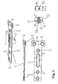
- the plate body 1 according to the invention has an elongated one T-shape with a slightly arched or circular cross-section on.
- the top view in the lower left part of the picture leaves the longitudinal direction Recognize slot 2 and the circumferential conical chamfer 3 formed there.
- the interchangeable cuboid place or spacer 7 has one U-shaped recess 8 such that the side legs 9 of the U-shaped Recess an anti-rotation device and guide in connection with the foot part 6 form the plate body 1.
- a threaded bore 10 is made, which itself is located in the connecting section 11 between the lateral legs 9.
- the screw 12 for fastening the placeholder or spacer 7 indicates one to the threaded part directed, tapered screw head 13 to secure attachment of the spacer or spacer 7 to the plate body 1 guarantee.
- the place or spacers 7 can with the help of the screw 12 on standard plate bodies or those with different lengths of foot parts 6 are attached, the height H of the respective place or spacer 7 of the opening of the Corresponds to an osteotomy wedge cut or is adjusted to the corrective measure.
- Fig. 2 shows a simplified section of the tibia 14 with tibia head 15 and of the femur 16 with an osteotomy wedge.
- the plate body 1 with loosely preassembled place or spacer 7 is inserted with the latter first into the osteotomy wedge opening 17 in order to subsequently determine an optimal position for the fastening bores 5.
- the fastening holes in the head part 4 of the plate body 1 should find their position in the tibia head, so that the consequences of spontaneous fractures in this area are alleviated.
- known self-tapping bone screws are used to fix the plate body 1 in the tibia and the tibia head.
- the place or spacer 7 is finally tightened and fastened to the plate body 1 with the aid of the screw 12 and a suitable tool (not shown).
Abstract
Description
Die Erfindung betrifft eine Vorrichtung zu Stabilisierung der Tibia und/oder des Tibiakopfes nach Osteotomie-Eingriffen, bestehend aus einem langgestreckten Plattenkörper mit Bohrungen zur Aufnahme von Knochenschrauben sowie einem quaderförmigen Platz- oder Abstandshalter, gemäß Oberbegriff des Patentanspruchs 1.The invention relates to a device for stabilizing the tibia and / or the tibia head after osteotomy procedures, consisting of an elongated plate body with holes for receiving bone screws and a cuboid Place or spacer, according to the preamble of claim 1.
Unter Osteotomie wird eine lineare quer-, schräg-, bogen-, zylinder- oder V- bzw. keilförmige Knochendurchtrennung, meist mit anschließender Osteosynthese entweder als vollständige Osteotomie nach Freilegen und Abschieben des Periosts oder als weiche Osteotomie mit Teildurchmeißelung und nachfolgender Frakturierung verstanden. Die Osteotomie findet Anwendung zur Verkürzung, Verlängerung, Achsenumstellung, Rotation oder Abstützung, z.B. als valgisierende und varisierende Osteotomie am koxalen Femurende.A linear transverse, oblique, arch, cylindrical or V or wedge-shaped bone separation, usually with subsequent osteosynthesis either as a complete osteotomy after exposure and removal of the periosteum or as Understand soft osteotomy with partial chiseling and subsequent fracturing. The osteotomy is used for shortening, lengthening, changing the axis, Rotation or support, e.g. as a valgating and varying osteotomy at the koxal end of the femur.
Aus den US-Patentschriften 5,620,448 und 5,749,875 ist ein Knochenplattensystem für die sogenannte Open Wedge Osteotomie vorbekannt.A bone plate system is known from US Pat. Nos. 5,620,448 and 5,749,875 previously known for the so-called open wedge osteotomy.
Die dortige Platte weist eine langgestrecke Form mit an den jeweiligen Enden gegenüberliegenden
Befestigungsbohrungen für Knochenschrauben auf.
Die Platte selbst besitzt eine Erhöhung mit unterschiedlichen Breitenmaßen.The plate there has an elongated shape with fastening bores for bone screws located opposite each other at the respective ends.
The plate itself has an increase with different width dimensions.
Nach Ausführen des Osteotomie-Schnitts und Setzen eines gabelartigen Spreizwerkzeugs wird die aus den zitierten US-Patenten bekannte Platte mit ihrem Fortsatz als Platz- oder Abstandshalter gesetzt und anschließend mit Knochenschrauben an der Tibia fixiert.After performing the osteotomy cut and placing a fork-like spreading tool the plate known from the cited US patents with its extension is called Place or spacer and then with bone screws on the Tibia fixed.
Es hat sich jedoch gezeigt, daß durch die hohen punktuellen Belastungen beim Aufspreizen und Keilsetzen Spontanfrakturen, insbesondere des Tibiakopfes auftreten, verbunden mit dem hierdurch einhergehenden Operationsrisiko. Insofern ist es vielfach erforderlich, vorsorglich oder im Nachgang Fixationsplatten oder -schrauben am Tibiakopf zu setzen.However, it has been shown that the high point loads at Spreading and wedging Spontaneous fractures, especially of the tibia head, occur associated with the associated operational risk. So it is often required, as a precaution or afterwards, fixation plates or screws to put on the tibia head.
Dadurch, daß der Plattenkörper nach US-PS 5,620,448 einen geometrisch festen, unveränderbaren Bezug zwischen Auskragung als Platz- oder Abstandshalter und den Bohrungen zur Aufnahme der Knochenschrauben besitzt, ist es nicht möglich, eine gegebenenfalls günstigere Position zum Setzen der Knochenschrauben auszuwählen.Because the plate body according to US Pat. No. 5,620,448 has a geometrically fixed, unchangeable relation between cantilever as placeholder or spacer and the holes for receiving the bone screws, it is not possible select a possibly more favorable position for setting the bone screws.
Da der bekannte Plattenkörper nebst Platz- und Abstandshalter einstückig ausgebildet ist, muß stets ein Satz von verschiedenen Platten mit unterschiedlichen Abmessungen im Bereich des Platzhalters vorrätig gehalten werden, was zu höheren Kosten führt.Since the known plate body together with space and spacers are made in one piece is always a set of different plates with different dimensions be kept in stock in the placeholder, resulting in higher costs leads.
Aus dem Vorgenannten ist es daher Aufgabe der Erfindung, eine weiterentwickelte Vorrichtung zur Stabilisierung der Tibia und/oder des Tibiakopfes nach Osteotomie-Eingriffen sowie ein Verfahren zur Handhabung einer derartigen Vorrichtung anzugeben, die bzw. das es gestattet, im vorgebbaren Rahmen günstige Befestigungspositionen für die eigentliche Knochenplatte zu finden, und wobei in einfacher Weise eine einzige Knochenplatte mit verschiedenen Abstandshaltern, d.h. Abstandshaltern unterschiedlicher Maße Verwendung finden kann.From the above, it is therefore an object of the invention to develop a further Device for stabilizing the tibia and / or tibia head after osteotomy procedures and to specify a method for handling such a device, which allows favorable mounting positions in the predefinable frame to find for the actual bone plate, and being simple a single bone plate with different spacers, i.e. spacers different dimensions can be used.
Die Lösung der Aufgabe der Erfindung erfolgt vorrichtungsseitig mit einem Gegenstand
nach den Merkmalen des Patentanspruchs 1 sowie mit einem Verfahren in der
Abfolge nach Patentanspruch 10, wobei die Unteransprüche mindestens zweckmäßige
Ausgestaltungen und Weiterbildungen darstellen.The object of the invention is achieved on the device side with an object
according to the features of claim 1 and with a method in the
Sequence according to
Erfindungsgemäß weist die Knochenplatte oder der Plattenkörper ein in Längsachsenrichtung verlaufendes Langloch auf, wobei ein jeweiliger Platz- oder Abstandshalter verschieblich und feststellbar über eine Schraubverbindung im Langloch des Plattenkörpers gehalten ist.According to the invention, the bone plate or the plate body has a direction in the longitudinal axis running elongated hole, with a respective space or spacer movable and lockable via a screw connection in the slot of the Plate body is held.
Der Plattenkörper besitzt bevorzugt eine T-Form und die Platz- oder Abstandshalter sind austauschbar und weisen unterschiedliche Höhenabmessungen je nach Korrekturwinkel auf.The plate body preferably has a T-shape and the spacers or spacers are interchangeable and have different height dimensions depending on the correction angle on.
Der Platz- oder Abstandshalter besitzt eine U-förmige Ausnehmung, wobei die seitlichen, relativ kurzen Schenkel der Ausnehmung den Plattenkörper jeweils seitlich umgreifen, wodurch eine Verdrehsicherung und Führung beim Verschieben im Langloch des Plattenkörpers gebildet ist.The place or spacer has a U-shaped recess, the side, relatively short leg of the recess, the plate body laterally reach around, which prevents rotation and guidance when moving in Elongated hole of the plate body is formed.
Zum Befestigen besitzt der Platz- oder Abstandshalter eine Gewindebohrung, die sich im Verbindungsabschnitt zwischen den seitlichen Schenkeln der Ausnehmung befindet.The spacer or spacer has a threaded hole for fastening itself in the connecting section between the lateral legs of the recess located.
Das Langloch kann zur Oberseite des Plattenkörpers hin gerichtet eine konische Fase, die umlaufend ausgebildet ist, aufweisen.The elongated hole can be conical towards the top of the plate body Chamfer, which is formed all around.
Die Schraube zur Befestigung des Platz- oder Abstandshalters weist einen sich konisch verjüngenden Schraubenkopf oder Schraubenkopfabschnitt auf.The screw for fastening the placeholder or spacer has a conical shape tapered screw head or screw head section.
Im querliegenden Kopfteil des T-förmigen Plattenkörpers sind mindestens zwei Befestigungsbohrungen sowie im langgestreckten Fußteil dem Langloch in Längsachsenrichtung benachbart jeweils mindestens eine Befestigungsbohrung ausgebildet. Bei unterschiedlichen Längenmaßen des Fußteils kann die Anzahl der Befestigungsbohrungen erhöht oder aber auch verringert sein.In the transverse head part of the T-shaped plate body there are at least two mounting holes as well as in the elongated foot part of the elongated hole in the longitudinal axis direction at least one mounting hole is formed adjacent each. With different lengths of the foot part, the number of mounting holes can be increased or reduced.
Die Kopfteilbohrungen dienen einerseits der Befestigung des Plattenkörpers im Tibiakopf und andererseits aber auch zum Stabilisieren der Knochenstruktur des Kopfes selbst. Um den Heilungsprozeß zu fördern, besitzt der Querschnitt des Plattenkörpers eine Bogen- oder Kreissegmentform, wobei der Plattenkörper so gesetzt ist, daß er bezogen auf die Knochenoberfläche konvex angeordnet wird.The head part holes serve on the one hand to fasten the plate body in the tibia head and on the other hand also to stabilize the bone structure of the head itself. In order to promote the healing process, the cross section of the plate body has an arc or circular segment shape, the plate body being set so that it is arranged convex with respect to the bone surface.
Die beschriebene Vorrichtung zur Stabilisierung der Tibia und/oder des Tibiakopfes
nach Osteotomie-Eingriff wird wie folgt verwendet.
Zunächst wird nach Schnittführung und Setzen mindestens eines Spreizkeils je nach
Korrekturmaß ein höhenmäßig entsprechender Platz- oder Abstandshalters ausgewählt
und dieser am Plattenkörper verschieblich befestigt, und zwar unter Zuhilfenahme
der entsprechenden Befestigungsschraube.The described device for stabilizing the tibia and / or the tibia head after osteotomy is used as follows.
First, after cutting and placing at least one expansion wedge, depending on the correction measure, a height-appropriate spacer or spacer is selected and this is slidably attached to the plate body, with the aid of the corresponding fastening screw.
Im Anschluß darin wird der Plattenkörper mit anmontiertem Platz- oder Abstandshalter an der Tibia plaziert und hierbei der Platzhalter in den offenen Ostoetomie-Keilschnitt eingesetzt. Aufgrund der gegebenen Beweglichkeit des Plattenkörpers kann nun eine optimale Befestigungsposition und -lage für die Befestigungsbohrungen, die im Plattenkörper vorgesehen sind, bestimmt werden. Nachdem die aus der Sicht des Operateurs vorteilhafte Position ermittelt wurde, wird mit bevorzugt selbstschneidenden Schrauben der Plattenkörper an der Tibia und dem Tibiakopf fixiert. Ebenso erfolgt ein Anziehen der Schraube zum endgültigen Befestigen des Platzhalters.Subsequently, the plate body with attached space or spacer placed on the tibia and the placeholder in the open osteotomy wedge cut used. Due to the given mobility of the plate body can now determine an optimal mounting position and location for the mounting holes, which are provided in the plate body can be determined. After that from the From the point of view of the surgeon advantageous position has been determined, is preferred self-tapping screws of the plate body on the tibia and the tibia head fixed. The screw is also tightened to finally secure the Placeholder.
Die Konstruktion des T-förmigen Plattenkörpers mit Befestigungsbohrungen, die möglichst weit weg vom aufgetrennten Knochenteil befindlich sind, reduziert die Gefahr unerwünschter weiterer Belastungen im Knochen und fördert den Heilungsprozeß.The construction of the T-shaped plate body with mounting holes that are as far away from the separated bone part as possible Risk of undesirable further stress in the bone and promotes the healing process.
Die Erfindung soll nachstehend anhand eines Ausführungsbeispiels sowie unter Zuhilfenahme von Figuren näher erläutert werden.The invention will be described below using an exemplary embodiment and Figures are explained in more detail.
Hierbei zeigen:
Der erfindungsgemäße Plattenkörper 1 weist, wie in der Fig. 1 ersichtlich, eine langgestreckte T-Form mit einem leicht gewölbten bzw. kreisbogenförmigen Querschnitt auf.The plate body 1 according to the invention, as can be seen in FIG. 1, has an elongated one T-shape with a slightly arched or circular cross-section on.
Die Draufsicht im linken unteren Bildteil läßt das in Längsrichtung verlaufende
Langloch 2 und die dort ausgebildete umlaufende konische Fase 3 erkennen.The top view in the lower left part of the picture leaves the longitudinal direction
Recognize
Kopfseitig, d.h. im querliegenden Kopfteil 4 des Plattenkörpers 1 sind zwei
beabstandete Befestigungsbohrungen 5 vorgesehen. Weitere Befestigungsbohrungen
befinden sich dem Langloch 2 benachbart im Fußteil 6 des Plattenkörpers 1.Upside, i.e. in the
Der austauschbar gestaltete quaderförmige Platz- oder Abstandshalter 7 besitzt eine
U-förmige Ausnehmung 8 dergestalt, daß die seitlichen Schenkel 9 der U-förmigen
Ausnehmung eine Verdrehsicherung und Führung in Verbindung mit dem Fußteil 6
des Plattenkörpers 1 bilden.The interchangeable cuboid place or
Im Platz- oder Abstandshalter 7 ist eine Gewindebohrung 10 eingebracht, die sich
im Verbindungsabschnitt 11 zwischen den seitlichen Schenkeln 9 befindet. In the place or
Die Schraube 12 zur Befestigung des Platz- oder Abstandshalters 7 weist einen hin
zum Gewindeteil gerichteten, sich konisch verjüngenden Schraubenkopf 13 auf, um
eine sichere Befestigung des Platz- oder Abstandshalters 7 am Plattenkörper 1 zu
gewährleisten.The
Die Platz- oder Abstandshalter 7 können mit Hilfe der Schraube 12 an Standard-Plattenkörpern
oder solchen mit unterschiedlich langen Fußteilen 6 befestigt werden,
wobei die Höhe H des jeweiligen Platz- oder Abstandshalters 7 der Öffnung des
Osteotomie-Keilschnitts entspricht bzw. auf das Korrekturmaß abgestimmt wird.The place or
Fig. 2 stellt stark vereinfacht einen Abschnitt der Tibia 14 mit Tibiakopf 15 sowie
des Femur 16 mit ausgeführtem Osteotomie-Keil dar.Fig. 2 shows a simplified section of the
Der Plattenkörper 1 mit lose vormontiertem Platz- oder Abstandshalter 7 wird mit
letzterem voran in die Osteotomie-Keilöffnung 17 eingesetzt, um hiernach eine optimale
Position für die Befestigungsbohrungen 5 zu ermitteln.
Grundsätzlich sollen die Befestigungsbohrungen im Kopfteil 4 des Plattenkörpers 1
ihre Lage im Tibiakopf finden, so daß die Folgen von Spontanfrakturen in diesem
Bereich gemildert werden.
Nachdem die gewünschte Befestigungsposition ermittelt wurde, werden an sich bekannte
selbstschneidende Knochenschrauben zum Fixieren des Plattenkörpers 1 in
der Tibia und dem Tibiakopf genutzt. Ebenso erfolgt ein endgültiges Anziehen und
Befestigen des Platz- oder Abstandshalters 7 am Plattenkörper 1 mit Hilfe der
Schraube 12 und eines geeigneten (nicht gezeigten) Werkzeugs.The plate body 1 with loosely preassembled place or
Basically, the fastening holes in the
After the desired fastening position has been determined, known self-tapping bone screws are used to fix the plate body 1 in the tibia and the tibia head. Likewise, the place or
- 11
- Plattenkörperplate body
- 22
- LanglochLong hole
- 33
- konische Faseconical bevel
- 44
- Kopfteilheadboard
- 55
- Befestigungsbohrungenmounting holes
- 66
- Fußteilfootboard
- 77
- Platz- oder AbstandshalterSpacers or spacers
- 88th
- Ausnehmung im Platz- oder AbstandshalterRecess in the spacer or spacer
- 99
- seitliche Schenkel der U-förmigen Ausnehmung lateral legs of the U-shaped recess
- 1010
- Gewindebohrungthreaded hole
- 1111
- Verbindungsabschnittconnecting portion
- 1212
- Schraube für PlatzhalterPlaceholder screw
- 1313
- Schraubenkopfscrew head
- 1414
- Tibiatibia
- 1515
- Tibiakopftibia
- 1616
- Femurfemur
- 1717
- Osteotomie-KeilOsteotomy Wedge
Claims (8)
dadurch gekennzeichnet, dass
der Platz- oder Abstandshalter (7) eine U-förmige Ausnehmung (8) aufweist, wobei die seitlichen Schenkel (9) der Ausnehmung (8) den Plattenkörper (1) umgreifen, wodurch eine Verdrehsicherung und Führung gebildet ist.Device for stabilizing the tibia and / or the tibia head after osteotomy procedures, consisting of an elongated plate body with holes for receiving bone screws and a cuboid spacer or spacer, the plate body having an elongated hole running in the longitudinal axis direction, the spacer or spacer being displaceable and is held in place by means of a screw connection in the elongated hole of the plate body and the space or spacer has different, in particular height, dimensions and can be replaced,
characterized in that
the place or spacer (7) has a U-shaped recess (8), the lateral legs (9) of the recess (8) engaging around the plate body (1), whereby an anti-twist device and a guide are formed.
dadurch gekennzeichnet, dass
der Platz- oder Abstandshalter (7) eine Gewindebohrung (10) aufweist, die sich im Verbindungsabschnitt (11) zwischen den seitlichen Schenkeln (9) der Ausnehmung (8) befindet.Device according to claim 1,
characterized in that
the spacer (7) has a threaded bore (10) which is located in the connecting section (11) between the lateral legs (9) of the recess (8).
dadurch gekennzeichnet, dass
das Langloch (2) eine zur Oberseite des Plattenkörpers (1) verlaufende konische Fase (3) aufweist.Device according to claim 1 or 2,
characterized in that
the elongated hole (2) has a conical chamfer (3) running to the top of the plate body (1).
dadurch gekennzeichnet, dass
die Schraube (12) zur Befestigung des Platz- oder Abstandshalters (7) einen sich konisch verjüngenden Schraubenkopf (13) oder Schraubenkopfabschnitt besitzt.Device according to claim 3,
characterized in that
the screw (12) for fastening the spacer (7) has a conically tapering screw head (13) or screw head section.
dadurch gekennzeichnet, dass
der Plattenkörper (1) eine T-Form aufweist, wobei im querliegenden Kopfteil (4) mindestens zwei Befestigungsbohrungen (5) sowie im langgestreckten Fußteil (6) dem Langloch (2) in Längsachsenrichtung benachbart jeweils mindestens eine weitere Befestigungsbohrung (5) ausgebildet ist. Device according to one of the preceding claims,
characterized in that
the plate body (1) has a T-shape, at least two fastening bores (5) being formed in the transverse head part (4) and at least two fastening bores (5) adjacent to the elongated hole (2) in the longitudinal axis direction in the elongated foot part (6).
dadurch gekennzeichnet, dass
die Kopfteilbohrungen (5) der Befestigung des Plattenkörpers (1) im Tibiakopf (15) und dem Stabilisieren der Knochenstruktur des Kopfes selbst dienen.Device according to claim 5,
characterized in that
the head part bores (5) serve to fasten the plate body (1) in the tibia head (15) and to stabilize the bone structure of the head itself.
dadurch gekennzeichnet, dass
der Querschnitt des Plattenkörpers (1) eine Bogen- oder Kreissegmentform besitzt.Device according to one of the preceding claims,
characterized in that
the cross section of the plate body (1) has an arc or circular segment shape.
dadurch gekennzeichnet, dass
nach Schnittführung und Setzen mindestens eines Spreizkeils je nach Korrekturmaß ein Platz- oder Abstandshalter ausgewählt und dieser am Plattenkörper verschieblich befestigt wird, der Plattenkörper mit Platz- oder Abstandshalter an der Tibia plaziert und hierbei der Platzhalter in den offenen Osteotomie-Keilschnitt eingesetzt wird, hiernach über den noch verschieblichen Plattenkörper eine optimale Position ermittelt und über die Befestigungsbohrungen der Plattenkörper mit bevorzugt selbstschneidenden Knochenschrauben an der Tibia und dem Tibiakopf fixiert wird sowie ein Anziehen der Schraube des Platzhalters erfolgt.Method for stabilizing the tibia and / or the tibia head after osteotomy surgery with a device according to one of claims 1 to 7,
characterized in that
After cutting and inserting at least one expansion wedge, depending on the correction, a placeholder or spacer is selected and this is slidably attached to the plate body, the plate body is placed with a placeholder or spacer on the tibia and the placeholder is inserted into the open osteotomy wedge cut, hereinafter about an optimal position is determined for the still displaceable plate body and is fixed to the tibia and the tibia head by means of the fastening holes in the plate body using preferably self-tapping bone screws and the screw of the placeholder is tightened.
Applications Claiming Priority (2)
| Application Number | Priority Date | Filing Date | Title |
|---|---|---|---|
| DE10153467A DE10153467B4 (en) | 2001-10-30 | 2001-10-30 | Device for stabilizing the tibia and / or tibial plateau following osteotomy procedures |
| DE10153467 | 2001-10-30 |
Publications (3)
| Publication Number | Publication Date |
|---|---|
| EP1308135A2 true EP1308135A2 (en) | 2003-05-07 |
| EP1308135A3 EP1308135A3 (en) | 2003-12-03 |
| EP1308135B1 EP1308135B1 (en) | 2004-11-24 |
Family
ID=7704175
Family Applications (1)
| Application Number | Title | Priority Date | Filing Date |
|---|---|---|---|
| EP02021293A Expired - Lifetime EP1308135B1 (en) | 2001-10-30 | 2002-09-19 | Device for stabilising the tibia and/or the head of the tibia after osteotomy surgery |
Country Status (4)
| Country | Link |
|---|---|
| EP (1) | EP1308135B1 (en) |
| AT (1) | ATE283000T1 (en) |
| DE (2) | DE10153467B4 (en) |
| ES (1) | ES2232705T3 (en) |
Cited By (14)
| Publication number | Priority date | Publication date | Assignee | Title |
|---|---|---|---|---|
| FR2906126A1 (en) * | 2006-09-22 | 2008-03-28 | Philippe Mengus | Osteosynthesis device for securing osteotomy tibia opening, has groove that vertically slides to permit different angulations adjustment relative to deformation correction, and fixation of selected angle by blocking device using screws |
| US20080195099A1 (en) * | 2007-02-13 | 2008-08-14 | The Brigham And Women's Hospital, Inc. | Osteotomy system |
| WO2010149702A1 (en) * | 2009-06-25 | 2010-12-29 | Universität Rostock | Repositioning device for the handling of distal radius fractures by means of a t-shaped osteosynthesis plate |
| US8231662B2 (en) | 2006-10-17 | 2012-07-31 | Acumed Llc | Bone fixation with a strut-stabilized bone plate |
| CN103417284A (en) * | 2013-09-04 | 2013-12-04 | 王晓宁 | Tibial plateau back outer side bone plate |
| WO2014147604A3 (en) * | 2013-03-19 | 2014-12-18 | Quadrante Do Futuro, Unipessoal Lda | Dynamic osteotomy plate including devices, apparatus and methods using such a plate |
| CN105342682A (en) * | 2015-11-30 | 2016-02-24 | 泰州市人民医院 | Bone fracture plate device for distal femur fracture |
| CN106170259A (en) * | 2014-04-18 | 2016-11-30 | 白惠善 | Fixing utensil for opening hto art |
| JP2017511194A (en) * | 2014-04-18 | 2017-04-20 | ベク ヘソンPAIK, Hae Sun | Fixing device for open wedge high tibial osteotomy |
| RU2636899C2 (en) * | 2015-08-21 | 2017-11-28 | "ЦхМ" Сп. з о.о. | Instrument for osteotomy |
| JP2017537724A (en) * | 2014-12-16 | 2017-12-21 | ベク ヘソンPAIK, Hae Sun | Fixation device for open distal tibial osteotomy |
| WO2018144818A1 (en) * | 2017-02-06 | 2018-08-09 | Biomet Manufacturing, Llc | Adjustable wedge |
| US10143503B2 (en) | 2014-03-26 | 2018-12-04 | Olympus Terumo Biomaterials Corp. | Bone plate and bone plate system |
| US10159517B2 (en) | 2014-07-07 | 2018-12-25 | Stryker European Holdings I, Llc | Bone plate with attachable wedge |
Families Citing this family (3)
| Publication number | Priority date | Publication date | Assignee | Title |
|---|---|---|---|---|
| DE102008008275A1 (en) | 2008-02-07 | 2009-08-20 | Hägele GmbH | Fan blade for fan wheels, particularly axial blowers, is made of material from radially outside, where material is removed during circulation of fan wheel by contacting to fixed frame |
| DE102011017033B4 (en) * | 2010-10-25 | 2015-06-18 | Königsee Implantate GmbH | Foot bone plate for osteosynthesis and / or fixation |
| ES2386913B1 (en) * | 2011-02-09 | 2013-10-17 | Universitat Autònoma De Barcelona | DEVICE FOR THE ADVANCE OF TIBIAL TUBEROSITY IN THE DOG. |
Citations (4)
| Publication number | Priority date | Publication date | Assignee | Title |
|---|---|---|---|---|
| WO1996014802A1 (en) * | 1994-11-10 | 1996-05-23 | Georges Kehyayan | Device for temporarily locking two portions of a bone |
| FR2727005A1 (en) * | 1994-11-18 | 1996-05-24 | Euros Sa | Anterior stabiliser for cervical section of spine |
| FR2785519A1 (en) * | 1998-11-10 | 2000-05-12 | Advanced Technical Fabrication | Osteosynthesis plate has interchangeable wedge mounted on plate with faces engaging opposed faces of osteotomy |
| DE10015734A1 (en) * | 2000-03-02 | 2001-09-13 | Med Medical Engineering Dev Lt | Screw connection for osteosynthesis, e.g. to fix tibia head plate; has screw with conical head and ring, which can be moved in bearing ring, but is spread by screw head to fix angle of implant |
Family Cites Families (3)
| Publication number | Priority date | Publication date | Assignee | Title |
|---|---|---|---|---|
| US5620448A (en) * | 1995-03-24 | 1997-04-15 | Arthrex, Inc. | Bone plate system for opening wedge proximal tibial osteotomy |
| EP0773004A1 (en) * | 1995-11-07 | 1997-05-14 | IMPLANTS ORTHOPEDIQUES TOUTES APPLICATIONS, S.A.R.L. dite: | Osteotomy plate for angle correction |
| US5827286A (en) * | 1997-02-14 | 1998-10-27 | Incavo; Stephen J. | Incrementally adjustable tibial osteotomy fixation device and method |
-
2001
- 2001-10-30 DE DE10153467A patent/DE10153467B4/en not_active Expired - Fee Related
-
2002
- 2002-09-19 ES ES02021293T patent/ES2232705T3/en not_active Expired - Lifetime
- 2002-09-19 EP EP02021293A patent/EP1308135B1/en not_active Expired - Lifetime
- 2002-09-19 AT AT02021293T patent/ATE283000T1/en active
- 2002-09-19 DE DE50201613T patent/DE50201613D1/en not_active Expired - Lifetime
Patent Citations (4)
| Publication number | Priority date | Publication date | Assignee | Title |
|---|---|---|---|---|
| WO1996014802A1 (en) * | 1994-11-10 | 1996-05-23 | Georges Kehyayan | Device for temporarily locking two portions of a bone |
| FR2727005A1 (en) * | 1994-11-18 | 1996-05-24 | Euros Sa | Anterior stabiliser for cervical section of spine |
| FR2785519A1 (en) * | 1998-11-10 | 2000-05-12 | Advanced Technical Fabrication | Osteosynthesis plate has interchangeable wedge mounted on plate with faces engaging opposed faces of osteotomy |
| DE10015734A1 (en) * | 2000-03-02 | 2001-09-13 | Med Medical Engineering Dev Lt | Screw connection for osteosynthesis, e.g. to fix tibia head plate; has screw with conical head and ring, which can be moved in bearing ring, but is spread by screw head to fix angle of implant |
Cited By (25)
| Publication number | Priority date | Publication date | Assignee | Title |
|---|---|---|---|---|
| FR2906126A1 (en) * | 2006-09-22 | 2008-03-28 | Philippe Mengus | Osteosynthesis device for securing osteotomy tibia opening, has groove that vertically slides to permit different angulations adjustment relative to deformation correction, and fixation of selected angle by blocking device using screws |
| US8231662B2 (en) | 2006-10-17 | 2012-07-31 | Acumed Llc | Bone fixation with a strut-stabilized bone plate |
| US20080195099A1 (en) * | 2007-02-13 | 2008-08-14 | The Brigham And Women's Hospital, Inc. | Osteotomy system |
| WO2010149702A1 (en) * | 2009-06-25 | 2010-12-29 | Universität Rostock | Repositioning device for the handling of distal radius fractures by means of a t-shaped osteosynthesis plate |
| US20120116401A1 (en) * | 2009-06-25 | 2012-05-10 | Georg Gradl | Repositioning device for the handling of distal radius fractures by means of a t-shaped osteosynthesis plate |
| WO2014147604A3 (en) * | 2013-03-19 | 2014-12-18 | Quadrante Do Futuro, Unipessoal Lda | Dynamic osteotomy plate including devices, apparatus and methods using such a plate |
| CN103417284A (en) * | 2013-09-04 | 2013-12-04 | 王晓宁 | Tibial plateau back outer side bone plate |
| US10143503B2 (en) | 2014-03-26 | 2018-12-04 | Olympus Terumo Biomaterials Corp. | Bone plate and bone plate system |
| US10245089B2 (en) | 2014-04-18 | 2019-04-02 | Hae Sun Paik | Fixing tool for open-wedge high tibial osteotomy |
| CN106170259A (en) * | 2014-04-18 | 2016-11-30 | 白惠善 | Fixing utensil for opening hto art |
| JP2017514566A (en) * | 2014-04-18 | 2017-06-08 | ベク ヘソンPAIK, Hae Sun | Fixing device for open wedge high tibial osteotomy |
| US10441331B2 (en) | 2014-04-18 | 2019-10-15 | Hae Sun Paik | Fixing tool for open-wedge high tibial osteotomy |
| CN106170259B (en) * | 2014-04-18 | 2019-06-14 | 白惠善 | Fixed appliance for opening high tibial osteotomy art |
| JP2017511194A (en) * | 2014-04-18 | 2017-04-20 | ベク ヘソンPAIK, Hae Sun | Fixing device for open wedge high tibial osteotomy |
| US10159517B2 (en) | 2014-07-07 | 2018-12-25 | Stryker European Holdings I, Llc | Bone plate with attachable wedge |
| EP3235459A4 (en) * | 2014-12-16 | 2018-08-22 | Paik, Hae Sun | Fixing instrument for open-type distal tibial osteotomy |
| JP2017537724A (en) * | 2014-12-16 | 2017-12-21 | ベク ヘソンPAIK, Hae Sun | Fixation device for open distal tibial osteotomy |
| US10499963B2 (en) | 2014-12-16 | 2019-12-10 | Hae Sun Paik | Fixing instrument for open-type distal tibial osteotomy |
| RU2636899C2 (en) * | 2015-08-21 | 2017-11-28 | "ЦхМ" Сп. з о.о. | Instrument for osteotomy |
| CN105342682A (en) * | 2015-11-30 | 2016-02-24 | 泰州市人民医院 | Bone fracture plate device for distal femur fracture |
| CN105342682B (en) * | 2015-11-30 | 2017-08-25 | 泰州市人民医院 | A kind of synthetism panel assembly for Methods for Distal Femoral Fractures |
| WO2018144818A1 (en) * | 2017-02-06 | 2018-08-09 | Biomet Manufacturing, Llc | Adjustable wedge |
| CN110267611A (en) * | 2017-02-06 | 2019-09-20 | 拜欧米特制造有限责任公司 | Adjustable voussoir |
| US10543028B2 (en) | 2017-02-06 | 2020-01-28 | Biomet Manufacturing, Llc | Adjustable wedge |
| CN110267611B (en) * | 2017-02-06 | 2021-11-12 | 拜欧米特制造有限责任公司 | Adjustable wedge block |
Also Published As
| Publication number | Publication date |
|---|---|
| DE10153467B4 (en) | 2006-05-24 |
| ES2232705T3 (en) | 2005-06-01 |
| DE50201613D1 (en) | 2004-12-30 |
| ATE283000T1 (en) | 2004-12-15 |
| EP1308135A3 (en) | 2003-12-03 |
| DE10153467A1 (en) | 2003-05-15 |
| EP1308135B1 (en) | 2004-11-24 |
Similar Documents
| Publication | Publication Date | Title |
|---|---|---|
| EP1308135B1 (en) | Device for stabilising the tibia and/or the head of the tibia after osteotomy surgery | |
| EP0751753B1 (en) | Positioning and support device for the spinal column | |
| EP0374084B1 (en) | Sliding hole plate for osteosynthesis | |
| DE102005032026B3 (en) | Osteosynthesis plate for treatment of mandibular fractures, has passage openings with angle adjustments with respect to one of longitudinal axes within plane, where adjustments deviate from each other at preset value with respect to axis | |
| EP1482847B1 (en) | Implant for the dynamic fixation of a corrective osteotomy | |
| EP0487830A1 (en) | Implant for correction of the humain spinal column | |
| DE19750493A1 (en) | Fracture stabilization implant and screw for use in surgery | |
| EP1684651A1 (en) | Plate used to stabilise distal radius fractures | |
| DE202012103384U1 (en) | Pelvic ring implant | |
| EP0736286A2 (en) | Osteosynthetic device for treating subtrochanteric and pertrochanteric fractures and fractures of the neck of the femur | |
| DE4328015A1 (en) | Device for treating bones | |
| DE2246274A1 (en) | DEVICE FOR TREATMENT OF BROKEN TUBE BONES BY AXIAL PRESSURE OSTEOSYNTHESIS | |
| DE3032237A1 (en) | Bar implant for surgical scoliosis treatment - has hook secured to bar by friction and engaging vertebrae | |
| DE3807346C1 (en) | Implant for repositioning and stabilisation of bones | |
| DE2946784A1 (en) | DEVICE FOR DETERMINING BROKEN BONES | |
| DE102005043281A1 (en) | Bone plate for maintaining proximal humerus fracture, has heading section whose region overlapping shank part in dorsal direction is larger than region of section overlapping shank part in ventral direction | |
| EP1679044B1 (en) | Set for creation of an implant for osteosynthesis | |
| EP2445430B1 (en) | Repositioning device for the handling of distal radius fractures by means of a t-shaped osteosynthesis plate | |
| DE10356904B4 (en) | Plate for stabilizing distal radius fractures comprises an anatomically performed plate part having a triangular shape which is irregular | |
| DE102011113235B4 (en) | Rod extension system for the extension of an existing screw-rod implant for fixation of the spine | |
| DE102015001296B4 (en) | Implant for temporary Epiphyseodese or Hemiepiphyseodese | |
| EP3045130B1 (en) | Implant for temporary epiphysiodesis or hemiepiphysiodesis | |
| DD278491A1 (en) | MARK SPACE LOCK BRAND | |
| EP1694215B1 (en) | Instrument for the insertion of an intervertebral articular prosthesis | |
| EP2750616B1 (en) | Device for fixing a bone fractured in the femoral neck region |
Legal Events
| Date | Code | Title | Description |
|---|---|---|---|
| PUAI | Public reference made under article 153(3) epc to a published international application that has entered the european phase |
Free format text: ORIGINAL CODE: 0009012 |
|
| AK | Designated contracting states |
Designated state(s): AT BE BG CH CY CZ DE DK EE ES FI FR GB GR IE IT LI LU MC NL PT SE SK TR |
|
| AX | Request for extension of the european patent |
Extension state: AL LT LV MK RO SI |
|
| PUAL | Search report despatched |
Free format text: ORIGINAL CODE: 0009013 |
|
| AK | Designated contracting states |
Kind code of ref document: A3 Designated state(s): AT BE BG CH CY CZ DE DK EE ES FI FR GB GR IE IT LI LU MC NL PT SE SK TR |
|
| AX | Request for extension of the european patent |
Extension state: AL LT LV MK RO SI |
|
| 17P | Request for examination filed |
Effective date: 20031107 |
|
| GRAP | Despatch of communication of intention to grant a patent |
Free format text: ORIGINAL CODE: EPIDOSNIGR1 |
|
| AKX | Designation fees paid | ||
| GRAS | Grant fee paid |
Free format text: ORIGINAL CODE: EPIDOSNIGR3 |
|
| RBV | Designated contracting states (corrected) |
Designated state(s): AT BE BG CH CY CZ DE DK EE ES FI FR GB GR IE IT LI LU MC NL PT SE SK TR |
|
| REG | Reference to a national code |
Ref country code: DE Ref legal event code: 8566 |
|
| GRAA | (expected) grant |
Free format text: ORIGINAL CODE: 0009210 |
|
| AK | Designated contracting states |
Kind code of ref document: B1 Designated state(s): AT BE BG CH CY CZ DE DK EE ES FI FR GB GR IE IT LI LU MC NL PT SE SK TR |
|
| PG25 | Lapsed in a contracting state [announced via postgrant information from national office to epo] |
Ref country code: IT Free format text: LAPSE BECAUSE OF FAILURE TO SUBMIT A TRANSLATION OF THE DESCRIPTION OR TO PAY THE FEE WITHIN THE PRESCRIBED TIME-LIMIT;WARNING: LAPSES OF ITALIAN PATENTS WITH EFFECTIVE DATE BEFORE 2007 MAY HAVE OCCURRED AT ANY TIME BEFORE 2007. THE CORRECT EFFECTIVE DATE MAY BE DIFFERENT FROM THE ONE RECORDED. Effective date: 20041124 Ref country code: NL Free format text: LAPSE BECAUSE OF FAILURE TO SUBMIT A TRANSLATION OF THE DESCRIPTION OR TO PAY THE FEE WITHIN THE PRESCRIBED TIME-LIMIT Effective date: 20041124 Ref country code: TR Free format text: LAPSE BECAUSE OF FAILURE TO SUBMIT A TRANSLATION OF THE DESCRIPTION OR TO PAY THE FEE WITHIN THE PRESCRIBED TIME-LIMIT Effective date: 20041124 Ref country code: SK Free format text: LAPSE BECAUSE OF FAILURE TO SUBMIT A TRANSLATION OF THE DESCRIPTION OR TO PAY THE FEE WITHIN THE PRESCRIBED TIME-LIMIT Effective date: 20041124 Ref country code: FR Free format text: LAPSE BECAUSE OF FAILURE TO SUBMIT A TRANSLATION OF THE DESCRIPTION OR TO PAY THE FEE WITHIN THE PRESCRIBED TIME-LIMIT Effective date: 20041124 Ref country code: EE Free format text: LAPSE BECAUSE OF FAILURE TO SUBMIT A TRANSLATION OF THE DESCRIPTION OR TO PAY THE FEE WITHIN THE PRESCRIBED TIME-LIMIT Effective date: 20041124 Ref country code: BG Free format text: LAPSE BECAUSE OF FAILURE TO SUBMIT A TRANSLATION OF THE DESCRIPTION OR TO PAY THE FEE WITHIN THE PRESCRIBED TIME-LIMIT Effective date: 20041124 |
|
| REG | Reference to a national code |
Ref country code: GB Ref legal event code: FG4D Free format text: NOT ENGLISH |
|
| REG | Reference to a national code |
Ref country code: CH Ref legal event code: NV Representative=s name: ISLER & PEDRAZZINI AG Ref country code: CH Ref legal event code: EP Ref country code: SE Ref legal event code: TRGR |
|
| REF | Corresponds to: |
Ref document number: 50201613 Country of ref document: DE Date of ref document: 20041230 Kind code of ref document: P |
|
| REG | Reference to a national code |
Ref country code: IE Ref legal event code: FG4D Free format text: GERMAN |
|
| PG25 | Lapsed in a contracting state [announced via postgrant information from national office to epo] |
Ref country code: DK Free format text: LAPSE BECAUSE OF FAILURE TO SUBMIT A TRANSLATION OF THE DESCRIPTION OR TO PAY THE FEE WITHIN THE PRESCRIBED TIME-LIMIT Effective date: 20050224 Ref country code: GR Free format text: LAPSE BECAUSE OF FAILURE TO SUBMIT A TRANSLATION OF THE DESCRIPTION OR TO PAY THE FEE WITHIN THE PRESCRIBED TIME-LIMIT Effective date: 20050224 |
|
| NLV1 | Nl: lapsed or annulled due to failure to fulfill the requirements of art. 29p and 29m of the patents act | ||
| REG | Reference to a national code |
Ref country code: ES Ref legal event code: FG2A Ref document number: 2232705 Country of ref document: ES Kind code of ref document: T3 |
|
| PGFP | Annual fee paid to national office [announced via postgrant information from national office to epo] |
Ref country code: CZ Payment date: 20050831 Year of fee payment: 4 |
|
| PG25 | Lapsed in a contracting state [announced via postgrant information from national office to epo] |
Ref country code: CY Free format text: LAPSE BECAUSE OF FAILURE TO SUBMIT A TRANSLATION OF THE DESCRIPTION OR TO PAY THE FEE WITHIN THE PRESCRIBED TIME-LIMIT Effective date: 20050919 |
|
| PGFP | Annual fee paid to national office [announced via postgrant information from national office to epo] |
Ref country code: IE Payment date: 20050920 Year of fee payment: 4 |
|
| PGFP | Annual fee paid to national office [announced via postgrant information from national office to epo] |
Ref country code: FI Payment date: 20050923 Year of fee payment: 4 |
|
| PG25 | Lapsed in a contracting state [announced via postgrant information from national office to epo] |
Ref country code: MC Free format text: LAPSE BECAUSE OF NON-PAYMENT OF DUE FEES Effective date: 20050930 Ref country code: LU Free format text: LAPSE BECAUSE OF NON-PAYMENT OF DUE FEES Effective date: 20050930 Ref country code: BE Free format text: LAPSE BECAUSE OF NON-PAYMENT OF DUE FEES Effective date: 20050930 |
|
| PLBE | No opposition filed within time limit |
Free format text: ORIGINAL CODE: 0009261 |
|
| STAA | Information on the status of an ep patent application or granted ep patent |
Free format text: STATUS: NO OPPOSITION FILED WITHIN TIME LIMIT |
|
| 26N | No opposition filed |
Effective date: 20050825 |
|
| EN | Fr: translation not filed | ||
| PG25 | Lapsed in a contracting state [announced via postgrant information from national office to epo] |
Ref country code: CZ Free format text: LAPSE BECAUSE OF NON-PAYMENT OF DUE FEES Effective date: 20060919 Ref country code: IE Free format text: LAPSE BECAUSE OF NON-PAYMENT OF DUE FEES Effective date: 20060919 Ref country code: FI Free format text: LAPSE BECAUSE OF NON-PAYMENT OF DUE FEES Effective date: 20060919 |
|
| REG | Reference to a national code |
Ref country code: IE Ref legal event code: MM4A |
|
| PGFP | Annual fee paid to national office [announced via postgrant information from national office to epo] |
Ref country code: ES Payment date: 20070917 Year of fee payment: 6 |
|
| REG | Reference to a national code |
Ref country code: CH Ref legal event code: PCAR Free format text: ISLER & PEDRAZZINI AG;POSTFACH 1772;8027 ZUERICH (CH) |
|
| BERE | Be: lapsed |
Owner name: *KONIGSEE IMPLANTATE UND INSTRUMENTE ZUR OSTHEOSYN Effective date: 20050930 |
|
| PG25 | Lapsed in a contracting state [announced via postgrant information from national office to epo] |
Ref country code: PT Free format text: LAPSE BECAUSE OF NON-PAYMENT OF DUE FEES Effective date: 20050424 |
|
| PGFP | Annual fee paid to national office [announced via postgrant information from national office to epo] |
Ref country code: SE Payment date: 20070903 Year of fee payment: 6 |
|
| PGFP | Annual fee paid to national office [announced via postgrant information from national office to epo] |
Ref country code: GB Payment date: 20071001 Year of fee payment: 6 |
|
| GBPC | Gb: european patent ceased through non-payment of renewal fee |
Effective date: 20080919 |
|
| REG | Reference to a national code |
Ref country code: ES Ref legal event code: FD2A Effective date: 20080920 |
|
| PG25 | Lapsed in a contracting state [announced via postgrant information from national office to epo] |
Ref country code: GB Free format text: LAPSE BECAUSE OF NON-PAYMENT OF DUE FEES Effective date: 20080919 |
|
| PG25 | Lapsed in a contracting state [announced via postgrant information from national office to epo] |
Ref country code: ES Free format text: LAPSE BECAUSE OF NON-PAYMENT OF DUE FEES Effective date: 20080920 |
|
| PG25 | Lapsed in a contracting state [announced via postgrant information from national office to epo] |
Ref country code: SE Free format text: LAPSE BECAUSE OF NON-PAYMENT OF DUE FEES Effective date: 20080920 |
|
| PGFP | Annual fee paid to national office [announced via postgrant information from national office to epo] |
Ref country code: CH Payment date: 20100930 Year of fee payment: 9 |
|
| PGFP | Annual fee paid to national office [announced via postgrant information from national office to epo] |
Ref country code: AT Payment date: 20100927 Year of fee payment: 9 |
|
| PGFP | Annual fee paid to national office [announced via postgrant information from national office to epo] |
Ref country code: DE Payment date: 20101129 Year of fee payment: 9 |
|
| REG | Reference to a national code |
Ref country code: CH Ref legal event code: PL |
|
| REG | Reference to a national code |
Ref country code: DE Ref legal event code: R119 Ref document number: 50201613 Country of ref document: DE Effective date: 20120403 |
|
| PG25 | Lapsed in a contracting state [announced via postgrant information from national office to epo] |
Ref country code: LI Free format text: LAPSE BECAUSE OF NON-PAYMENT OF DUE FEES Effective date: 20110930 Ref country code: CH Free format text: LAPSE BECAUSE OF NON-PAYMENT OF DUE FEES Effective date: 20110930 Ref country code: DE Free format text: LAPSE BECAUSE OF NON-PAYMENT OF DUE FEES Effective date: 20120403 |
|
| REG | Reference to a national code |
Ref country code: AT Ref legal event code: MM01 Ref document number: 283000 Country of ref document: AT Kind code of ref document: T Effective date: 20110919 |
|
| PG25 | Lapsed in a contracting state [announced via postgrant information from national office to epo] |
Ref country code: AT Free format text: LAPSE BECAUSE OF NON-PAYMENT OF DUE FEES Effective date: 20110919 |
|
| P01 | Opt-out of the competence of the unified patent court (upc) registered |
Effective date: 20230531 |