EP1308182A2 - Implantable cardiac stimulation device - Google Patents
Implantable cardiac stimulation device Download PDFInfo
- Publication number
- EP1308182A2 EP1308182A2 EP02257567A EP02257567A EP1308182A2 EP 1308182 A2 EP1308182 A2 EP 1308182A2 EP 02257567 A EP02257567 A EP 02257567A EP 02257567 A EP02257567 A EP 02257567A EP 1308182 A2 EP1308182 A2 EP 1308182A2
- Authority
- EP
- European Patent Office
- Prior art keywords
- patient
- timing
- timing parameters
- stimulation device
- parameters
- Prior art date
- Legal status (The legal status is an assumption and is not a legal conclusion. Google has not performed a legal analysis and makes no representation as to the accuracy of the status listed.)
- Ceased
Links
Images


Classifications
-
- A—HUMAN NECESSITIES
- A61—MEDICAL OR VETERINARY SCIENCE; HYGIENE
- A61N—ELECTROTHERAPY; MAGNETOTHERAPY; RADIATION THERAPY; ULTRASOUND THERAPY
- A61N1/00—Electrotherapy; Circuits therefor
- A61N1/18—Applying electric currents by contact electrodes
- A61N1/32—Applying electric currents by contact electrodes alternating or intermittent currents
- A61N1/36—Applying electric currents by contact electrodes alternating or intermittent currents for stimulation
- A61N1/362—Heart stimulators
- A61N1/3627—Heart stimulators for treating a mechanical deficiency of the heart, e.g. congestive heart failure or cardiomyopathy
-
- A—HUMAN NECESSITIES
- A61—MEDICAL OR VETERINARY SCIENCE; HYGIENE
- A61N—ELECTROTHERAPY; MAGNETOTHERAPY; RADIATION THERAPY; ULTRASOUND THERAPY
- A61N1/00—Electrotherapy; Circuits therefor
- A61N1/18—Applying electric currents by contact electrodes
- A61N1/32—Applying electric currents by contact electrodes alternating or intermittent currents
- A61N1/36—Applying electric currents by contact electrodes alternating or intermittent currents for stimulation
- A61N1/362—Heart stimulators
- A61N1/365—Heart stimulators controlled by a physiological parameter, e.g. heart potential
- A61N1/36514—Heart stimulators controlled by a physiological parameter, e.g. heart potential controlled by a physiological quantity other than heart potential, e.g. blood pressure
- A61N1/36521—Heart stimulators controlled by a physiological parameter, e.g. heart potential controlled by a physiological quantity other than heart potential, e.g. blood pressure the parameter being derived from measurement of an electrical impedance
-
- A—HUMAN NECESSITIES
- A61—MEDICAL OR VETERINARY SCIENCE; HYGIENE
- A61N—ELECTROTHERAPY; MAGNETOTHERAPY; RADIATION THERAPY; ULTRASOUND THERAPY
- A61N1/00—Electrotherapy; Circuits therefor
- A61N1/18—Applying electric currents by contact electrodes
- A61N1/32—Applying electric currents by contact electrodes alternating or intermittent currents
- A61N1/36—Applying electric currents by contact electrodes alternating or intermittent currents for stimulation
- A61N1/362—Heart stimulators
- A61N1/365—Heart stimulators controlled by a physiological parameter, e.g. heart potential
- A61N1/36514—Heart stimulators controlled by a physiological parameter, e.g. heart potential controlled by a physiological quantity other than heart potential, e.g. blood pressure
- A61N1/36535—Heart stimulators controlled by a physiological parameter, e.g. heart potential controlled by a physiological quantity other than heart potential, e.g. blood pressure controlled by body position or posture
-
- A—HUMAN NECESSITIES
- A61—MEDICAL OR VETERINARY SCIENCE; HYGIENE
- A61N—ELECTROTHERAPY; MAGNETOTHERAPY; RADIATION THERAPY; ULTRASOUND THERAPY
- A61N1/00—Electrotherapy; Circuits therefor
- A61N1/18—Applying electric currents by contact electrodes
- A61N1/32—Applying electric currents by contact electrodes alternating or intermittent currents
- A61N1/36—Applying electric currents by contact electrodes alternating or intermittent currents for stimulation
- A61N1/362—Heart stimulators
- A61N1/365—Heart stimulators controlled by a physiological parameter, e.g. heart potential
- A61N1/36514—Heart stimulators controlled by a physiological parameter, e.g. heart potential controlled by a physiological quantity other than heart potential, e.g. blood pressure
- A61N1/36542—Heart stimulators controlled by a physiological parameter, e.g. heart potential controlled by a physiological quantity other than heart potential, e.g. blood pressure controlled by body motion, e.g. acceleration
-
- A—HUMAN NECESSITIES
- A61—MEDICAL OR VETERINARY SCIENCE; HYGIENE
- A61N—ELECTROTHERAPY; MAGNETOTHERAPY; RADIATION THERAPY; ULTRASOUND THERAPY
- A61N1/00—Electrotherapy; Circuits therefor
- A61N1/18—Applying electric currents by contact electrodes
- A61N1/32—Applying electric currents by contact electrodes alternating or intermittent currents
- A61N1/36—Applying electric currents by contact electrodes alternating or intermittent currents for stimulation
- A61N1/362—Heart stimulators
- A61N1/365—Heart stimulators controlled by a physiological parameter, e.g. heart potential
- A61N1/368—Heart stimulators controlled by a physiological parameter, e.g. heart potential comprising more than one electrode co-operating with different heart regions
- A61N1/3684—Heart stimulators controlled by a physiological parameter, e.g. heart potential comprising more than one electrode co-operating with different heart regions for stimulating the heart at multiple sites of the ventricle or the atrium
Definitions
- the present invention generally relates to implantable stimulation devices and methods and systems for treating patients with congestive heart failure (CHF).
- CHF congestive heart failure
- Congestive heart failure is defined generally as the inability of the heart to deliver enough blood to the peripheral tissues to meet metabolic demands. Frequently, CHF is manifested by left heart dysfunction, but it can have a variety of sources. For example, CHF patients may have any one of several different conduction defects.
- SA sino-atrial
- AV atrio-ventricular
- Common Bundle of His right and left bundle branches
- final distribution to the distal myocardial terminals via the Purkinje fiber network.
- intra-atrial block A common type of intra-atrial conduction defect is known as intra-atrial block -- a condition where the atrial activation is delayed in getting from the right atrium to the left atrium.
- the activation signals are not conducted in a normal fashion along the right or left bundle branches respectively.
- the activation of the ventricle is slowed, and the QRS is seen to widen due to the increased time for the activation to traverse the conduction path.
- CHF manifested by such conduction defects and/or other cardiomyopathies are the object of considerable research into treatments for improving cardiac output.
- cardiac output is typically not a problem.
- cardiac output is typically a problem.
- important timing issues e.g. A-V timing and V-V timing
- cardiac output can be adversely affected.
- this invention arose out of concerns associated with providing improved methods and systems for determining desirable or optimal timing parameters for pacing CHF patients.
- a stimulation device comprising one or more processors, memory and computer-readable instructions in the memory which, when executed by the one or more processors, cause the processors to: monitor multiple different variables associated with a patient having congestive heart failure (CHF), the variables comprising time of day, patient activity level, and posture; for a given set of variable values, select one or more timing parameters that can be used to administer pacing therapy to the patient; and administer pacing therapy using the selected timing parameters.
- CHF congestive heart failure
- one or more computer-readable media having instructions thereon which, when executed by an implantable stimulation device, cause a stimulation device to: monitor multiple different variables associated with a patient having congestive heart failure (CHF), the variables comprising time of day, patient activity level, and posture; for a given set of variable values, select one or more timing parameters that can be used to administer pacing therapy to the patient effective to optimise a patient's hemodynamic performance; and administer pacing therapy using the selected timing parameters.
- CHF congestive heart failure
- an implantable stimulation device comprising one or more processors, memory and computer-readable instructions in the memory which, when executed by the one or more processors cause the processors to: define one or more surfaces that describe optimal timing parameters for pacing a patient with congestive heart failure (CHF), the surfaces being defined as a function of patient posture, time of day, and activity level; determine a patient's posture, the time of day, and the activity level of the patient; find a point on the one or more surfaces that correspond to the patient's posture, the time of day, and the activity level; and pace the patient using timing parameters that correspond to said point on the one or more surfaces.
- CHF congestive heart failure
- the instructions referred to above cause the stimulation device (10) to store the determined timing parameters for future use.
- the instructions cause the stimulation device (10) to automatically determine parameters associated with A-V timing and/or V-V timing.
- the variables comprise one or more of a time of day variable, a patient posture variable, and a patient activity level variable.
- the invention also extends to methods carried out using the above devices.
- Various embodiments provide techniques and systems that can ensure that patients with congestive heart failure receive pacing therapy that optimizes their hemodynamic performance in view of various variables that pertain to the patient.
- Exemplary variables can include, without limitation, the time of day, patient posture and activity level.
- Fig. 1 is a simplified diagram illustrating an implantable stimulation device in electrical communication with at least three leads implanted into a patient's heart for delivering multi-chamber stimulation and shock therapy.
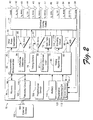
- Fig. 2 is a functional block diagram of a multi-chamber implantable stimulation device illustrating exemplary basic elements of a stimulation device which can provide cardioversion, defibrillation and/or pacing stimulation in up to four chambers of the heart.
- Fig. 3 is a flow diagram that describes steps in a method in accordance with one embodiment.
- Fig. 4 is a graph that is useful in understanding various inventive embodiments.
- Fig. 5 illustrates a three dimensional surface that can be constructed in accordance with one or more described embodiments.
- Fig. 6 is a flow diagram that describes steps in a method in accordance with one embodiment.
- Fig. 7 is a graph that is useful in understanding various inventive embodiments.
- A-V timing the timing between the atria and the ventricles
- V-V timing the timing between the right ventricle and the left ventricle
- the hemodynamic performance of a CHF patient is monitored by an implanted stimulation device. This can be done by monitoring the patient's cardiac output.
- a patient's cardiac output can be monitored using any number of known sensors. Such sensors can allow such things as stroke volume and other parameters associated with a patient's cardiac output to be monitored..
- Multiple different variables associated with the patient are monitored and timing parameters associated with A-V and/or V-V timing (i.e. those timing parameters that optimize the patient's hemodynamic performance) are ascertained in an attempt to optimize the patient's hemodynamic performance for a given set of variables.
- the monitored variables are independent of the patient's heart function.
- the timing parameters are stored in the stimulation device and, if a patient is determined to subsequently satisfy a given set of variables for which timing parameters exist, the timing parameters are used to pace the patient. If, for a given set of variables, timing parameters do not exist, then the stimulation device is programmed to automatically determine optimal timing parameters and store those parameters in memory for future use. Over time, a patient profile is developed and used to pace the patient in a manner that optimizes their hemodynamic performance for a given set of variables.
- the term “optimize” is used to describe a patient's hemodynamic performance as provided by one or more "optimized” timing parameters that are used to pace the patient.
- the term “optimize” is used in a relative sense to include, not only factually optimal hemodynamic performance, but improved hemodynamic performance that is improved over hemodynamic performance that would otherwise exist in the absence of the inventive techniques described herein.
- Fig. 1 illustrates a stimulation device 10 in electrical communication with a patient's heart 12 suitable for delivering multi-chamber stimulation and shock therapy.
- the portions of the heart 10 illustrated include the right ventricle 14, the right atrium 15, the left ventricle 17, and the left atrium 18.
- the left-side of the heart is meant to denote the portions of the heart encompassing the left ventricle 17 and the left atrium 18 and those portions of the coronary sinus, great cardiac vein, and its associated tributaries, which are adjacent the left atrium and left ventricle.
- the stimulation device 10 is coupled to an implantable right atrial lead 20 having at least an atrial tip electrode 22, and preferably a right atrial ring electrode 23, which typically is implanted in the patient's right atrial appendage.
- the stimulation device 10 is coupled to a "coronary sinus" lead 24 designed for placement in the "coronary sinus region" via the coronary sinus os so as to place one or more distal electrodes adjacent to the left ventricle 17 and one or more proximal electrodes adjacent to the left atrium 18.
- coronary sinus region refers to the vasculature of the left ventricle, including any portion of the coronary sinus, great cardiac vein, left marginal vein, left posterior ventricular vein, middle cardiac vein, and/or small cardiac vein or any other cardiac vein accessible by the coronary sinus.
- the coronary sinus lead 24 is designed to receive atrial and ventricular cardiac signals and to deliver: left ventricular pacing therapy using, for example, a left ventricular tip electrode 25 and a left ventricular ring electrode 26; left atrial pacing therapy using, for example, a first and second left atrial ring electrode, 27 and 28; and shocking therapy using at least a left atrial coil electrode 29.
- the stimulation device 10 is also shown in electrical communication with the patient's heart 12 by way of an implantable right ventricular lead 30 having a right ventricular tip electrode 32, a right ventricular ring electrode 34, a right ventricular (RV) coil electrode 36, and an SVC coil electrode 38.
- the right ventricular lead 30 is transvenously inserted into the heart 12 so as to place the right ventricular tip electrode 32 in the right ventricular apex so that the RV coil electrode 36 will be positioned in the right ventricle and the SVC coil electrode 38 will be positioned in the superior vena cava.
- the right ventricular lead 30 is capable of receiving cardiac signals, and delivering stimulation in the form of pacing and shock therapy to the right ventricle 14.
- Fig. 2 illustrates a simplified block diagram of the multi-chamber implantable stimulation device 10, which is capable of treating both fast and slow arrhythmias with stimulation therapy, including cardioversion, defibrillation, and pacing stimulation. While a particular multi-chamber device is shown, this is for illustration purposes only, and one of skill in the art could readily duplicate, eliminate or disable the appropriate circuitry in any desired combination to provide a device capable of treating the appropriate chamber(s) with cardioversion, defibrillation and/or pacing stimulation.
- various processing steps about to be described can be implemented in the form of software instructions that are resident on a computer-readable media that is located on the stimulation device. Accordingly, aspects of the invention described herein extend to all forms of computer-readable media, whether on the stimulation device (or monitoring device) or not, when such media contains instructions that, when executed by one or more processors, implement the methods described herein.
- the stimulation device 10 includes a housing 40 which is often referred to as "can”, “case” or “case electrode”, and which may be programmably selected to act as the return electrode for all "unipolar" modes.
- the housing 40 may further be used as a return electrode alone or in combination with one or more of the coil electrodes 29, 36, or 38, for shocking purposes.
- the housing 40 further includes a connector (not shown) having a plurality of terminals, 42, 43, 44, 45, 46, 47, 48, 52, 54, 56, and 58 (shown schematically and, for convenience, the names of the electrodes to which they are connected are shown next to the terminals). While it is recognized that current devices are limited to the number of terminals due to International Standards, one of skill in the art could readily eliminate some of the terminals/electrodes to fit in the existing device configurations and permit programmability to select which terminals connect to which electrodes. However, in the near future, the standards may change to permit multi-polar in-line connectors, and multiple feedthroughs connectors could readily be manufactured to accommodate the configuration shown in Fig. 2.
- the connector includes at least a right atrial tip terminal 42 and a right atrial ring terminal 43, adapted for connection to the atrial tip electrode and ring electrodes 22 and 23, respectively.
- the connector includes at least a left ventricular tip terminal 44, a left ventricular ring electrode 45, a first left atrial ring terminal 46, a second left atrial ring terminal 47, and a left atrial shocking terminal 48, which are adapted for connection to the left ventricular tip electrode 25, left ventricular ring 26, the first left atrial tip electrode 27, the second left atrial ring electrode 28, and the left atrial coil electrode 29, respectively.
- the connector further includes a right ventricular tip terminal 52, a right ventricular ring terminal 54, a right ventricular (RV) shocking terminal 56, and an SVC shocking terminal 58, which are adapted for connection to the right ventricular tip electrode 32, right ventricular ring electrode 34, the RV coil electrode 36, and the SVC coil electrode 38, respectively.
- RV right ventricular
- SVC shocking terminal 58 an SVC shocking terminal 58, which are adapted for connection to the right ventricular tip electrode 32, right ventricular ring electrode 34, the RV coil electrode 36, and the SVC coil electrode 38, respectively.
- the microcontroller 60 typically includes a microprocessor, or equivalent control circuitry, designed specifically for controlling the delivery of stimulation therapy, and may further include RAM or ROM memory, logic and timing circuitry, state machine circuitry, and I/O circuitry.
- the microcontroller 60 includes the ability to process or monitor input signals (data) as controlled by a program code stored in a designated block of memory.
- the details of the design and operation of the microcontroller 60 are not critical to the present invention. Rather, any suitable microcontroller 60 may be used that carries out the functions described herein.
- the use of microprocessor-based control circuits for performing timing and data analysis functions are well known in the art.
- an atrial pulse generator 70 and a ventricular pulse generator 72 generate pacing stimulation pulses for delivery by the right atrial lead 20, the right ventricular lead 30, and/or the coronary sinus lead 24 via a switch bank 74. It is understood that in order to provide stimulation therapy in each of the four chambers of the heart, the atrial pulse generator 70 and the ventricular pulse generator 72 may include dedicated, independent pulse generators, multiplexed pulse generators, or shared pulse generators. The atrial pulse generator 70 and the ventricular pulse generator 72 are controlled by the microcontroller 60 via appropriate control signals 76 and 78, respectively, to trigger or inhibit the stimulation pulses.
- the microcontroller 60 further includes timing control circuitry 79 which is used to control the timing of such stimulation pulses (e.g., pacing rate, atrio-ventricular (AV) delay, atrial interconduction (A-A) delay, or ventricular interconduction (V-V) delay, etc.), as well as to keep track of the timing of refractory periods, PVARP intervals, noise detection windows, evoked response windows, alert intervals, marker channel timing (via marker channel logic 81), etc., which is well known in the art.
- timing control circuitry 79 which is used to control the timing of such stimulation pulses (e.g., pacing rate, atrio-ventricular (AV) delay, atrial interconduction (A-A) delay, or ventricular interconduction (V-V) delay, etc.), as well as to keep track of the timing of refractory periods, PVARP intervals, noise detection windows, evoked response windows, alert intervals, marker channel timing (via marker channel logic 81), etc., which
- the microcontroller can be programmed with one or timing algorithms 83.
- the timing algorithm(s) can operate to enable various timing parameters to be adjusted to determine optimal hemodynamic performance of a patient with congestive heart failure (CHF).
- CHF congestive heart failure
- the switch bank 74 includes a plurality of switches for connecting the desired electrodes to the appropriate I/O circuits, thereby providing complete electrode programmability. Accordingly, the switch bank 74, in response to a control signal 80 from the microcontroller 60, determines the polarity of the stimulation pulses (e.g. unipolar, bipolar, combipolar, etc.) and various shocking vectors by selectively closing the appropriate combination of switches (not shown) as is known in the art.
- polarity of the stimulation pulses e.g. unipolar, bipolar, combipolar, etc.
- Atrial sensing circuits 82 and ventricular sensing circuits 84 may also be selectively coupled to the right atrial lead 20, coronary sinus lead 24, and the right ventricular lead 30, through the switch bank 74, for detecting the presence of cardiac activity in each of the four chambers of the heart. Accordingly, the atrial and ventricular sensing circuits 82 and 84 may include dedicated sense amplifiers, multiplexed amplifiers, or shared amplifiers.
- the switch bank 74 determines the "sensing polarity" of the cardiac signal by selectively closing the appropriate switches. In this way, the clinician may program the sensing polarity independent of the stimulation polarity.
- the atrial sensing circuit 82 or the ventricular sensing circuit 84 preferably employ one or more low power, precision amplifiers with programmable gain and/or automatic gain control, bandpass filtering, and a threshold detection circuit, to selectively sense the cardiac signal of interest.
- the automatic gain control enables the stimulation device 10 to deal effectively with the difficult problem of sensing the low amplitude signal characteristics of atrial or ventricular fibrillation.
- the outputs of the atrial and ventricular sensing circuits, 82 and 84 are connected to the microcontroller 60 for triggering or inhibiting the atrial and ventricular pulse generators, 70 and 72, respectively, in a demand fashion, in response to the absence or presence of cardiac activity, respectively, in the appropriate chambers of the heart.
- the stimulation device 10 utilizes the atrial and ventricular sensing circuits, 82 and 84, to sense cardiac signals for determining whether a rhythm is physiologic or pathologic.
- sensing is reserved for the noting of an electrical signal
- detection is the processing of these sensed signals and noting the presence of an arrhythmia.
- the timing intervals between sensed events e.g. P-waves, R-waves, and depolarization signals associated with fibrillation which are sometimes referred to as "F-waves" or "Fib-waves
- F-waves depolarization signals associated with fibrillation which are sometimes referred to as "F-waves" or "Fib-waves
- a predefined rate zone limit e.g.
- bradycardia normal, low rate VT, high rate VT, and fibrillation rate zones
- various other characteristics e.g. sudden onset, stability, physiologic sensors, and morphology, etc.
- bradycardia pacing antitachycardia pacing
- cardioversion shocks or defibrillation shocks collectively referred to as "tiered therapy”
- Cardiac signals are also applied to the inputs of an analog-to-digital (A/D) data acquisition system 90.
- the data acquisition system 90 is configured to acquire intracardiac electrogram signals, convert the raw analog data into digital signals, and store the digital signals for later processing and/or telemetric transmission to an external device 102.
- the data acquisition system 90 is coupled to the right atrial lead 20, the coronary sinus lead 24, and the right ventricular lead 30 through the switch bank 74 to sample cardiac signals across any pair of desired electrodes.
- the microcontroller 60 is further coupled to a memory 94 by a suitable data/address bus 96, wherein the programmable operating parameters used by the microcontroller 60 are stored and modified, as required, in order to customize the operation of the stimulation device 10 to suit the needs of a particular patient.
- Such operating parameters define, for example, pacing pulse amplitude, pulse duration, electrode polarity, rate, sensitivity, automatic features, arrhythmia detection criteria, and the amplitude, waveshape and vector of each shocking pulse to be delivered to the patient's heart 12 within each respective tier of therapy.
- the operating parameters of the stimulation device 10 may be non-invasively programmed into the memory 94 through a telemetry circuit 100 in telemetric communication with the external device 102, such as a programmer, transtelephonic transceiver, or a diagnostic system analyzer.
- the telemetry circuit 100 is activated by the microcontroller 60 by a control signal 106.
- the telemetry circuit 100 advantageously allows intracardiac electrograms and status information relating to the operation of the stimulation device 10 (as contained in the microcontroller 60 or memory 94) to be sent to the external device 102 through the established communication link 104.
- the stimulation device 10 can further include one or more physiologic sensors 108.
- physiologic sensors are referred to as a "rate-responsive" sensors because they are typically used to adjust pacing stimulation rate according to the exercise state of the patient.
- physiological sensors 108 may further be used to detect changes in cardiac output, changes in the physiological condition of the heart, patient activity, or diurnal changes in activity (e.g. detecting sleep and wake states).
- a physiological parameter of the heart which may be measured to optimize such pacing and to indicate when such pacing may be inhibited or terminated is the stroke volume of the heart.
- the microcontroller 60 responds by adjusting the various pacing parameters (such as rate, AV Delay, A-A Delay, V-V Delay, etc.) at which the atrial and ventricular pulse generators, 70 and 72, generate stimulation pulses.
- pacing parameters such as rate, AV Delay, A-A Delay, V-V Delay, etc.
- a common type of rate responsive sensor is an activity sensor, such as an accelerometer or a piezoelectric crystal, which is mounted within the housing 40 of the stimulation device 10.
- Other types of physiologic sensors are also known, for example, sensors which sense the oxygen content of blood, respiration rate and/or minute ventilation, pH of blood, ventricular gradient, etc.
- the stimulation device 10 additionally includes a power source such as a battery 110 that provides operating power to all the circuits shown in Fig. 2.
- a power source such as a battery 110 that provides operating power to all the circuits shown in Fig. 2.
- the battery 110 is capable of operating at low current drains for long periods of time, and also be capable of providing high-current pulses (for capacitor charging) when the patient requires a shock pulse.
- the battery 110 preferably has a predictable discharge characteristic so that elective replacement time can be detected. Accordingly, the stimulation device 10 can employ lithium/silver vanadium oxide batteries.
- the stimulation device 10 can be a primary function of the stimulation device 10 to operate as an implantable cardioverter/defibrillator (ICD) device. That is, it can detect the occurrence of an arrhythmia, and automatically apply an appropriate electrical shock therapy to the heart aimed at terminating the detected arrhythmia.
- the microcontroller 60 further controls a shocking circuit 116 by way of a control signal 118.
- the shocking circuit 116 generates shocking pulses of low (up to 0.5 joules), moderate (0.5 - 10 joules), or high (11 to 40 joules) energy, as controlled by the microcontroller 60.
- Such shocking pulses are applied to the patient's heart through at least two shocking electrodes, and as shown in this embodiment, selected from the left atrial coil electrode 29, the RV coil electrode 36, and/or the SVC coil electrode 38 (Fig. 1).
- the housing 40 may act as an active electrode in combination with the RV electrode 36, or as part of a split electrical vector using the SVC coil electrode 38 or the left atrial coil electrode 29 (i.e., using the RV electrode as the common electrode).
- Cardioversion shocks are generally considered to be of low to moderate energy level (so as to minimize pain felt by the patient), and/or synchronized with an R-wave and/or pertaining to the treatment of tachycardia.
- Defibrillation shocks are generally of moderate to high energy level (i.e., corresponding to thresholds in the range of 5-40 joules), delivered asynchronously (since R-waves may be too disorganized), and pertaining exclusively to the treatment of fibrillation.
- the microcontroller 60 is capable of controlling the synchronous or asynchronous delivery of the shocking pulses.
- the stimulation device 10 can have an impedance measuring circuit 120 including an impedance measuring current source 112 and a voltage measuring circuit 90 (shown in Fig. 2 as an A/D converter), which can be enabled by the microcontroller 60 by a control signal 114 for providing stroke volume measurements of the heart.
- the current source 112 can provide an alternating or pulsed excitation current.
- the voltage measuring circuitry 90 may also take the form of, for example, a differential amplifier.
- an impedance measuring circuit 120 includes, but are not limited to, lead impedance surveillance during the acute and chronic phases for proper lead positioning or dislodgment; detecting operable electrodes and automatically switching to an operable pair if dislodgment occurs; measuring a respiration parameter (for example, tidal volume, respiration rate, minute ventilation or volume, abnormal or periodic breathing); measuring thoracic impedance for determining shock thresholds and shock timing (corresponding to the diastolic time); detecting when the device has been implanted; measuring a cardiac parameter (such as, stroke volume, wall thickness, left ventricular volume, etc.); and detecting the opening of the valves, etc.
- a respiration parameter for example, tidal volume, respiration rate, minute ventilation or volume, abnormal or periodic breathing
- thoracic impedance for determining shock thresholds and shock timing (corresponding to the diastolic time)
- detecting when the device has been implanted measuring a cardiac parameter (such as, stroke volume, wall thickness, left
- the impedance measuring circuit is used to monitor left heart disease and provides appropriate stimulation therapy, such as altering rate, AV , A-A , or V-V delays.
- the impedance measuring circuit 120 can be advantageously coupled to the switch bank 74 so that any desired electrode can be used. Impedance may also be useful in verifying hemodynamic collapse to confirm that ATP has failed and/or VF has begun.
- the microcontroller 60 is coupled to the voltage measuring circuit 90 and the current source 112 for receiving a magnitude of the established current and a magnitude of the monitored voltage.
- the microcontroller 60 operating under program instructions, divides the magnitude of the monitored or measured voltage by the magnitude of the established current to determine an impedance value. Once the impedance signals are determined, they may be delivered to the memory 94 for storage and later retrieved by the microcontroller 60 for therapy adjustment or telemetry transmission.
- the telemetry circuitry receives the impedance values from the microcontroller 60 and transmits them to the external programmer. The impedance value may then be monitored by the patient's physician to enable the physician to track the patient's condition.
- the impedance measuring circuit 120 is advantageously coupled to the switch bank 74 so that any desired electrode may be used.
- the current source 112 may be programmably configured between a desired pair of electrodes, and the voltage measuring circuit 90 may be programmably configured between the same or preferably a different pair of electrodes.
- Fig. 3 is a flow diagram that describes steps in a method in accordance with one embodiment.
- the method can be implemented in any suitable hardware, software, firmware or combination thereof.
- the method can be implemented by a suitably programmed stimulation device.
- Step 300 determines values of multiple variables associated with a CHF patient.
- Exemplary variables can include, without limitation, the time of day, patient's posture, and activity level of the patient.
- the values of these variables can be determined using known sensors or components that comprise part of the stimulation device.
- the time of day can be determined by an internal clock.
- the patient's posture can be determined using known techniques and sensors.
- one or more accelerometers can be used to determine the patient's posture.
- the activity level of the patient can be determined using known activity sensors.
- Step 300 thus provides a set of variable values.
- Step 302 determines, for a given variable set, whether optimized timing parameters exist.
- the optimized timing parameters can comprise those associated with one or both of A-V and V-V timing.
- the stimulation device can implement this step by checking in memory to determine whether, for a given set of variables, there exists optimized timing parameters. If optimized timing parameters exist for a given set of variables, then step 304 paces the patient using the optimized timing parameters. Step 306 then determines whether any of the variable values change. If not, then the method loops back to step 304 and continues pacing the patient using the timing parameters associated with the given variable set. If, on the other hand, the variable values change, then the method loops back to step 300 and determines the values of the variables.
- the variables can have ranges that define tolerances within which they can be considered as unchanged.
- step 308 automatically determines optimized timing parameters for the variable set. This step can be implemented in any suitable way, examples of which are given below in the section entitled "Determining Optimized Timing Parameters”. Step 310 then saves the timing parameters in memory for a given variable set and step 304 paces the patient using the optimized timing parameters.
- this method can build a patient profile so that for a given set of variables, optimized timing parameters can be selected and automatically used to pace the patient so that the patient's hemodynamic performance is optimized.
- Fig. 4 shows an exemplary optimal V-V timing profile for a particular patient.
- Profile A shows a curve that describes the optimal timing for the patient in a supine position through the day.
- Profile B shows a curve that describes the optimal timing for the patient in an upright position but resting (while, for example, sitting in a chair).
- Profile C shows a curve that describes the optimal timing for the patient in an upright position while exercising at a maximum exercise rate.
- the optimal V-V timing varies as a function of the time of day, patient posture and activity level.
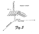
- Fig. 5 shows but one example of how the optimal timing parameters for the upright position can be expressed generally at 500.
- a three dimensional plot defines a surface that represents the optimal V-V timing in milliseconds as a function of the time of day and activity level.
- the stimulation device need only ascertain the time of day and activity level of the patient in order to select the appropriate timing parameters for pacing the patient for V-V timing.
- the stimulation device ascertains that the patient is in the upright position.
- the time of day is determined to be 8:00 A.M and the level of activity is low.
- a point on surface 500 can be found for the corresponding time and activity level (i.e.
- This point corresponds to a V-V timing parameter that can then be used to pace the patient. It is to be appreciated that a similar surface can be defined for A-V timing. Additionally, other surfaces can be defined for other patient postures so that for any combination of postures, times of day and activity levels, the appropriate timing parameters for pacing a patient can be ascertained.
- Fig. 6 is a flow diagram that describes steps in a method in accordance with one embodiment.
- the method can be implemented in any suitable hardware, software, firmware or combination thereof.
- the method can be implemented by a suitably programmed stimulation device.
- the method about to be described embellishes step 308 in Fig. 3 above.
- Step 600 monitors the patient's hemodynamic performance. Monitoring of the hemodynamic performance can take place using any suitable metrics that can be used to monitor hemodynamic performance.
- Step 602 establishes timing parameters for pacing a CHF patient. This step can be implemented in any suitable manner. For example, the step can be implemented using preprogrammed parameters or by using a set of base line parameters.
- Step 604 paces the patient using the established timing parameters.
- Step 606 evaluates the patient's hemodynamic performance in light of the timing parameters and step 608 manipulates the timing parameters. Manipulation of the timing parameters can take place using any suitable manipulation techniques. Specific examples are given below in the section entitled "Manipulation of Timing Parameters".
- Step 608 desirably loops back to step 606 and continues to evaluate and manipulate the timing parameters for purposes of hemodynamic evaluation. Looping back between steps 608 and 606 can take place any desirable number of times.
- Step 610 selects the timing parameters that optimize the patient's hemodynamic performance. For example, as steps 608 and 606 loop back and forth, hemodynamic performance data can be recorded by the stimulation device. After a number of evaluations have taken place, step 610 can select the timing parameters that are associated with the best hemodynamic performance for that patient. Thus, the method selects the timing parameters that optimize the patient's hemodynamic performance given the universe of acquired hemodynamic performance data.
- Timing parameters in order to ascertain the timing parameters that optimize the patient's hemodynamic parameters can take place in a number of different ways.
- manipulation of the timing parameters can take place through a dithering process in which the timing parameters are manipulated, perhaps randomly, in a trial and error way.
- a dithering process in which the timing parameters are manipulated, perhaps randomly, in a trial and error way.
- a graph 700 has three axes - a cardiac output axis expressing cardiac output in liters/minute, an A-V timing axis and a V-V timing axis, both of which are expressed in milliseconds.
- time of day 8-9 A.M.
- posture upright
- activity level low.
- the A-V timing is established at 200 ms
- the V-V timing is established at 0 ms, thus corresponding to point B. This means that there is a 200 ms difference in the A-V timing and a 0 ms difference in the V-V timing.
- the cardiac output is ascertained to be equal to 2.5 liters/minute as indicated.
- the cardiac output is determined to be about 3.0 liters/minute. Since this is more than the previous cardiac output, the associated timing parameters would be a better choice.
- the timing parameters are manipulated to provide 180 ms A-V timing and 0 ms V-V timing, thus corresponding with point C. At these timing parameters, the cardiac output is observed to be equal to 2.0 liters/minute. Since this cardiac output is less than the cardiac output associated with point A, selection of the parameters associated with point C would not be optimal.
- an optimization method known as the "steepest descent” method can be used.
- Steepest descent techniques are known and will be appreciated by those of skill in the art.
- U.S. Patent No. 5,987,328 discusses, generally, steepest descent techniques.
- other optimization techniques can be utilized and include, without limitation, the so-called "simplex" method.
- Simplex techniques are known and are not described in detail here. Additional material on the simplex method of optimization can be found in U.S. Patent Nos. 5,732,193 and 5,677,857.
Abstract
Description
- The present invention generally relates to implantable stimulation devices and methods and systems for treating patients with congestive heart failure (CHF).
- Congestive heart failure (CHF) is defined generally as the inability of the heart to deliver enough blood to the peripheral tissues to meet metabolic demands. Frequently, CHF is manifested by left heart dysfunction, but it can have a variety of sources. For example, CHF patients may have any one of several different conduction defects. The natural electrical activation system through the heart involves sequential events starting with the sino-atrial (SA) node, and continuing through the atrial conduction pathways of Bachmann's bundle and internodal tracts at the atrial level, followed by the atrio-ventricular (AV) node, Common Bundle of His, right and left bundle branches, and final distribution to the distal myocardial terminals via the Purkinje fiber network. A common type of intra-atrial conduction defect is known as intra-atrial block -- a condition where the atrial activation is delayed in getting from the right atrium to the left atrium. In left bundle branch block and right bundle branch block, the activation signals are not conducted in a normal fashion along the right or left bundle branches respectively. Thus, in a patient with bundle branch block, the activation of the ventricle is slowed, and the QRS is seen to widen due to the increased time for the activation to traverse the conduction path.
- CHF manifested by such conduction defects and/or other cardiomyopathies are the object of considerable research into treatments for improving cardiac output. In a healthy heart, cardiac output is typically not a problem. In patients with CHF, cardiac output is typically a problem. Because an unhealthy heart does not function properly insofar as important timing issues are concerned (e.g. A-V timing and V-V timing), cardiac output can be adversely affected. Hence, there is a continuing need to address timing issues in CHF patients. More specifically, there is a continuing need to provide improved cardiac output for CHF patients.
- Accordingly, this invention arose out of concerns associated with providing improved methods and systems for determining desirable or optimal timing parameters for pacing CHF patients.
- According to the invention, there is provided a stimulation device comprising one or more processors, memory and computer-readable instructions in the memory which, when executed by the one or more processors, cause the processors to: monitor multiple different variables associated with a patient having congestive heart failure (CHF), the variables comprising time of day, patient activity level, and posture; for a given set of variable values, select one or more timing parameters that can be used to administer pacing therapy to the patient; and administer pacing therapy using the selected timing parameters.
- According to another aspect of the invention, there is provided one or more computer-readable media having instructions thereon which, when executed by an implantable stimulation device, cause a stimulation device to: monitor multiple different variables associated with a patient having congestive heart failure (CHF), the variables comprising time of day, patient activity level, and posture; for a given set of variable values, select one or more timing parameters that can be used to administer pacing therapy to the patient effective to optimise a patient's hemodynamic performance; and administer pacing therapy using the selected timing parameters.
- According to a still further aspect of the invention, there is provided an implantable stimulation device comprising one or more processors, memory and computer-readable instructions in the memory which, when executed by the one or more processors cause the processors to: define one or more surfaces that describe optimal timing parameters for pacing a patient with congestive heart failure (CHF), the surfaces being defined as a function of patient posture, time of day, and activity level; determine a patient's posture, the time of day, and the activity level of the patient; find a point on the one or more surfaces that correspond to the patient's posture, the time of day, and the activity level; and pace the patient using timing parameters that correspond to said point on the one or more surfaces.
- Preferably, the instructions referred to above cause the stimulation device (10) to store the determined timing parameters for future use. Preferably, the instructions cause the stimulation device (10) to automatically determine parameters associated with A-V timing and/or V-V timing. Preferably the variables comprise one or more of a time of day variable, a patient posture variable, and a patient activity level variable.
- The invention also extends to methods carried out using the above devices.
- Various embodiments provide techniques and systems that can ensure that patients with congestive heart failure receive pacing therapy that optimizes their hemodynamic performance in view of various variables that pertain to the patient. Exemplary variables can include, without limitation, the time of day, patient posture and activity level.
- The following description is of the best mode presently contemplated for practicing the invention. This description is not to be taken in a limiting sense but is made merely for the purpose of describing the general principles of the invention.
- Fig. 1 is a simplified diagram illustrating an implantable stimulation device in electrical communication with at least three leads implanted into a patient's heart for delivering multi-chamber stimulation and shock therapy.
- Fig. 2 is a functional block diagram of a multi-chamber implantable stimulation device illustrating exemplary basic elements of a stimulation device which can provide cardioversion, defibrillation and/or pacing stimulation in up to four chambers of the heart.
- Fig. 3 is a flow diagram that describes steps in a method in accordance with one embodiment.
- Fig. 4 is a graph that is useful in understanding various inventive embodiments.
- Fig. 5 illustrates a three dimensional surface that can be constructed in accordance with one or more described embodiments.
- Fig. 6 is a flow diagram that describes steps in a method in accordance with one embodiment.
- Fig. 7 is a graph that is useful in understanding various inventive embodiments.
- There are typically two important timing considerations that pertain to pacing a patient with congestive heart failure (CHF). The first is the timing between the atria and the ventricles (known as the "A-V timing"), and the second is the timing between the right ventricle and the left ventricle (known as the "V-V timing"). In a healthy heart, there is a fairly consistent relationship that defines the A-V timing and the V-V timing. When a patient has CHF, however, the heart muscle does not function properly and, hence, timing disparities can exist. This leads to problems associated with trying to find desirable or optimal A-V and V-V timing for purposes of pacing CHF patients.
- In the embodiments described below, the hemodynamic performance of a CHF patient is monitored by an implanted stimulation device. This can be done by monitoring the patient's cardiac output. A patient's cardiac output can be monitored using any number of known sensors. Such sensors can allow such things as stroke volume and other parameters associated with a patient's cardiac output to be monitored.. Multiple different variables associated with the patient are monitored and timing parameters associated with A-V and/or V-V timing (i.e. those timing parameters that optimize the patient's hemodynamic performance) are ascertained in an attempt to optimize the patient's hemodynamic performance for a given set of variables. In the described embodiments, the monitored variables are independent of the patient's heart function. The timing parameters are stored in the stimulation device and, if a patient is determined to subsequently satisfy a given set of variables for which timing parameters exist, the timing parameters are used to pace the patient. If, for a given set of variables, timing parameters do not exist, then the stimulation device is programmed to automatically determine optimal timing parameters and store those parameters in memory for future use. Over time, a patient profile is developed and used to pace the patient in a manner that optimizes their hemodynamic performance for a given set of variables. In this document the term "optimize" is used to describe a patient's hemodynamic performance as provided by one or more "optimized" timing parameters that are used to pace the patient. The term "optimize" is used in a relative sense to include, not only factually optimal hemodynamic performance, but improved hemodynamic performance that is improved over hemodynamic performance that would otherwise exist in the absence of the inventive techniques described herein.
- The following description sets forth but one exemplary stimulation device that is capable of being used in connection with the various embodiments that are described below. It is to be appreciated and understood that other stimulation devices, including those that are not necessarily implantable, can be used and that the description below is given, in its specific context, to assist the reader in understanding, with more clarity, the inventive embodiments described herein.
- Fig. 1 illustrates a
stimulation device 10 in electrical communication with a patient'sheart 12 suitable for delivering multi-chamber stimulation and shock therapy. The portions of theheart 10 illustrated include theright ventricle 14, theright atrium 15, theleft ventricle 17, and theleft atrium 18. As used herein, the left-side of the heart is meant to denote the portions of the heart encompassing theleft ventricle 17 and theleft atrium 18 and those portions of the coronary sinus, great cardiac vein, and its associated tributaries, which are adjacent the left atrium and left ventricle. - To sense atrial cardiac signals and to provide right atrial chamber stimulation therapy, the
stimulation device 10 is coupled to an implantable rightatrial lead 20 having at least anatrial tip electrode 22, and preferably a rightatrial ring electrode 23, which typically is implanted in the patient's right atrial appendage. - To sense left atrial and ventricular cardiac signals and to provide left-chamber pacing therapy, the
stimulation device 10 is coupled to a "coronary sinus"lead 24 designed for placement in the "coronary sinus region" via the coronary sinus os so as to place one or more distal electrodes adjacent to theleft ventricle 17 and one or more proximal electrodes adjacent to theleft atrium 18. As used herein, the phrase "coronary sinus region" refers to the vasculature of the left ventricle, including any portion of the coronary sinus, great cardiac vein, left marginal vein, left posterior ventricular vein, middle cardiac vein, and/or small cardiac vein or any other cardiac vein accessible by the coronary sinus. - Accordingly, the
coronary sinus lead 24 is designed to receive atrial and ventricular cardiac signals and to deliver: left ventricular pacing therapy using, for example, a leftventricular tip electrode 25 and a leftventricular ring electrode 26; left atrial pacing therapy using, for example, a first and second left atrial ring electrode, 27 and 28; and shocking therapy using at least a leftatrial coil electrode 29. - The
stimulation device 10 is also shown in electrical communication with the patient'sheart 12 by way of an implantable rightventricular lead 30 having a rightventricular tip electrode 32, a rightventricular ring electrode 34, a right ventricular (RV)coil electrode 36, and anSVC coil electrode 38. Typically, the rightventricular lead 30 is transvenously inserted into theheart 12 so as to place the rightventricular tip electrode 32 in the right ventricular apex so that theRV coil electrode 36 will be positioned in the right ventricle and theSVC coil electrode 38 will be positioned in the superior vena cava. Accordingly, the rightventricular lead 30 is capable of receiving cardiac signals, and delivering stimulation in the form of pacing and shock therapy to theright ventricle 14. - Fig. 2 illustrates a simplified block diagram of the multi-chamber
implantable stimulation device 10, which is capable of treating both fast and slow arrhythmias with stimulation therapy, including cardioversion, defibrillation, and pacing stimulation. While a particular multi-chamber device is shown, this is for illustration purposes only, and one of skill in the art could readily duplicate, eliminate or disable the appropriate circuitry in any desired combination to provide a device capable of treating the appropriate chamber(s) with cardioversion, defibrillation and/or pacing stimulation. In addition, it will be appreciated and understood that various processing steps about to be described can be implemented in the form of software instructions that are resident on a computer-readable media that is located on the stimulation device. Accordingly, aspects of the invention described herein extend to all forms of computer-readable media, whether on the stimulation device (or monitoring device) or not, when such media contains instructions that, when executed by one or more processors, implement the methods described herein. - The
stimulation device 10 includes ahousing 40 which is often referred to as "can", "case" or "case electrode", and which may be programmably selected to act as the return electrode for all "unipolar" modes. Thehousing 40 may further be used as a return electrode alone or in combination with one or more of thecoil electrodes - The
housing 40 further includes a connector (not shown) having a plurality of terminals, 42, 43, 44, 45, 46, 47, 48, 52, 54, 56, and 58 (shown schematically and, for convenience, the names of the electrodes to which they are connected are shown next to the terminals). While it is recognized that current devices are limited to the number of terminals due to International Standards, one of skill in the art could readily eliminate some of the terminals/electrodes to fit in the existing device configurations and permit programmability to select which terminals connect to which electrodes. However, in the near future, the standards may change to permit multi-polar in-line connectors, and multiple feedthroughs connectors could readily be manufactured to accommodate the configuration shown in Fig. 2. - As such, to achieve right atrial sensing and pacing, the connector includes at least a right
atrial tip terminal 42 and a rightatrial ring terminal 43, adapted for connection to the atrial tip electrode andring electrodes - To achieve left chamber sensing, pacing and/or shocking, the connector includes at least a left
ventricular tip terminal 44, a leftventricular ring electrode 45, a first leftatrial ring terminal 46, a second leftatrial ring terminal 47, and a left atrialshocking terminal 48, which are adapted for connection to the leftventricular tip electrode 25,left ventricular ring 26, the first leftatrial tip electrode 27, the second leftatrial ring electrode 28, and the leftatrial coil electrode 29, respectively. - To support right chamber sensing, pacing and/or shocking, the connector further includes a right
ventricular tip terminal 52, a rightventricular ring terminal 54, a right ventricular (RV)shocking terminal 56, and an SVCshocking terminal 58, which are adapted for connection to the rightventricular tip electrode 32, rightventricular ring electrode 34, theRV coil electrode 36, and theSVC coil electrode 38, respectively. - At the core of the
stimulation device 10 is a programmable microcontroller ormicroprocessor 60 that controls the various modes of stimulation therapy. As is well known in the art, themicrocontroller 60 typically includes a microprocessor, or equivalent control circuitry, designed specifically for controlling the delivery of stimulation therapy, and may further include RAM or ROM memory, logic and timing circuitry, state machine circuitry, and I/O circuitry. Typically, themicrocontroller 60 includes the ability to process or monitor input signals (data) as controlled by a program code stored in a designated block of memory. The details of the design and operation of themicrocontroller 60 are not critical to the present invention. Rather, anysuitable microcontroller 60 may be used that carries out the functions described herein. The use of microprocessor-based control circuits for performing timing and data analysis functions are well known in the art. - As shown in Fig. 2, an
atrial pulse generator 70 and aventricular pulse generator 72 generate pacing stimulation pulses for delivery by the rightatrial lead 20, theright ventricular lead 30, and/or thecoronary sinus lead 24 via aswitch bank 74. It is understood that in order to provide stimulation therapy in each of the four chambers of the heart, theatrial pulse generator 70 and theventricular pulse generator 72 may include dedicated, independent pulse generators, multiplexed pulse generators, or shared pulse generators. Theatrial pulse generator 70 and theventricular pulse generator 72 are controlled by themicrocontroller 60 via appropriate control signals 76 and 78, respectively, to trigger or inhibit the stimulation pulses. - The
microcontroller 60 further includestiming control circuitry 79 which is used to control the timing of such stimulation pulses (e.g., pacing rate, atrio-ventricular (AV) delay, atrial interconduction (A-A) delay, or ventricular interconduction (V-V) delay, etc.), as well as to keep track of the timing of refractory periods, PVARP intervals, noise detection windows, evoked response windows, alert intervals, marker channel timing (via marker channel logic 81), etc., which is well known in the art. - In one embodiment, the microcontroller can be programmed with one or
timing algorithms 83. The timing algorithm(s) can operate to enable various timing parameters to be adjusted to determine optimal hemodynamic performance of a patient with congestive heart failure (CHF). - The
switch bank 74 includes a plurality of switches for connecting the desired electrodes to the appropriate I/O circuits, thereby providing complete electrode programmability. Accordingly, theswitch bank 74, in response to acontrol signal 80 from themicrocontroller 60, determines the polarity of the stimulation pulses (e.g. unipolar, bipolar, combipolar, etc.) and various shocking vectors by selectively closing the appropriate combination of switches (not shown) as is known in the art. -
Atrial sensing circuits 82 andventricular sensing circuits 84 may also be selectively coupled to the rightatrial lead 20,coronary sinus lead 24, and theright ventricular lead 30, through theswitch bank 74, for detecting the presence of cardiac activity in each of the four chambers of the heart. Accordingly, the atrial andventricular sensing circuits switch bank 74 determines the "sensing polarity" of the cardiac signal by selectively closing the appropriate switches. In this way, the clinician may program the sensing polarity independent of the stimulation polarity. - The
atrial sensing circuit 82 or theventricular sensing circuit 84 preferably employ one or more low power, precision amplifiers with programmable gain and/or automatic gain control, bandpass filtering, and a threshold detection circuit, to selectively sense the cardiac signal of interest. The automatic gain control enables thestimulation device 10 to deal effectively with the difficult problem of sensing the low amplitude signal characteristics of atrial or ventricular fibrillation. The outputs of the atrial and ventricular sensing circuits, 82 and 84, are connected to themicrocontroller 60 for triggering or inhibiting the atrial and ventricular pulse generators, 70 and 72, respectively, in a demand fashion, in response to the absence or presence of cardiac activity, respectively, in the appropriate chambers of the heart. - For arrhythmia detection, the
stimulation device 10 utilizes the atrial and ventricular sensing circuits, 82 and 84, to sense cardiac signals for determining whether a rhythm is physiologic or pathologic. As used herein "sensing" is reserved for the noting of an electrical signal, and "detection" is the processing of these sensed signals and noting the presence of an arrhythmia. The timing intervals between sensed events (e.g. P-waves, R-waves, and depolarization signals associated with fibrillation which are sometimes referred to as "F-waves" or "Fib-waves") are then classified by themicrocontroller 60 by comparing them to a predefined rate zone limit (e.g. bradycardia, normal, low rate VT, high rate VT, and fibrillation rate zones) and various other characteristics (e.g. sudden onset, stability, physiologic sensors, and morphology, etc.) in order to determine the type of remedial therapy that is needed (e.g. bradycardia pacing, antitachycardia pacing, cardioversion shocks or defibrillation shocks, collectively referred to as "tiered therapy"). - Cardiac signals are also applied to the inputs of an analog-to-digital (A/D)
data acquisition system 90. Thedata acquisition system 90 is configured to acquire intracardiac electrogram signals, convert the raw analog data into digital signals, and store the digital signals for later processing and/or telemetric transmission to anexternal device 102. Thedata acquisition system 90 is coupled to the rightatrial lead 20, thecoronary sinus lead 24, and theright ventricular lead 30 through theswitch bank 74 to sample cardiac signals across any pair of desired electrodes. - The
microcontroller 60 is further coupled to amemory 94 by a suitable data/address bus 96, wherein the programmable operating parameters used by themicrocontroller 60 are stored and modified, as required, in order to customize the operation of thestimulation device 10 to suit the needs of a particular patient. Such operating parameters define, for example, pacing pulse amplitude, pulse duration, electrode polarity, rate, sensitivity, automatic features, arrhythmia detection criteria, and the amplitude, waveshape and vector of each shocking pulse to be delivered to the patient'sheart 12 within each respective tier of therapy. - Advantageously, the operating parameters of the
stimulation device 10 may be non-invasively programmed into thememory 94 through atelemetry circuit 100 in telemetric communication with theexternal device 102, such as a programmer, transtelephonic transceiver, or a diagnostic system analyzer. Thetelemetry circuit 100 is activated by themicrocontroller 60 by acontrol signal 106. Thetelemetry circuit 100 advantageously allows intracardiac electrograms and status information relating to the operation of the stimulation device 10 (as contained in themicrocontroller 60 or memory 94) to be sent to theexternal device 102 through the establishedcommunication link 104. - The
stimulation device 10 can further include one or morephysiologic sensors 108. Some physiologic sensors are referred to as a "rate-responsive" sensors because they are typically used to adjust pacing stimulation rate according to the exercise state of the patient. However,physiological sensors 108 may further be used to detect changes in cardiac output, changes in the physiological condition of the heart, patient activity, or diurnal changes in activity (e.g. detecting sleep and wake states). A physiological parameter of the heart, which may be measured to optimize such pacing and to indicate when such pacing may be inhibited or terminated is the stroke volume of the heart. Accordingly, themicrocontroller 60 responds by adjusting the various pacing parameters (such as rate, AV Delay, A-A Delay, V-V Delay, etc.) at which the atrial and ventricular pulse generators, 70 and 72, generate stimulation pulses. A common type of rate responsive sensor is an activity sensor, such as an accelerometer or a piezoelectric crystal, which is mounted within thehousing 40 of thestimulation device 10. Other types of physiologic sensors are also known, for example, sensors which sense the oxygen content of blood, respiration rate and/or minute ventilation, pH of blood, ventricular gradient, etc. - The
stimulation device 10 additionally includes a power source such as abattery 110 that provides operating power to all the circuits shown in Fig. 2. For thestimulation device 10, which employs shocking therapy, thebattery 110 is capable of operating at low current drains for long periods of time, and also be capable of providing high-current pulses (for capacitor charging) when the patient requires a shock pulse. Thebattery 110 preferably has a predictable discharge characteristic so that elective replacement time can be detected. Accordingly, thestimulation device 10 can employ lithium/silver vanadium oxide batteries. - It can be a primary function of the
stimulation device 10 to operate as an implantable cardioverter/defibrillator (ICD) device. That is, it can detect the occurrence of an arrhythmia, and automatically apply an appropriate electrical shock therapy to the heart aimed at terminating the detected arrhythmia. To this end, themicrocontroller 60 further controls ashocking circuit 116 by way of acontrol signal 118. Theshocking circuit 116 generates shocking pulses of low (up to 0.5 joules), moderate (0.5 - 10 joules), or high (11 to 40 joules) energy, as controlled by themicrocontroller 60. Such shocking pulses are applied to the patient's heart through at least two shocking electrodes, and as shown in this embodiment, selected from the leftatrial coil electrode 29, theRV coil electrode 36, and/or the SVC coil electrode 38 (Fig. 1). As noted above, thehousing 40 may act as an active electrode in combination with theRV electrode 36, or as part of a split electrical vector using theSVC coil electrode 38 or the left atrial coil electrode 29 (i.e., using the RV electrode as the common electrode). - Cardioversion shocks are generally considered to be of low to moderate energy level (so as to minimize pain felt by the patient), and/or synchronized with an R-wave and/or pertaining to the treatment of tachycardia. Defibrillation shocks are generally of moderate to high energy level (i.e., corresponding to thresholds in the range of 5-40 joules), delivered asynchronously (since R-waves may be too disorganized), and pertaining exclusively to the treatment of fibrillation. Accordingly, the
microcontroller 60 is capable of controlling the synchronous or asynchronous delivery of the shocking pulses. - As further shown in Fig. 2, the
stimulation device 10 can have animpedance measuring circuit 120 including an impedance measuringcurrent source 112 and a voltage measuring circuit 90 (shown in Fig. 2 as an A/D converter), which can be enabled by themicrocontroller 60 by acontrol signal 114 for providing stroke volume measurements of the heart. Thecurrent source 112 can provide an alternating or pulsed excitation current. Thevoltage measuring circuitry 90 may also take the form of, for example, a differential amplifier. - The uses for an
impedance measuring circuit 120 include, but are not limited to, lead impedance surveillance during the acute and chronic phases for proper lead positioning or dislodgment; detecting operable electrodes and automatically switching to an operable pair if dislodgment occurs; measuring a respiration parameter (for example, tidal volume, respiration rate, minute ventilation or volume, abnormal or periodic breathing); measuring thoracic impedance for determining shock thresholds and shock timing (corresponding to the diastolic time); detecting when the device has been implanted; measuring a cardiac parameter (such as, stroke volume, wall thickness, left ventricular volume, etc.); and detecting the opening of the valves, etc. In the present embodiment, the impedance measuring circuit is used to monitor left heart disease and provides appropriate stimulation therapy, such as altering rate, AV , A-A , or V-V delays. Theimpedance measuring circuit 120 can be advantageously coupled to theswitch bank 74 so that any desired electrode can be used. Impedance may also be useful in verifying hemodynamic collapse to confirm that ATP has failed and/or VF has begun. - The
microcontroller 60 is coupled to thevoltage measuring circuit 90 and thecurrent source 112 for receiving a magnitude of the established current and a magnitude of the monitored voltage. Themicrocontroller 60, operating under program instructions, divides the magnitude of the monitored or measured voltage by the magnitude of the established current to determine an impedance value. Once the impedance signals are determined, they may be delivered to thememory 94 for storage and later retrieved by themicrocontroller 60 for therapy adjustment or telemetry transmission. The telemetry circuitry receives the impedance values from themicrocontroller 60 and transmits them to the external programmer. The impedance value may then be monitored by the patient's physician to enable the physician to track the patient's condition. - The
impedance measuring circuit 120 is advantageously coupled to theswitch bank 74 so that any desired electrode may be used. Thecurrent source 112 may be programmably configured between a desired pair of electrodes, and thevoltage measuring circuit 90 may be programmably configured between the same or preferably a different pair of electrodes. - Fig. 3 is a flow diagram that describes steps in a method in accordance with one embodiment. The method can be implemented in any suitable hardware, software, firmware or combination thereof. In one embodiment, the method can be implemented by a suitably programmed stimulation device.
- Step 300 determines values of multiple variables associated with a CHF patient. Exemplary variables can include, without limitation, the time of day, patient's posture, and activity level of the patient. The values of these variables can be determined using known sensors or components that comprise part of the stimulation device. For example, the time of day can be determined by an internal clock. The patient's posture can be determined using known techniques and sensors. For example, one or more accelerometers can be used to determine the patient's posture. The activity level of the patient can be determined using known activity sensors.
- Step 300 thus provides a set of variable values. Step 302 determines, for a given variable set, whether optimized timing parameters exist. The optimized timing parameters can comprise those associated with one or both of A-V and V-V timing. The stimulation device can implement this step by checking in memory to determine whether, for a given set of variables, there exists optimized timing parameters. If optimized timing parameters exist for a given set of variables, then step 304 paces the patient using the optimized timing parameters. Step 306 then determines whether any of the variable values change. If not, then the method loops back to step 304 and continues pacing the patient using the timing parameters associated with the given variable set. If, on the other hand, the variable values change, then the method loops back to step 300 and determines the values of the variables. It is to be appreciated and understood that the variables can have ranges that define tolerances within which they can be considered as unchanged.
- If
step 302 determines that optimized timing parameters do not exist for a given variable set, then step 308 automatically determines optimized timing parameters for the variable set. This step can be implemented in any suitable way, examples of which are given below in the section entitled "Determining Optimized Timing Parameters". Step 310 then saves the timing parameters in memory for a given variable set and step 304 paces the patient using the optimized timing parameters. - Over time, this method can build a patient profile so that for a given set of variables, optimized timing parameters can be selected and automatically used to pace the patient so that the patient's hemodynamic performance is optimized.
- Before discussing various ways in which optimized timing parameters can be determined, consider Fig. 4.
- Fig. 4 shows an exemplary optimal V-V timing profile for a particular patient. In this example, there are three different profiles designated "A", "B", and "C" as a function of the time of day. Profile A shows a curve that describes the optimal timing for the patient in a supine position through the day. Profile B shows a curve that describes the optimal timing for the patient in an upright position but resting (while, for example, sitting in a chair). Profile C shows a curve that describes the optimal timing for the patient in an upright position while exercising at a maximum exercise rate. Notice that the optimal V-V timing varies as a function of the time of day, patient posture and activity level. By recognizing that timing parameters (such as V-V timing and A-V timing) vary in accordance with these variables, various embodiments can take steps to ensure that a patient with congestive heart failure is paced at a level that is appropriate and optimal for them.
- Now, consider the situation in which one wishes to ascertain optimal timing parameters when the patient is in the upright position for all applicable activity levels and times of day. Over time, in accordance with the discussion pertaining to Fig. 3 above, a patient profile can be developed in which, for the possible combinations of times of day and activity levels when the patient is in the upright position, optimal timing parameters are ascertained.
- Fig. 5 shows but one example of how the optimal timing parameters for the upright position can be expressed generally at 500. In this example, a three dimensional plot defines a surface that represents the optimal V-V timing in milliseconds as a function of the time of day and activity level. Thus, when a person is determined to be in the upright position, the stimulation device need only ascertain the time of day and activity level of the patient in order to select the appropriate timing parameters for pacing the patient for V-V timing. Specifically, assume that the stimulation device ascertains that the patient is in the upright position. Assume further that the time of day is determined to be 8:00 A.M and the level of activity is low. As shown in Fig. 5, a point on
surface 500 can be found for the corresponding time and activity level (i.e. point A in the figure). This point corresponds to a V-V timing parameter that can then be used to pace the patient. It is to be appreciated that a similar surface can be defined for A-V timing. Additionally, other surfaces can be defined for other patient postures so that for any combination of postures, times of day and activity levels, the appropriate timing parameters for pacing a patient can be ascertained. - Fig. 6 is a flow diagram that describes steps in a method in accordance with one embodiment. The method can be implemented in any suitable hardware, software, firmware or combination thereof. In one embodiment, the method can be implemented by a suitably programmed stimulation device. The method about to be described embellishes
step 308 in Fig. 3 above. - Step 600 monitors the patient's hemodynamic performance. Monitoring of the hemodynamic performance can take place using any suitable metrics that can be used to monitor hemodynamic performance. Step 602 establishes timing parameters for pacing a CHF patient. This step can be implemented in any suitable manner. For example, the step can be implemented using preprogrammed parameters or by using a set of base line parameters. Step 604 paces the patient using the established timing parameters. Step 606 evaluates the patient's hemodynamic performance in light of the timing parameters and step 608 manipulates the timing parameters. Manipulation of the timing parameters can take place using any suitable manipulation techniques. Specific examples are given below in the section entitled "Manipulation of Timing Parameters". Step 608 desirably loops back to step 606 and continues to evaluate and manipulate the timing parameters for purposes of hemodynamic evaluation. Looping back between
steps - Step 610 then selects the timing parameters that optimize the patient's hemodynamic performance. For example, as
steps step 610 can select the timing parameters that are associated with the best hemodynamic performance for that patient. Thus, the method selects the timing parameters that optimize the patient's hemodynamic performance given the universe of acquired hemodynamic performance data. - Manipulation of the timing parameters in order to ascertain the timing parameters that optimize the patient's hemodynamic parameters can take place in a number of different ways.
- In one embodiment, manipulation of the timing parameters can take place through a dithering process in which the timing parameters are manipulated, perhaps randomly, in a trial and error way. As an example, consider Fig. 7.
- There, a
graph 700 has three axes - a cardiac output axis expressing cardiac output in liters/minute, an A-V timing axis and a V-V timing axis, both of which are expressed in milliseconds. The graph represents data that is taken for the following variable values: time of day = 8-9 A.M.; posture = upright; and activity level = low. Assume that the A-V timing is established at 200 ms, and the V-V timing is established at 0 ms, thus corresponding to point B. This means that there is a 200 ms difference in the A-V timing and a 0 ms difference in the V-V timing. At these points in this graph, the cardiac output is ascertained to be equal to 2.5 liters/minute as indicated. Now, assume that the A-V timing is maintained at the previous 200 ms and that the V-V timing is manipulated to equal 30 ms, with the left ventricle being stimulated first, thus corresponding to point A. When the patient's hemodynamic performance is evaluated in terms of their cardiac output, the cardiac output is determined to be about 3.0 liters/minute. Since this is more than the previous cardiac output, the associated timing parameters would be a better choice. Assume now that the timing parameters are manipulated to provide 180 ms A-V timing and 0 ms V-V timing, thus corresponding with point C. At these timing parameters, the cardiac output is observed to be equal to 2.0 liters/minute. Since this cardiac output is less than the cardiac output associated with point A, selection of the parameters associated with point C would not be optimal. - Hence, if these three data points (A, B, and C) were the only three data points for the given patient variables (i.e. time of day = 8-9 A.M; posture = upright; and activity level = low), then the parameters associated with point A would be selected and stored as the parameters that optimize hemodynamic performance for the given patient variables. This point is shown on surface 500 (Fig. 5) as the point that represents an optimized V-V timing.
- It should be noted, then, that the problem described above is essentially an optimization problem. Accordingly, and as a more preferred alternative to performing a trial and error manipulation of the timing parameters, a number of different optimization methods can be used and will be understood and appreciated by the skilled artisian.
- As but a few examples, an optimization method known as the "steepest descent" method can be used. Steepest descent techniques are known and will be appreciated by those of skill in the art. For example, U.S. Patent No. 5,987,328 discusses, generally, steepest descent techniques. Alternately, other optimization techniques can be utilized and include, without limitation, the so-called "simplex" method. Simplex techniques are known and are not described in detail here. Additional material on the simplex method of optimization can be found in U.S. Patent Nos. 5,732,193 and 5,677,857.
- In the embodiments described above, techniques and systems can ensure that patients with congestive heart failure receive pacing therapy that optimizes their hemodynamic performance in view of various variables that pertain to the patient. Exemplary variables described in this document include the time of day, patient posture and activity level. It is to be appreciated and understood that other variables could be utilized without departing from the spirit of the claimed subject matter.
Claims (9)
- A stimulation device (10) comprising one or more processors (60), memory (94) and computer-readable instructions in the memory (94) which, when executed by the one or more processors (60), cause the processors (60) to: monitor multiple different variables associated with a patient having congestive heart failure (CHF), the variables comprising time of day, patient activity level, and posture; for a given set of variable values, select one or more timing parameters that can be used to administer pacing therapy to the patient; and administer pacing therapy using the selected timing parameters.
- A device as claimed in Claim 2, characterised in that the instructions cause the one or more processors to select parameters associated with A-V timing and/or V-V timing.
- One or more computer-readable media having instructions thereon which, when executed by an implantable stimulation device, cause a stimulation device to: monitor multiple different variables associated with a patient having congestive heart failure (CHF), the variables comprising time of day, patient activity level, and posture; for a given set of variable values, select one or more timing parameters that can be used to administer pacing therapy to the patient effective to optimise a patient's hemodynamic performance; and administer pacing therapy using the selected timing parameters.
- Computer-readable media as claimed in Claim 3, characterised in that the instructions cause the stimulation device to select parameters associated with A-V timing and/or V-V timing.
- A stimulation device (10) comprising one or more processors (60), memory (94) and computer-readable instructions in the memory (94) which, when executed by the one or more processors (60), cause the processors (60) to: monitor multiple different variables associated with a patient having congestive heart failure (CHF), the variables being independent of the patient's heart function; for a given set of variables values, determine whether one or more timing parameters exist that can be used to administer pacing therapy to the patient to optimise the patient's hemodynamic performance; in an event that one or more timing parameters do exist for the given set of variable values, administer pacing therapy to the patient using the existing timing parameters; in an event that one or more timing parameters do not exist for the given set of variable values, automatically determine timing parameters that optimise the patient's hemodynamic performance for the given set of variables; and administer pacing therapy to the patient using the determined timing parameters.
- A device as claimed in Claim 5, characterised in that the instructions cause the stimulation device (10) to store the determined timing parameters for future use.
- A device as claimed in Claim 5 or Claim 6, characterised in that the instructions cause the stimulation device (10) to automatically determine parameters associated with A-V timing and/or V-V timing.
- A device as claimed in any of Claims 5 to 7, characterised in that the variables comprise one or more of a time of day variable, a patient posture variable, and a patient activity level variable.
- An implantable stimulation device (10) comprising one or more processors (60), memory (94) and computer-readable instructions in the memory (94) which, when executed by the one or more processors (60) cause the processors (60) to: define one or more surfaces that describe optimal timing parameters for pacing a patient with congestive heart failure (CHF), the surfaces being defined as a function of patient posture, time of day, and activity level; determine a patient's posture, the time of day, and the activity level of the patient; find a point on the one or more surfaces that correspond to the patient's posture, the time of day, and the activity level; and pace the patient using timing parameters that correspond to said point on the one or more surfaces.
Applications Claiming Priority (2)
| Application Number | Priority Date | Filing Date | Title |
|---|---|---|---|
| US09/999,408 US6751503B1 (en) | 2001-11-01 | 2001-11-01 | Methods and systems for treating patients with congestive heart failure (CHF) |
| US999408 | 2001-11-01 |
Publications (2)
| Publication Number | Publication Date |
|---|---|
| EP1308182A2 true EP1308182A2 (en) | 2003-05-07 |
| EP1308182A3 EP1308182A3 (en) | 2004-08-04 |
Family
ID=25546293
Family Applications (1)
| Application Number | Title | Priority Date | Filing Date |
|---|---|---|---|
| EP02257567A Ceased EP1308182A3 (en) | 2001-11-01 | 2002-10-31 | Implantable cardiac stimulation device |
Country Status (2)
| Country | Link |
|---|---|
| US (1) | US6751503B1 (en) |
| EP (1) | EP1308182A3 (en) |
Cited By (33)
| Publication number | Priority date | Publication date | Assignee | Title |
|---|---|---|---|---|
| WO2005089646A1 (en) * | 2004-03-16 | 2005-09-29 | Medtronic, Inc. | Sensitivity analysis for selecting therapy parameter sets |
| EP1627660A1 (en) * | 2004-08-20 | 2006-02-22 | Biotronik GmbH & Co. KG | Two lead three-chamber pacing system for CHF patients |
| WO2006079010A1 (en) * | 2005-01-21 | 2006-07-27 | Medtronic, Inc. | Implantable medical device with ventricular pacing protocol for sleep state |
| US7548783B1 (en) * | 2006-01-11 | 2009-06-16 | Pacesetter, Inc. | Implantable cardiac stimulation device having a system for providing atrial therapy based on circadian variations and method |
| US7717848B2 (en) | 2004-03-16 | 2010-05-18 | Medtronic, Inc. | Collecting sleep quality information via a medical device |
| US7775993B2 (en) | 2004-03-16 | 2010-08-17 | Medtronic, Inc. | Detecting sleep |
| US7792583B2 (en) | 2004-03-16 | 2010-09-07 | Medtronic, Inc. | Collecting posture information to evaluate therapy |
| US7805196B2 (en) | 2004-03-16 | 2010-09-28 | Medtronic, Inc. | Collecting activity information to evaluate therapy |
| WO2010126539A1 (en) * | 2009-04-30 | 2010-11-04 | Medtronic, Inc. | Medical device therapy based on posture and timing |
| US7881798B2 (en) | 2004-03-16 | 2011-02-01 | Medtronic Inc. | Controlling therapy based on sleep quality |
| US7908013B2 (en) | 2004-03-16 | 2011-03-15 | Medtronic, Inc. | Collecting activity information to evaluate therapy |
| US8016776B2 (en) | 2005-12-02 | 2011-09-13 | Medtronic, Inc. | Wearable ambulatory data recorder |
| US8021299B2 (en) | 2005-06-01 | 2011-09-20 | Medtronic, Inc. | Correlating a non-polysomnographic physiological parameter set with sleep states |
| US8055348B2 (en) | 2004-03-16 | 2011-11-08 | Medtronic, Inc. | Detecting sleep to evaluate therapy |
| US8135473B2 (en) | 2004-04-14 | 2012-03-13 | Medtronic, Inc. | Collecting posture and activity information to evaluate therapy |
| US8308661B2 (en) | 2004-03-16 | 2012-11-13 | Medtronic, Inc. | Collecting activity and sleep quality information via a medical device |
| US8335568B2 (en) | 2004-03-16 | 2012-12-18 | Medtronic, Inc. | Controlling therapy based on sleep quality |
| US8337431B2 (en) | 2004-03-16 | 2012-12-25 | Medtronic, Inc. | Collecting activity and sleep quality information via a medical device |
| US8725244B2 (en) | 2004-03-16 | 2014-05-13 | Medtronic, Inc. | Determination of sleep quality for neurological disorders |
| US8744587B2 (en) | 2006-03-24 | 2014-06-03 | Medtronic, Inc. | Collecting gait information for evaluation and control of therapy |
| US9050471B2 (en) | 2008-07-11 | 2015-06-09 | Medtronic, Inc. | Posture state display on medical device user interface |
| US9662045B2 (en) | 2008-07-11 | 2017-05-30 | Medtronic, Inc. | Generation of sleep quality information based on posture state data |
| US9737719B2 (en) | 2012-04-26 | 2017-08-22 | Medtronic, Inc. | Adjustment of therapy based on acceleration |
| US9776008B2 (en) | 2008-07-11 | 2017-10-03 | Medtronic, Inc. | Posture state responsive therapy delivery using dwell times |
| US9907959B2 (en) | 2012-04-12 | 2018-03-06 | Medtronic, Inc. | Velocity detection for posture-responsive therapy |
| US9919159B2 (en) | 2008-07-11 | 2018-03-20 | Medtronic, Inc. | Programming posture responsive therapy |
| US9956412B2 (en) | 2008-07-11 | 2018-05-01 | Medtronic, Inc. | Linking posture states for posture responsive therapy |
| US9956418B2 (en) | 2010-01-08 | 2018-05-01 | Medtronic, Inc. | Graphical manipulation of posture zones for posture-responsive therapy |
| US10071197B2 (en) | 2009-04-30 | 2018-09-11 | Medtronic, Inc. | Therapy system including multiple posture sensors |
| US10130815B2 (en) | 2003-09-15 | 2018-11-20 | Medtronic, Inc. | Automatic therapy adjustments |
| US10207118B2 (en) | 2008-07-11 | 2019-02-19 | Medtronic, Inc. | Associating therapy adjustments with posture states using a stability timer |
| US10471264B2 (en) | 2005-12-02 | 2019-11-12 | Medtronic, Inc. | Closed-loop therapy adjustment |
| US11596795B2 (en) | 2017-07-31 | 2023-03-07 | Medtronic, Inc. | Therapeutic electrical stimulation therapy for patient gait freeze |
Families Citing this family (32)
| Publication number | Priority date | Publication date | Assignee | Title |
|---|---|---|---|---|
| US7127289B2 (en) * | 2001-12-05 | 2006-10-24 | Cardiac Pacemakers, Inc. | Cardiac resynchronization system employing mechanical measurement of cardiac walls |
| US20040220636A1 (en) * | 2003-04-29 | 2004-11-04 | Medtronic, Inc. | Cardiac pacing therapy parameter programming |
| US20050125041A1 (en) * | 2003-11-05 | 2005-06-09 | Xiaoyi Min | Methods for ventricular pacing |
| US7627366B1 (en) | 2004-05-17 | 2009-12-01 | Pacesetter, Inc. | Analysis of polarization information |
| US7565195B1 (en) | 2005-04-11 | 2009-07-21 | Pacesetter, Inc. | Failsafe satellite pacemaker system |
| US7634313B1 (en) | 2005-04-11 | 2009-12-15 | Pacesetter, Inc. | Failsafe satellite pacemaker system |
| US7630763B2 (en) | 2005-04-20 | 2009-12-08 | Cardiac Pacemakers, Inc. | Thoracic or intracardiac impedance detection with automatic vector selection |
| US20060271121A1 (en) * | 2005-05-25 | 2006-11-30 | Cardiac Pacemakers, Inc. | Closed loop impedance-based cardiac resynchronization therapy systems, devices, and methods |
| US8494618B2 (en) * | 2005-08-22 | 2013-07-23 | Cardiac Pacemakers, Inc. | Intracardiac impedance and its applications |
| US9839781B2 (en) | 2005-08-22 | 2017-12-12 | Cardiac Pacemakers, Inc. | Intracardiac impedance and its applications |
| US7974691B2 (en) * | 2005-09-21 | 2011-07-05 | Cardiac Pacemakers, Inc. | Method and apparatus for controlling cardiac resynchronization therapy using cardiac impedance |
| US20070073352A1 (en) * | 2005-09-28 | 2007-03-29 | Euler David E | Method and apparatus for regulating a cardiac stimulation therapy |
| US8712519B1 (en) * | 2006-03-31 | 2014-04-29 | Pacesetter, Inc. | Closed-loop adaptive adjustment of pacing therapy based on cardiogenic impedance signals detected by an implantable medical device |
| US7751889B1 (en) * | 2007-04-11 | 2010-07-06 | Pacesetter, Inc. | Closed loop programming for individual adjustment of electro-mechanical synchrony |
| US20090076562A1 (en) * | 2007-09-17 | 2009-03-19 | Pacesetter, Inc. | System and method for adjusting av/pv delay |
| US7941217B1 (en) | 2008-03-25 | 2011-05-10 | Pacesetter, Inc. | Techniques for promoting biventricular synchrony and stimulation device efficiency using intentional fusion |
| US20090299423A1 (en) * | 2008-06-03 | 2009-12-03 | Pacesetter, Inc. | Systems and methods for determining inter-atrial conduction delays using multi-pole left ventricular pacing/sensing leads |
| US8249718B2 (en) | 2008-07-11 | 2012-08-21 | Medtronic, Inc. | Programming posture state-responsive therapy with nominal therapy parameters |
| US8886302B2 (en) * | 2008-07-11 | 2014-11-11 | Medtronic, Inc. | Adjustment of posture-responsive therapy |
| US8708934B2 (en) | 2008-07-11 | 2014-04-29 | Medtronic, Inc. | Reorientation of patient posture states for posture-responsive therapy |
| US8280517B2 (en) | 2008-09-19 | 2012-10-02 | Medtronic, Inc. | Automatic validation techniques for validating operation of medical devices |
| DE102009010487A1 (en) | 2008-11-21 | 2010-05-27 | Schaeffler Kg | Two-way clutch with axial disengagement |
| US8442634B2 (en) * | 2008-12-04 | 2013-05-14 | Pacesetter, Inc. | Systems and methods for controlling ventricular pacing in patients with long inter-atrial conduction delays |
| WO2010071488A1 (en) * | 2008-12-17 | 2010-06-24 | St. Jude Medical Ab | Implantable medical device and method for monitoring synchronicity of the ventricles of a heart |
| US8175720B2 (en) | 2009-04-30 | 2012-05-08 | Medtronic, Inc. | Posture-responsive therapy control based on patient input |
| US8388555B2 (en) | 2010-01-08 | 2013-03-05 | Medtronic, Inc. | Posture state classification for a medical device |
| US8579834B2 (en) | 2010-01-08 | 2013-11-12 | Medtronic, Inc. | Display of detected patient posture state |
| US9357949B2 (en) | 2010-01-08 | 2016-06-07 | Medtronic, Inc. | User interface that displays medical therapy and posture data |
| US9566441B2 (en) | 2010-04-30 | 2017-02-14 | Medtronic, Inc. | Detecting posture sensor signal shift or drift in medical devices |
| US8433419B2 (en) | 2010-10-13 | 2013-04-30 | Cardiac Pacemakers, Inc. | Method and apparatus for controlling neurostimulation according to physical state |
| EP2654884B1 (en) | 2010-12-20 | 2017-09-13 | Cardiac Pacemakers, Inc. | Physiologic response to posture |
| US9717915B2 (en) | 2013-03-13 | 2017-08-01 | Cardiac Pacemakers, Inc. | System and method for changing device parameters to control cardiac hemodynamics in a patient |
Citations (3)
| Publication number | Priority date | Publication date | Assignee | Title |
|---|---|---|---|---|
| US5677857A (en) | 1992-09-08 | 1997-10-14 | Toyota Jidosha Kabushiki Kaisha | Optimum design system and manufacturing method by use of the system |
| US5732193A (en) | 1909-01-26 | 1998-03-24 | Aberson; Michael | Method and apparatus for behavioristic-format coding of quantitative resource data/distributed automation protocol |
| US5987328A (en) | 1997-04-24 | 1999-11-16 | Ephremides; Anthony | Method and device for placement of transmitters in wireless networks |
Family Cites Families (12)
| Publication number | Priority date | Publication date | Assignee | Title |
|---|---|---|---|---|
| US5334222A (en) * | 1992-11-03 | 1994-08-02 | Cardiac Pacemakers, Inc. | Cardiac stimulating apparatus and method for heart failure therapy |
| US5554177A (en) * | 1995-03-27 | 1996-09-10 | Medtronic, Inc. | Method and apparatus to optimize pacing based on intensity of acoustic signal |
| US5725562A (en) * | 1995-03-30 | 1998-03-10 | Medtronic Inc | Rate responsive cardiac pacemaker and method for discriminating stair climbing from other activities |
| US5836987A (en) * | 1995-11-15 | 1998-11-17 | Cardiac Pacemakers, Inc. | Apparatus and method for optimizing cardiac performance by determining the optimal timing interval from an accelerometer signal |
| US5891176A (en) | 1996-05-09 | 1999-04-06 | Pacesetter, Inc. | System and method for providing hemodynamically optimal pacing |
| US5700283A (en) | 1996-11-25 | 1997-12-23 | Cardiac Pacemakers, Inc. | Method and apparatus for pacing patients with severe congestive heart failure |
| US5876353A (en) * | 1997-01-31 | 1999-03-02 | Medtronic, Inc. | Impedance monitor for discerning edema through evaluation of respiratory rate |
| US5800471A (en) | 1997-10-20 | 1998-09-01 | Cardiac Pacemakers, Inc. | Method for optimizing cardiac performance by determining the optimal pacing mode-AV delay from a transient heart rate signal for use in CHF, brady, and tachy/brady therapy devices |
| US6070100A (en) | 1997-12-15 | 2000-05-30 | Medtronic Inc. | Pacing system for optimizing cardiac output and determining heart condition |
| US6104949A (en) * | 1998-09-09 | 2000-08-15 | Vitatron Medical, B.V. | Medical device |
| US6259948B1 (en) * | 1998-11-13 | 2001-07-10 | Pacesetter, Inc. | Medical device |
| US6708061B2 (en) * | 2000-04-07 | 2004-03-16 | Cardiac Pacemakers, Inc. | Cardiac rhythm management system with optimization of cardiac performance using heart rate |
-
2001
- 2001-11-01 US US09/999,408 patent/US6751503B1/en not_active Expired - Lifetime
-
2002
- 2002-10-31 EP EP02257567A patent/EP1308182A3/en not_active Ceased
Patent Citations (3)
| Publication number | Priority date | Publication date | Assignee | Title |
|---|---|---|---|---|
| US5732193A (en) | 1909-01-26 | 1998-03-24 | Aberson; Michael | Method and apparatus for behavioristic-format coding of quantitative resource data/distributed automation protocol |
| US5677857A (en) | 1992-09-08 | 1997-10-14 | Toyota Jidosha Kabushiki Kaisha | Optimum design system and manufacturing method by use of the system |
| US5987328A (en) | 1997-04-24 | 1999-11-16 | Ephremides; Anthony | Method and device for placement of transmitters in wireless networks |
Cited By (52)
| Publication number | Priority date | Publication date | Assignee | Title |
|---|---|---|---|---|
| US10130815B2 (en) | 2003-09-15 | 2018-11-20 | Medtronic, Inc. | Automatic therapy adjustments |
| US8758242B2 (en) | 2004-03-16 | 2014-06-24 | Medtronic, Inc. | Collecting sleep quality information via a medical device |
| US7805196B2 (en) | 2004-03-16 | 2010-09-28 | Medtronic, Inc. | Collecting activity information to evaluate therapy |
| WO2005089646A1 (en) * | 2004-03-16 | 2005-09-29 | Medtronic, Inc. | Sensitivity analysis for selecting therapy parameter sets |
| US7717848B2 (en) | 2004-03-16 | 2010-05-18 | Medtronic, Inc. | Collecting sleep quality information via a medical device |
| US7775993B2 (en) | 2004-03-16 | 2010-08-17 | Medtronic, Inc. | Detecting sleep |
| US7792583B2 (en) | 2004-03-16 | 2010-09-07 | Medtronic, Inc. | Collecting posture information to evaluate therapy |
| US11096591B2 (en) | 2004-03-16 | 2021-08-24 | Medtronic, Inc. | Determination of sleep quality for neurological disorders |
| US10300283B2 (en) | 2004-03-16 | 2019-05-28 | Medtronic, Inc. | Determination of sleep quality for neurological disorders |
| US7881798B2 (en) | 2004-03-16 | 2011-02-01 | Medtronic Inc. | Controlling therapy based on sleep quality |
| US7908013B2 (en) | 2004-03-16 | 2011-03-15 | Medtronic, Inc. | Collecting activity information to evaluate therapy |
| US9623248B2 (en) | 2004-03-16 | 2017-04-18 | Medtronic, Inc. | Collecting sleep quality information via a medical device |
| US8792982B2 (en) | 2004-03-16 | 2014-07-29 | Medtronic, Inc. | Collecting posture information to evaluate therapy |
| US8032224B2 (en) | 2004-03-16 | 2011-10-04 | Medtronic, Inc. | Sensitivity analysis for selecting therapy parameter sets |
| US8055348B2 (en) | 2004-03-16 | 2011-11-08 | Medtronic, Inc. | Detecting sleep to evaluate therapy |
| US8335568B2 (en) | 2004-03-16 | 2012-12-18 | Medtronic, Inc. | Controlling therapy based on sleep quality |
| US8190253B2 (en) | 2004-03-16 | 2012-05-29 | Medtronic, Inc. | Collecting activity information to evaluate incontinence therapy |
| US8308661B2 (en) | 2004-03-16 | 2012-11-13 | Medtronic, Inc. | Collecting activity and sleep quality information via a medical device |
| US8332038B2 (en) | 2004-03-16 | 2012-12-11 | Medtronic, Inc. | Detecting sleep to evaluate therapy |
| US8725244B2 (en) | 2004-03-16 | 2014-05-13 | Medtronic, Inc. | Determination of sleep quality for neurological disorders |
| US8337431B2 (en) | 2004-03-16 | 2012-12-25 | Medtronic, Inc. | Collecting activity and sleep quality information via a medical device |
| US8396554B2 (en) | 2004-03-16 | 2013-03-12 | Medtronic, Inc. | Collecting posture information to evaluate therapy |
| US8447401B2 (en) | 2004-03-16 | 2013-05-21 | Medtronic, Inc. | Collecting posture information to evaluate therapy |
| US8688221B2 (en) | 2004-04-14 | 2014-04-01 | Medtronic, Inc. | Collecting posture and activity information to evaluate therapy |
| US8135473B2 (en) | 2004-04-14 | 2012-03-13 | Medtronic, Inc. | Collecting posture and activity information to evaluate therapy |
| EP1627660A1 (en) * | 2004-08-20 | 2006-02-22 | Biotronik GmbH & Co. KG | Two lead three-chamber pacing system for CHF patients |
| WO2006079010A1 (en) * | 2005-01-21 | 2006-07-27 | Medtronic, Inc. | Implantable medical device with ventricular pacing protocol for sleep state |
| US8021299B2 (en) | 2005-06-01 | 2011-09-20 | Medtronic, Inc. | Correlating a non-polysomnographic physiological parameter set with sleep states |
| US10471264B2 (en) | 2005-12-02 | 2019-11-12 | Medtronic, Inc. | Closed-loop therapy adjustment |
| US8444578B2 (en) | 2005-12-02 | 2013-05-21 | Medtronic, Inc. | Wearable ambulatory data recorder |
| US8016776B2 (en) | 2005-12-02 | 2011-09-13 | Medtronic, Inc. | Wearable ambulatory data recorder |
| US7548783B1 (en) * | 2006-01-11 | 2009-06-16 | Pacesetter, Inc. | Implantable cardiac stimulation device having a system for providing atrial therapy based on circadian variations and method |
| US9592379B2 (en) | 2006-03-24 | 2017-03-14 | Medtronic, Inc. | Collecting gait information for evaluation and control of therapy |
| US10251595B2 (en) | 2006-03-24 | 2019-04-09 | Medtronic, Inc. | Collecting gait information for evaluation and control of therapy |
| US8744587B2 (en) | 2006-03-24 | 2014-06-03 | Medtronic, Inc. | Collecting gait information for evaluation and control of therapy |
| US9050471B2 (en) | 2008-07-11 | 2015-06-09 | Medtronic, Inc. | Posture state display on medical device user interface |
| US10925517B2 (en) | 2008-07-11 | 2021-02-23 | Medtronic, Inc. | Posture state redefinition based on posture data |
| US9662045B2 (en) | 2008-07-11 | 2017-05-30 | Medtronic, Inc. | Generation of sleep quality information based on posture state data |
| US9919159B2 (en) | 2008-07-11 | 2018-03-20 | Medtronic, Inc. | Programming posture responsive therapy |
| US9968784B2 (en) | 2008-07-11 | 2018-05-15 | Medtronic, Inc. | Posture state redefinition based on posture data |
| US11672989B2 (en) | 2008-07-11 | 2023-06-13 | Medtronic, Inc. | Posture state responsive therapy delivery using dwell times |
| US9956412B2 (en) | 2008-07-11 | 2018-05-01 | Medtronic, Inc. | Linking posture states for posture responsive therapy |
| US10207118B2 (en) | 2008-07-11 | 2019-02-19 | Medtronic, Inc. | Associating therapy adjustments with posture states using a stability timer |
| US10231650B2 (en) | 2008-07-11 | 2019-03-19 | Medtronic, Inc. | Generation of sleep quality information based on posture state data |
| US9776008B2 (en) | 2008-07-11 | 2017-10-03 | Medtronic, Inc. | Posture state responsive therapy delivery using dwell times |
| US11004556B2 (en) | 2008-07-11 | 2021-05-11 | Medtronic, Inc. | Associating therapy adjustments with posture states using a stability timer |
| US10071197B2 (en) | 2009-04-30 | 2018-09-11 | Medtronic, Inc. | Therapy system including multiple posture sensors |
| WO2010126539A1 (en) * | 2009-04-30 | 2010-11-04 | Medtronic, Inc. | Medical device therapy based on posture and timing |
| US9956418B2 (en) | 2010-01-08 | 2018-05-01 | Medtronic, Inc. | Graphical manipulation of posture zones for posture-responsive therapy |
| US9907959B2 (en) | 2012-04-12 | 2018-03-06 | Medtronic, Inc. | Velocity detection for posture-responsive therapy |
| US9737719B2 (en) | 2012-04-26 | 2017-08-22 | Medtronic, Inc. | Adjustment of therapy based on acceleration |
| US11596795B2 (en) | 2017-07-31 | 2023-03-07 | Medtronic, Inc. | Therapeutic electrical stimulation therapy for patient gait freeze |
Also Published As
| Publication number | Publication date |
|---|---|
| US6751503B1 (en) | 2004-06-15 |
| EP1308182A3 (en) | 2004-08-04 |
Similar Documents
| Publication | Publication Date | Title |
|---|---|---|
| US6751503B1 (en) | Methods and systems for treating patients with congestive heart failure (CHF) | |
| US6654639B1 (en) | Method and device for multi-chamber cardiac pacing in response to a tachycardia | |
| US6456880B1 (en) | Implantable cardiac stimulation device for and method of monitoring progression or regression of a patient's heart condition by monitoring ventricular repolarization interval dispersion | |
| US8583230B2 (en) | Systems and methods for selectively limiting multi-site ventricular pacing delays during optimization of cardiac resynchronization therapy parameters | |
| US7085603B1 (en) | System and method for automatically verifying capture during multi-chamber stimulation | |
| EP1199085B1 (en) | Implantable cardiac stimulation device which optimises pacing effectiveness | |
| US6490486B1 (en) | Implantable cardiac stimulation device and method that monitors displacement of an implanted lead | |
| EP1234597B1 (en) | His bundle sensing device and associated method | |
| US20020002389A1 (en) | Cardiac stimulation devices and methods for measuring impedances associated with the left side of the heart | |
| US6751504B2 (en) | System and method for bi-chamber stimulation using dynamically adapted interpulse delay | |
| US8145311B2 (en) | Systems and methods for determining optimal electrode pairs for use in biventricular pacing using multi-pole ventricular leads | |
| US6832112B1 (en) | Method of adjusting an AV and/or PV delay to improve hemodynamics and corresponding implantable stimulation device | |
| US6587723B1 (en) | Method and system for automatically measuring capture threshold in an implantable cardiac stimulation device | |
| US7761160B2 (en) | System and method for determining atrioventicular pacing delay based on atrial repolarization | |
| US7212857B2 (en) | Implantable cardiac device for restoring inter-chamber synchrony and method | |
| US7187972B1 (en) | Bi-ventricular pacing in the face of rapidly conducting atrial tachyarrhythmia | |
| US7676265B1 (en) | Implantable cardiac stimulation device and method providing dynamic sensing configurations for bichamber stimulation and tachyarrhythmia detection | |
| US6745081B1 (en) | Coronary Sinus Cardiac Lead For Stimulating and Sensing The Atria of the Right and Left Heart and System | |
| US8521279B2 (en) | Implantable cardiac stimulation device and method for measuring intrinsic activity metrics in multi-site pacing | |
| US7136700B1 (en) | System and method for delivering post-atrial arrhythmia therapy | |
| US7756570B1 (en) | Methods and arrangements for reducing oversensing and/or providing diagnostic information in implantable medical devices | |
| US8818510B2 (en) | Systems and methods for paired/coupled pacing | |
| US11878174B2 (en) | Implantable medical systems and methods used to detect, characterize or avoid atrial oversensing within a His IEGM | |
| US11712568B2 (en) | Implantable medical systems and methods for use therewith that detect atrial capture and AV node capture responsive to his bundle pacing | |
| US20240115865A1 (en) | Implantable medical systems and methods used to detect, characterize or avoid atrial oversensing within an iegm |
Legal Events
| Date | Code | Title | Description |
|---|---|---|---|
| PUAI | Public reference made under article 153(3) epc to a published international application that has entered the european phase |
Free format text: ORIGINAL CODE: 0009012 |
|
| AK | Designated contracting states |
Designated state(s): AT BE BG CH CY CZ DE DK EE ES FI FR GB GR IE IT LI LU MC NL PT SE SK TR |
|
| AX | Request for extension of the european patent |
Extension state: AL LT LV MK RO SI |
|
| PUAL | Search report despatched |
Free format text: ORIGINAL CODE: 0009013 |
|
| AK | Designated contracting states |
Kind code of ref document: A3 Designated state(s): AT BE BG CH CY CZ DE DK EE ES FI FR GB GR IE IT LI LU MC NL PT SE SK TR |
|
| AX | Request for extension of the european patent |
Extension state: AL LT LV MK RO SI |
|
| 17P | Request for examination filed |
Effective date: 20050124 |
|
| AKX | Designation fees paid |
Designated state(s): CH DE FR IE IT LI |
|
| STAA | Information on the status of an ep patent application or granted ep patent |
Free format text: STATUS: THE APPLICATION HAS BEEN REFUSED |
|
| 18R | Application refused |
Effective date: 20061224 |