EP1311040A1 - Light-emitting device drive circuit - Google Patents
Light-emitting device drive circuit Download PDFInfo
- Publication number
- EP1311040A1 EP1311040A1 EP01950022A EP01950022A EP1311040A1 EP 1311040 A1 EP1311040 A1 EP 1311040A1 EP 01950022 A EP01950022 A EP 01950022A EP 01950022 A EP01950022 A EP 01950022A EP 1311040 A1 EP1311040 A1 EP 1311040A1
- Authority
- EP
- European Patent Office
- Prior art keywords
- fet
- pmos
- emitting device
- source follower
- light emitting
- Prior art date
- Legal status (The legal status is an assumption and is not a legal conclusion. Google has not performed a legal analysis and makes no representation as to the accuracy of the status listed.)
- Granted
Links
Images


Classifications
-
- H—ELECTRICITY
- H01—ELECTRIC ELEMENTS
- H01S—DEVICES USING THE PROCESS OF LIGHT AMPLIFICATION BY STIMULATED EMISSION OF RADIATION [LASER] TO AMPLIFY OR GENERATE LIGHT; DEVICES USING STIMULATED EMISSION OF ELECTROMAGNETIC RADIATION IN WAVE RANGES OTHER THAN OPTICAL
- H01S5/00—Semiconductor lasers
- H01S5/06—Arrangements for controlling the laser output parameters, e.g. by operating on the active medium
-
- H—ELECTRICITY
- H01—ELECTRIC ELEMENTS
- H01S—DEVICES USING THE PROCESS OF LIGHT AMPLIFICATION BY STIMULATED EMISSION OF RADIATION [LASER] TO AMPLIFY OR GENERATE LIGHT; DEVICES USING STIMULATED EMISSION OF ELECTROMAGNETIC RADIATION IN WAVE RANGES OTHER THAN OPTICAL
- H01S5/00—Semiconductor lasers
- H01S5/04—Processes or apparatus for excitation, e.g. pumping, e.g. by electron beams
- H01S5/042—Electrical excitation ; Circuits therefor
-
- H—ELECTRICITY
- H05—ELECTRIC TECHNIQUES NOT OTHERWISE PROVIDED FOR
- H05B—ELECTRIC HEATING; ELECTRIC LIGHT SOURCES NOT OTHERWISE PROVIDED FOR; CIRCUIT ARRANGEMENTS FOR ELECTRIC LIGHT SOURCES, IN GENERAL
- H05B45/00—Circuit arrangements for operating light-emitting diodes [LED]
- H05B45/30—Driver circuits
Abstract
Description
- The present invention relates to a drive circuit for a light emitting device.
- A conventional drive circuit for driving a laser diode as a light emitting device was constructed in the structure as shown in Fig. 4. Specifically, the drain terminal of PMOS-FET 41 is connected to the anode side of laser diode 40 with the cathode grounded, to drive the laser diode 40 directly. In the case of CD-R/W, DVD, etc., however, the laser diode 40 and driving IC (PMOS-FET 41 in this case) are spaced several cm or more apart from each other. In this configuration, a line 42 connects the laser diode 40 to the PMOS-FET 41. Since this line 42 definitely produces an inductance component, peaking and ringing occur because of resonance, which was a serious problem in use of products.
- Fig. 5 is a drawing to show the simulation result of the conventional drive circuit for driving the light emitting device. Fig. 5 shows occurrence of heavy peaking and ringing due to resonance as described above. Efforts have been made heretofore to use wiring materials resisting the resonance, and research has been conducted on a method of interposing a resistor R and a capacitor C in series between bonding pad 43 and the ground shown in Fig. 4.
- However, extra cost for the wiring materials makes it difficult to decrease the product cost. The method of interposing the resistor R and capacitor C was not a desirable method in view of yield and dispersion, either.
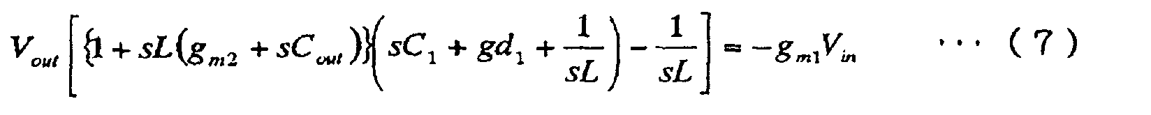
- Fig. 6 is a diagram showing an example of a drive circuit for a laser diode by means of a PMOS-FET, and Fig. 7 a diagram showing an equivalent circuit of the drive circuit shown in Fig. 6. The result of theoretical computation of resonance constant Q in this circuit will be presented below. In the discussion hereinafter, gm1 and gm2 represent mutual conductances, gd1 a drain conductance, L an inductance, and C capacitances.
- From Eq (2), we can derive V1 as follows.
- By substituting (2)' into (1), we can modify Eq (1) as follows.


- Then we obtain Vout/Vin as follows.

- Assuming gm2 (=200 mS) » sCout (= 5 mS), we obtain the following.

- From this, s, ω0, and Q are derived as follows.


- When specific parameters are substituted into the result of inequality (12), the Q factor becomes approximately 10. With the Q factor larger than 1 as in this case, there will occur peaking and ringing as shown in Fig. 5. It is seen from the above result that it is important to set the resonance constant Q at a possible minimum value in order to restrain the peaking and ringing. For suppressing the influence of the inductance L as much as possible to control the value of resonance constant Q to near 1, it is common practice to interpose a resistor in series with L. For example, since a source follower circuit permits an equivalent resistance to be freely controlled by electric current values, the source follower circuit is also interposed instead of the resistor in certain cases. Let us investigate a configuration incorporating the source follower circuit instead of the resistor.
- Fig. 8 is a diagram showing an example of the drive circuit for the laser diode by means of a simple source follower circuit, and Fig. 9 a diagram showing an equivalent circuit of Fig. 8. The result of theoretical computation of resonance constant Q in this circuit will be provided below. In the discussion hereinafter, gm1 and gm2 represent the mutual conductances, gd1 the drain conductance, L the inductance, and C the capacitances.
- Using the relation of Vgs1 = Vin - Vout, Eq (13) can be rewritten as follows.
- For Eq (14), since sCout ≈ 30 mS at gm2 ≈ 200 mS and f = 1 GHz, we can assume gm2 » sCout.


- By substituting Eq (14)' into Eq (13)', we obtain the following relation.
- Accordingly, Vout/Vin can be derived as follows.

- From this, s, ω0, and Q are obtained as follows.


- From the above computation result, the resonance frequency ω0 increased a little, but Q itself was not affected at all. Namely, it was found that the resonance constant Q itself did not vary depending upon whether the current source was the common source of PMOS-FET or the common drain circuit of NMOS-FET, and that there was little effect thereby. Since the value of Q itself was unable to be suppressed even by the attempt to control the influence of L by the method of simply interposing the resistor R as described above, it was difficult to restrain the ringing and peaking. Since the number of portions requiring supply of electric current increased in order to solve these issues, it was also difficult to drive the circuit by the low supply voltage of 3.3 V or the like.
- United States Patent No. 5,898,334 discloses a method of lowering the parasitic capacitance by means of a single drive source, but this method involves such requirements that the size of MQ1 has to be small and the gate voltage has to be large. For this reason, it is necessary to use the voltage of 5 V or more, which makes driving at a low supply voltage difficult and poses the problem of heat generation.
- The present invention has been accomplished under such circumstances and an object of the invention is to provide a drive circuit for a light emitting device that permits the driving at a low supply voltage, without occurrence of the ringing and peaking and with little influence of yield and dispersion.
- A drive circuit according to the present invention is a drive circuit for driving a light emitting device, which comprises a first source follower circuit comprising an NMOS-FET having a gate terminal and adapted to supply a drive current to the light emitting device according to an input voltage into the said gate terminal; a second source follower circuit comprising a first PMOS-FET having a gate terminal connected to a node downstream of the first source follower circuit; and a second PMOS-FET having a gate terminal and adapted to supply an electric current to the second source follower circuit according to an input voltage into the said gate terminal, wherein a potential between the first PMOS-FET and the second PMOS-FET is supplied as the input voltage to the gate terminal of the NMOS-FET.
- In this case, a voltage Vgs between the gate terminal of the NMOS-FET of the first source follower circuit and the source terminal located downstream thereof is proportional to a voltage Vgs between the gate terminal and source terminal of the first PMOS-FET having the gate terminal connected to the node downstream of the first source follower circuit. Therefore, while an electric current flowing in each MOS-FET is determined according to the voltage Vgs between the gate terminal and source terminal, the electric current flowing in the first PMOS-FET is in a proportional relation to the electric current flowing in the NMOS-FET. On the other hand, the electric current flowing in the first PMOS-FET is determined according to the input voltage into the gate terminal of the second PMOS-FET. Accordingly, the electric currents flowing in the first PMOS-FET and the NMOS-FET become constant if a fixed voltage is applied to the gate terminal of the second PMOS-FET.
- The potential at the node between the downstream side of the NMOS-FET of the first source follower circuit and the light emitting device can vary depending upon states of the light emitting device and peripheral circuits, but even with such variation the electric current flowing in the NMOS-FET rarely varies as long as the electric current flowing in the first PMOS-FET is kept constant. Since the Q factor of the circuit varies depending upon the electric current flowing in the NMOS-FET, if the constants of the circuit components are selected so as to make the Q factor low, use of the drive circuit of the present configuration makes it feasible to maintain the Q factor at a low level.
- Since the resonance constant Q can be made small in the present drive circuit as described above, it becomes feasible to suppress the ringing and peaking and drive the light emitting device on a stable basis. Since the number of components can be reduced, it is feasible to reduce the influence of yield and dispersion and reduce the cost. Since the impedance is low, the gate voltage can also be set low, thus enabling the driving at the low supply voltage. Further, since there arises no problem even with some parasitic capacitance, there is no need for employing the configuration for lowering the parasitic capacitance as before.
- In the drive circuit for the light emitting device, it is preferable to gradually apply the electric current to the light emitting device, for example, in a stepped pattern of about four steps, instead of increasing the electric current directly to a high level.
- Then the drive circuit for the light emitting device is characterized by comprising a PMOS-FET group for further supplying a drive current to the light emitting device through the node downstream of the second source follower circuit. Namely, when the drive current is supplied from the PMOS-FET group to the light emitting device, the total of the drive current supplied to the light emitting device can be increased.
- When the drive current is supplied to the light emitting device, for example, by four steps in this configuration, the drive current of the first step is given by use of the first and second source follower circuits and the second PMOS-FET, whereby it becomes feasible to make the resonance constant Q small, suppress the ringing and peaking, and implement the stable driving of the light emitting device. In this case, drive current increases of the rest three steps can be implemented by sequentially activating the PMOS-FET group. Since the present configuration obviates the need for using the aforementioned Q-factor variation limiting structure in the PMOS-FET group, it is feasible to decrease the number of components, reduce the influence of yield and product dispersion, and decrease the cost.
- Since the impedance is low, the gate voltage can be set low, thus enabling the driving at the low supply voltage. Further, since there arises no problem even with some parasitic capacitance, there is no need for employing the configuration of lowering the parasitic capacitance as before.
- In the present drive circuit for the light emitting, the mutual conductance of the first source follower circuit comprising the NMOS-FET has either value in a range of 10 mS (millisiemens) to 100 mS.
- Since the mutual conductance of the source follower circuit comprising the NMOS-FET has either value in the range of 10 mS to 100 mS, the resonance constant Q can be made small.
- A light emitting apparatus according to the present invention comprises a light emitting device and the drive circuit for the light emitting device in either of the configurations as described above.
- This configuration makes it feasible to suppress the ringing and peaking and implement stable light emission. Since the number of components can be reduced, it becomes feasible to reduce the influence of yield and dispersion and decrease the cost. Since the impedance is low, the gate voltage can be set low, thus enabling the driving at the low supply voltage.
-
- Fig. 1A is a diagram showing a configuration of a drive circuit for a light emitting device according to an embodiment.
- Fig. 1B is a circuit diagram of the part around the laser diode.
- Fig. 2 is a diagram showing an equivalent circuit of the source follower circuit part.
- Fig. 3A is a graph (simulation) showing time dependence of drive current in the drive circuit for the light emitting device according to the embodiment.
- Fig. 3B is a graph (actually measured values) showing time dependence of drive current in the drive circuit for the light emitting device according to the embodiment.
- Fig. 3C is a graph (actually measured values) showing time dependence of drive current in a drive circuit for a light emitting device according to a comparative example.
- Fig. 4 is a diagram showing a configuration of a conventional drive circuit for a light emitting device, presented as a comparative example.
- Fig. 5 is a diagram showing the simulation result of the conventional drive circuit for the light emitting device.
- Fig. 6 is a diagram showing an example of the drive circuit for the laser diode by means of a PMOS-FET.
- Fig. 7 is a diagram showing an equivalent circuit of Fig. 6.
- Fig. 8 is a diagram showing an example of the drive circuit for the laser diode by means of a simple source follower circuit.
- Fig. 9 is a diagram showing an equivalent circuit of Fig. 8.
-
- Fig. 1A is a diagram showing a configuration of the drive circuit for the light emitting device, in which the laser diode (light emitting device) 1 is illustrated as a bipolar transistor. Fig. 1B is a circuit diagram of the part around the laser diode 1. Namely, the laser diode 1 is illustrated as a transistor with the collector and base thereof shortcircuited for convenience' sake of description in Fig. 1A, but the laser diode 1 is one to be indicated by the symbol shown in Fig. 1B as a matter of fact.
- The laser diode 1 is grounded on the cathode side and a source terminal of source follower circuit 2 consisting of an NMOS-FET (field effect transistor) is connected to the anode side of the laser diode 1. A gate terminal of source follower circuit 3 consisting of a PMOS-FET (field effect transistor) is connected to the source terminal of the source follower circuit 2 consisting of the NMOS-FET. A PMOS-FET 4 is connected to a source terminal of the source follower circuit 3 consisting of the PMOS-FET to supply power to the source follower circuit 3 consisting of the PMOS-FET. The source follower circuit 3 of the PMOS-FET, and the PMOS-FET 4 constitute a source follower part 5 as a feedback circuit.
- A line 6 having an inductance L connects the laser diode 1 and the source follower circuit 2 consisting of the NMOS-FET to each other. Since the operation of the laser diode 1 as an electric circuit can be handled approximately as a transistor, it is assumed to be a transistor, and a capacitor Cout is connected to the emitter and collector of this transistor. Three PMOS-FETs 7a, 7b, 7c for driving the laser diode 1 are connected in parallel to the source terminal of the source follower circuit 2 consisting of the NMOS-FET, and constitute a PMOS-FET circuit 8.
- A capacitor C1 grounded at one end is connected to between the source terminal of the source follower circuit 2 consisting of the NMOS-FET, and the PMOS-FET circuit 8. The source of each of the PMOS-FETs 4, 7a, 7b, 7c and the drain of NMOS-FET 2 are connected to a power-supply potential.
- Fig. 2 is a diagram showing an equivalent circuit of the source follower part 5. The result of theoretical computation of the resonance constant Q in this circuit will be presented below. In the discussion hereinafter, gms1 and gms2 represent the mutual conductances, gd1 the drain conductance, L the inductance, and C the capacitances.
- Using the relation of Vgs1 = Vin - Vout, Eq (23) can be rewritten as follows.
- Further, the following relation holds.
- From the above equations, we can obtain the following relation.

- Concerning Eq (23), the mutual conductance gm1 of the source follower circuit 2 consisting of the NMOS-FET has either value in the range of 10 mS to 100 mS. This can make the resonance constant Q small. Concerning Eq (24), supposing gms is approximately 200 mS and f = 1GHz, sCout is approximately 30 mS and thus we can assume gm2 » sCout.
- By substituting (24)' into (23)' and arranging it, we obtain the following relation.

- Since gm2 is approximately 200 mS and gd1 is 1 mS, gm2 » gd1 and thus Vout/Vin becomes as follows.

- From the above, ω0 and Q are obtained as follows.

- Supposing f0 = 1.12 GHz, ω0 is ca. 7G, gm1/C1 ca. 14.7 G, gd1/C1 ca. 0.5 G, and 1/Lgm2 ca. 0.5 G. Thus the value of Q becomes ca. 0.445. It is seen from this result that the impedance of the source follower circuit eventually has the effect of decreasing the resonance constant Q because of the effect of the feedback loop. Namely, since the denominator of the resonance constant Q includes the impedance component of the source follower circuit, it acts to decrease Q.
- The present drive circuit for the light emitting device comprises the first source follower circuit 2 comprising the NMOS-FET (2) having the gate terminal and adapted to supply the drive current to the light emitting device 1 according to the input voltage into the gate terminal, the second source follower circuit 3 comprising the first PMOS-FET (3) having the gate terminal connected to the node (V1) downstream of the first source follower circuit 2, and the second PMOS-FET 4 having the gate terminal and adapted to supply the electric current to the second source follower circuit 3 according to the input voltage into the gate terminal, and is characterized in that the potential between the first PMOS-FET 3 and the second PMOS-FET 4 is supplied as the input voltage to the gate terminal of the NMOS-FET (2).
- The voltage Vgs between the gate terminal of the NMOS-FET (2) of the first source follower circuit 2 and the source terminal located downstream thereof is proportional to the voltage Vgs between the gate terminal and source terminal of the first PMOS-FET (3) having the gate terminal connected to the node (V1) downstream of the first source follower circuit 2. Therefore, while an electric current flowing in each MOS-FET is determined according to the voltage Vgs between the gate terminal and source terminal, the electric current flowing in the first PMOS-FET (3) is in a proportional relation to the electric current flowing in the NMOS-FET (2).
- On the other hand, the electric current flowing in the first PMOS-FET (3) is determined according to the input voltage into the gate terminal of the second PMOS-FET (4). Therefore, when the constant voltage is applied to the gate terminal of the second PMOS-FET (4), the electric currents flowing in the first PMOS-FET (3) and in the NMOS-FET (2) become constant.
- The potential at the node (V1) between the downstream side of the NMOS-FET (2) of the first source follower circuit and the laser diode 1 can vary depending upon states of the laser diode 1 and peripheral circuits, but even with such variation the electric current flowing in the NMOS-FET (2) rarely varies as long as the electric current flowing in the first PMOS-FET (3) is kept constant. Since the Q factor of the circuit varies depending upon the electric current flowing in the NMOS-FET (2), if the constants of the circuit components are selected so as to make the Q factor low, the Q factor can be maintained at a low level by use of the drive circuit of the present configuration.
- Since in the present embodiment the resonance constant Q can be made small as described above, it becomes feasible to suppress the ringing and peaking and implement the stable driving of the light emitting device. Since the number of components can be decreased, it is feasible to reduce the influence of yield and product dispersion and decrease the cost.
- Since the impedance can be controlled to a low level, the gate voltage can be set low, thus enabling the driving at the low supply voltage. Further, since there arises no problem with some parasitic capacitance, there is no need for employing the configuration of lowering the parasitic capacitance as before.
- In the case of the drive circuit for the light emitting device as shown in Figs. 1A and 1B, it is common practice to gradually apply the electric current to the laser diode 1, for example, in a stepped pattern of about four steps, instead of increasing the electric current directly to a high level. In the present embodiment, the source follower part 5 supplies the electric current of only the first step out of the four steps to the laser diode 1 by the feedback loop, and step-ups of the remaining three steps are implemented by the PMOS-FET circuit 8 comprised of a plurality of PMOS-FETs. The reason is that once the impedance level is fixed in a low state at the first stage of the initial lowest current, there is no need to decrease the impedance further.
- Namely, the electric current of the first step is first flowed by supplying the dc voltage Vg to the gate terminal of the first-stage PMOS-FET (4) and, subsequent thereto, the voltages Va, Vb, and Vc are sequentially supplied to the gates of the PMOS-FETs 7a, 7b, and 7c, respectively, constituting the PMOS-FET circuit 8. A large drive current can be supplied to the laser diode 1 by properly timing voltage pulses into the gate terminals of these PMOS-FETs 4, 7a, 7b, 7c to each other. Namely, the magnitude of the drive current supplied to the laser diode 1 is dependent upon the number of simultaneous pulses and the maximum drive current is supplied to the laser diode 1 when all pulses are at the same time.
- In order to realize the four steps in this configuration, the resonance constant Q can be made small by provision of the feedback circuit only in the part of the first step, which makes it feasible to suppress the ringing and peaking and implement the stable driving of the light emitting device.
- In this configuration, the remaining three steps are implemented by the driving with the PMOS-FET group 8 as before, which makes it feasible to decrease the number of components, reduce the influence of yield and product dispersion, and decrease the cost. Since the impedance can be controlled at a low level, the gate voltage can be set low, thus enabling the driving at the low supply voltage. The drive circuit for the light emitting device according to the present embodiment enables the laser diode 1 to be driven at the gate voltage of not more than 3.3 V. A plurality of laser diodes 1 can be disposed in the circuitry, and they can be connected in parallel.
- Fig. 3A is a graph (simulation) showing the time dependence of the drive current in the drive circuit for the light emitting device according to the embodiment. Fig. 3B is a graph (actually measured values) showing the time dependence of the drive current in the drive circuit for the light emitting device according to the embodiment, in which the pulse width of the drive current is 9.76 ns. Fig. 3C is a graph (actually measured values) showing the time dependence of the drive current in the drive circuit for the light emitting device as a comparative example shown in Fig. 4.
- As apparent from Figs. 3A, 3B, and 3C, the ringing and peaking as seen in the comparative example appears little in the drive circuit for the light emitting device according to the embodiment. This verifies that the drive circuit can adequately drive the laser diode 1.
- In the drive circuit for the light emitting device according to the present embodiment, as described above, since the resonance constant Q can be made small by using the feedback loop for the source follower circuit consisting of the NMOS-FET, it becomes feasible to suppress the ringing and peaking and implement the stable driving of the laser diode 1. Since the number of components can be decreased, it is feasible to reduce the influence of yield dispersion and decrease the cost. Since the impedance can be controlled at a low level, the gate voltage can be set low, thus enabling the driving at the low supply voltage. Further, since there arises no problem even with some parasitic capacitance, there is no need for employing the configuration of lowering the parasitic capacitance as before.
- As described above, the drive circuit for the light emitting device according to the present invention is constructed in the structure provided with the source follower circuit consisting of the NMOS-FET connected to the anode side of the light emitting device and adapted to directly drive the light emitting device, the source follower circuit consisting of the PMOS-FET the gate terminal of which is connected to the source terminal of the source follower circuit consisting of the NMOS-FET, and the PMOS-FET adapted to supply the electric current to the source follower circuit consisting of the PMOS-FET.
- This configuration makes the resonance constant Q small and thus makes it feasible to suppress the ringing and peaking and implement the stable driving of the light emitting device. Since the number of components can be decreased, it is feasible to reduce the influence of yield dispersion and decrease the cost. Since the impedance can be controlled at a low level, the gate voltage can be set low, thus enabling the driving at the low supply voltage. Further, since there arises no problem even with some parasitic capacitance, there is no need for employing the configuration of lowering the parasitic capacitance as before.
- The present invention may be applied to a drive circuit for a light emitting device.
Claims (4)
- A drive circuit for a light-emitting device, comprising:wherein a potential between said first PMOS-FET and said second PMOS-FET is supplied as said input voltage to said gate terminal of said NMOS-FET.a first source follower circuit comprising an NMOS-FET having a gate terminal and adapted to supply a drive current to said light emitting device according to an input voltage into the gate terminal;a second source follower circuit comprising a first PMOS-FET having a gate terminal connected to a node downstream of said first source follower circuit; anda second PMOS-FET having a gate terminal and adapted to supply an electric current to said second source follower circuit according to an input voltage into said gate terminal,
- The drive circuit according to Claim 1, wherein a mutual conductance of the source follower circuit comprising said NMOS-FET has either value in a range of 10 mS to 100 mS.
- The drive circuit according to Claim 1, comprising a PMOS-FET group for further supplying a drive current to said light emitting device through the node downstream of said second source follower circuit.
- A light emitting apparatus comprising said light emitting device and the drive circuit as set forth in Claim 1.
Applications Claiming Priority (3)
| Application Number | Priority Date | Filing Date | Title |
|---|---|---|---|
| JP2000219777 | 2000-07-19 | ||
| JP2000219777 | 2000-07-19 | ||
| PCT/JP2001/006242 WO2002007276A1 (en) | 2000-07-19 | 2001-07-18 | Light-emitting device drive circuit |
Publications (3)
| Publication Number | Publication Date |
|---|---|
| EP1311040A1 true EP1311040A1 (en) | 2003-05-14 |
| EP1311040A4 EP1311040A4 (en) | 2003-08-27 |
| EP1311040B1 EP1311040B1 (en) | 2007-06-06 |
Family
ID=18714497
Family Applications (1)
| Application Number | Title | Priority Date | Filing Date |
|---|---|---|---|
| EP01950022A Expired - Lifetime EP1311040B1 (en) | 2000-07-19 | 2001-07-18 | Light-emitting device drive circuit |
Country Status (8)
| Country | Link |
|---|---|
| US (1) | US6563849B2 (en) |
| EP (1) | EP1311040B1 (en) |
| JP (1) | JP3391784B2 (en) |
| KR (1) | KR100784505B1 (en) |
| CN (1) | CN1316699C (en) |
| AU (1) | AU2001271072A1 (en) |
| DE (1) | DE60128812T2 (en) |
| WO (1) | WO2002007276A1 (en) |
Cited By (1)
| Publication number | Priority date | Publication date | Assignee | Title |
|---|---|---|---|---|
| WO2012049516A1 (en) * | 2010-10-15 | 2012-04-19 | New Lighting Technology Limited | Illumination apparatus and method |
Families Citing this family (9)
| Publication number | Priority date | Publication date | Assignee | Title |
|---|---|---|---|---|
| WO2003096759A1 (en) * | 2001-03-30 | 2003-11-20 | Santur Corporation | High speed modulation of arrayed lasers |
| TW550977B (en) * | 2002-02-15 | 2003-09-01 | Ind Tech Res Inst | Control circuit for driving light emitting device |
| JP4072047B2 (en) * | 2002-11-29 | 2008-04-02 | 松下電器産業株式会社 | Laser diode drive device |
| JP4364664B2 (en) * | 2004-02-04 | 2009-11-18 | シャープ株式会社 | Light emitting diode drive circuit and optical transmitter for optical fiber link |
| US8000368B2 (en) * | 2006-07-26 | 2011-08-16 | Santur Corporation | Modulated semiconductor DFB laser array with a MEMS-based RF switch |
| JP5509662B2 (en) * | 2009-04-13 | 2014-06-04 | ソニー株式会社 | Laser drive device |
| KR20130012670A (en) | 2011-07-26 | 2013-02-05 | 삼성디스플레이 주식회사 | Backlight unit and current controlling method thereof |
| US11244452B2 (en) | 2017-10-16 | 2022-02-08 | Massachusetts Institute Of Technology | Systems, devices and methods for non-invasive hematological measurements |
| WO2021242983A1 (en) | 2020-05-28 | 2021-12-02 | Leuko Labs, Inc. | A method to detect white blood cells and/or white blood cell subtypes form non-invasive capillary videos |
Citations (3)
| Publication number | Priority date | Publication date | Assignee | Title |
|---|---|---|---|---|
| JPH04109687A (en) * | 1990-08-30 | 1992-04-10 | Ricoh Co Ltd | Semiconductor laser control device |
| JPH06132591A (en) * | 1992-10-21 | 1994-05-13 | Sumitomo Electric Ind Ltd | Semiconductor laser driving circuit |
| JP2000252521A (en) * | 1999-02-24 | 2000-09-14 | Nec Corp | Light emitting element drive circuit |
Family Cites Families (4)
| Publication number | Priority date | Publication date | Assignee | Title |
|---|---|---|---|---|
| JPH0731823B2 (en) | 1987-04-08 | 1995-04-10 | パイオニア株式会社 | Light source drive circuit |
| JP3725235B2 (en) * | 1996-03-29 | 2005-12-07 | 富士通株式会社 | Light emitting element driving circuit and light emitting device having the same |
| US5898334A (en) | 1997-05-12 | 1999-04-27 | Elantec Semiconductor, Inc. | Reduced output capacitance circuit for driving a grounded load in response to a stepped input |
| JP3405518B2 (en) * | 1998-01-29 | 2003-05-12 | 住友電気工業株式会社 | Semiconductor laser drive circuit |
-
2001
- 2001-07-18 AU AU2001271072A patent/AU2001271072A1/en not_active Abandoned
- 2001-07-18 DE DE60128812T patent/DE60128812T2/en not_active Expired - Lifetime
- 2001-07-18 WO PCT/JP2001/006242 patent/WO2002007276A1/en active IP Right Grant
- 2001-07-18 KR KR1020037000804A patent/KR100784505B1/en active IP Right Grant
- 2001-07-18 CN CNB018129692A patent/CN1316699C/en not_active Expired - Fee Related
- 2001-07-18 EP EP01950022A patent/EP1311040B1/en not_active Expired - Lifetime
- 2001-07-18 US US09/907,438 patent/US6563849B2/en not_active Expired - Lifetime
- 2001-07-18 JP JP2002513061A patent/JP3391784B2/en not_active Expired - Fee Related
Patent Citations (3)
| Publication number | Priority date | Publication date | Assignee | Title |
|---|---|---|---|---|
| JPH04109687A (en) * | 1990-08-30 | 1992-04-10 | Ricoh Co Ltd | Semiconductor laser control device |
| JPH06132591A (en) * | 1992-10-21 | 1994-05-13 | Sumitomo Electric Ind Ltd | Semiconductor laser driving circuit |
| JP2000252521A (en) * | 1999-02-24 | 2000-09-14 | Nec Corp | Light emitting element drive circuit |
Non-Patent Citations (4)
| Title |
|---|
| PATENT ABSTRACTS OF JAPAN vol. 016, no. 352 (E-1241), 29 July 1992 (1992-07-29) -& JP 04 109687 A (RICOH CO LTD), 10 April 1992 (1992-04-10) * |
| PATENT ABSTRACTS OF JAPAN vol. 018, no. 425 (E-1590), 9 August 1994 (1994-08-09) -& JP 06 132591 A (SUMITOMO ELECTRIC IND LTD), 13 May 1994 (1994-05-13) * |
| PATENT ABSTRACTS OF JAPAN vol. 2000, no. 12, 3 January 2001 (2001-01-03) -& JP 2000 252521 A (NEC CORP;NEC MIYAGI LTD), 14 September 2000 (2000-09-14) * |
| See also references of WO0207276A1 * |
Cited By (1)
| Publication number | Priority date | Publication date | Assignee | Title |
|---|---|---|---|---|
| WO2012049516A1 (en) * | 2010-10-15 | 2012-04-19 | New Lighting Technology Limited | Illumination apparatus and method |
Also Published As
| Publication number | Publication date |
|---|---|
| EP1311040B1 (en) | 2007-06-06 |
| CN1316699C (en) | 2007-05-16 |
| KR100784505B1 (en) | 2007-12-11 |
| KR20030023707A (en) | 2003-03-19 |
| CN1443386A (en) | 2003-09-17 |
| DE60128812D1 (en) | 2007-07-19 |
| JP3391784B2 (en) | 2003-03-31 |
| DE60128812T2 (en) | 2008-01-31 |
| AU2001271072A1 (en) | 2002-01-30 |
| EP1311040A4 (en) | 2003-08-27 |
| WO2002007276A1 (en) | 2002-01-24 |
| US6563849B2 (en) | 2003-05-13 |
| US20020048298A1 (en) | 2002-04-25 |
Similar Documents
| Publication | Publication Date | Title |
|---|---|---|
| US7521912B2 (en) | Power supply apparatus | |
| EP0701712B1 (en) | Voltage regulators | |
| KR101818313B1 (en) | Two-stage low-dropout linear power supply systems and methods | |
| US20160141833A1 (en) | Laser driver for driving laser diode | |
| EP1311040A1 (en) | Light-emitting device drive circuit | |
| US7869176B2 (en) | Surge protected power supply | |
| KR20230043983A (en) | Switch FET body current management device and method | |
| KR20210069115A (en) | Device for adjusting the bias voltage of a switching power supply | |
| US10749514B2 (en) | GaN based adjustable driver current circuit | |
| JP6097713B2 (en) | Light emitting element driving circuit, light source device, and light emitting element driving method | |
| US20190158027A1 (en) | High speed, high voltage, amplifier output stage using linear or class D topology | |
| US20230421046A1 (en) | Integrated gallium nitride power device with protection circuits | |
| EP3344013A1 (en) | Driver circuit of light sources, in particular for a vehicle light | |
| KR101391489B1 (en) | Low Dropout Voltage Regulator | |
| US20220418068A1 (en) | Pwm controlled power source and method | |
| JP2016171487A (en) | Drive circuit | |
| EP3344012B1 (en) | Driver circuit of light sources, in particular for a vehicle light | |
| US20190246475A1 (en) | Driver circuit for driving light emitting device | |
| US20180041115A1 (en) | Modulated power supply | |
| US6683500B2 (en) | Auto bias circuit for power amplifier using power MOSFET | |
| US20100244910A1 (en) | Sinusoidal waveform generation circuit | |
| US20020105289A1 (en) | Device and method for generating a high voltage | |
| US6791393B1 (en) | Anti-jitter circuits | |
| KR20040024789A (en) | Internal voltage generator for generating stable internal voltage | |
| EP1193850A1 (en) | Device and method for generating a high voltage |
Legal Events
| Date | Code | Title | Description |
|---|---|---|---|
| PUAI | Public reference made under article 153(3) epc to a published international application that has entered the european phase |
Free format text: ORIGINAL CODE: 0009012 |
|
| 17P | Request for examination filed |
Effective date: 20030114 |
|
| AK | Designated contracting states |
Designated state(s): AT BE CH CY DE DK ES FI FR GB GR IE IT LI LU MC NL PT SE TR |
|
| AX | Request for extension of the european patent |
Extension state: AL LT LV MK RO SI |
|
| A4 | Supplementary search report drawn up and despatched |
Effective date: 20030710 |
|
| RIC1 | Information provided on ipc code assigned before grant |
Ipc: 7H 01S 5/042 A Ipc: 7H 01L 33/00 B Ipc: 7H 05B 33/08 B Ipc: 7H 04B 10/04 B |
|
| RBV | Designated contracting states (corrected) |
Designated state(s): DE FR GB IT NL |
|
| 17Q | First examination report despatched |
Effective date: 20050310 |
|
| GRAP | Despatch of communication of intention to grant a patent |
Free format text: ORIGINAL CODE: EPIDOSNIGR1 |
|
| GRAS | Grant fee paid |
Free format text: ORIGINAL CODE: EPIDOSNIGR3 |
|
| GRAA | (expected) grant |
Free format text: ORIGINAL CODE: 0009210 |
|
| AK | Designated contracting states |
Kind code of ref document: B1 Designated state(s): DE FR GB IT NL |
|
| REG | Reference to a national code |
Ref country code: GB Ref legal event code: FG4D |
|
| REF | Corresponds to: |
Ref document number: 60128812 Country of ref document: DE Date of ref document: 20070719 Kind code of ref document: P |
|
| ET | Fr: translation filed | ||
| PLBE | No opposition filed within time limit |
Free format text: ORIGINAL CODE: 0009261 |
|
| STAA | Information on the status of an ep patent application or granted ep patent |
Free format text: STATUS: NO OPPOSITION FILED WITHIN TIME LIMIT |
|
| 26N | No opposition filed |
Effective date: 20080307 |
|
| REG | Reference to a national code |
Ref country code: FR Ref legal event code: PLFP Year of fee payment: 16 |
|
| REG | Reference to a national code |
Ref country code: DE Ref legal event code: R082 Ref document number: 60128812 Country of ref document: DE Representative=s name: MAUCHER JENKINS, DE Ref country code: DE Ref legal event code: R082 Ref document number: 60128812 Country of ref document: DE Representative=s name: MAUCHER JENKINS PATENTANWAELTE & RECHTSANWAELT, DE |
|
| REG | Reference to a national code |
Ref country code: FR Ref legal event code: PLFP Year of fee payment: 17 |
|
| REG | Reference to a national code |
Ref country code: FR Ref legal event code: PLFP Year of fee payment: 18 |
|
| PGFP | Annual fee paid to national office [announced via postgrant information from national office to epo] |
Ref country code: NL Payment date: 20180613 Year of fee payment: 18 |
|
| PGFP | Annual fee paid to national office [announced via postgrant information from national office to epo] |
Ref country code: FR Payment date: 20180612 Year of fee payment: 18 |
|
| PGFP | Annual fee paid to national office [announced via postgrant information from national office to epo] |
Ref country code: DE Payment date: 20180703 Year of fee payment: 18 Ref country code: IT Payment date: 20180713 Year of fee payment: 18 |
|
| PGFP | Annual fee paid to national office [announced via postgrant information from national office to epo] |
Ref country code: GB Payment date: 20180718 Year of fee payment: 18 |
|
| REG | Reference to a national code |
Ref country code: DE Ref legal event code: R119 Ref document number: 60128812 Country of ref document: DE |
|
| GBPC | Gb: european patent ceased through non-payment of renewal fee |
Effective date: 20190718 |
|
| PG25 | Lapsed in a contracting state [announced via postgrant information from national office to epo] |
Ref country code: GB Free format text: LAPSE BECAUSE OF NON-PAYMENT OF DUE FEES Effective date: 20190718 Ref country code: DE Free format text: LAPSE BECAUSE OF NON-PAYMENT OF DUE FEES Effective date: 20200201 Ref country code: NL Free format text: LAPSE BECAUSE OF NON-PAYMENT OF DUE FEES Effective date: 20190801 |
|
| REG | Reference to a national code |
Ref country code: NL Ref legal event code: MM Effective date: 20190801 |
|
| PG25 | Lapsed in a contracting state [announced via postgrant information from national office to epo] |
Ref country code: FR Free format text: LAPSE BECAUSE OF NON-PAYMENT OF DUE FEES Effective date: 20190731 |
|
| PG25 | Lapsed in a contracting state [announced via postgrant information from national office to epo] |
Ref country code: IT Free format text: LAPSE BECAUSE OF NON-PAYMENT OF DUE FEES Effective date: 20190718 |