EP1311048A2 - Power controller, power generation system and control method of power controller - Google Patents
Power controller, power generation system and control method of power controller Download PDFInfo
- Publication number
- EP1311048A2 EP1311048A2 EP02024975A EP02024975A EP1311048A2 EP 1311048 A2 EP1311048 A2 EP 1311048A2 EP 02024975 A EP02024975 A EP 02024975A EP 02024975 A EP02024975 A EP 02024975A EP 1311048 A2 EP1311048 A2 EP 1311048A2
- Authority
- EP
- European Patent Office
- Prior art keywords
- power
- charge
- discharge
- power generation
- voltage
- Prior art date
- Legal status (The legal status is an assumption and is not a legal conclusion. Google has not performed a legal analysis and makes no representation as to the accuracy of the status listed.)
- Withdrawn
Links
Images


Classifications
-
- H—ELECTRICITY
- H01—ELECTRIC ELEMENTS
- H01M—PROCESSES OR MEANS, e.g. BATTERIES, FOR THE DIRECT CONVERSION OF CHEMICAL ENERGY INTO ELECTRICAL ENERGY
- H01M8/00—Fuel cells; Manufacture thereof
- H01M8/04—Auxiliary arrangements, e.g. for control of pressure or for circulation of fluids
-
- H—ELECTRICITY
- H01—ELECTRIC ELEMENTS
- H01M—PROCESSES OR MEANS, e.g. BATTERIES, FOR THE DIRECT CONVERSION OF CHEMICAL ENERGY INTO ELECTRICAL ENERGY
- H01M8/00—Fuel cells; Manufacture thereof
- H01M8/04—Auxiliary arrangements, e.g. for control of pressure or for circulation of fluids
- H01M8/04298—Processes for controlling fuel cells or fuel cell systems
- H01M8/04313—Processes for controlling fuel cells or fuel cell systems characterised by the detection or assessment of variables; characterised by the detection or assessment of failure or abnormal function
- H01M8/04537—Electric variables
- H01M8/04604—Power, energy, capacity or load
-
- H—ELECTRICITY
- H01—ELECTRIC ELEMENTS
- H01M—PROCESSES OR MEANS, e.g. BATTERIES, FOR THE DIRECT CONVERSION OF CHEMICAL ENERGY INTO ELECTRICAL ENERGY
- H01M16/00—Structural combinations of different types of electrochemical generators
- H01M16/003—Structural combinations of different types of electrochemical generators of fuel cells with other electrochemical devices, e.g. capacitors, electrolysers
- H01M16/006—Structural combinations of different types of electrochemical generators of fuel cells with other electrochemical devices, e.g. capacitors, electrolysers of fuel cells with rechargeable batteries
-
- H—ELECTRICITY
- H01—ELECTRIC ELEMENTS
- H01M—PROCESSES OR MEANS, e.g. BATTERIES, FOR THE DIRECT CONVERSION OF CHEMICAL ENERGY INTO ELECTRICAL ENERGY
- H01M8/00—Fuel cells; Manufacture thereof
- H01M8/04—Auxiliary arrangements, e.g. for control of pressure or for circulation of fluids
- H01M8/04298—Processes for controlling fuel cells or fuel cell systems
- H01M8/04313—Processes for controlling fuel cells or fuel cell systems characterised by the detection or assessment of variables; characterised by the detection or assessment of failure or abnormal function
- H01M8/04537—Electric variables
- H01M8/04544—Voltage
- H01M8/04567—Voltage of auxiliary devices, e.g. batteries, capacitors
-
- H—ELECTRICITY
- H01—ELECTRIC ELEMENTS
- H01M—PROCESSES OR MEANS, e.g. BATTERIES, FOR THE DIRECT CONVERSION OF CHEMICAL ENERGY INTO ELECTRICAL ENERGY
- H01M8/00—Fuel cells; Manufacture thereof
- H01M8/04—Auxiliary arrangements, e.g. for control of pressure or for circulation of fluids
- H01M8/04298—Processes for controlling fuel cells or fuel cell systems
- H01M8/04313—Processes for controlling fuel cells or fuel cell systems characterised by the detection or assessment of variables; characterised by the detection or assessment of failure or abnormal function
- H01M8/04537—Electric variables
- H01M8/04604—Power, energy, capacity or load
- H01M8/04626—Power, energy, capacity or load of auxiliary devices, e.g. batteries, capacitors
-
- H—ELECTRICITY
- H01—ELECTRIC ELEMENTS
- H01M—PROCESSES OR MEANS, e.g. BATTERIES, FOR THE DIRECT CONVERSION OF CHEMICAL ENERGY INTO ELECTRICAL ENERGY
- H01M8/00—Fuel cells; Manufacture thereof
- H01M8/04—Auxiliary arrangements, e.g. for control of pressure or for circulation of fluids
- H01M8/04298—Processes for controlling fuel cells or fuel cell systems
- H01M8/04694—Processes for controlling fuel cells or fuel cell systems characterised by variables to be controlled
- H01M8/04858—Electric variables
- H01M8/04925—Power, energy, capacity or load
- H01M8/0494—Power, energy, capacity or load of fuel cell stacks
-
- H—ELECTRICITY
- H01—ELECTRIC ELEMENTS
- H01M—PROCESSES OR MEANS, e.g. BATTERIES, FOR THE DIRECT CONVERSION OF CHEMICAL ENERGY INTO ELECTRICAL ENERGY
- H01M8/00—Fuel cells; Manufacture thereof
- H01M8/04—Auxiliary arrangements, e.g. for control of pressure or for circulation of fluids
- H01M8/04298—Processes for controlling fuel cells or fuel cell systems
- H01M8/04694—Processes for controlling fuel cells or fuel cell systems characterised by variables to be controlled
- H01M8/04858—Electric variables
- H01M8/04925—Power, energy, capacity or load
- H01M8/04947—Power, energy, capacity or load of auxiliary devices, e.g. batteries, capacitors
-
- H—ELECTRICITY
- H02—GENERATION; CONVERSION OR DISTRIBUTION OF ELECTRIC POWER
- H02J—CIRCUIT ARRANGEMENTS OR SYSTEMS FOR SUPPLYING OR DISTRIBUTING ELECTRIC POWER; SYSTEMS FOR STORING ELECTRIC ENERGY
- H02J9/00—Circuit arrangements for emergency or stand-by power supply, e.g. for emergency lighting
- H02J9/04—Circuit arrangements for emergency or stand-by power supply, e.g. for emergency lighting in which the distribution system is disconnected from the normal source and connected to a standby source
- H02J9/06—Circuit arrangements for emergency or stand-by power supply, e.g. for emergency lighting in which the distribution system is disconnected from the normal source and connected to a standby source with automatic change-over, e.g. UPS systems
- H02J9/062—Circuit arrangements for emergency or stand-by power supply, e.g. for emergency lighting in which the distribution system is disconnected from the normal source and connected to a standby source with automatic change-over, e.g. UPS systems for AC powered loads
-
- H—ELECTRICITY
- H02—GENERATION; CONVERSION OR DISTRIBUTION OF ELECTRIC POWER
- H02J—CIRCUIT ARRANGEMENTS OR SYSTEMS FOR SUPPLYING OR DISTRIBUTING ELECTRIC POWER; SYSTEMS FOR STORING ELECTRIC ENERGY
- H02J1/00—Circuit arrangements for dc mains or dc distribution networks
- H02J1/10—Parallel operation of dc sources
- H02J1/108—Parallel operation of dc sources using diodes blocking reverse current flow
-
- H—ELECTRICITY
- H02—GENERATION; CONVERSION OR DISTRIBUTION OF ELECTRIC POWER
- H02J—CIRCUIT ARRANGEMENTS OR SYSTEMS FOR SUPPLYING OR DISTRIBUTING ELECTRIC POWER; SYSTEMS FOR STORING ELECTRIC ENERGY
- H02J2300/00—Systems for supplying or distributing electric power characterised by decentralized, dispersed, or local generation
- H02J2300/30—The power source being a fuel cell
-
- Y—GENERAL TAGGING OF NEW TECHNOLOGICAL DEVELOPMENTS; GENERAL TAGGING OF CROSS-SECTIONAL TECHNOLOGIES SPANNING OVER SEVERAL SECTIONS OF THE IPC; TECHNICAL SUBJECTS COVERED BY FORMER USPC CROSS-REFERENCE ART COLLECTIONS [XRACs] AND DIGESTS
- Y02—TECHNOLOGIES OR APPLICATIONS FOR MITIGATION OR ADAPTATION AGAINST CLIMATE CHANGE
- Y02B—CLIMATE CHANGE MITIGATION TECHNOLOGIES RELATED TO BUILDINGS, e.g. HOUSING, HOUSE APPLIANCES OR RELATED END-USER APPLICATIONS
- Y02B90/00—Enabling technologies or technologies with a potential or indirect contribution to GHG emissions mitigation
- Y02B90/10—Applications of fuel cells in buildings
-
- Y—GENERAL TAGGING OF NEW TECHNOLOGICAL DEVELOPMENTS; GENERAL TAGGING OF CROSS-SECTIONAL TECHNOLOGIES SPANNING OVER SEVERAL SECTIONS OF THE IPC; TECHNICAL SUBJECTS COVERED BY FORMER USPC CROSS-REFERENCE ART COLLECTIONS [XRACs] AND DIGESTS
- Y02—TECHNOLOGIES OR APPLICATIONS FOR MITIGATION OR ADAPTATION AGAINST CLIMATE CHANGE
- Y02E—REDUCTION OF GREENHOUSE GAS [GHG] EMISSIONS, RELATED TO ENERGY GENERATION, TRANSMISSION OR DISTRIBUTION
- Y02E60/00—Enabling technologies; Technologies with a potential or indirect contribution to GHG emissions mitigation
- Y02E60/10—Energy storage using batteries
-
- Y—GENERAL TAGGING OF NEW TECHNOLOGICAL DEVELOPMENTS; GENERAL TAGGING OF CROSS-SECTIONAL TECHNOLOGIES SPANNING OVER SEVERAL SECTIONS OF THE IPC; TECHNICAL SUBJECTS COVERED BY FORMER USPC CROSS-REFERENCE ART COLLECTIONS [XRACs] AND DIGESTS
- Y02—TECHNOLOGIES OR APPLICATIONS FOR MITIGATION OR ADAPTATION AGAINST CLIMATE CHANGE
- Y02E—REDUCTION OF GREENHOUSE GAS [GHG] EMISSIONS, RELATED TO ENERGY GENERATION, TRANSMISSION OR DISTRIBUTION
- Y02E60/00—Enabling technologies; Technologies with a potential or indirect contribution to GHG emissions mitigation
- Y02E60/30—Hydrogen technology
- Y02E60/50—Fuel cells
Definitions
- the present invention relates to a power controller that performs electric power generation by using DC power generation means, for example, a fuel cell, or the like.
- a system shown in Figure 7 is known as a fuel cell power generation system (for example, refer to Japanese Patent Laid-Open No. 6-325774).
- a fuel cell 41 makes hydrogen, supplied by hydrogen supply means 42, and oxygen in air, which is supplied by air supply means 43, react in a main body of the fuel cell to generate DC power, which is converted into AC power by a power converter 44 and is outputted.
- a controller 45 can perform control so as to variably output electric power by electrical discharge from a charge and discharge apparatus 46 or charge to the charge and discharge apparatus 46 even if the generated power of the main body 41 of the fuel cell is fixed, by controlling the charge and discharge apparatus 46 and power converter 44.
- the charge and discharge apparatus 46 does not have means of controlling charge and discharge. Hence, it is difficult to control the charge and discharge of the charge and discharge apparatus 46 in high accuracy by compensating the difference between the output of the main body 41 of the fuel cell and ratings of power storage means such as a secondary cell in the charge and discharge apparatus 46.
- FIG. 8 shows a configuration of a fuel cell power generation system according to a second conventional example.
- a fuel cell 51 is a main body of a fuel cell to generate DC power by reacting hydrogen with oxygen in air.
- a DC/DC converter 52 boosts a voltage of DC power of the fuel cell 51.
- a power converter 53 (inverter) converts the DC power, boosted by the DC/DC converter 52, into AC power to output the AC power to an electric power load 55.
- a controller 54 is the means of detecting a load current of the electric power load 55 by a load current detector 56 and controlling a two-way DC/DC converter 57, the DC/DC converter 52, and the power converter 53.
- the controller 54 stores electric power in a storage battery 58 through the two-way DC/DC converter 57 when a value of an output current from the main body 51 of the fuel cell according to the load current of electric power load 55 exceeds a load current value.
- the controller 54 supplies the electric power of the storage battery 58 to the electric power load 55 through the two-way DC/DC converter 57.
- the fuel cell power generation system has a configuration in which the power converter 53 is connected to the two-way DC/DC converter 57 for the charge and discharge control of the storage battery 58 coupled with an output of the DC/DC converter 52 that boosts DC power to a voltage necessary for converting DC power into AC power.
- This system is made not only to control an output of the main body 51 of the fuel cell by the DC/DC converter 52, but also to raise charge and discharge efficiencies of the storage battery 58 by controlling the two-way DC/DC converter 57. Accordingly, charge from the fuel cell 51 to the storage battery 58 is performed through two voltage control means of the DC/DC converter 52 and two-way DC/DC converter 57.
- the present invention provides a fuel cell power controller, which quickly corresponds to a change of electric power demand, highly effectively generates electric energy required, and is highly economical and reliable, a power generation system using it, or the like.
- the 1st invention of the present invention is a power controller comprising:
- the 2nd invention of the present invention is the power controller according to the 1st invention, wherein the control means performs control of making the charge and discharge means perform the charge operation when the external power load is low, and making the charge and discharge means perform the discharge operation when the external power load is high.
- the 3rd invention of the present invention is the power controller according to the 1st invention, wherein the amount of converted voltage between an output of the DC power generation means and an input of the power storage means is smaller than the amount of converted voltage between an output of the DC power generation means and an input of the DC/DC converter of the power conversion means.
- the 4th invention of the present invention is the power controller according to the 1st invention, wherein the charge and discharge means comprises:
- the 5th invention of the present invention is the power controller according to the 1st invention, wherein the charge and discharge means comprises:
- the 6th invention of the present invention is the power controller according to the 1st invention, further comprising output voltage detection means of detecting an output voltage of the DC power generation means, wherein on the basis of the detected output voltage and the detected load power, the control means makes the charge and discharge means perform the charge operation when the detected output voltage is high and the detected load power is low, and makes the charge and discharge means perform the discharge operation when the detected output voltage is low and the detected load power is high.
- the 7th invention of the present invention is the power controller according to the 1st invention, further comprising power storage detection means of detecting power storage of the power storage means, wherein the control means controls operation of the charge and discharge means on the basis of the detected power storage.
- the 8th invention of the present invention is the power controller according to the 6th invention, further comprising load power measurement means of measuring the detected electric energy as a function of time, wherein a power generation schedule of the DC power generation means is determined on the basis of electric energy measured beforehand by the electric load power measurement means.
- the 9th invention of the present invention is a power generation system comprising:
- the 10th invention of the present invention is a control method of the power controller according to the 1st invention, wherein the electric energy is measured as a function of time, and a power generation schedule of DC power generation means is determined on the basis of the electric energy obtained by the measurement.
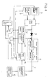
- Figure 1 is a block diagram of a fuel cell power generation apparatus in a first embodiment of the present invention.
- Fuel gas supply means 2 which contains hydrogen, such as a refining machine, a hydrogen-absorbing alloy, and a hydrogen cylinder, and oxidant gas supply means 3, which contains oxygen, such as a blower and a ventilation pump are connected to a fuel cell 1 that corresponds to the DC power generation means of the present invention.
- hydrogen such as a refining machine, a hydrogen-absorbing alloy, and a hydrogen cylinder
- oxidant gas supply means 3 which contains oxygen, such as a blower and a ventilation pump are connected to a fuel cell 1 that corresponds to the DC power generation means of the present invention.
- Power conversion means 4 is a means of converting a DC power into a AC power and has a configuration in which firstly the converter section 5 boosts a DC voltage in regard to the DC power from the fuel cell 1 and secondary the inverter section 6 converts the DC power having boosted voltage into the AC power to be outputted.
- An output line 7 is a means electrically connected to the power conversion means 4, and also is electrically connected to an electric power load 10.
- load power detection means 9 is a means of detecting the electric power outputted through the output line 7 on the basis of the operation of the electric power load 10.
- a secondary cell 11 corresponds to the power storage means of the present invention, and is means of charging and storing electric power, and discharging the stored electric power.
- Charge control means 12 is a means of converting DC power of the fuel cell 1 into a suitable voltage as the charging voltage of the secondary cell 11 and charging the secondary cell 11, and is implemented with, for example, a step-up and step-down voltage chopper circuit.
- discharge control means 13 is a means of converting the stored power to be discharged from the secondary cell 11 into substantially the same voltage as a DC output voltage of the fuel cell 1 and outputting the power to the power conversion means 4, and is implemented with, for example, a step-up and step-down voltage chopper circuit.
- a back flow preventing diode 14 is means of preventing the back flow of DC power from the discharge control means 13 to the fuel cell 1.
- Fuel cell control means 15 is a means of controlling the supply quantity of a fuel gas from the fuel gas supply means 2 to the fuel cell 1 and/or the supply quantity of an oxidant gas from the oxidant gas supply means 3 to the fuel cell 1, and of controlling an input and an output of storage power of the secondary cell 11 by controlling the charge control means 12 and discharge control means 13 according to the electric power load 10.
- An purpose of installing the secondary cell 11 is to prevent the deterioration of economy due to the excess or deficiency of output power to load power in system interconnection by using the charge and discharge of the secondary cell 11.
- the generated direct current is sent to the power conversion means 4.
- the direct current is converted into alternating current of the same voltage as that of the electric power load 10 by the inverter section 6 and is supplied to the electric power load 10 through the output line 7.
- the fuel cell control means 15 makes the secondary cell 11 complement the shortfall of the generated output for the electric power load 10 through the discharge control means 13.
- the output voltage from the fuel cell 1 is converted into a voltage substantially equal to the charge voltage of the secondary cell 11 by the charge control means 12.
- the output voltage from the secondary cell 11 is converted into a voltage substantially equal to the output voltage of the fuel cell 1 by the discharge control means 13 for the power to be outputted to the converter section 5 of the power conversion means 4.
- references of the step-up and step-down voltages can be either the output voltage of the fuel cell 1 or the charge and discharge voltages of the secondary cell 11.
- the output voltage of the fuel cell 1 may be a value obtained by measuring the fuel cell 1, or may be a value (fixed value) set beforehand on the basis of ratings etc.
- charge to the secondary cell 11 is made by directly taking electric power from the output of fuel cell 1 to the charge control means 12. Furthermore, an output from the secondary cell 11 to the power conversion means 4 is matched to the output voltage of the fuel cell 1 immediately before converter section 5.
- voltage conversion quantity to the secondary cell 11 by the charge control means 12 is extremely small in comparison with a second conventional example shown in Figure 8, that is, several volts to tens of volts .
- voltage conversion quantity to the power conversion means 4 by the discharge control means 13 is also small, that is, several volts to tens of volts.
- the charge and discharge efficiencies of the secondary cell 11 is 92 to 93%, it is possible to raise the total charge and discharge energy efficiencies at the time of using the secondary cell 11.
- this embodiment can also be constituted as shown in Figure 9. Points different from the configuration shown in Figure 1 are as follows.
- the back flow preventing diode 14 is omitted, and two systems of outputs of the fuel cell 1 are provided.
- One system is used as a connection path 100a, connected directly to the converter section 5 of the power conversion means 4, and the other system is used as the connection path 100b, connected to the charge control means 12.
- a connection path 100c that directly connects the discharge control means 13 to the converter sections 5 of the power conversion means 4 is provided. In this case, it is possible to completely prevent an output of the discharge control means 13 from flowing backward to the fuel cell 1 or charge control means 12 in a configuration that is simpler and less expensive than that of Figure 1.
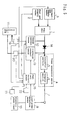
- Figure 3 is a block diagram of a fuel cell power generation apparatus in a second embodiment of the present invention.
- Charge and discharge control means 18 is the means of storing DC power, generated in the fuel cell 1, in the secondary cell 11 as power storage means, and controlling charge and discharge for outputting the stored power from the secondary cell 11 to the converter 5 of the power conversion means 4, and is constituted of, for example, a step-up and step-down voltage chopper circuit etc.
- Current switching means 16 and 17 are the means of switching the current directions of charge from the fuel cell 1 and discharge to the converter 5 of the power conversion means 4, and the current switching means 16 performs switching so as to connect the charge and discharge control means 18 to an output terminal of the fuel cell 1 or an output terminal of the secondary cell 11.
- the current switch means 17 performs switching so as to connect the charge and discharge control means 18 to an input terminal of the converter 5 of the power conversion means 4 or an input terminal of the secondary cell 11.
- the current switching means 16 and 17 are constituted of semiconductor switches, mechanical switches, or the like.
- the fuel cell control means 15 controls the current switching means 16 so as to connect an output terminal of the secondary cell 11 to an input terminal of the charge and discharge control means 18, and controls the current switch means 17 so as to connect an output terminal of the charge and discharge control means 18 to an input terminal of the converter 5 of the power conversion means 4, in order to supply the shortfall of the generated power to the electric power load 10 from the secondary cell 11.
- the fuel cell control means 15 controls the current switching means 16 so as to connect an output terminal of the fuel cell 1 to an input terminal of the charge and discharge control means 18, and controls the current switching means 17 so as to connect an output terminal of the charge and discharge control means 18 to an input terminal of the secondary cell 11, in order to charge the secondary cell 11.
- this embodiment can be also constituted as shown in Figure 10 similarly to the first embodiment. Points different from the configuration shown in Figure 3 are as follows . That is, the back flow preventing diode 14 is omitted, and two systems of outputs of the fuel cell 1 are provided. One system is used as a connection path 101a connected directly to the converter section 5 of the power conversion means 4, and the other system is used as the connection path 101b connected to the current switching means 16. Moreover, a connection path 101c that directly connects the current switching means 17 to the converter sections 5 of the power conversion means 4 is provided.
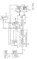
- FIG 4 is a block diagram of a fuel cell power generation apparatus in a third embodiment of the present invention.
- the same numerals are assigned to parts having the same functions as those of the fuel cell power generation apparatus of the first embodiment shown in Figure 1 and the fuel cell power generation apparatus of the second embodiment shown in Figure 3, and the detailed description of those functions will be omitted as those corresponding to those in Figures 1 and 3.
- a current sensor 19 is the means of detecting a charge current at the time when electric power by a power generation reaction from the fuel cell 1 is charged to the secondary cell 11 through the charge control means 12.
- a current sensor 20 is the means of detecting a discharge current at the time when stored electric power from the secondary cell 11 is discharged to the power conversion means 4 through the discharge control means 13.
- the fuel cell control means 15 always monitors a charge current from the current sensor 19 and a discharge current from the current sensor 20, and always grasps the stored electric energy of the secondary cell 11 by performing time integration and addition respectively.
- the fuel cell control means 15 stops electrical discharge by controlling the discharge control means 13 when the electric power storage becomes equal to or less than the first power storage.
- the first power storage is a lower limit of a region suitable for charge-discharge characteristics of the remaining battery capacity that is a State of Charge (SOC) or Depth of Discharge (DOD) of the secondary cell 11, and is set at, for example, about 50% of battery capacity.
- the fuel cell control means 15 charges the secondary cell 11 in a time zone when the electric power load of fuel cell 1 is low and an output voltage of the fuel cell 1 suitable for the charge of the secondary cell 11 is high. At this time, the fuel cell control means 15 stops electrical charge by controlling the charge control means 12 when the power storage becomes equal to or more than the second power storage.
- the second electric power storage is a highest limit of a region suitable for charge-discharge characteristics of the remaining battery capacity that is the State of Charge (SOC) or Depth of Discharge (DOD) of the secondary cell 11, and is set at, for example, about 80 to 90% of the battery capacity.
- the electric power storage of the secondary cell 11 is calculated on the basis of values detected by the current sensor 19 for detecting a charge current, and the current sensor 20 for detecting a discharge current, it can be possible to perform control operation based on the electric power storage in secondary cell 11 that is directly measured.
- FIG 5 is a block diagram of a fuel cell power generation apparatus in a fourth embodiment of the present invention.
- the same numerals are assigned to parts having the same functions as those of the fuel cell power generation apparatus of the first embodiment shown in Figure 1, the fuel cell power generation apparatus of the second embodiment shown in Figure 3, and the fuel cell power generation apparatus of the third embodiment shown in Figure 4, and the detailed description of those functions will be omitted as those corresponding to those in Figures 1, 3, and 4.
- This embodiment is characterized by the configuration of inputting to the fuel cell control means 15 a timing signal from timing means 21 such as a timer that measures time, and power consumption pattern information from electric energy memory means 22 such as semiconductor memory that stores power consumption at each time.
- timing means 21 such as a timer that measures time
- power consumption pattern information from electric energy memory means 22 such as semiconductor memory that stores power consumption at each time.
- the fuel cell control means 15 makes the electric energy memory means 22 store the electric energy detected by the load power detection means 9 as electric energy monitor information (relation between time and power consumption during a day) with regarding electric power to time according to the timing means 21. Then, on the basis of this electric energy monitor information, the fuel cell control means 15 outputs signals to the fuel gas supply means 2 and oxidant gas supply means 3 so that an electric power output after storage may become the same output at each timing corresponding to the electric energy monitor information. In addition, the fuel cell control means 15 charges the secondary cell 11 through the charge control means 12 in a time zone when the electric power load of fuel cell 1 is low and an output voltage of the fuel cell 1 suitable for the charge of the secondary cell 11 is high and secures charge time.
- the fuel cell control means 15 charges the secondary cell 11 at an every predetermined operation time on the basis of an electric energy pattern stored in the electric energy memory means 22, in a time zone when an output of power generation from the fuel cell 1 is a predetermined output or less, until electric power storage reaches full electric power storage through the charge control means 12, and charge time when the electric power storage reaches the full electric power storage exceeds predetermined time.
- "every predetermined operation time” means a time interval when refresh charge operation indispensable for excellently maintaining charge and discharge characteristics of the secondary cell 11 that is the power storage means is performed, and the interval is once a week or ten days. Furthermore, “until charge time when the electric power storage reaches the full electric power storage exceeds predetermined time” means “until an end of constant-voltage charge (forced charge) for completing the charge operation after the secondary cell 11 reaches full charge”, and "predetermined time” is the time when a state that a charge current becomes almost zero elapses for 2 to 3 hours.
- the fuel cell control means 15 charges the secondary cell 11 on the basis of the electric energy pattern, stored in the electric energy memory means 22, in a time zone when a power generation output from the fuel cell is a predetermined output or less until the electric power storage reaches the full electric power storage through the charge control means 12, and the charge time reaching the full electric power storage exceeds the predetermined time.
- the regular charge refresh operation of the secondary cell 11 can be secured, the life property of the secondary cell 11 improves greatly.
- Figure 6 is a block diagram of a fuel cell power generation apparatus in a fifth embodiment of the present invention.
- the same numerals are assigned to parts having the same functions as those of the fuel cell power generation apparatus of the first embodiment shown in Figure 1, and the fuel cell power generation apparatus of the second embodiment shown in Figure 3, and the detailed description of those functions will be omitted as those corresponding to those in Figures 1 and 3.
- This embodiment is characterized by the configuration that fuel cell output voltage detection means 23 detecting an output voltage of the fuel cell 1 is installed to correct the quantity of a step-up voltage or a step-down voltage in the charge and discharge control to the secondary cell 11 due to the decrease of an output voltage to an output current corresponding to an electric power load in connection with the aged degradation or the like of the fuel cell 1.
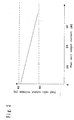
- an output voltage of the fuel cell 1 generally has a characteristic of decreasing with the increase in an output current of the fuel cell 1 as shown in Figure 2 along with aged degradation etc. this output characteristic itself shifts to the direction of decreasing to the voltage as a whole.
- the fuel cell control means 15 always monitors an output voltage of the fuel cell 1 to the load power of the electric power load 10 by the fuel cell output voltage detection means 23 and load power detection means 9. When a shift (output voltage decrease) of an output voltage characteristic to the load power of the fuel cell 1 arises, the fuel cell control means 15 adjusts the voltage difference as correction quantity of a step-up voltage level or a step-down voltage level in the charge-discharge control of the charge control means 12 and discharge control means 13 of the secondary cell 11 as power storage means.
- the fuel cell control means 15 always monitors an output voltage of the fuel cell 1 to properly secure the correction quantity of a step-up voltage or a step-down voltage in charge and discharge control to the power storage means for the decrease of an output voltage to an output current corresponding to the electric power load according to the aged degradation of the output characteristic or the like. Hence, it is possible to provide a power generation apparatus that has high reliability and high maintainability.
- the fuel cell 1 is an example of the DC power generation means of the present invention
- the secondary cell 11 is an example of the power storage means of the present invention
- the converter section 5 is an example of the DC/DC converter of the present invention
- the power conversion means 4 is an example of the power conversion means of the present invention
- the load power detection means 9 is an example of the detection means of the present invention
- the fuel cell control means 15 is an example of the control means of the present invention.
- the charge control means 12 is an example of the charge-side conversion means of the charge and discharge means of the present invention
- the discharge control means 13 is an example of the discharge-side conversion means of the charge and discharge means of the present invention
- the charge and discharge control means 18 is an example of the common conversion means of the charge and discharge means of the present invention
- the current switching means 16 is an example of the first control switch of the present invention
- the current switching means 17 is an example of the second control switch of the present invention.
- the back flow preventing diode 14, and the connection paths 100a, 100b, 100c, 101a, 101b, and 101c are included in the charge and discharge means of the present invention.
- the fuel cell output voltage detection means 23 is an example of the output voltage detection means of the present invention
- a set of current sensors 19 and 20 and fuel cell control means 15 is an example of the electric power storage detection means of the present invention.
- a set of timing means 21 and fuel cell control means 15 is an example of the load power measurement means of the present invention
- the electric energy memory means 22 is the means included in the control means of the present invention.
- electric energy monitor information stored in the electric energy memory means 22 is an example of the premeasured electric energy of the present invention.
- the present invention can be also realized as a power controller in the configuration of omitting the fuel cell 1, fuel gas supply means 2 , oxidant gas supply means 3, and electric power load 10 from the configuration of each embodiment.
- the DC power generation means need not be limited to a fuel cell, and is not limited to its type so long as it is an apparatus which can generate DC power, such as a battery, a gas turbine power generator, and a thermoelectric generator using the Seebeck effect.
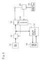
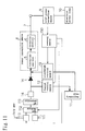
- the configuration of using a gas turbine power generator is shown in Figure 11.
- the gas turbine power generator comprises : a gas turbine 112 operating with a city gas supplied from a city gas supply section 110 controlled by control means 150, and air supplied from an air supply section 111 controlled by the control means 150; an AC generator 113 connected to the gas turbine 112; and an AC-DC converter 114 that converts a high frequency AC output of the AC generator 113 into DC power.
- the present invention can provide a power controller with high economy and reliability that improves the energy efficiency of power storage means or the like.
Abstract
power storage means of storing DC power outputted from DC power generation means that generates DC power;
power conversion means including at least a DC/DC converter that converts a voltage when receiving a DC input;
charge and discharge means of discharging electric power from the power storage means to the power conversion means and of charging DC power from the DC power generation means in the power storage means, the charge and discharge means being provided among the DC power generation means, the power storage means and the power conversion means;
detection means of detecting electric energy of an external power load to which power from at least the power conversion means is supplied; and
control means of controlling operation of the charge and discharge means on the basis of the detected electric energy.
Description
- The present invention relates to a power controller that performs electric power generation by using DC power generation means, for example, a fuel cell, or the like.
- Heretofore, a system shown in Figure 7 is known as a fuel cell power generation system (for example, refer to Japanese Patent Laid-Open No. 6-325774). In Figure 7, a
fuel cell 41 makes hydrogen, supplied by hydrogen supply means 42, and oxygen in air, which is supplied by air supply means 43, react in a main body of the fuel cell to generate DC power, which is converted into AC power by apower converter 44 and is outputted. Acontroller 45 can perform control so as to variably output electric power by electrical discharge from a charge anddischarge apparatus 46 or charge to the charge anddischarge apparatus 46 even if the generated power of themain body 41 of the fuel cell is fixed, by controlling the charge anddischarge apparatus 46 andpower converter 44. - Nevertheless, though it is necessary in such a fuel cell power generation system to match an output voltage of the
main body 41 of the fuel cell to charge and discharge voltages of the charge anddischarge apparatus 46, the charge anddischarge apparatus 46 does not have means of controlling charge and discharge. Hence, it is difficult to control the charge and discharge of the charge anddischarge apparatus 46 in high accuracy by compensating the difference between the output of themain body 41 of the fuel cell and ratings of power storage means such as a secondary cell in the charge anddischarge apparatus 46. - The following system is conceivable for canceling such a fault. Figure 8 shows a configuration of a fuel cell power generation system according to a second conventional example. In Figure 8, a
fuel cell 51 is a main body of a fuel cell to generate DC power by reacting hydrogen with oxygen in air. A DC/DC converter 52 boosts a voltage of DC power of thefuel cell 51. A power converter 53 (inverter) converts the DC power, boosted by the DC/DC converter 52, into AC power to output the AC power to anelectric power load 55. Acontroller 54 is the means of detecting a load current of theelectric power load 55 by aload current detector 56 and controlling a two-way DC/DC converter 57, the DC/DC converter 52, and thepower converter 53. - The
controller 54 stores electric power in astorage battery 58 through the two-way DC/DC converter 57 when a value of an output current from themain body 51 of the fuel cell according to the load current ofelectric power load 55 exceeds a load current value. When a value of the output current from themain body 51 of the fuel cell is insufficient for the load current value, thecontroller 54 supplies the electric power of thestorage battery 58 to theelectric power load 55 through the two-way DC/DC converter 57. - The fuel cell power generation system according to the above-mentioned second conventional example (Figure 8) has a configuration in which the
power converter 53 is connected to the two-way DC/DC converter 57 for the charge and discharge control of thestorage battery 58 coupled with an output of the DC/DC converter 52 that boosts DC power to a voltage necessary for converting DC power into AC power. - This system is made not only to control an output of the
main body 51 of the fuel cell by the DC/DC converter 52, but also to raise charge and discharge efficiencies of thestorage battery 58 by controlling the two-way DC/DC converter 57. Accordingly, charge from thefuel cell 51 to thestorage battery 58 is performed through two voltage control means of the DC/DC converter 52 and two-way DC/DC converter 57. - Nevertheless, since there is large difference between charge and discharge voltages of the
storage battery 58 and an output voltage boosted by the DC/DC converter 52 (in general, the output voltage boosted by the DC/DC converter 52 is higher) , it is necessary to increase the difference between step-up voltages and step-down voltages of the two-way DC/DC converter 57 according to the above difference. Hence, it is difficult to raise power conversion efficiency. - Moreover, there are issues that operating economy is low since total power conversion efficiency which is a product of a power conversion efficiency of the two-way DC/
DC converter 57 and charge and discharge efficiencies of thestorage battery 58 becomes low, in addition, cost also becomes high since a price of the two-way DC/DC converter 57 itself is also high. - In consideration of the above-mentioned issues, the present invention provides a fuel cell power controller, which quickly corresponds to a change of electric power demand, highly effectively generates electric energy required, and is highly economical and reliable, a power generation system using it, or the like.
- The 1st invention of the present invention is a power controller comprising:
- power storage means of storing DC power outputted from DC power generation means that generates DC power;
- power conversion means of including at least a DC/DC converter that converts a voltage when receiving a DC input;
- charge and discharge means of discharging electric power from the power storage means to the power conversion means and of charging DC power from the DC power generation means in the power storage means, the charge and discharge means being provided among the DC power generation means, the power storage means and the power conversion means;
- detection means of detecting electric energy of an external power load to which power from at least the power conversion means is supplied; and
- control means of controlling operation of the charge and discharge means on the basis of the detected electric energy, wherein the charge and discharge means has a DC/DC conversion function , converts an output voltage of the DC power generation means into a charge voltage of the power storage means, and converts a discharge voltage of the power storage means into an output voltage of the DC power generation means.
-
- The 2nd invention of the present invention is the power controller according to the 1st invention,
wherein the control means performs control of making the charge and discharge means perform the charge operation when the external power load is low, and making the charge and discharge means perform the discharge operation when the external power load is high. - The 3rd invention of the present invention is the power controller according to the 1st invention,
wherein the amount of converted voltage between an output of the DC power generation means and an input of the power storage means is smaller than the amount of converted voltage between an output of the DC power generation means and an input of the DC/DC converter of the power conversion means. - The 4th invention of the present invention is the power controller according to the 1st invention,
wherein the charge and discharge means comprises: - charge side conversion means of converting an output voltage of the DC power generation means into a charge voltage of the power storage means; and
- discharge side conversion means of converting a discharge voltage of the power storage means into an output voltage of the DC power generation means.
-
- The 5th invention of the present invention is the power controller according to the 1st invention,
wherein the charge and discharge means comprises: - common conversion means of performing a charge side conversion operation in which an output voltage of the DC power generation means is converted into the charge voltage of the power storage means or a discharge side conversion operation
- in which a discharge voltage of the power storage means is converted into an output voltage of the DC power generation means;
- a first control switch of performing control so that an input side of the common conversion means is connected to an output side of the DC power generation means or an output side of the power storage means; and
- a second control switch of performing control so that an output side of the common conversion means is connected to an input side of the DC/DC converter or an input side of the power storage means, and
- when the charge side conversion operation is performed, the first control switch connects the output side of the DC power generation means to the input side of the common conversion means while the second control switch connects the output side of the common conversion means to the input side of the power storage means, and
- when the discharge side conversion operation is performed, the first control switch connects the output side of the power storage means to the input side of the common conversion means while the second control switch connects the output side of the common conversion means to the input side of the DC/DC converter.
-
- The 6th invention of the present invention is the power controller according to the 1st invention, further comprising output voltage detection means of detecting an output voltage of the DC power generation means,
wherein on the basis of the detected output voltage and the detected load power, the control means makes the charge and discharge means perform the charge operation when the detected output voltage is high and the detected load power is low, and makes the charge and discharge means perform the discharge operation when the detected output voltage is low and the detected load power is high. - The 7th invention of the present invention is the power controller according to the 1st invention, further comprising power storage detection means of detecting power storage of the power storage means,
wherein the control means controls operation of the charge and discharge means on the basis of the detected power storage. - The 8th invention of the present invention is the power controller according to the 6th invention, further comprising load power measurement means of measuring the detected electric energy as a function of time,
wherein a power generation schedule of the DC power generation means is determined on the basis of electric energy measured beforehand by the electric load power measurement means. - The 9th invention of the present invention is a power generation system comprising:
- the power controller according to the 1st invention ; DC power generation means of generating DC power; and
- control means of DC power generation means of controlling input energy of the DC power generation means on the basis of the detected electric energy.
-
- The 10th invention of the present invention is a control method of the power controller according to the 1st invention,
wherein the electric energy is measured as a function of time, and
a power generation schedule of DC power generation means is determined on the basis of the electric energy obtained by the measurement. -
- Fig. 1 is a block diagram of a fuel cell power generation apparatus in a first embodiment of the present invention.
- Fig. 2 is a characteristic graph of a fuel cell output of a fuel cell power generation apparatus in a fifth embodiment of the present invention.
- Fig. 3 is block diagram of a fuel cell power generation apparatus in a second embodiment of the present invention.
- Fig. 4 is a block diagram of a fuel cell power generation apparatus in a third embodiment of the present invention.
- Fig. 5 is a block diagram of a fuel cell power generation apparatus in a fourth embodiment of the present invention.
- Fig. 6 is a block diagram of a fuel cell power generation apparatus in the fifth embodiment of the present invention.
- Fig. 7 is a block diagram of a conventional fuel cell power generation system.
- Fig. 8 is a block diagram of a conventional fuel cell power generation system.
- Fig. 9 is a diagram showing another configuration of the fuel cell power generation apparatus in the first embodiment of the present invention.
- Fig. 10 is a diagram showing another configuration of the fuel cell power generation apparatus in the second embodiment of the present invention.
- Fig. 11 is a diagram showing the configuration of another embodiment of the present invention.
-
-
- 1
- Fuel cell
- 2
- Fuel gas supply means
- 3
- Oxidant gas supply means
- 4
- Power conversion means
- 5
- Converter section
- 6
- Inverter section
- 9
- Load power detection means
- 10
- Electric power load
- 11
- Secondary cell
- 12
- Charge control means
- 13
- Discharge control means
- 14
- Back flow preventing diodes
- 15
- Fuel cell control means
- Hereafter, embodiments of the present invention will be explained with reference to drawings.
- Figure 1 is a block diagram of a fuel cell power generation apparatus in a first embodiment of the present invention.
- Fuel gas supply means 2, which contains hydrogen, such as a refining machine, a hydrogen-absorbing alloy, and a hydrogen cylinder, and oxidant gas supply means 3, which contains oxygen, such as a blower and a ventilation pump are connected to a
fuel cell 1 that corresponds to the DC power generation means of the present invention. - Power conversion means 4 is a means of converting a DC power into a AC power and has a configuration in which firstly the
converter section 5 boosts a DC voltage in regard to the DC power from thefuel cell 1 and secondary theinverter section 6 converts the DC power having boosted voltage into the AC power to be outputted. - An
output line 7 is a means electrically connected to the power conversion means 4, and also is electrically connected to anelectric power load 10. Moreover, load power detection means 9 is a means of detecting the electric power outputted through theoutput line 7 on the basis of the operation of theelectric power load 10. Asecondary cell 11 corresponds to the power storage means of the present invention, and is means of charging and storing electric power, and discharging the stored electric power. Charge control means 12 is a means of converting DC power of thefuel cell 1 into a suitable voltage as the charging voltage of thesecondary cell 11 and charging thesecondary cell 11, and is implemented with, for example, a step-up and step-down voltage chopper circuit. Moreover, discharge control means 13 is a means of converting the stored power to be discharged from thesecondary cell 11 into substantially the same voltage as a DC output voltage of thefuel cell 1 and outputting the power to the power conversion means 4, and is implemented with, for example, a step-up and step-down voltage chopper circuit. A backflow preventing diode 14 is means of preventing the back flow of DC power from the discharge control means 13 to thefuel cell 1. Fuel cell control means 15 is a means of controlling the supply quantity of a fuel gas from the fuel gas supply means 2 to thefuel cell 1 and/or the supply quantity of an oxidant gas from the oxidant gas supply means 3 to thefuel cell 1, and of controlling an input and an output of storage power of thesecondary cell 11 by controlling the charge control means 12 and discharge control means 13 according to theelectric power load 10. - An purpose of installing the
secondary cell 11 is to prevent the deterioration of economy due to the excess or deficiency of output power to load power in system interconnection by using the charge and discharge of thesecondary cell 11. - Next, not only operation in this first embodiment will be explained, but also an embodiment of a power control method according to an invention by the present invention will also be explained.
- The fuel gas supplied by the fuel gas supply means 2 and oxygen in the oxidant gas supplied by the oxidant gas supply means 3 react in the
fuel cell 1 to generate a direct current. The generated direct current is sent to the power conversion means 4. In the power conversion means 4, after boosted by theconverter section 5, the direct current is converted into alternating current of the same voltage as that of theelectric power load 10 by theinverter section 6 and is supplied to theelectric power load 10 through theoutput line 7. - Here, when the output power of the
fuel cell 1 is found insufficient for the load power of theelectric power load 10 on the basis of electric energy detected by the load power detection means 9, the fuel cell control means 15 makes thesecondary cell 11 complement the shortfall of the generated output for theelectric power load 10 through the discharge control means 13. - In addition, in this embodiment, when the
secondary cell 11 is charged, the output voltage from thefuel cell 1 is converted into a voltage substantially equal to the charge voltage of thesecondary cell 11 by the charge control means 12. Further, when discharge from thesecondary cell 11 to the power conversion means 4 is performed, the output voltage from thesecondary cell 11 is converted into a voltage substantially equal to the output voltage of thefuel cell 1 by the discharge control means 13 for the power to be outputted to theconverter section 5 of the power conversion means 4. Hence, it is possible to keep charge and discharge efficiencies of thesecondary cell 11 at a high level. At this time, in the upper and lower relation between an output voltage of thefuel cell 1 and a charge voltage of thesecondary cell 11, when the voltage of thefuel cell 1 is higher, the charge control means 12 steps down the voltage, and the discharge control means 13 steps up the voltage. - Moreover, when the voltage of the
fuel cell 1 is lower, the charge control means 12 steps up the voltage, and the discharge control means 13 steps down the voltage. At this time, references of the step-up and step-down voltages can be either the output voltage of thefuel cell 1 or the charge and discharge voltages of thesecondary cell 11. In addition, the output voltage of thefuel cell 1 may be a value obtained by measuring thefuel cell 1, or may be a value (fixed value) set beforehand on the basis of ratings etc. - Moreover, in this embodiment, charge to the
secondary cell 11 is made by directly taking electric power from the output offuel cell 1 to the charge control means 12. Furthermore, an output from thesecondary cell 11 to the power conversion means 4 is matched to the output voltage of thefuel cell 1 immediately beforeconverter section 5. - In this embodiment, voltage conversion quantity to the
secondary cell 11 by the charge control means 12 is extremely small in comparison with a second conventional example shown in Figure 8, that is, several volts to tens of volts . Similarly, voltage conversion quantity to the power conversion means 4 by the discharge control means 13 is also small, that is, several volts to tens of volts. - Hence, since the power loss etc. (switching loss, core loss of reactors, ohmic loss, etc.) of power conversion elements of the charge control means 12 and discharge control means 13 decreases, a power conversion efficiency in the case that the electric energy of charge and discharge is about 1 to 2 kW becomes as high as 90% or more.
- Moreover, since the charge and discharge efficiencies of the
secondary cell 11 is 92 to 93%, it is possible to raise the total charge and discharge energy efficiencies at the time of using thesecondary cell 11. Hence, it is possible to provide a fuel cell power generation apparatus with high economy since it is possible to perform economical operation as a power storage system that supplements the excess and deficiency of an output of thefuel cell 1 and it is also possible to realize the configuration of a control circuit of the charge control means 12 and discharge control means 13 with low cost. - In addition, this embodiment can also be constituted as shown in Figure 9. Points different from the configuration shown in Figure 1 are as follows. The back
flow preventing diode 14 is omitted, and two systems of outputs of thefuel cell 1 are provided. One system is used as aconnection path 100a, connected directly to theconverter section 5 of the power conversion means 4, and the other system is used as the connection path 100b, connected to the charge control means 12. Moreover, aconnection path 100c that directly connects the discharge control means 13 to theconverter sections 5 of the power conversion means 4 is provided. In this case, it is possible to completely prevent an output of the discharge control means 13 from flowing backward to thefuel cell 1 or charge control means 12 in a configuration that is simpler and less expensive than that of Figure 1. - Figure 3 is a block diagram of a fuel cell power generation apparatus in a second embodiment of the present invention.
- In Figure 3, the same numerals are assigned to parts having the same functions as those of the fuel cell power generation apparatus of the first embodiment shown in Figure 1, and the detailed description of those functions will be omitted as those corresponding to those in Figure 1.
- Charge and discharge control means 18 is the means of storing DC power, generated in the
fuel cell 1, in thesecondary cell 11 as power storage means, and controlling charge and discharge for outputting the stored power from thesecondary cell 11 to theconverter 5 of the power conversion means 4, and is constituted of, for example, a step-up and step-down voltage chopper circuit etc. Current switching means 16 and 17 are the means of switching the current directions of charge from thefuel cell 1 and discharge to theconverter 5 of the power conversion means 4, and the current switching means 16 performs switching so as to connect the charge and discharge control means 18 to an output terminal of thefuel cell 1 or an output terminal of thesecondary cell 11. Moreover, the current switch means 17 performs switching so as to connect the charge and discharge control means 18 to an input terminal of theconverter 5 of the power conversion means 4 or an input terminal of thesecondary cell 11. Moreover, the current switching means 16 and 17 are constituted of semiconductor switches, mechanical switches, or the like. - Next, the operation of this second embodiment will be explained. Nevertheless, parts similar to those in the first embodiment will be omitted, and difference will be mainly described.
- In the operation of the fuel cell power generation apparatus, when the load power detection means 9 detects the shortfall of electric power in the apparatus to the
electric power load 10, the fuel cell control means 15 controls the current switching means 16 so as to connect an output terminal of thesecondary cell 11 to an input terminal of the charge and discharge control means 18, and controls the current switch means 17 so as to connect an output terminal of the charge and discharge control means 18 to an input terminal of theconverter 5 of the power conversion means 4, in order to supply the shortfall of the generated power to theelectric power load 10 from thesecondary cell 11. - Thereby, electric power outputted from the
secondary cell 11 is supplied in order of the current switching means 16, charge and discharge control means 18, current switching means 17, and power conversion means 4. - Next, in a time zone or the like when the electric power load of the
fuel cell 1 is low and an output voltage of thefuel cell 1 suitable for the charge of thesecondary cell 11 is high, the fuel cell control means 15 controls the current switching means 16 so as to connect an output terminal of thefuel cell 1 to an input terminal of the charge and discharge control means 18, and controls the current switching means 17 so as to connect an output terminal of the charge and discharge control means 18 to an input terminal of thesecondary cell 11, in order to charge thesecondary cell 11. - Thereby, electric power outputted from the
fuel cell 1 is supplied in order of the current switching means 16, charge and discharge control means 18, current switching means 17, andsecondary cell 11. - In the fuel cell power generation apparatus, since charge operation and discharge operation to the
secondary cell 11 are not performed at the same time, the remainder becomes unnecessary when either the charge control or the discharge control operates. Hence, it becomes possible to unify two types of means for voltage control in the first embodiment by switching the charge and discharge control to thesecondary cell 11 with one charge and discharge control means and two current switching means at each operation. Hence, it becomes possible to simplify, miniaturize, and lower the cost of charge and discharge control configuration. - In addition, this embodiment can be also constituted as shown in Figure 10 similarly to the first embodiment. Points different from the configuration shown in Figure 3 are as follows . That is, the back
flow preventing diode 14 is omitted, and two systems of outputs of thefuel cell 1 are provided. One system is used as aconnection path 101a connected directly to theconverter section 5 of the power conversion means 4, and the other system is used as theconnection path 101b connected to the current switching means 16. Moreover, aconnection path 101c that directly connects the current switching means 17 to theconverter sections 5 of the power conversion means 4 is provided. - In this case, it is possible to completely prevent an output of the charge and discharge control means 18 from flowing backward to the
fuel cell 1 in the configuration that is simpler and more inexpensive than that in Figure 1. - Figure 4 is a block diagram of a fuel cell power generation apparatus in a third embodiment of the present invention. In Figure 4, the same numerals are assigned to parts having the same functions as those of the fuel cell power generation apparatus of the first embodiment shown in Figure 1 and the fuel cell power generation apparatus of the second embodiment shown in Figure 3, and the detailed description of those functions will be omitted as those corresponding to those in Figures 1 and 3.
- A
current sensor 19 is the means of detecting a charge current at the time when electric power by a power generation reaction from thefuel cell 1 is charged to thesecondary cell 11 through the charge control means 12. Moreover, acurrent sensor 20 is the means of detecting a discharge current at the time when stored electric power from thesecondary cell 11 is discharged to the power conversion means 4 through the discharge control means 13. - Next, the operation of this third embodiment will be explained. Nevertheless, portions similar to those in the first embodiment will be omitted, and, difference will be mainly described.
- The fuel cell control means 15 always monitors a charge current from the
current sensor 19 and a discharge current from thecurrent sensor 20, and always grasps the stored electric energy of thesecondary cell 11 by performing time integration and addition respectively. - Then, when the
secondary cell 11 is discharged, the fuel cell control means 15 stops electrical discharge by controlling the discharge control means 13 when the electric power storage becomes equal to or less than the first power storage. Here, the first power storage is a lower limit of a region suitable for charge-discharge characteristics of the remaining battery capacity that is a State of Charge (SOC) or Depth of Discharge (DOD) of thesecondary cell 11, and is set at, for example, about 50% of battery capacity. - Next, the fuel cell control means 15 charges the
secondary cell 11 in a time zone when the electric power load offuel cell 1 is low and an output voltage of thefuel cell 1 suitable for the charge of thesecondary cell 11 is high. At this time, the fuel cell control means 15 stops electrical charge by controlling the charge control means 12 when the power storage becomes equal to or more than the second power storage. Here, the second electric power storage is a highest limit of a region suitable for charge-discharge characteristics of the remaining battery capacity that is the State of Charge (SOC) or Depth of Discharge (DOD) of thesecondary cell 11, and is set at, for example, about 80 to 90% of the battery capacity. - Hence, by managing the quantity of electrical charge and discharge of the
secondary cell 11 between the first power storage and the second power storage constantly, the durability of thesecondary cell 11 improves remarkably.
In addition, since it becomes extremely economical configuration as the configuration of auxiliary means for the power supply of thefuel cell 1, the facilities cost of the power generation apparatus is decreased. - In addition, though it is described in the above-described embodiment that the electric power storage of the
secondary cell 11 is calculated on the basis of values detected by thecurrent sensor 19 for detecting a charge current, and thecurrent sensor 20 for detecting a discharge current, it can be possible to perform control operation based on the electric power storage insecondary cell 11 that is directly measured. - Figure 5 is a block diagram of a fuel cell power generation apparatus in a fourth embodiment of the present invention. In Figure 5, the same numerals are assigned to parts having the same functions as those of the fuel cell power generation apparatus of the first embodiment shown in Figure 1, the fuel cell power generation apparatus of the second embodiment shown in Figure 3, and the fuel cell power generation apparatus of the third embodiment shown in Figure 4, and the detailed description of those functions will be omitted as those corresponding to those in Figures 1, 3, and 4.
- This embodiment is characterized by the configuration of inputting to the fuel cell control means 15 a timing signal from timing means 21 such as a timer that measures time, and power consumption pattern information from electric energy memory means 22 such as semiconductor memory that stores power consumption at each time.
- Next, the operation of this fourth embodiment will be explained. Nevertheless, portions similar to those in the above-described embodiments will be omitted, and, difference will be mainly described.
- The fuel cell control means 15 makes the electric energy memory means 22 store the electric energy detected by the load power detection means 9 as electric energy monitor information (relation between time and power consumption during a day) with regarding electric power to time according to the timing means 21. Then, on the basis of this electric energy monitor information, the fuel cell control means 15 outputs signals to the fuel gas supply means 2 and oxidant gas supply means 3 so that an electric power output after storage may become the same output at each timing corresponding to the electric energy monitor information. In addition, the fuel cell control means 15 charges the
secondary cell 11 through the charge control means 12 in a time zone when the electric power load offuel cell 1 is low and an output voltage of thefuel cell 1 suitable for the charge of thesecondary cell 11 is high and secures charge time. Moreover, the fuel cell control means 15 charges thesecondary cell 11 at an every predetermined operation time on the basis of an electric energy pattern stored in the electric energy memory means 22, in a time zone when an output of power generation from thefuel cell 1 is a predetermined output or less, until electric power storage reaches full electric power storage through the charge control means 12, and charge time when the electric power storage reaches the full electric power storage exceeds predetermined time. - At this time, "every predetermined operation time" means a time interval when refresh charge operation indispensable for excellently maintaining charge and discharge characteristics of the
secondary cell 11 that is the power storage means is performed, and the interval is once a week or ten days. Furthermore, "until charge time when the electric power storage reaches the full electric power storage exceeds predetermined time" means "until an end of constant-voltage charge (forced charge) for completing the charge operation after thesecondary cell 11 reaches full charge", and "predetermined time" is the time when a state that a charge current becomes almost zero elapses for 2 to 3 hours. - Since a variable portion of actual load power is large to an average output power based on electric energy monitor information, electric power output control does not always become such control that the electric power storage of the
secondary cell 11 is always compensated, and discharge quantity and charge quantity become almost equal. Hence, a series of these operation controls is made to secure the electric power storage of thesecondary cell 11 in a time zone when charge can be secured according to the electric energy monitor information of the electric energy memory means 22, and to excellently maintain the charge-discharge characteristics of thesecondary cell 11. - Hence, the fuel cell control means 15 charges the
secondary cell 11 on the basis of the electric energy pattern, stored in the electric energy memory means 22, in a time zone when a power generation output from the fuel cell is a predetermined output or less until the electric power storage reaches the full electric power storage through the charge control means 12, and the charge time reaching the full electric power storage exceeds the predetermined time. Hence, since the regular charge refresh operation of thesecondary cell 11 can be secured, the life property of thesecondary cell 11 improves greatly. - Figure 6 is a block diagram of a fuel cell power generation apparatus in a fifth embodiment of the present invention. In Figure 6, the same numerals are assigned to parts having the same functions as those of the fuel cell power generation apparatus of the first embodiment shown in Figure 1, and the fuel cell power generation apparatus of the second embodiment shown in Figure 3, and the detailed description of those functions will be omitted as those corresponding to those in Figures 1 and 3.
- This embodiment is characterized by the configuration that fuel cell output voltage detection means 23 detecting an output voltage of the
fuel cell 1 is installed to correct the quantity of a step-up voltage or a step-down voltage in the charge and discharge control to thesecondary cell 11 due to the decrease of an output voltage to an output current corresponding to an electric power load in connection with the aged degradation or the like of thefuel cell 1. - Next, the operation of this fifth embodiment will be explained. Nevertheless, portions similar to those in the above-described embodiments will be omitted, and, difference will be mainly described.
- Though an output voltage of the
fuel cell 1 generally has a characteristic of decreasing with the increase in an output current of thefuel cell 1 as shown in Figure 2 along with aged degradation etc. this output characteristic itself shifts to the direction of decreasing to the voltage as a whole. The fuel cell control means 15 always monitors an output voltage of thefuel cell 1 to the load power of theelectric power load 10 by the fuel cell output voltage detection means 23 and load power detection means 9. When a shift (output voltage decrease) of an output voltage characteristic to the load power of thefuel cell 1 arises, the fuel cell control means 15 adjusts the voltage difference as correction quantity of a step-up voltage level or a step-down voltage level in the charge-discharge control of the charge control means 12 and discharge control means 13 of thesecondary cell 11 as power storage means. - Hence, the fuel cell control means 15 always monitors an output voltage of the
fuel cell 1 to properly secure the correction quantity of a step-up voltage or a step-down voltage in charge and discharge control to the power storage means for the decrease of an output voltage to an output current corresponding to the electric power load according to the aged degradation of the output characteristic or the like. Hence, it is possible to provide a power generation apparatus that has high reliability and high maintainability. - In addition, in the above-described embodiments , the
fuel cell 1 is an example of the DC power generation means of the present invention, thesecondary cell 11 is an example of the power storage means of the present invention, theconverter section 5 is an example of the DC/DC converter of the present invention, the power conversion means 4 is an example of the power conversion means of the present invention, the load power detection means 9 is an example of the detection means of the present invention, and the fuel cell control means 15 is an example of the control means of the present invention. - Moreover, the charge control means 12 is an example of the charge-side conversion means of the charge and discharge means of the present invention, and the discharge control means 13 is an example of the discharge-side conversion means of the charge and discharge means of the present invention. Furthermore, the charge and discharge control means 18 is an example of the common conversion means of the charge and discharge means of the present invention, the current switching means 16 is an example of the first control switch of the present invention, and the current switching means 17 is an example of the second control switch of the present invention. In addition, the back
flow preventing diode 14, and theconnection paths - Moreover, the fuel cell output voltage detection means 23 is an example of the output voltage detection means of the present invention, and a set of
current sensors - Moreover, though a fuel cell power generation apparatus is described as an example of a power generation system of the present invention in each embodiment described above, the present invention can be also realized as a power controller in the configuration of omitting the
fuel cell 1, fuel gas supply means 2 , oxidant gas supply means 3, andelectric power load 10 from the configuration of each embodiment. - In addition, in a power generation system of the present invention, the DC power generation means need not be limited to a fuel cell, and is not limited to its type so long as it is an apparatus which can generate DC power, such as a battery, a gas turbine power generator, and a thermoelectric generator using the Seebeck effect. As an example, the configuration of using a gas turbine power generator is shown in Figure 11. As shown in the figure, the gas turbine power generator comprises : a gas turbine 112 operating with a city gas supplied from a city gas supply section 110 controlled by control means 150, and air supplied from an
air supply section 111 controlled by the control means 150; an AC generator 113 connected to the gas turbine 112; and an AC-DC converter 114 that converts a high frequency AC output of the AC generator 113 into DC power. Fundamentally, this is similar to the case of thefuel cell 1. Even when the gas turbine 112 is made to operate so that the power supply of the AC generator 113 may become constant, it is possible to control electric power by the charge control means 12 and discharge control means 13 makingsecondary cell 11 charge or discharge electricity according to theelectric power load 10. - As apparent from the above description, the present invention can provide a power controller with high economy and reliability that improves the energy efficiency of power storage means or the like.
Claims (10)
- A power controller comprising:wherein the charge and discharge means has a DC/DC conversion function, converts an output voltage of the DC power generation means into a charge voltage of the power storage means, and converts a discharge voltage of the power storage means into an output voltage of the DC power generation means .power storage means of storing DC power outputted from DC power generation means that generates DC power;power conversion means including at least a DC/DC converter that converts a voltage when receiving a DC input;charge and discharge means of discharging electric power from the power storage means to the power conversion means and of charging DC power from the DC power generation means in the power storage means, the charge and discharge means being provided among the DC power generation means, the power storage means and the power conversion means;detection means of detecting electric energy of an external power load to which power from at least the power conversion means is supplied; andcontrol means of controlling operation of the charge and discharge means on the basis of the detected electric energy,
- The power controller according to claim 1,
wherein the control means performs control of making the charge and discharge means perform the charge operation when the external power load is low, and making the charge and discharge means perform the discharge operation when the external power load is high. - The power controller according to claim 1,
wherein the amount of converted voltage between an output of the DC power generation means and an input of the power storage means is smaller than the amount of converted voltage between an output of the DC power generation means and an input of the DC/DC converter of the power conversion means. - The power controller according to claim 1,
wherein the charge and discharge means comprises:charge side conversion means of converting an output voltage of the DC power generation means into a charge voltage of the power storage means; anddischarge side conversion means of converting a discharge voltage of the power storage means into an output voltage of the DC power generation means. - The power controller according to claim 1,
wherein the charge and discharge means comprises:common conversion means of performing a charge side conversion operation in which an output voltage of the DC power generation means is converted into the charge voltage of the power storage means or a discharge side conversion operation in which a discharge voltage of the power storage means is converted into an output voltage of the DC power generation means;a first control switch of performing control so that an input side of the common conversion means is connected to an output side of the DC power generation means or an output side of the power storage means; anda second control switch of performing control so that an output side of the common conversion means is connected to an input side of the DC/DC converter or an input side of the power storage means, andwhen the charge side conversion operation is performed, the first control switch connects the output side of the DC power generation means to the input side of the common conversion means while the second control switch connects the output side of the common conversion means to the input side of the power storage means, andwhen the discharge side conversion operation is performed, the first control switch connects the output side of the power storage means to the input side of the common conversion means while the second control switch connects the output side of the common conversion means to the input side of the DC/DC converter. - The power controller according to claim 1, further comprising output voltage detection means of detecting an output voltage of the DC power generation means,
wherein on the basis of the detected output voltage and the detected load power, the control means makes the charge and discharge means perform the charge operation when the detected output voltage is high and the detected load power is low, and makes the charge and discharge means perform the discharge operation when the detected output voltage is low and the detected load power is high. - The power controller according to claim 1, further comprising power storage detection means of detecting power storage of the power storage means,
wherein the control means controls operation of the charge and discharge means on the basis of the detected power storage . - The power controller according to claim 6, further comprising load power measurement means of measuring the detected electric energy as a function of time,
wherein a power generation schedule of the DC power generation means is determined on the basis of electric energy measured beforehand by the electric load power measurement means. - A power generation system comprising:the power controller according to claim 1 ;DC power generation means of generating DC power; andcontrol means of DC power generation means of controlling input energy of the DC power generation means on the basis of the detected electric energy.
- A control method of the power controller according to claim 1,
wherein the electric energy is measured as a function of time, and
a power generation schedule of DC power generation means is determined on the basis of the electric energy obtained by the measurement.
Applications Claiming Priority (2)
| Application Number | Priority Date | Filing Date | Title |
|---|---|---|---|
| JP2001345089 | 2001-11-09 | ||
| JP2001345089 | 2001-11-09 |
Publications (2)
| Publication Number | Publication Date |
|---|---|
| EP1311048A2 true EP1311048A2 (en) | 2003-05-14 |
| EP1311048A3 EP1311048A3 (en) | 2005-02-16 |
Family
ID=19158494
Family Applications (1)
| Application Number | Title | Priority Date | Filing Date |
|---|---|---|---|
| EP02024975A Withdrawn EP1311048A3 (en) | 2001-11-09 | 2002-11-07 | Power controller, power generation system and control method of power controller |
Country Status (4)
| Country | Link |
|---|---|
| US (1) | US6800963B2 (en) |
| EP (1) | EP1311048A3 (en) |
| KR (1) | KR20030038507A (en) |
| CN (1) | CN100463329C (en) |
Cited By (2)
| Publication number | Priority date | Publication date | Assignee | Title |
|---|---|---|---|---|
| FR2888685A1 (en) * | 2005-07-18 | 2007-01-19 | St Microelectronics Sa | CONTINUOUS-CONTINUOUS CONVERTER-CONTINUATOR |
| EP1923942A2 (en) * | 2006-11-16 | 2008-05-21 | Samsung SDI Co., Ltd. | Fuel cell system and method for controlling operation of the fuel cell system |
Families Citing this family (24)
| Publication number | Priority date | Publication date | Assignee | Title |
|---|---|---|---|---|
| US6960838B2 (en) * | 2002-11-15 | 2005-11-01 | Sprint Communications Company L.P. | Power system for a telecommunication facility |
| JP4460846B2 (en) * | 2003-04-18 | 2010-05-12 | 株式会社東芝 | Power generation system with in-vehicle combustor |
| CN100344024C (en) * | 2003-06-17 | 2007-10-17 | 乐金电子(天津)电器有限公司 | Fuel feeding device of fuel cell |
| TWI276240B (en) * | 2003-11-26 | 2007-03-11 | Ind Tech Res Inst | Fuel cell power supply device |
| JP2005312138A (en) * | 2004-04-19 | 2005-11-04 | Canon Inc | Power controller, power generation system and power system |
| CN1731614A (en) * | 2004-08-06 | 2006-02-08 | 三洋电机株式会社 | Fuel cell system |
| JP4969029B2 (en) | 2004-08-16 | 2012-07-04 | 株式会社日立製作所 | Power supply device and control method thereof |
| TWI237922B (en) * | 2004-10-13 | 2005-08-11 | Delta Electronics Inc | Power supply system |
| EP1881580A4 (en) * | 2005-05-12 | 2015-08-26 | Shindengen Electric Mfg | Dc/dc converter |
| JP2007026832A (en) * | 2005-07-14 | 2007-02-01 | Toshiba Corp | Information processor and motion control method |
| CN100377466C (en) * | 2005-08-18 | 2008-03-26 | 财团法人工业技术研究院 | Blending power supply equipment, and power supply management method |
| US20070166576A1 (en) * | 2006-01-13 | 2007-07-19 | Chun-Chin Tung | Fuel cell power generation control methodology and the applications thereof |
| JP4509051B2 (en) * | 2006-03-13 | 2010-07-21 | 三洋電機株式会社 | Hybrid power supply |
| KR101084216B1 (en) | 2009-12-23 | 2011-11-17 | 삼성에스디아이 주식회사 | Energy storage system and method for controlling thereof |
| CN101826823B (en) * | 2010-01-29 | 2012-03-28 | 中国科学院广州能源研究所 | Thermoelectric-conversion solar thermal power generation system |
| KR101451806B1 (en) | 2010-09-16 | 2014-10-17 | 삼성에스디아이 주식회사 | Energy storage system |
| CN101944758A (en) * | 2010-09-24 | 2011-01-12 | 鸿富锦精密工业(深圳)有限公司 | Battery management system with function of dynamically assigning charging current and method thereof |
| EP2724444A4 (en) * | 2011-06-24 | 2015-07-29 | L R S Innovations Inc | Power conditioning system |
| US9388740B2 (en) * | 2012-02-15 | 2016-07-12 | The Boeing Company | Thermoelectric generator in turbine engine nozzles |
| WO2014141487A1 (en) * | 2013-03-15 | 2014-09-18 | 富士電機株式会社 | Uninterruptible power supply apparatus |
| CN104393626A (en) * | 2014-07-16 | 2015-03-04 | 苏州华清京昆新能源科技有限公司 | Distributed solid oxide fuel cell charging station |
| KR101684028B1 (en) * | 2014-12-24 | 2016-12-08 | 현대자동차주식회사 | Control method of fuel cell system |
| KR102045012B1 (en) * | 2018-05-30 | 2019-12-02 | 주식회사 만도 | Power control system and method for mild hybrid vehicle |
| CN110120537B (en) * | 2019-05-10 | 2020-12-08 | 青岛大学 | Hydration state self-adaptive equalization-based fuel cell cascade power generation system |
Citations (3)
| Publication number | Priority date | Publication date | Assignee | Title |
|---|---|---|---|---|
| US4670702A (en) * | 1985-07-16 | 1987-06-02 | Sanyo Electric Co., Ltd. | Controller for fuel cell power system |
| US4860185A (en) * | 1987-08-21 | 1989-08-22 | Electronic Research Group, Inc. | Integrated uninterruptible power supply for personal computers |
| US6216956B1 (en) * | 1997-10-29 | 2001-04-17 | Tocom, Inc. | Environmental condition control and energy management system and method |
Family Cites Families (9)
| Publication number | Priority date | Publication date | Assignee | Title |
|---|---|---|---|---|
| JPS6178460A (en) * | 1984-09-25 | 1986-04-22 | Yamaha Motor Co Ltd | Apparatus for coating viscous material |
| JPH06325774A (en) | 1993-05-12 | 1994-11-25 | Hitachi Ltd | Fuel cell generating system and its operation method |
| JP3324930B2 (en) * | 1996-05-31 | 2002-09-17 | 富士通株式会社 | Power supply |
| JPH11234915A (en) * | 1998-02-20 | 1999-08-27 | Fujitsu Ltd | Power supply device with chargeable battery and charge/ discharge method of a plurality of batteries |
| US6194793B1 (en) * | 1998-08-07 | 2001-02-27 | Okc Products, Inc. | Apparatus and method for charging an energy storage source |
| US6462507B2 (en) * | 1998-08-07 | 2002-10-08 | Okc Products, Inc. | Apparatus and method for initial charging, self-starting, and operation of a power supply with an intermittent and/or variable energy source and a rechargeable energy storage device |
| JP3438647B2 (en) * | 1999-05-14 | 2003-08-18 | 株式会社村田製作所 | Charge controller |
| US6169669B1 (en) * | 1999-07-15 | 2001-01-02 | Texas Instruments Incorporated | Digital signal processor controlled uninterruptable power supply |
| JP3721947B2 (en) * | 2000-05-30 | 2005-11-30 | 日産自動車株式会社 | Control device for fuel cell system |
-
2002
- 2002-11-07 EP EP02024975A patent/EP1311048A3/en not_active Withdrawn
- 2002-11-08 CN CNB02149956XA patent/CN100463329C/en not_active Expired - Fee Related
- 2002-11-08 US US10/290,685 patent/US6800963B2/en not_active Expired - Fee Related
- 2002-11-08 KR KR1020020068980A patent/KR20030038507A/en not_active Application Discontinuation
Patent Citations (3)
| Publication number | Priority date | Publication date | Assignee | Title |
|---|---|---|---|---|
| US4670702A (en) * | 1985-07-16 | 1987-06-02 | Sanyo Electric Co., Ltd. | Controller for fuel cell power system |
| US4860185A (en) * | 1987-08-21 | 1989-08-22 | Electronic Research Group, Inc. | Integrated uninterruptible power supply for personal computers |
| US6216956B1 (en) * | 1997-10-29 | 2001-04-17 | Tocom, Inc. | Environmental condition control and energy management system and method |
Non-Patent Citations (1)
| Title |
|---|
| SUKUMARA G V ET AL: "Fuel cell based uninterrupted power sources" POWER ELECTRONICS AND DRIVE SYSTEMS, 1997. PROCEEDINGS., 1997 INTERNATIONAL CONFERENCE ON SINGAPORE 26-29 MAY 1997, NEW YORK, NY, USA,IEEE, US, 26 May 1997 (1997-05-26), pages 728-733, XP010244589 ISBN: 0-7803-3773-5 * |
Cited By (6)
| Publication number | Priority date | Publication date | Assignee | Title |
|---|---|---|---|---|
| FR2888685A1 (en) * | 2005-07-18 | 2007-01-19 | St Microelectronics Sa | CONTINUOUS-CONTINUOUS CONVERTER-CONTINUATOR |
| WO2007010167A2 (en) * | 2005-07-18 | 2007-01-25 | Stmicroelectronics Sa | Dc/dc converter-regulator |
| WO2007010167A3 (en) * | 2005-07-18 | 2007-04-05 | St Microelectronics Sa | Dc/dc converter-regulator |
| EP1923942A2 (en) * | 2006-11-16 | 2008-05-21 | Samsung SDI Co., Ltd. | Fuel cell system and method for controlling operation of the fuel cell system |
| EP1923942A3 (en) * | 2006-11-16 | 2008-07-30 | Samsung SDI Co., Ltd. | Fuel cell system and method for controlling operation of the fuel cell system |
| US7884567B2 (en) | 2006-11-16 | 2011-02-08 | Samsung Sdi Co., Ltd. | Fuel cell system and method for controlling operation of the fuel cell system |
Also Published As
| Publication number | Publication date |
|---|---|
| US20030111990A1 (en) | 2003-06-19 |
| CN100463329C (en) | 2009-02-18 |
| CN1417917A (en) | 2003-05-14 |
| KR20030038507A (en) | 2003-05-16 |
| EP1311048A3 (en) | 2005-02-16 |
| US6800963B2 (en) | 2004-10-05 |
Similar Documents
| Publication | Publication Date | Title |
|---|---|---|
| US6800963B2 (en) | Power controller, power generation system, and control method of power controller | |
| CN102549878B (en) | Switching circuit, control apparatus, and power generating system | |
| KR100969615B1 (en) | Charging circuit for secondary battery, power supply switching method in charging circuit for secondary battery, and power supply unit | |
| EP2587623B1 (en) | Dc power distribution system | |
| US6559621B2 (en) | Hybrid energy storage device charge equalization system and method | |
| US7863904B2 (en) | Cell voltage detection device and cell system using the same | |
| US9160181B2 (en) | Energy storage system and method for operating same | |
| WO2013088798A1 (en) | Electric power supply system | |
| US7884567B2 (en) | Fuel cell system and method for controlling operation of the fuel cell system | |
| CN102195312A (en) | A battery system | |
| KR20070003636A (en) | Electronic equipment, battery pack for the electronic equipment, and load apparatus | |
| JP5656154B2 (en) | Power system | |
| US20210066929A1 (en) | Direct current power supplying system | |
| JP2011139558A (en) | Power distribution system | |
| JP4430292B2 (en) | Power control device, power generation system, and control method of power control device | |
| JP3581699B2 (en) | Power supply system and control method thereof | |
| JP3526912B2 (en) | DC hybrid power supply | |
| JP2001231176A (en) | Fuel cell power supply | |
| JPH0951638A (en) | Distributed power supply | |
| EP2045902A1 (en) | Power supply device | |
| JPH05252671A (en) | Control system for photovoltaic power generation | |
| JP2003018763A (en) | Energy prediction method in solar power generation | |
| JP2000004544A (en) | Independent photovoltaic power supply control and system | |
| JP2014103819A (en) | Charging device, charging method, power supply system and residual stored power amount measuring method thereof | |
| CN107171393A (en) | A kind of electric power controller |
Legal Events
| Date | Code | Title | Description |
|---|---|---|---|
| PUAI | Public reference made under article 153(3) epc to a published international application that has entered the european phase |
Free format text: ORIGINAL CODE: 0009012 |
|
| AK | Designated contracting states |
Designated state(s): AT BE BG CH CY CZ DE DK EE ES FI FR GB GR IE IT LI LU MC NL PT SE SK TR |
|
| AX | Request for extension of the european patent |
Extension state: AL LT LV MK RO SI |
|
| PUAL | Search report despatched |
Free format text: ORIGINAL CODE: 0009013 |
|
| AK | Designated contracting states |
Kind code of ref document: A3 Designated state(s): AT BE BG CH CY CZ DE DK EE ES FI FR GB GR IE IT LI LU MC NL PT SE SK TR |
|
| AX | Request for extension of the european patent |
Extension state: AL LT LV MK RO SI |
|
| AKX | Designation fees paid | ||
| REG | Reference to a national code |
Ref country code: DE Ref legal event code: 8566 |
|
| STAA | Information on the status of an ep patent application or granted ep patent |
Free format text: STATUS: THE APPLICATION IS DEEMED TO BE WITHDRAWN |
|
| 18D | Application deemed to be withdrawn |
Effective date: 20050817 |