EP1313233A2 - Combined closed loop/open loop power control in a time division duplex communication system - Google Patents
Combined closed loop/open loop power control in a time division duplex communication system Download PDFInfo
- Publication number
- EP1313233A2 EP1313233A2 EP02026085A EP02026085A EP1313233A2 EP 1313233 A2 EP1313233 A2 EP 1313233A2 EP 02026085 A EP02026085 A EP 02026085A EP 02026085 A EP02026085 A EP 02026085A EP 1313233 A2 EP1313233 A2 EP 1313233A2
- Authority
- EP
- European Patent Office
- Prior art keywords
- communication
- user equipment
- power level
- closed loop
- factor
- Prior art date
- Legal status (The legal status is an assumption and is not a legal conclusion. Google has not performed a legal analysis and makes no representation as to the accuracy of the status listed.)
- Granted
Links
Images


Classifications
-
- H—ELECTRICITY
- H04—ELECTRIC COMMUNICATION TECHNIQUE
- H04W—WIRELESS COMMUNICATION NETWORKS
- H04W52/00—Power management, e.g. TPC [Transmission Power Control], power saving or power classes
- H04W52/04—TPC
- H04W52/18—TPC being performed according to specific parameters
- H04W52/24—TPC being performed according to specific parameters using SIR [Signal to Interference Ratio] or other wireless path parameters
- H04W52/246—TPC being performed according to specific parameters using SIR [Signal to Interference Ratio] or other wireless path parameters where the output power of a terminal is based on a path parameter calculated in said terminal
-
- H—ELECTRICITY
- H04—ELECTRIC COMMUNICATION TECHNIQUE
- H04W—WIRELESS COMMUNICATION NETWORKS
- H04W52/00—Power management, e.g. TPC [Transmission Power Control], power saving or power classes
- H04W52/04—TPC
- H04W52/06—TPC algorithms
-
- H—ELECTRICITY
- H04—ELECTRIC COMMUNICATION TECHNIQUE
- H04W—WIRELESS COMMUNICATION NETWORKS
- H04W52/00—Power management, e.g. TPC [Transmission Power Control], power saving or power classes
- H04W52/04—TPC
- H04W52/06—TPC algorithms
- H04W52/08—Closed loop power control
-
- H—ELECTRICITY
- H04—ELECTRIC COMMUNICATION TECHNIQUE
- H04W—WIRELESS COMMUNICATION NETWORKS
- H04W52/00—Power management, e.g. TPC [Transmission Power Control], power saving or power classes
- H04W52/04—TPC
- H04W52/06—TPC algorithms
- H04W52/10—Open loop power control
-
- H—ELECTRICITY
- H04—ELECTRIC COMMUNICATION TECHNIQUE
- H04W—WIRELESS COMMUNICATION NETWORKS
- H04W52/00—Power management, e.g. TPC [Transmission Power Control], power saving or power classes
- H04W52/04—TPC
- H04W52/06—TPC algorithms
- H04W52/12—Outer and inner loops
-
- H—ELECTRICITY
- H04—ELECTRIC COMMUNICATION TECHNIQUE
- H04W—WIRELESS COMMUNICATION NETWORKS
- H04W52/00—Power management, e.g. TPC [Transmission Power Control], power saving or power classes
- H04W52/04—TPC
- H04W52/18—TPC being performed according to specific parameters
-
- H—ELECTRICITY
- H04—ELECTRIC COMMUNICATION TECHNIQUE
- H04W—WIRELESS COMMUNICATION NETWORKS
- H04W52/00—Power management, e.g. TPC [Transmission Power Control], power saving or power classes
- H04W52/04—TPC
- H04W52/18—TPC being performed according to specific parameters
- H04W52/22—TPC being performed according to specific parameters taking into account previous information or commands
- H04W52/228—TPC being performed according to specific parameters taking into account previous information or commands using past power values or information
-
- H—ELECTRICITY
- H04—ELECTRIC COMMUNICATION TECHNIQUE
- H04W—WIRELESS COMMUNICATION NETWORKS
- H04W52/00—Power management, e.g. TPC [Transmission Power Control], power saving or power classes
- H04W52/04—TPC
- H04W52/18—TPC being performed according to specific parameters
- H04W52/24—TPC being performed according to specific parameters using SIR [Signal to Interference Ratio] or other wireless path parameters
- H04W52/242—TPC being performed according to specific parameters using SIR [Signal to Interference Ratio] or other wireless path parameters taking into account path loss
-
- H—ELECTRICITY
- H04—ELECTRIC COMMUNICATION TECHNIQUE
- H04W—WIRELESS COMMUNICATION NETWORKS
- H04W52/00—Power management, e.g. TPC [Transmission Power Control], power saving or power classes
- H04W52/04—TPC
- H04W52/18—TPC being performed according to specific parameters
- H04W52/24—TPC being performed according to specific parameters using SIR [Signal to Interference Ratio] or other wireless path parameters
- H04W52/243—TPC being performed according to specific parameters using SIR [Signal to Interference Ratio] or other wireless path parameters taking into account interferences
-
- H—ELECTRICITY
- H04—ELECTRIC COMMUNICATION TECHNIQUE
- H04W—WIRELESS COMMUNICATION NETWORKS
- H04W52/00—Power management, e.g. TPC [Transmission Power Control], power saving or power classes
- H04W52/04—TPC
- H04W52/18—TPC being performed according to specific parameters
- H04W52/20—TPC being performed according to specific parameters using error rate
-
- H—ELECTRICITY
- H04—ELECTRIC COMMUNICATION TECHNIQUE
- H04W—WIRELESS COMMUNICATION NETWORKS
- H04W52/00—Power management, e.g. TPC [Transmission Power Control], power saving or power classes
- H04W52/04—TPC
- H04W52/18—TPC being performed according to specific parameters
- H04W52/22—TPC being performed according to specific parameters taking into account previous information or commands
- H04W52/225—Calculation of statistics, e.g. average, variance
-
- H—ELECTRICITY
- H04—ELECTRIC COMMUNICATION TECHNIQUE
- H04W—WIRELESS COMMUNICATION NETWORKS
- H04W52/00—Power management, e.g. TPC [Transmission Power Control], power saving or power classes
- H04W52/04—TPC
- H04W52/38—TPC being performed in particular situations
- H04W52/50—TPC being performed in particular situations at the moment of starting communication in a multiple access environment
-
- H—ELECTRICITY
- H04—ELECTRIC COMMUNICATION TECHNIQUE
- H04W—WIRELESS COMMUNICATION NETWORKS
- H04W52/00—Power management, e.g. TPC [Transmission Power Control], power saving or power classes
- H04W52/04—TPC
- H04W52/54—Signalisation aspects of the TPC commands, e.g. frame structure
Definitions
- This invention generally relates to spread spectrum time division duplex (TDD) communication systems. More particularly, the present invention relates to a system and method for controlling transmission power within TDD communication systems.
- TDD spread spectrum time division duplex
- FIG. 1 depicts a wireless spread spectrum time division duplex (TDD) communication system.
- the system has a plurality'of base stations 30 1 -30 7 .
- Each base station 30 1 communicates with user equipments (UEs) 32 1 -32 3 in its operating area.
- UEs user equipments
- Communications transmitted from a base station 30 1 to a UE 32 1 are referred to as downlink communications and communications transmitted from a UE 32 1 to a base station 30 1 are referred to as uplink communications.
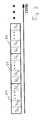
- TDD systems In addition to communicating over different frequency spectrums, spread spectrum TDD systems carry multiple communications over the same spectrum. The multiple signals are distinguished by their respective chip code sequences (codes). Also, to more efficiently use the spread spectrum, TDD systems as illustrated in Figure 2 use repeating frames 34 divided into a number of time slots 36 1 -36 n , , such as fifteen time slots. In such systems, a communication is sent in selected time slots 36 1 -36 n using selected codes. Accordingly, one frame 34 is capable of carrying multiple communications distinguished by both time slot 36 1 -36 n and code. The combination of a single code in a single time slot is referred to as a resource unit. Based on the bandwidth required to support a communication, one or multiple resource units are assigned to that communication.
- TDD systems adaptively control transmission power levels.
- many communications may share the same time slot and spectrum.
- a UE 32 1 or base station 30 1 is receiving a specific communication, all the other communications using the same time slot and spectrum cause interference to the specific communication.
- Increasing the transmission power level of one communication degrades the signal quality of all other communications within that time slot and spectrum.
- reducing the transmission power level too far results in undesirable signal to noise ratios (SNRs) and bit error rates (BERs) at the receivers.
- SNRs signal to noise ratios
- BERs bit error rates
- open loop power control typically a base station 30 1 transmits to a UE 32 1 a reference downlink communication and the transmission power level of that communication.
- the UE 32 1 receives the reference communication and measures its received power level. By subtracting the received power level from the transmission power level, a pathloss for the reference communication is determined.
- the downlink pathloss is added to a desired received power level at the base station 30 1 .
- the UE's transmission power level is set to the determined uplink transmission power level.
- closed loop power control typically the base station 30 1 determines the signal to interference ratio (SIR) of a communication received from the UE 32 1 . The determined SIR is compared to a target SIR (SIR TARGET ). Based on the comparison, the base station 30 1 transmits a power command, b TPC . After receiving the power command, the UE 32 1 increases or decreases its transmission power level based on the received power command.
- SIR signal to interference ratio
- closed loop and open loop power control have disadvantages. Under certain conditions, the performance of closed loop systems degrades. For instance, if communications sent between a UE and a base station are in a highly dynamic environment, such as due to the UE moving, such systems may not be able to adapt fast enough to compensate for the changes.
- the update rate of closed loop power control in TDD is 100 cycles per second which is not sufficient for fast fading channels. Open loop power control is sensitive to uncertainties in the uplink and downlink gain chains and interference levels.
- T UE P BS (n) + L
- P BS (n) P BS (n-1) + b TPC ⁇ TPC
- T UE is the determined transmission power level of the UE 32 1 .
- L is the estimated downlink pathloss.
- P BS (n) is the desired received power level of the base station 30 1 as adjusted by Equation 2.
- b TPC the desired received power level is increased or decreased by ⁇ TPC .
- ⁇ TPC is typically one decibel (dB).
- the power command, b TPC is one, when the SIR of the UE's uplink communication as measured at the base station 30, SIR BS , is less than a target SIR, SIR TARGET . Conversely, the power command is minus one, when SIR BS is larger than SIR TARGET .
- Combined closed loop/open loop power control controls transmission power levels in a spread spectrum time division duplex communication station.
- a first communication station receives communications from a second communication station. The first station transmits power commands based on in part a reception quality of the received communications.
- the first station transmits a second communication having a transmission power level in a first time slot.
- the second station receives the second communication and the power commands.
- a power level of the second communication as received is measured.
- a path loss estimate is determined based on in part the measured received second communication power level and the first communication transmission power level.
- the second station transmits a second communication to the first station in a second time slot.
- the second communication transmission power level is set based on in part the path loss estimate weighted by a factor and the power commands.
- the factor is a function of a time separation of the first and second time slots.
- Combined closed loop/open loop power control will be explained using the flow chart of Figure 3 and the components of two simplified communication stations 50, 52 as shown in Figure 4.
- the communication station having its transmitter's power controlled is referred to as the transmitting station 52 and the communication station receiving power controlled communications is referred to as the receiving station 50.
- the transmitter having its power controlled may be located at a base station 30 1 , UE 32 1 or both. Accordingly, if both uplink and downlink power control are used, the receiving and transmitting station's components are located at both the base station 30 1 and UE 32 1 .
- the receiving station 50 receives various radio frequency signals including communications from the transmitting station 52 using an antenna 56, or alternately, an antenna array.
- the received signals are passed through an isolator 60 to a demodulator 68 to produce a baseband signal.
- the baseband signal is processed, such as by a channel estimation device 96 and a data estimation device 98 , in the time slots and with the appropriate codes assigned to the transmitting station's communication.
- the channel estimation device 96 commonly uses the training sequence component in the baseband signal to provide channel information, such as channel impulse responses.
- the channel information is used by the data estimation device 98 , the interference measurement device 90 , the signal power measurement device 92 and the transmit power calculation device 94 .
- the data estimation device 98 recovers data from the channel by estimating soft symbols using the channel information. Using the soft symbols and channel information, the transmit power calculation device 94 controls the receiving station's transmission power level by controlling the gain of an amplifier 76.
- the signal power measurement device 92 uses either the soft symbols or the channel information, or both, to determine the received signal power of the communication in decibels (dB).
- the interference measurement device 90 determines the interference level in dB, I RS , within the channel, based on either the channel information, or the soft symbols generated by the data estimation device 102 , or both.
- the closed loop power command generator 88 uses the measured communication's received power level and the interference level, I RS , to determine the Signal to Interference Ratio (SIR) of the received communication. Based on a comparison of the determined SIR with a target SIR (SIR TARGET ), a closed loop power command is generated, b TPC , such as a power command bit, b TPC , step 38. Alternately, the power command may be based on any quality measurement of the received signal.
- SIR Signal to Interference Ratio
- the receiving station 50 For use in estimating the path loss between the receiving and transmitting stations 50, 52 and sending data, the receiving station 50 sends a communication to the transmitting station 58, step 40 .
- the communication may be sent on any one of various channels. Typically, in a TDD system, the channels used for estimating path loss are referred to as reference channels, although other channels may be used. If the receiving station 50 is a base station 30 1 , the communication is preferably sent over a downlink common channel or a common control physical channel (CCPCH). Data to be communicated to the transmitting station 52 over the reference channel is referred to as reference channel data.
- CPCH common control physical channel
- the reference data may include, as shown, the interference level, I RS , multiplexed with other reference data, such as the transmission power level of the reference channel, T RS .
- the interference level, I RS , and reference channel power level, T RS may be sent in other channels, such as a signaling channel, step 40.
- the closed loop power control command, b TPC is typically sent in a dedicated channel, dedicated to the communication between the receiving station 50 and transmitting station 52 .
- the reference channel data is generated by a reference channel data generator 86 .
- the reference data is assigned one or multiple resource units based on the communication's bandwidth requirements.
- a spreading and training sequence insertion device 82 spreads the reference channel data and makes the spread reference data time-multiplexed with a training sequence in the appropriate time slots and codes of the assigned resource units. The resulting sequence is referred to as a communication burst.
- the communication burst is subsequently amplified by an amplifier 78 .
- the amplified communication burst may be summed by a sum device 72 with any other communication burst created through devices, such as a data generator 84 , spreading and training sequence insertion device 80 and amplifier 76 .
- the summed communication bursts are modulated by a modulator 64 .
- the modulated signal is passed through an isolator 60 and radiated by an antenna 56 as shown or, alternately, through an antenna array.
- the radiated signal is passed through a wireless radio channel 54 to an antenna 58 of the transmitting station 52 .
- the type of modulation used for the transmitted communication can be any of the those known to those skilled in the art, such as direct phase shift keying (DPSK) or quadrature phase shift keying (QPSK).
- the antenna 58 or, alternately, antenna array of the transmitting station 52 receives various radio frequency signals.
- the received signals are passed through an isolator 62 to a demodulator 66 to produce a baseband signal.
- the baseband signal is processed, such as by a channel estimation device 100 and a data estimation device 102, in the time slots and with the appropriate codes assigned to the communication burst of the receiving station 50 .
- the channel estimation device 100 commonly uses the training sequence component in the baseband signal to provide channel information, such as channel impulse responses.
- the channel information is used by the data estimation device 102 and a power measurement device 110.
- the power level of the processed communication corresponding to the reference channel, R TS is measured by the power measurement device 110 and sent to a pathloss estimation device 112, step 42.
- Both the channel estimation device 100 and the data estimation device 102 are capable of separating the reference channel from all other channels. If an automatic gain control device or amplifier is used for processing the received signals, the measured power level is adjusted to correct for the gain of these devices at either the power measurement device 110 or the pathloss estimation device 112 .
- the power measurement device 110 is a component of the combined closed loop/open loop controller 108. As illustrated in Figure 4, the combined closed loop/open loop power controller 108 consists of the power measurement device 110, pathloss estimation device 112, quality measurement device 114, and transmit power calculation device 116.
- the transmitting station 52 To determine the path loss, L, the transmitting station 52 also requires the communication's transmitted power level, T RS .
- the transmitted power level, T RS may be sent along with the communication's data or in a signaling channel. If the power level, T RS , is sent along with the communication's data, the data estimation device 102 interprets the power level and sends the interpreted power level to the pathloss estimation device 112. If the receiving station 50 is a base station 30 1 , preferably the transmitted power level, T RS , is sent via the broadcast channel (BCH) from the base station 30 1 .
- BCH broadcast channel
- the pathloss estimation device 112 estimates the path loss, L, between the two stations 50, 52, step 42.
- the receiving station 50 may transmit a reference for the transmitted power level. In that case, the pathloss estimation device 112 provides reference levels for the path loss, L.
- the path loss experienced by the transmitted communication may differ from the calculated loss.
- the time slot delay between received and transmitted communications may degrade the performance of an open loop power control system.
- Combined closed loop/open loop power control utilizes both closed loop and open loop power control aspects. If the quality of the path loss measurement is high, the system primarily acts as an open loop system. If the quality of the path loss measurement is low, the system primarily acts as a closed loop system. To combine the two power control aspects, the system weights the open loop aspect based on the quality of the path loss measurement.
- a quality measurement device 114 in a weighted open loop power controller 108 determines the quality of the estimated path loss, step 46 .
- the quality may be determined using the channel information generated by the channel estimation device 100, the soft symbols generated by the data estimation device 102 or other quality measurement techniques.
- the estimated path loss quality is used to weight the path loss estimate by the transmit power calculation device 116. If the power command, b TPC , was sent in the communication's data, the data estimation device 102 interprets the closed loop power command, b TPC . Using the closed loop power command, b TPC , and the weighted path loss, the transmit power calculation device 116 sets the transmit power level of the receiving station 50 , step 48 .
- the transmitting station's power level in decibels, P TS is determined using Equations 4 and 6.
- P TS P 0 + G(n) + ⁇ L
- P 0 is the power level that the receiving station 50 desires to receive the transmitting station's communication in dB.
- P 0 is determined by the desired SIR at the receiving station 50, SIR TARGET , and the interference level, I RS , at the receiving station 50 using Equation 5.
- P 0 SIR TARGET +I RS I RS is either signaled or broadcasted from the receiving station 50 to the transmitting station 52.
- SIR TARGET is known at the transmitting station 52.
- G(n) is the closed loop power control factor.
- Equation 6 is one equation for determining G(n).
- G(n) G(n-1) + b TPC ⁇ TPC
- G(n-1) is the previous closed loop power control factor.
- the power command, b TPC for use in Equation 6 is either +1 or -1.
- One technique for determining the power command, b TPC is Equation 3.
- the power command, b TPC is typically updated at a rate of 100 ms in a TDD system, although other update rates may be used.
- ⁇ TPC is the change in power level.
- the change in power level is typically 1 dB although other values may be used.
- the closed loop factor increases by 1 dB if b TPC is +1 and decreases by 1 dB if b TPC is -1.
- the weighting value, ⁇ is determined by the quality measurement device 114.
- ⁇ is a measure of the quality of the estimated path loss and is, preferably, based on the number of time slots, D, between the time slot of the last path loss estimate and the first time slot of the communication transmitted by the transmitting station 52.
- the value of ⁇ is from zero to one.
- D time difference
- ⁇ is set at a value close to one.
- the time difference is large, the path loss estimate may not be accurate and the closed loop aspect is most likely more accurate. Accordingly, ⁇ is set at a value closer to zero.
- Equation 7 is one equation for determining ⁇ , although others may be used.
- ⁇ 1 - (D - 1)/D max
- D max is the maximum possible delay. A typical value for a frame having fifteen time slots is six. If the delay is D max or greater, ⁇ approaches zero.
- P TS determined by a transmit power calculation device 116 , the combined closed loop/open loop power controller 108 sets the transmit power of the transmitted communication.
- Data to be transmitted in a communication from the transmitting station 52 is produced by a data generator 106.
- the communication data is spread and time-multiplexed with a training sequence by the spreading and training sequence insertion device 104 in the appropriate time slots and codes of the assigned resource units producing a communication burst.
- the spread signal is amplified by the amplifier 74 and modulated by the modulator 70 to radio frequency.
- the combined closed loop/open loop power controller 108 controls the gain of the amplifier 74 to achieve the determined transmit power level, P TS , for the communication.
- the power controlled communication is passed through the isolator 62 and radiated by the antenna 58 .
- Equations 8 and 9 are another preferred combined closed loop/open loop power control algorithm.
- the weighting may be applied to the closed loop factor or both the open and closed loop factors.
- the network operator may desire to use solely open loop or solely closed loop power control.
- the operator may use solely closed loop power control by setting ⁇ to zero.
- Figures 5-10 depict graphs 118-128 illustrating the performance of a combined closed-loop/open-loop power control system. These graphs 118-128 depict the results of simulations comparing the performance of the ARIB proposed system, a closed loop, a combined open loop/closed loop system using Equations 4 and 6 (scheme I) and a combined system using Equations 8 and 9 (scheme II). The simulations were performed at the symbol rate. A spreading factor of sixteen was used for both the uplink and downlink channels.
- the uplink and downlink channels are International Telecommunication Union (ITU) Channel model [ITU-R M.1225, vehicular, type B]. Additive noises were simulated as being independent of white Gaussian noises with unity variance.
- ITU International Telecommunication Union
- the path loss is estimated at the transmitting station 52 which is a UE 32 1 and in particular a mobile station.
- the BCH channel was used for the path loss estimate.
- the path loss was estimated two times per frame at a rate of 200 cycles per second.
- the receiving station 50 which was a base station 30 1 , sent the BCH transmission power level over the BCH.
- RAKE combining was used for both the UE 32 1 and base station 30 1 .
- Antenna diversity combining was used at the base station 30 1 .
- Graphs 118, 122, 126 depict the standard deviation of the received signal to noise ratio (SNR) at the base station 30 1 of the UE's power controlled communication as a function of the time slot delay, D.
- Graphs 120, 124, 128 depict the normalized bias of the received SNR as a function of the delay, D. The normalization was performed with respect to the desired SNR.
- Each point in the graphs 118-128 represents the average of 3000 Monte-Carlo runs.
- Graphs 118, 120 depict the results for an ⁇ set at one.
- scheme I and II outperform closed loop power control.
- closed loop outperforms both scheme I and II which demonstrates the importance of weighting the open loop and closed loop aspects.
- Graphs 126, 128 depict the results for an ⁇ set using Equation 7 with D max equal to six. As shown, schemes I and II outperform both closed loop and the ARIB proposal at all delays, D.
Abstract
Description
- This invention generally relates to spread spectrum time division duplex (TDD) communication systems. More particularly, the present invention relates to a system and method for controlling transmission power within TDD communication systems.
- Figure 1 depicts a wireless spread spectrum time division duplex (TDD) communication system. The system has a plurality'of base stations 301-307. Each base station 301 communicates with user equipments (UEs) 321-323 in its operating area. Communications transmitted from a base station 301 to a UE 321 are referred to as downlink communications and communications transmitted from a UE 321 to a base station 301 are referred to as uplink communications.
- In addition to communicating over different frequency spectrums, spread spectrum TDD systems carry multiple communications over the same spectrum. The multiple signals are distinguished by their respective chip code sequences (codes). Also, to more efficiently use the spread spectrum, TDD systems as illustrated in Figure 2 use repeating frames 34 divided into a number of time slots 361-36n ,, such as fifteen time slots. In such systems, a communication is sent in selected time slots 361-36n using selected codes. Accordingly, one frame 34 is capable of carrying multiple communications distinguished by both time slot 361-36n and code. The combination of a single code in a single time slot is referred to as a resource unit. Based on the bandwidth required to support a communication, one or multiple resource units are assigned to that communication.
- Most TDD systems adaptively control transmission power levels. In a TDD system, many communications may share the same time slot and spectrum. When a UE 321 or base station 301 is receiving a specific communication, all the other communications using the same time slot and spectrum cause interference to the specific communication. Increasing the transmission power level of one communication degrades the signal quality of all other communications within that time slot and spectrum. However, reducing the transmission power level too far results in undesirable signal to noise ratios (SNRs) and bit error rates (BERs) at the receivers. To maintain both the signal quality of communications and low transmission power levels, transmission power control is used.
- One approach to control transmission power levels is open loop power control. In open loop power control, typically a base station 301 transmits to a UE 321 a reference downlink communication and the transmission power level of that communication. The UE 321 receives the reference communication and measures its received power level. By subtracting the received power level from the transmission power level, a pathloss for the reference communication is determined. To determine a transmission power level for the uplink, the downlink pathloss is added to a desired received power level at the base station 301 . The UE's transmission power level is set to the determined uplink transmission power level.
- Another approach to control transmission power level is closed loop power control. In closed loop power control, typically the base station 301 determines the signal to interference ratio (SIR) of a communication received from the UE 321 . The determined SIR is compared to a target SIR (SIRTARGET). Based on the comparison, the base station 301 transmits a power command, bTPC. After receiving the power command, the UE 321 increases or decreases its transmission power level based on the received power command.
- Both closed loop and open loop power control have disadvantages. Under certain conditions, the performance of closed loop systems degrades. For instance, if communications sent between a UE and a base station are in a highly dynamic environment, such as due to the UE moving, such systems may not be able to adapt fast enough to compensate for the changes. The update rate of closed loop power control in TDD is 100 cycles per second which is not sufficient for fast fading channels. Open loop power control is sensitive to uncertainties in the uplink and downlink gain chains and interference levels.
- One approach to combining closed loop and open loop power control was proposed by the Association of Radio Industries and Business (ARIB) and uses Equations 1, 2, and 3.TUE is the determined transmission power level of the UE 321. L is the estimated downlink pathloss. PBS(n) is the desired received power level of the base station 301 as adjusted by Equation 2. For each received power command, bTPC, the desired received power level is increased or decreased by ΔTPC. ΔTPC is typically one decibel (dB). The power command, bTPC, is one, when the SIR of the UE's uplink communication as measured at the base station 30, SIRBS, is less than a target SIR, SIRTARGET. Conversely, the power command is minus one, when SIRBS is larger than SIRTARGET.

- Under certain conditions, the performance of these systems degrades. For instance, if communications sent between a UE 32 and a base station 30 are in a highly dynamic environment, such as due to the UE 32 moving, the path loss estimate for open loop severely degrades the overall system's performance. Accordingly, there is a need for alternate approaches to maintain signal quality and low transmission power levels for all environments and scenarios.
- Combined closed loop/open loop power control controls transmission power levels in a spread spectrum time division duplex communication station. A first communication station receives communications from a second communication station. The first station transmits power commands based on in part a reception quality of the received communications. The first station transmits a second communication having a transmission power level in a first time slot. The second station receives the second communication and the power commands. A power level of the second communication as received is measured. A path loss estimate is determined based on in part the measured received second communication power level and the first communication transmission power level. The second station transmits a second communication to the first station in a second time slot. The second communication transmission power level is set based on in part the path loss estimate weighted by a factor and the power commands. The factor is a function of a time separation of the first and second time slots.
-
- Figure 1 illustrates a prior art TDD system.
- Figure 2 illustrates time slots in repeating frames of a TDD system.
- Figure 3 is a flow chart of combine closed loop/open loop power control.
- Figure 4 is a diagram of components of two communication stations using combined closed loop/open loop power control.
- Figures 5-10 depict graphs of the performance of a closed loop, ARIB's proposal and two (2) schemes of combined closed loop/open loop power control.
-
- The preferred embodiments will be described with reference to the drawing figures where like numerals represent like elements throughout. Combined closed loop/open loop power control will be explained using the flow chart of Figure 3 and the components of two simplified communication stations 50, 52 as shown in Figure 4. For the following discussion, the communication station having its transmitter's power controlled is referred to as the transmitting station 52 and the communication station receiving power controlled communications is referred to as the receiving station 50. Since combined closed loop/open loop power control may be used for uplink, downlink or both types of communications, the transmitter having its power controlled may be located at a base station 301 , UE 321 or both. Accordingly, if both uplink and downlink power control are used, the receiving and transmitting station's components are located at both the base station 301 and UE 321.
- The receiving station 50 receives various radio frequency signals including communications from the transmitting station 52 using an antenna 56, or alternately, an antenna array. The received signals are passed through an isolator 60 to a demodulator 68 to produce a baseband signal. The baseband signal is processed, such as by a channel estimation device 96 and a data estimation device 98, in the time slots and with the appropriate codes assigned to the transmitting station's communication. The channel estimation device 96 commonly uses the training sequence component in the baseband signal to provide channel information, such as channel impulse responses. The channel information is used by the data estimation device 98, the interference measurement device 90, the signal power measurement device 92 and the transmit power calculation device 94. The data estimation device 98 recovers data from the channel by estimating soft symbols using the channel information. Using the soft symbols and channel information, the transmit power calculation device 94 controls the receiving station's transmission power level by controlling the gain of an amplifier 76.
- The signal power measurement device 92 uses either the soft symbols or the channel information, or both, to determine the received signal power of the communication in decibels (dB). The interference measurement device 90 determines the interference level in dB, IRS, within the channel, based on either the channel information, or the soft symbols generated by the data estimation device 102, or both.
- The closed loop power command generator 88 uses the measured communication's received power level and the interference level, IRS, to determine the Signal to Interference Ratio (SIR) of the received communication. Based on a comparison of the determined SIR with a target SIR (SIRTARGET), a closed loop power command is generated, bTPC, such as a power command bit, bTPC, step 38. Alternately, the power command may be based on any quality measurement of the received signal.
- For use in estimating the path loss between the receiving and transmitting stations 50, 52 and sending data, the receiving station 50 sends a communication to the transmitting station 58, step 40. The communication may be sent on any one of various channels. Typically, in a TDD system, the channels used for estimating path loss are referred to as reference channels, although other channels may be used. If the receiving station 50 is a base station 301 , the communication is preferably sent over a downlink common channel or a common control physical channel (CCPCH). Data to be communicated to the transmitting station 52 over the reference channel is referred to as reference channel data. The reference data may include, as shown, the interference level, IRS, multiplexed with other reference data, such as the transmission power level of the reference channel, TRS. The interference level, IRS, and reference channel power level, TRS, may be sent in other channels, such as a signaling channel, step 40. The closed loop power control command, bTPC, is typically sent in a dedicated channel, dedicated to the communication between the receiving station 50 and transmitting station 52.
- The reference channel data is generated by a reference channel data generator 86. The reference data is assigned one or multiple resource units based on the communication's bandwidth requirements. A spreading and training sequence insertion device 82 spreads the reference channel data and makes the spread reference data time-multiplexed with a training sequence in the appropriate time slots and codes of the assigned resource units. The resulting sequence is referred to as a communication burst. The communication burst is subsequently amplified by an amplifier 78. The amplified communication burst may be summed by a sum device 72 with any other communication burst created through devices, such as a data generator 84, spreading and training sequence insertion device 80 and amplifier 76.
- The summed communication bursts are modulated by a modulator 64. The modulated signal is passed through an isolator 60 and radiated by an antenna 56 as shown or, alternately, through an antenna array. The radiated signal is passed through a wireless radio channel 54 to an antenna 58 of the transmitting station 52. The type of modulation used for the transmitted communication can be any of the those known to those skilled in the art, such as direct phase shift keying (DPSK) or quadrature phase shift keying (QPSK).
- The antenna 58 or, alternately, antenna array of the transmitting station 52 receives various radio frequency signals. The received signals are passed through an isolator 62 to a demodulator 66 to produce a baseband signal. The baseband signal is processed, such as by a channel estimation device 100 and a data estimation device 102, in the time slots and with the appropriate codes assigned to the communication burst of the receiving station 50. The channel estimation device 100 commonly uses the training sequence component in the baseband signal to provide channel information, such as channel impulse responses. The channel information is used by the data estimation device 102 and a power measurement device 110.
- The power level of the processed communication corresponding to the reference channel, RTS, is measured by the power measurement device 110 and sent to a pathloss estimation device 112, step 42. Both the channel estimation device 100 and the data estimation device 102 are capable of separating the reference channel from all other channels. If an automatic gain control device or amplifier is used for processing the received signals, the measured power level is adjusted to correct for the gain of these devices at either the power measurement device 110 or the pathloss estimation device 112. The power measurement device 110 is a component of the combined closed loop/open loop controller 108. As illustrated in Figure 4, the combined closed loop/open loop power controller 108 consists of the power measurement device 110, pathloss estimation device 112, quality measurement device 114, and transmit power calculation device 116.
- To determine the path loss, L, the transmitting station 52 also requires the communication's transmitted power level, TRS. The transmitted power level, TRS, may be sent along with the communication's data or in a signaling channel. If the power level, TRS, is sent along with the communication's data, the data estimation device 102 interprets the power level and sends the interpreted power level to the pathloss estimation device 112. If the receiving station 50 is a base station 301 , preferably the transmitted power level, TRS, is sent via the broadcast channel (BCH) from the base station 301 . By subtracting the received communication's power level, RTS in dB, from the sent communication's transmitted power level, TRS in dB, the pathloss estimation device 112 estimates the path loss, L, between the two stations 50, 52, step 42. In certain situations, instead of transmitting the transmitted power level, TRS, the receiving station 50 may transmit a reference for the transmitted power level. In that case, the pathloss estimation device 112 provides reference levels for the path loss, L.
- If a time delay exists between the estimated path loss and the transmitted communication, the path loss experienced by the transmitted communication may differ from the calculated loss. In TDD systems where communications are sent in differing time slots 361-36n, the time slot delay between received and transmitted communications may degrade the performance of an open loop power control system. Combined closed loop/open loop power control utilizes both closed loop and open loop power control aspects. If the quality of the path loss measurement is high, the system primarily acts as an open loop system. If the quality of the path loss measurement is low, the system primarily acts as a closed loop system. To combine the two power control aspects, the system weights the open loop aspect based on the quality of the path loss measurement.
- A quality measurement device 114 in a weighted open loop power controller 108 determines the quality of the estimated path loss, step 46. The quality may be determined using the channel information generated by the channel estimation device 100, the soft symbols generated by the data estimation device 102 or other quality measurement techniques. The estimated path loss quality is used to weight the path loss estimate by the transmit power calculation device 116. If the power command, bTPC, was sent in the communication's data, the data estimation device 102 interprets the closed loop power command, bTPC. Using the closed loop power command, bTPC, and the weighted path loss, the transmit power calculation device 116 sets the transmit power level of the receiving station 50, step 48.
- The following is one of the preferred combined closed loop/open loop power control algorithms. The transmitting station's power level in decibels, PTS, is determined using Equations 4 and 6.
- The weighting value, α, is determined by the quality measurement device 114. α is a measure of the quality of the estimated path loss and is, preferably, based on the number of time slots, D, between the time slot of the last path loss estimate and the first time slot of the communication transmitted by the transmitting station 52. The value of α is from zero to one. Generally, if the time difference, D, between the time slots is small, the recent path loss estimate will be fairly accurate and α is set at a value close to one. By contrast, if the time difference is large, the path loss estimate may not be accurate and the closed loop aspect is most likely more accurate. Accordingly, α is set at a value closer to zero.
- Equation 7 is one equation for determining α, although others may be used.
- Data to be transmitted in a communication from the transmitting station 52 is produced by a data generator 106. The communication data is spread and time-multiplexed with a training sequence by the spreading and training sequence insertion device 104 in the appropriate time slots and codes of the assigned resource units producing a communication burst. The spread signal is amplified by the amplifier 74 and modulated by the modulator 70 to radio frequency.
- The combined closed loop/open loop power controller 108 controls the gain of the amplifier 74 to achieve the determined transmit power level, PTS, for the communication. The power controlled communication is passed through the isolator 62 and radiated by the antenna 58.
- Equations 8 and 9 are another preferred combined closed loop/open loop power control algorithm.
- Although the two above algorithms only weighted the open loop factor, the weighting may be applied to the closed loop factor or both the open and closed loop factors. Under certain conditions, the network operator may desire to use solely open loop or solely closed loop power control. For example, the operator may use solely closed loop power control by setting α to zero.
- Figures 5-10 depict graphs 118-128 illustrating the performance of a combined closed-loop/open-loop power control system. These graphs 118-128 depict the results of simulations comparing the performance of the ARIB proposed system, a closed loop, a combined open loop/closed loop system using Equations 4 and 6 (scheme I) and a combined system using Equations 8 and 9 (scheme II). The simulations were performed at the symbol rate. A spreading factor of sixteen was used for both the uplink and downlink channels. The uplink and downlink channels are International Telecommunication Union (ITU) Channel model [ITU-R M.1225, vehicular, type B]. Additive noises were simulated as being independent of white Gaussian noises with unity variance. The path loss is estimated at the transmitting station 52 which is a UE 321 and in particular a mobile station. The BCH channel was used for the path loss estimate. The path loss was estimated two times per frame at a rate of 200 cycles per second. The receiving station 50, which was a base station 301, sent the BCH transmission power level over the BCH. RAKE combining was used for both the UE 321 and base station 301. Antenna diversity combining was used at the base station 301 .
- Graphs 118, 122, 126 depict the standard deviation of the received signal to noise ratio (SNR) at the base station 301 of the UE's power controlled communication as a function of the time slot delay, D. Graphs 120, 124, 128 depict the normalized bias of the received SNR as a function of the delay, D. The normalization was performed with respect to the desired SNR. Each point in the graphs 118-128 represents the average of 3000 Monte-Carlo runs.
- Graphs 118, 120 depict the results for an α set at one. For low time slot delays (D<4), scheme I and II outperform closed loop power control. For larger delays (D≥4), closed loop outperforms both scheme I and II which demonstrates the importance of weighting the open loop and closed loop aspects.
- Graphs 122,124 depict the results for an α set at 0.5. As shown, for all delays excluding the maximum, schemes I and II outperform closed loop power control. The ARIB proposal only outperforms the others at the lowest delay (D=1).
- Graphs 126, 128 depict the results for an α set using Equation 7 with Dmax equal to six. As shown, schemes I and II outperform both closed loop and the ARIB proposal at all delays, D.
Claims (9)
- A spread spectrum time division duplex user equipment (52), the user equipment (52) using frames with time slots for communication, the user equipment (52) receiving power commands and receiving a first communication having a transmission power level in a first time slot, the user equipment (52) measuring a power level of the first communication as received and determining a pathloss estimate based on in part the measured received first communication level and the first communication transmission power level, the system characterized by the user equipment (52) comprising:means (108) for setting a transmission power level for a second communication in a second time slot from the user equipment (52) based on in part the pathloss estimate weighted by a quality factor adjusted by the power commands, wherein the quality factor decreases as a number of time slots between the first and second time slots increases.
- The user equipment (52) of claim 1 further characterized by comprising means for determining the quality factor, α, of the pathloss estimate based on in part a number of time slots, D, between the first and second time slot.
- The user equipment (52) of claim 2 further characterized by a maximum time slot delay is Dmax and the determined quality factor, α, is determined by
- The user equipment (52) of any preceding claim further characterized in that the setting means (108) sets the transmission power level based on in part a desired received power level, a closed loop factor and an open loop factor, the closed loop factor is based on in part the received power commands and the open loop factor is based on in part the pathloss estimate weighted by the quality factor.
- The user equipment (52) of claim 4 further characterized in that the closed loop factor is updated for each received power command.
- The user equipment (52) of claim 4 or claim 5 further characterized in that the desired received power level is based on in part a target signal to interference ratio and a measured interference level.
- The user equipment (52) of any one of claims 1 to 3 further characterized in that the setting means (108) sets the transmission power level based on in part a desired received power level at the first station (50) and a combined closed loop/open loop factor, the combined closed loop/open loop factor is based on in part the received power commands and the path loss estimate weighted by the quality factor.
- The user equipment (52) of claim 7 further characterized in that the combined factor is updated for each received power command.
- The user equipment (52) of claim 7 or claim 8 further characterized in that the desired received power level is based on in part a target signal to interference ratio and a measured interference level.
Applications Claiming Priority (7)
| Application Number | Priority Date | Filing Date | Title |
|---|---|---|---|
| US12541799P | 1999-03-22 | 1999-03-22 | |
| US125417P | 1999-03-22 | ||
| US13655699P | 1999-05-28 | 1999-05-28 | |
| US13655799P | 1999-05-28 | 1999-05-28 | |
| US136556P | 1999-05-28 | ||
| US136557P | 1999-05-28 | ||
| EP00921419A EP1163737B1 (en) | 1999-03-22 | 2000-03-22 | Combined closed loop/open loop power control in a time division duplex communication system |
Related Parent Applications (1)
| Application Number | Title | Priority Date | Filing Date |
|---|---|---|---|
| EP00921419A Division EP1163737B1 (en) | 1999-03-22 | 2000-03-22 | Combined closed loop/open loop power control in a time division duplex communication system |
Publications (3)
| Publication Number | Publication Date |
|---|---|
| EP1313233A2 true EP1313233A2 (en) | 2003-05-21 |
| EP1313233A3 EP1313233A3 (en) | 2003-09-24 |
| EP1313233B1 EP1313233B1 (en) | 2006-01-11 |
Family
ID=27383242
Family Applications (11)
| Application Number | Title | Priority Date | Filing Date |
|---|---|---|---|
| EP10184382.9A Expired - Lifetime EP2285167B1 (en) | 1999-03-22 | 2000-03-22 | Outer loop/weighted open loop power control in a time division duplex communication system |
| EP00921419A Expired - Lifetime EP1163737B1 (en) | 1999-03-22 | 2000-03-22 | Combined closed loop/open loop power control in a time division duplex communication system |
| EP05104850A Expired - Lifetime EP1578030B1 (en) | 1999-03-22 | 2000-03-22 | Weighted open loop power control in a time division duplex communication system |
| EP08167691A Expired - Lifetime EP2015466B1 (en) | 1999-03-22 | 2000-03-22 | Weighted open loop power control in a time division duplex communication system |
| EP02026085A Expired - Lifetime EP1313233B1 (en) | 1999-03-22 | 2000-03-22 | Combined closed loop/open loop power control in a time division duplex communication system |
| EP05103710A Expired - Lifetime EP1578029B9 (en) | 1999-03-22 | 2000-03-22 | Outer loop/weighted open loop power control in a time division duplex communication system |
| EP00921420A Expired - Lifetime EP1163738B1 (en) | 1999-03-22 | 2000-03-22 | Weighted open loop power control in a time division duplex communication system |
| EP03013811A Expired - Lifetime EP1349294B1 (en) | 1999-03-22 | 2000-03-22 | Weighted open loop power control in a time division duplex communication system |
| EP03019004A Expired - Lifetime EP1367740B1 (en) | 1999-03-22 | 2000-03-22 | Outer loop/weighted open loop power control in a time division duplex communication system |
| EP08166566A Expired - Lifetime EP2009809B1 (en) | 1999-03-22 | 2000-03-22 | Outer loop/weighted open loop power control in a time division duplex communication system |
| EP00916600A Expired - Lifetime EP1163735B1 (en) | 1999-03-22 | 2000-03-22 | Outer loop/weighted open loop power control in a time division duplex communication system |
Family Applications Before (4)
| Application Number | Title | Priority Date | Filing Date |
|---|---|---|---|
| EP10184382.9A Expired - Lifetime EP2285167B1 (en) | 1999-03-22 | 2000-03-22 | Outer loop/weighted open loop power control in a time division duplex communication system |
| EP00921419A Expired - Lifetime EP1163737B1 (en) | 1999-03-22 | 2000-03-22 | Combined closed loop/open loop power control in a time division duplex communication system |
| EP05104850A Expired - Lifetime EP1578030B1 (en) | 1999-03-22 | 2000-03-22 | Weighted open loop power control in a time division duplex communication system |
| EP08167691A Expired - Lifetime EP2015466B1 (en) | 1999-03-22 | 2000-03-22 | Weighted open loop power control in a time division duplex communication system |
Family Applications After (6)
| Application Number | Title | Priority Date | Filing Date |
|---|---|---|---|
| EP05103710A Expired - Lifetime EP1578029B9 (en) | 1999-03-22 | 2000-03-22 | Outer loop/weighted open loop power control in a time division duplex communication system |
| EP00921420A Expired - Lifetime EP1163738B1 (en) | 1999-03-22 | 2000-03-22 | Weighted open loop power control in a time division duplex communication system |
| EP03013811A Expired - Lifetime EP1349294B1 (en) | 1999-03-22 | 2000-03-22 | Weighted open loop power control in a time division duplex communication system |
| EP03019004A Expired - Lifetime EP1367740B1 (en) | 1999-03-22 | 2000-03-22 | Outer loop/weighted open loop power control in a time division duplex communication system |
| EP08166566A Expired - Lifetime EP2009809B1 (en) | 1999-03-22 | 2000-03-22 | Outer loop/weighted open loop power control in a time division duplex communication system |
| EP00916600A Expired - Lifetime EP1163735B1 (en) | 1999-03-22 | 2000-03-22 | Outer loop/weighted open loop power control in a time division duplex communication system |
Country Status (19)
| Country | Link |
|---|---|
| EP (11) | EP2285167B1 (en) |
| JP (3) | JP3621888B2 (en) |
| KR (2) | KR100401219B1 (en) |
| CN (12) | CN1878017B (en) |
| AT (10) | ATE303019T1 (en) |
| AU (3) | AU4174300A (en) |
| BR (2) | BR0009130A (en) |
| CA (5) | CA2367353C (en) |
| DE (11) | DE60006945T2 (en) |
| DK (7) | DK1578030T3 (en) |
| ES (9) | ES2203455T3 (en) |
| HK (11) | HK1041576B (en) |
| ID (2) | ID30470A (en) |
| IL (7) | IL145026A0 (en) |
| MY (2) | MY128631A (en) |
| NO (4) | NO323601B1 (en) |
| SG (9) | SG108845A1 (en) |
| TW (3) | TW459452B (en) |
| WO (3) | WO2000057574A1 (en) |
Families Citing this family (57)
| Publication number | Priority date | Publication date | Assignee | Title |
|---|---|---|---|---|
| US6748234B1 (en) * | 2000-11-21 | 2004-06-08 | Qualcomm Incorporated | Method and apparatus for power control in a wireless communication system |
| JP3440076B2 (en) * | 2000-11-29 | 2003-08-25 | 松下電器産業株式会社 | Wireless infrastructure equipment |
| US6978151B2 (en) | 2001-05-10 | 2005-12-20 | Koninklijke Philips Electronics N.V. | Updating path loss estimation for power control and link adaptation in IEEE 802.11h WLAN |
| WO2003032502A2 (en) * | 2001-10-09 | 2003-04-17 | Interdigital Technology Corporation | Pathloss aided closed loop power control |
| GB2381417A (en) | 2001-10-24 | 2003-04-30 | Ipwireless Inc | Transmission power control based on path loss |
| ATE473558T1 (en) * | 2001-12-03 | 2010-07-15 | Ericsson Telefon Ab L M | METHOD FOR ROUTE ADJUSTMENT AND TRANSMIT POWER CONTROL |
| US7133689B2 (en) * | 2002-09-12 | 2006-11-07 | Interdigital Technology Corporation | Method and system for adjusting downlink outer loop power to control target SIR |
| US7372898B2 (en) * | 2002-12-11 | 2008-05-13 | Interdigital Technology Corporation | Path loss measurements in wireless communications |
| CN100568769C (en) * | 2003-06-16 | 2009-12-09 | 株式会社Ntt都科摩 | Control device and wireless control method |
| CN1322767C (en) * | 2003-07-29 | 2007-06-20 | 大唐移动通信设备有限公司 | Power control method for mobile communication system |
| US7403780B2 (en) | 2004-02-19 | 2008-07-22 | Rockwell Collins, Inc. | Hybrid open/closed loop filtering for link quality estimation |
| WO2005083953A1 (en) * | 2004-02-19 | 2005-09-09 | Rockwell Collins Inc. | Link adaption for mobile ad hoc and mesh networks |
| US7835384B2 (en) | 2004-07-01 | 2010-11-16 | Telefonaktiebolaget Lm Ericsson | Power control in a communication network and method |
| US7907910B2 (en) | 2004-08-02 | 2011-03-15 | Intel Corporation | Method and apparatus to vary power level of training signal |
| JP2006050498A (en) | 2004-08-09 | 2006-02-16 | Nec Corp | Mobile communication terminal device, mobile communication method, and program thereof |
| US8897828B2 (en) | 2004-08-12 | 2014-11-25 | Intellectual Ventures Holding 81 Llc | Power control in a wireless communication system |
| KR100725773B1 (en) * | 2004-08-20 | 2007-06-08 | 삼성전자주식회사 | Apparatus and method for adaptively changing the uplink power control scheme depending on the status of mobile station in a wireless mobile communication system using time division duplexing scheme |
| KR100946099B1 (en) * | 2005-03-15 | 2010-03-10 | 콸콤 인코포레이티드 | Interference information from multiple sectors for power control |
| CN101180804B (en) * | 2005-04-20 | 2011-06-08 | 三菱电机株式会社 | Communication quality determining method, mobile station, base station and communication system |
| WO2007002032A2 (en) * | 2005-06-20 | 2007-01-04 | Texas Instruments Incorporated | Slow uplink power control |
| CN100385822C (en) * | 2005-11-25 | 2008-04-30 | 凯明信息科技股份有限公司 | Discontinuous transmitting state power control method in TD-SCDMA system |
| KR20070059666A (en) * | 2005-12-07 | 2007-06-12 | 삼성전자주식회사 | Apparatus and method for power controlling of time division duplex telecommunication system |
| CN1988407B (en) * | 2005-12-22 | 2010-07-07 | 大唐移动通信设备有限公司 | Open ring power control method for base station and its physical random cut-in channel |
| CN101064538B (en) * | 2006-04-30 | 2011-04-20 | 中兴通讯股份有限公司 | Power control method for time-division synchronous CDMA communication system |
| CN101119145B (en) * | 2006-08-03 | 2010-10-27 | 普天信息技术研究院 | Auxiliary frequency point opened loop power control method in time division synchronous CDMA system |
| US8195097B2 (en) * | 2006-09-08 | 2012-06-05 | Qualcomm Incorporated | Serving sector interference broadcast and corresponding RL traffic power control |
| CN107105489A (en) * | 2006-10-03 | 2017-08-29 | 交互数字技术公司 | Combined type open/close for E UTRA interference mitigation(Based on CQI)Up-link transmission power is controlled |
| KR101163280B1 (en) | 2006-10-03 | 2012-07-10 | 인터디지탈 테크날러지 코포레이션 | Combined open loop/closed loop cqi-based uplink transmit power control with interference mitigation for e-utra |
| TWI536761B (en) * | 2007-03-07 | 2016-06-01 | 內數位科技公司 | Combined open loop/closed loop method for controlling uplink power of a mobile station, a wtru and an enodeb |
| CN101296003B (en) * | 2007-04-25 | 2012-11-28 | 中兴通讯股份有限公司 | Power control method and system for reinforced uplink transmitting scheduling information |
| CN101340215B (en) * | 2007-07-04 | 2012-07-25 | 鼎桥通信技术有限公司 | Method and device for determining transmitting power of special burst sub-frame |
| CN101345906B (en) * | 2007-07-13 | 2012-03-14 | 电信科学技术研究院 | Wireless resource allocation method and apparatus of high speed grouping access system |
| CN101394206B (en) * | 2007-09-17 | 2012-11-28 | 中兴通讯股份有限公司 | Method for downlink power control synchronous signaling transmission |
| EP2045930B1 (en) * | 2007-09-28 | 2010-07-28 | NTT DoCoMo, Inc. | Decentralized C/I power control for TDD |
| US8958460B2 (en) | 2008-03-18 | 2015-02-17 | On-Ramp Wireless, Inc. | Forward error correction media access control system |
| CN101568173B (en) * | 2008-04-21 | 2012-02-01 | 电信科学技术研究院 | Method, device and system for controlling power |
| JP5307895B2 (en) * | 2008-09-03 | 2013-10-02 | トムソン ライセンシング | Method and apparatus for performing transmission power control in a wireless network |
| US8363699B2 (en) | 2009-03-20 | 2013-01-29 | On-Ramp Wireless, Inc. | Random timing offset determination |
| US7702290B1 (en) * | 2009-04-08 | 2010-04-20 | On-Ramp Wirless, Inc. | Dynamic energy control |
| CN101577958B (en) * | 2009-06-02 | 2010-11-03 | 北京天碁科技有限公司 | System and method for testing performance of closed loop power control algorithm |
| US8311055B2 (en) | 2009-12-08 | 2012-11-13 | Futurewei Technologies, Inc. | System and method for scheduling users on a wireless network |
| US9031599B2 (en) | 2009-12-08 | 2015-05-12 | Futurewei Technologies, Inc. | System and method for power control |
| US8515474B2 (en) | 2010-01-20 | 2013-08-20 | Futurewei Technologies, Inc. | System and method for scheduling users on a wireless network |
| US8437794B2 (en) * | 2010-01-28 | 2013-05-07 | Alcatel Lucent | Methods of determining uplink target signal-to-interfence-and-noise ratios and systems thereof |
| US20110263212A1 (en) * | 2010-04-26 | 2011-10-27 | Chih-Hao Yeh | Wireless device and controlling method of wireless device |
| TWI488527B (en) * | 2010-05-05 | 2015-06-11 | Zyxel Communications Corp | Communication method utilized in time division multiple access system, related mobile device and base station |
| WO2013109888A1 (en) | 2012-01-19 | 2013-07-25 | Futurewei Technologies, Inc. | Systems and method for uplink resource allocation |
| US9630128B2 (en) | 2012-07-04 | 2017-04-25 | Aisin Seiki Kabushiki Kaisha | Oil separator |
| CN104244390A (en) * | 2013-06-17 | 2014-12-24 | 中兴通讯股份有限公司 | Open loop joint power control method and device of wireless body area network |
| US20170141860A1 (en) * | 2014-06-25 | 2017-05-18 | Nec Corporation | Wireless relay system, wireless relay method, storage medium in which wireless relay program is stored, and wireless relay station |
| CN108235420B (en) * | 2016-12-12 | 2021-06-25 | 上海朗帛通信技术有限公司 | Method and device for power adjustment in UE and base station |
| CN106973431B (en) * | 2017-02-14 | 2021-03-05 | 深圳市金立通信设备有限公司 | Transmission power adjusting method and terminal |
| CN110115068B (en) * | 2017-04-21 | 2023-05-02 | 深圳市大疆创新科技有限公司 | Adaptive transmit power control for wireless communication systems |
| US10505836B2 (en) * | 2017-04-21 | 2019-12-10 | Mediatek Inc. | Symmetric route establishment with bidirectional links for wireless mesh networks |
| US11589305B2 (en) | 2018-03-12 | 2023-02-21 | Apple Inc. | Scheduling profile for UE power savings |
| CN111542104A (en) * | 2020-04-20 | 2020-08-14 | 东南大学 | Closed-loop power control method applied to communication between devices |
| CN112910430B (en) * | 2021-01-15 | 2024-03-12 | 北京格润海泰科技有限公司 | Control method and device for automatically adjusting power gain of radio frequency signal |
Citations (5)
| Publication number | Priority date | Publication date | Assignee | Title |
|---|---|---|---|---|
| EP0682419A2 (en) * | 1994-05-12 | 1995-11-15 | Ntt Mobile Communications Network Inc. | Transmission power control for mobile radio using open and closed loop |
| US5542111A (en) * | 1993-03-19 | 1996-07-30 | Siemens Aktiengesellschaft | Method for transmission power control of a mobile station |
| WO1997049197A1 (en) * | 1996-06-17 | 1997-12-24 | Nokia Mobile Phones Limited | Control of transmission power in wireless packet data transfer |
| WO1998045962A1 (en) * | 1997-04-04 | 1998-10-15 | Ericsson, Inc. | Power control for a mobile terminal in a satellite communication system |
| US5859838A (en) * | 1996-07-30 | 1999-01-12 | Qualcomm Incorporated | Load monitoring and management in a CDMA wireless communication system |
Family Cites Families (21)
| Publication number | Priority date | Publication date | Assignee | Title |
|---|---|---|---|---|
| US4868795A (en) * | 1985-08-05 | 1989-09-19 | Terra Marine Engineering, Inc. | Power leveling telemetry system |
| US4947459A (en) * | 1988-11-25 | 1990-08-07 | Honeywell, Inc. | Fiber optic link noise measurement and optimization system |
| US5056109A (en) | 1989-11-07 | 1991-10-08 | Qualcomm, Inc. | Method and apparatus for controlling transmission power in a cdma cellular mobile telephone system |
| SE467332B (en) * | 1990-06-21 | 1992-06-29 | Ericsson Telefon Ab L M | PROCEDURE FOR POWER CONTROL IN A DIGITAL MOBILE PHONE SYSTEM |
| EP0569688A1 (en) * | 1992-04-29 | 1993-11-18 | Hagenuk Telecom GmbH | Method and apparatus for fading compensation for TDMA-receivers |
| US5590173A (en) * | 1992-08-05 | 1996-12-31 | Beasley; Andrew S. | Delay insensitive base station-to-handset interface for radio telephone systems |
| NZ255617A (en) * | 1992-09-04 | 1996-11-26 | Ericsson Telefon Ab L M | Tdma digital radio: measuring path loss and setting transmission power accordingly |
| US5333175A (en) * | 1993-01-28 | 1994-07-26 | Bell Communications Research, Inc. | Method and apparatus for dynamic power control in TDMA portable radio systems |
| FI96554C (en) * | 1993-02-05 | 1996-07-10 | Nokia Mobile Phones Ltd | Time multiplexed cellular radio telephone system and radio telephone for it |
| JPH0774727A (en) * | 1993-09-06 | 1995-03-17 | Matsushita Electric Ind Co Ltd | Transmission power control system for spread spectrum communication |
| US6088590A (en) * | 1993-11-01 | 2000-07-11 | Omnipoint Corporation | Method and system for mobile controlled handoff and link maintenance in spread spectrum communication |
| JP3386586B2 (en) * | 1994-08-18 | 2003-03-17 | 松下電器産業株式会社 | Mobile communication method |
| WO1996031009A1 (en) * | 1995-03-27 | 1996-10-03 | Celsat America, Inc. | Cellular communications power control system |
| US5629934A (en) * | 1995-06-30 | 1997-05-13 | Motorola, Inc. | Power control for CDMA communication systems |
| ZA965340B (en) * | 1995-06-30 | 1997-01-27 | Interdigital Tech Corp | Code division multiple access (cdma) communication system |
| WO1997008847A1 (en) * | 1995-08-31 | 1997-03-06 | Nokia Telecommunications Oy | Method and device for controlling transmission power of a radio transmitter in a cellular communication system |
| DE69729784T2 (en) * | 1996-06-27 | 2005-06-23 | Ntt Docomo, Inc. | ARRANGEMENT FOR TRANSMISSION CONTROL |
| KR980007105A (en) * | 1996-06-28 | 1998-03-30 | 김광호 | Method for controlling transmission power of mobile station |
| JP3240262B2 (en) * | 1996-07-25 | 2001-12-17 | 株式会社日立国際電気 | Adaptive modulation transmission method and system |
| NZ502698A (en) * | 1997-08-01 | 2003-03-28 | Salbu Res & Dev Pty Ltd | Power adaption in a multi-station network |
| JPH11275035A (en) * | 1998-01-26 | 1999-10-08 | Matsushita Electric Ind Co Ltd | Mobile station communication equipment, base station communication equipment, and radio communication system |
-
2000
- 2000-03-21 MY MYPI20001120A patent/MY128631A/en unknown
- 2000-03-21 MY MYPI20001119A patent/MY129851A/en unknown
- 2000-03-22 ID IDW00200101922A patent/ID30470A/en unknown
- 2000-03-22 CN CN200610095731.4A patent/CN1878017B/en not_active Expired - Fee Related
- 2000-03-22 TW TW089105247A patent/TW459452B/en not_active IP Right Cessation
- 2000-03-22 EP EP10184382.9A patent/EP2285167B1/en not_active Expired - Lifetime
- 2000-03-22 EP EP00921419A patent/EP1163737B1/en not_active Expired - Lifetime
- 2000-03-22 WO PCT/US2000/007476 patent/WO2000057574A1/en active IP Right Grant
- 2000-03-22 IL IL14502600A patent/IL145026A0/en active IP Right Grant
- 2000-03-22 CN CNB008049645A patent/CN1148014C/en not_active Expired - Fee Related
- 2000-03-22 ES ES00921420T patent/ES2203455T3/en not_active Expired - Lifetime
- 2000-03-22 ES ES02026085T patent/ES2209677T1/en active Pending
- 2000-03-22 SG SG200202255A patent/SG108845A1/en unknown
- 2000-03-22 DE DE60006945T patent/DE60006945T2/en not_active Expired - Lifetime
- 2000-03-22 DE DE1163735T patent/DE1163735T1/en active Pending
- 2000-03-22 ES ES05104850T patent/ES2318422T3/en not_active Expired - Lifetime
- 2000-03-22 SG SG200202124A patent/SG108842A1/en unknown
- 2000-03-22 AU AU41743/00A patent/AU4174300A/en not_active Abandoned
- 2000-03-22 CN CNB2004100078619A patent/CN1322683C/en not_active Expired - Fee Related
- 2000-03-22 SG SG200202122A patent/SG112830A1/en unknown
- 2000-03-22 DE DE60002688T patent/DE60002688T2/en not_active Expired - Lifetime
- 2000-03-22 ES ES03013811T patent/ES2246444T3/en not_active Expired - Lifetime
- 2000-03-22 BR BR0009130-8A patent/BR0009130A/en not_active Application Discontinuation
- 2000-03-22 AU AU37681/00A patent/AU756316B2/en not_active Ceased
- 2000-03-22 AT AT03019004T patent/ATE303019T1/en not_active IP Right Cessation
- 2000-03-22 SG SG200202121A patent/SG109964A1/en unknown
- 2000-03-22 CN CNB200410059280XA patent/CN100362768C/en not_active Expired - Fee Related
- 2000-03-22 CA CA002367353A patent/CA2367353C/en not_active Expired - Fee Related
- 2000-03-22 DK DK05104850T patent/DK1578030T3/en active
- 2000-03-22 AT AT00916600T patent/ATE255790T1/en not_active IP Right Cessation
- 2000-03-22 ES ES00916600T patent/ES2211522T3/en not_active Expired - Lifetime
- 2000-03-22 TW TW089105248A patent/TW490940B/en not_active IP Right Cessation
- 2000-03-22 AT AT02026085T patent/ATE315851T1/en not_active IP Right Cessation
- 2000-03-22 CN CN2006100958957A patent/CN1956345B/en not_active Expired - Fee Related
- 2000-03-22 DE DE1163738T patent/DE1163738T1/en active Pending
- 2000-03-22 SG SG200202258A patent/SG115465A1/en unknown
- 2000-03-22 SG SG200706366-2A patent/SG157965A1/en unknown
- 2000-03-22 JP JP2000607352A patent/JP3621888B2/en not_active Expired - Fee Related
- 2000-03-22 KR KR10-2001-7011973A patent/KR100401219B1/en not_active IP Right Cessation
- 2000-03-22 EP EP05104850A patent/EP1578030B1/en not_active Expired - Lifetime
- 2000-03-22 WO PCT/US2000/007556 patent/WO2000057576A1/en active Application Filing
- 2000-03-22 CN CNB008052417A patent/CN1157862C/en not_active Expired - Fee Related
- 2000-03-22 AT AT05103710T patent/ATE412279T1/en not_active IP Right Cessation
- 2000-03-22 SG SG200202257A patent/SG115464A1/en unknown
- 2000-03-22 SG SG200202256A patent/SG108846A1/en unknown
- 2000-03-22 ES ES05103710T patent/ES2314566T3/en not_active Expired - Lifetime
- 2000-03-22 DK DK03019004T patent/DK1367740T3/en active
- 2000-03-22 DK DK00916600T patent/DK1163735T3/en active
- 2000-03-22 ES ES03019004T patent/ES2247465T3/en not_active Expired - Lifetime
- 2000-03-22 CN CN2006100958942A patent/CN1953346B/en not_active Expired - Fee Related
- 2000-03-22 ID IDW00200101923A patent/ID30329A/en unknown
- 2000-03-22 AU AU41744/00A patent/AU761541B2/en not_active Ceased
- 2000-03-22 DE DE60041011T patent/DE60041011D1/en not_active Expired - Lifetime
- 2000-03-22 EP EP08167691A patent/EP2015466B1/en not_active Expired - Lifetime
- 2000-03-22 KR KR10-2001-7011974A patent/KR100401217B1/en not_active IP Right Cessation
- 2000-03-22 CN CNB2004100431028A patent/CN100449957C/en not_active Expired - Fee Related
- 2000-03-22 CA CA2491179A patent/CA2491179C/en not_active Expired - Fee Related
- 2000-03-22 CN CN2006100958938A patent/CN1956344B/en not_active Expired - Fee Related
- 2000-03-22 ES ES10184382.9T patent/ES2634327T3/en not_active Expired - Lifetime
- 2000-03-22 IL IL14491300A patent/IL144913A0/en active IP Right Grant
- 2000-03-22 DK DK03013811T patent/DK1349294T3/en active
- 2000-03-22 CA CA002367363A patent/CA2367363C/en not_active Expired - Fee Related
- 2000-03-22 AT AT05104850T patent/ATE416519T1/en not_active IP Right Cessation
- 2000-03-22 AT AT00921420T patent/ATE248467T1/en not_active IP Right Cessation
- 2000-03-22 ES ES00921419T patent/ES2199161T3/en not_active Expired - Lifetime
- 2000-03-22 CN CN200610095730XA patent/CN101094017B/en not_active Expired - Fee Related
- 2000-03-22 SG SG200202123A patent/SG109965A1/en unknown
- 2000-03-22 CA CA2700656A patent/CA2700656C/en not_active Expired - Fee Related
- 2000-03-22 AT AT08166566T patent/ATE546026T1/en active
- 2000-03-22 DE DE60023193T patent/DE60023193T2/en not_active Expired - Lifetime
- 2000-03-22 JP JP2000607350A patent/JP3621886B2/en not_active Expired - Fee Related
- 2000-03-22 EP EP02026085A patent/EP1313233B1/en not_active Expired - Lifetime
- 2000-03-22 TW TW089105245A patent/TW498645B/en not_active IP Right Cessation
- 2000-03-22 BR BR0009233-9A patent/BR0009233A/en not_active Application Discontinuation
- 2000-03-22 EP EP05103710A patent/EP1578029B9/en not_active Expired - Lifetime
- 2000-03-22 DE DE60025540T patent/DE60025540D1/en not_active Expired - Lifetime
- 2000-03-22 EP EP00921420A patent/EP1163738B1/en not_active Expired - Lifetime
- 2000-03-22 CA CA2494725A patent/CA2494725C/en not_active Expired - Fee Related
- 2000-03-22 EP EP03013811A patent/EP1349294B1/en not_active Expired - Lifetime
- 2000-03-22 DE DE60040624T patent/DE60040624D1/en not_active Expired - Lifetime
- 2000-03-22 DK DK00921419T patent/DK1163737T3/en active
- 2000-03-22 JP JP2000607351A patent/JP3621887B2/en not_active Expired - Fee Related
- 2000-03-22 EP EP03019004A patent/EP1367740B1/en not_active Expired - Lifetime
- 2000-03-22 DK DK05103710T patent/DK1578029T3/en active
- 2000-03-22 WO PCT/US2000/007477 patent/WO2000057575A1/en active Search and Examination
- 2000-03-22 DE DE60022236T patent/DE60022236T2/en not_active Expired - Lifetime
- 2000-03-22 CN CNB008052409A patent/CN1161891C/en not_active Expired - Fee Related
- 2000-03-22 DK DK00921420T patent/DK1163738T3/en active
- 2000-03-22 EP EP08166566A patent/EP2009809B1/en not_active Expired - Lifetime
- 2000-03-22 AT AT08167691T patent/ATE555629T1/en active
- 2000-03-22 DE DE60004800T patent/DE60004800T2/en not_active Expired - Lifetime
- 2000-03-22 DE DE0001313233T patent/DE02026085T1/en active Pending
- 2000-03-22 AT AT00921419T patent/ATE240615T1/en not_active IP Right Cessation
- 2000-03-22 CN CN200610095732.9A patent/CN101094018B/en not_active Expired - Fee Related
- 2000-03-22 AT AT03013811T patent/ATE306752T1/en not_active IP Right Cessation
- 2000-03-22 EP EP00916600A patent/EP1163735B1/en not_active Expired - Lifetime
-
2001
- 2001-08-15 IL IL144913A patent/IL144913A/en not_active IP Right Cessation
- 2001-08-21 IL IL145026A patent/IL145026A/en not_active IP Right Cessation
- 2001-09-18 NO NO20014538A patent/NO323601B1/en not_active IP Right Cessation
- 2001-09-20 NO NO20014571A patent/NO324439B1/en not_active IP Right Cessation
- 2001-09-20 NO NO20014572A patent/NO323998B1/en not_active IP Right Cessation
-
2002
- 2002-04-29 HK HK02103191.9A patent/HK1041576B/en not_active IP Right Cessation
- 2002-04-29 HK HK02103190.0A patent/HK1041575B/en not_active IP Right Cessation
- 2002-05-02 HK HK02103323.0A patent/HK1042790B/en not_active IP Right Cessation
-
2003
- 2003-10-15 HK HK03107483A patent/HK1059344A1/en not_active IP Right Cessation
-
2004
- 2004-03-31 HK HK06103447.7A patent/HK1085857A1/en not_active IP Right Cessation
- 2004-03-31 HK HK04102373A patent/HK1061476A1/en not_active IP Right Cessation
- 2004-05-28 HK HK06103444.0A patent/HK1085856A1/en not_active IP Right Cessation
- 2004-05-28 HK HK04103860A patent/HK1062505A1/en not_active IP Right Cessation
-
2006
- 2006-07-16 IL IL176873A patent/IL176873A/en not_active IP Right Cessation
- 2006-08-02 IL IL177241A patent/IL177241A0/en not_active IP Right Cessation
-
2007
- 2007-07-18 NO NO20073727A patent/NO325301B1/en not_active IP Right Cessation
- 2007-10-18 HK HK07111331.8A patent/HK1109252A1/en not_active IP Right Cessation
- 2007-10-25 HK HK07111541.4A patent/HK1106346A1/en not_active IP Right Cessation
-
2008
- 2008-06-26 HK HK08107118.4A patent/HK1117284A1/en not_active IP Right Cessation
-
2009
- 2009-07-26 IL IL200072A patent/IL200072A/en not_active IP Right Cessation
Patent Citations (5)
| Publication number | Priority date | Publication date | Assignee | Title |
|---|---|---|---|---|
| US5542111A (en) * | 1993-03-19 | 1996-07-30 | Siemens Aktiengesellschaft | Method for transmission power control of a mobile station |
| EP0682419A2 (en) * | 1994-05-12 | 1995-11-15 | Ntt Mobile Communications Network Inc. | Transmission power control for mobile radio using open and closed loop |
| WO1997049197A1 (en) * | 1996-06-17 | 1997-12-24 | Nokia Mobile Phones Limited | Control of transmission power in wireless packet data transfer |
| US5859838A (en) * | 1996-07-30 | 1999-01-12 | Qualcomm Incorporated | Load monitoring and management in a CDMA wireless communication system |
| WO1998045962A1 (en) * | 1997-04-04 | 1998-10-15 | Ericsson, Inc. | Power control for a mobile terminal in a satellite communication system |
Also Published As
Similar Documents
| Publication | Publication Date | Title |
|---|---|---|
| EP1163737B1 (en) | Combined closed loop/open loop power control in a time division duplex communication system | |
| US6728292B2 (en) | Combined closed loop/open loop power control in a time division duplex communication system | |
| US6597723B1 (en) | Weighted open loop power control in a time division duplex communication system |
Legal Events
| Date | Code | Title | Description |
|---|---|---|---|
| PUAI | Public reference made under article 153(3) epc to a published international application that has entered the european phase |
Free format text: ORIGINAL CODE: 0009012 |
|
| AC | Divisional application: reference to earlier application |
Ref document number: 1163737 Country of ref document: EP Kind code of ref document: P |
|
| AK | Designated contracting states |
Designated state(s): AT BE CH CY DE DK ES FI FR GB GR IE IT LI LU MC NL PT SE |
|
| PUAL | Search report despatched |
Free format text: ORIGINAL CODE: 0009013 |
|
| AK | Designated contracting states |
Kind code of ref document: A3 Designated state(s): AT BE CH CY DE DK ES FI FR GB GR IE IT LI LU MC NL PT SE |
|
| 17P | Request for examination filed |
Effective date: 20031103 |
|
| REG | Reference to a national code |
Ref country code: SE Ref legal event code: TRCL |
|
| EL | Fr: translation of claims filed | ||
| TCNL | Nl: translation of patent claims filed | ||
| DET | De: translation of patent claims | ||
| AKX | Designation fees paid |
Designated state(s): AT BE CH CY DE DK ES FI FR GB GR IE IT LI LU MC NL PT SE |
|
| REG | Reference to a national code |
Ref country code: HK Ref legal event code: DE Ref document number: 1059344 Country of ref document: HK |
|
| 17Q | First examination report despatched |
Effective date: 20040805 |
|
| GRAP | Despatch of communication of intention to grant a patent |
Free format text: ORIGINAL CODE: EPIDOSNIGR1 |
|
| GRAS | Grant fee paid |
Free format text: ORIGINAL CODE: EPIDOSNIGR3 |
|
| GRAA | (expected) grant |
Free format text: ORIGINAL CODE: 0009210 |
|
| AC | Divisional application: reference to earlier application |
Ref document number: 1163737 Country of ref document: EP Kind code of ref document: P |
|
| AK | Designated contracting states |
Kind code of ref document: B1 Designated state(s): AT BE CH CY DE DK ES FI FR GB GR IE IT LI LU MC NL PT SE |
|
| PG25 | Lapsed in a contracting state [announced via postgrant information from national office to epo] |
Ref country code: IT Free format text: LAPSE BECAUSE OF FAILURE TO SUBMIT A TRANSLATION OF THE DESCRIPTION OR TO PAY THE FEE WITHIN THE PRESCRIBED TIME-LIMIT;WARNING: LAPSES OF ITALIAN PATENTS WITH EFFECTIVE DATE BEFORE 2007 MAY HAVE OCCURRED AT ANY TIME BEFORE 2007. THE CORRECT EFFECTIVE DATE MAY BE DIFFERENT FROM THE ONE RECORDED. Effective date: 20060111 Ref country code: AT Free format text: LAPSE BECAUSE OF FAILURE TO SUBMIT A TRANSLATION OF THE DESCRIPTION OR TO PAY THE FEE WITHIN THE PRESCRIBED TIME-LIMIT Effective date: 20060111 Ref country code: LI Free format text: LAPSE BECAUSE OF FAILURE TO SUBMIT A TRANSLATION OF THE DESCRIPTION OR TO PAY THE FEE WITHIN THE PRESCRIBED TIME-LIMIT Effective date: 20060111 Ref country code: FI Free format text: LAPSE BECAUSE OF FAILURE TO SUBMIT A TRANSLATION OF THE DESCRIPTION OR TO PAY THE FEE WITHIN THE PRESCRIBED TIME-LIMIT Effective date: 20060111 Ref country code: BE Free format text: LAPSE BECAUSE OF FAILURE TO SUBMIT A TRANSLATION OF THE DESCRIPTION OR TO PAY THE FEE WITHIN THE PRESCRIBED TIME-LIMIT Effective date: 20060111 Ref country code: NL Free format text: LAPSE BECAUSE OF FAILURE TO SUBMIT A TRANSLATION OF THE DESCRIPTION OR TO PAY THE FEE WITHIN THE PRESCRIBED TIME-LIMIT Effective date: 20060111 Ref country code: CH Free format text: LAPSE BECAUSE OF FAILURE TO SUBMIT A TRANSLATION OF THE DESCRIPTION OR TO PAY THE FEE WITHIN THE PRESCRIBED TIME-LIMIT Effective date: 20060111 |
|
| RIN1 | Information on inventor provided before grant (corrected) |
Inventor name: SHIN, SUNG-HYUK Inventor name: ZEIRA, ARIELA Inventor name: OZLUTURK, FAITH M. |
|
| REG | Reference to a national code |
Ref country code: CH Ref legal event code: EP |
|
| REG | Reference to a national code |
Ref country code: IE Ref legal event code: FG4D |
|
| PG25 | Lapsed in a contracting state [announced via postgrant information from national office to epo] |
Ref country code: IE Free format text: LAPSE BECAUSE OF NON-PAYMENT OF DUE FEES Effective date: 20060322 |
|
| PG25 | Lapsed in a contracting state [announced via postgrant information from national office to epo] |
Ref country code: MC Free format text: LAPSE BECAUSE OF NON-PAYMENT OF DUE FEES Effective date: 20060331 Ref country code: LU Free format text: LAPSE BECAUSE OF NON-PAYMENT OF DUE FEES Effective date: 20060331 |
|
| REF | Corresponds to: |
Ref document number: 60025540 Country of ref document: DE Date of ref document: 20060406 Kind code of ref document: P |
|
| PG25 | Lapsed in a contracting state [announced via postgrant information from national office to epo] |
Ref country code: DK Free format text: LAPSE BECAUSE OF FAILURE TO SUBMIT A TRANSLATION OF THE DESCRIPTION OR TO PAY THE FEE WITHIN THE PRESCRIBED TIME-LIMIT Effective date: 20060411 Ref country code: SE Free format text: LAPSE BECAUSE OF FAILURE TO SUBMIT A TRANSLATION OF THE DESCRIPTION OR TO PAY THE FEE WITHIN THE PRESCRIBED TIME-LIMIT Effective date: 20060411 |
|
| PG25 | Lapsed in a contracting state [announced via postgrant information from national office to epo] |
Ref country code: DE Free format text: LAPSE BECAUSE OF FAILURE TO SUBMIT A TRANSLATION OF THE DESCRIPTION OR TO PAY THE FEE WITHIN THE PRESCRIBED TIME-LIMIT Effective date: 20060412 |
|
| PG25 | Lapsed in a contracting state [announced via postgrant information from national office to epo] |
Ref country code: ES Free format text: LAPSE BECAUSE OF FAILURE TO SUBMIT A TRANSLATION OF THE DESCRIPTION OR TO PAY THE FEE WITHIN THE PRESCRIBED TIME-LIMIT Effective date: 20060422 |
|
| PG25 | Lapsed in a contracting state [announced via postgrant information from national office to epo] |
Ref country code: PT Free format text: LAPSE BECAUSE OF FAILURE TO SUBMIT A TRANSLATION OF THE DESCRIPTION OR TO PAY THE FEE WITHIN THE PRESCRIBED TIME-LIMIT Effective date: 20060612 |
|
| NLV1 | Nl: lapsed or annulled due to failure to fulfill the requirements of art. 29p and 29m of the patents act | ||
| REG | Reference to a national code |
Ref country code: CH Ref legal event code: PL |
|
| REG | Reference to a national code |
Ref country code: HK Ref legal event code: GR Ref document number: 1059344 Country of ref document: HK |
|
| PLBE | No opposition filed within time limit |
Free format text: ORIGINAL CODE: 0009261 |
|
| STAA | Information on the status of an ep patent application or granted ep patent |
Free format text: STATUS: NO OPPOSITION FILED WITHIN TIME LIMIT |
|
| 26N | No opposition filed |
Effective date: 20061012 |
|
| EN | Fr: translation not filed | ||
| PG25 | Lapsed in a contracting state [announced via postgrant information from national office to epo] |
Ref country code: FR Free format text: LAPSE BECAUSE OF FAILURE TO SUBMIT A TRANSLATION OF THE DESCRIPTION OR TO PAY THE FEE WITHIN THE PRESCRIBED TIME-LIMIT Effective date: 20070302 Ref country code: GR Free format text: LAPSE BECAUSE OF FAILURE TO SUBMIT A TRANSLATION OF THE DESCRIPTION OR TO PAY THE FEE WITHIN THE PRESCRIBED TIME-LIMIT Effective date: 20060412 |
|
| PG25 | Lapsed in a contracting state [announced via postgrant information from national office to epo] |
Ref country code: FR Free format text: LAPSE BECAUSE OF FAILURE TO SUBMIT A TRANSLATION OF THE DESCRIPTION OR TO PAY THE FEE WITHIN THE PRESCRIBED TIME-LIMIT Effective date: 20060331 |
|
| PG25 | Lapsed in a contracting state [announced via postgrant information from national office to epo] |
Ref country code: FR Free format text: LAPSE BECAUSE OF FAILURE TO SUBMIT A TRANSLATION OF THE DESCRIPTION OR TO PAY THE FEE WITHIN THE PRESCRIBED TIME-LIMIT Effective date: 20060111 Ref country code: CY Free format text: LAPSE BECAUSE OF FAILURE TO SUBMIT A TRANSLATION OF THE DESCRIPTION OR TO PAY THE FEE WITHIN THE PRESCRIBED TIME-LIMIT Effective date: 20060111 |
|
| REG | Reference to a national code |
Ref country code: GB Ref legal event code: 732E Free format text: REGISTERED BETWEEN 20121213 AND 20121219 |
|
| PGFP | Annual fee paid to national office [announced via postgrant information from national office to epo] |
Ref country code: GB Payment date: 20140319 Year of fee payment: 15 |
|
| GBPC | Gb: european patent ceased through non-payment of renewal fee |
Effective date: 20150322 |
|
| PG25 | Lapsed in a contracting state [announced via postgrant information from national office to epo] |
Ref country code: GB Free format text: LAPSE BECAUSE OF NON-PAYMENT OF DUE FEES Effective date: 20150322 |