EP1318551A2 - Composite piezoelectric element and method of fabricating the same - Google Patents
Composite piezoelectric element and method of fabricating the same Download PDFInfo
- Publication number
- EP1318551A2 EP1318551A2 EP02027510A EP02027510A EP1318551A2 EP 1318551 A2 EP1318551 A2 EP 1318551A2 EP 02027510 A EP02027510 A EP 02027510A EP 02027510 A EP02027510 A EP 02027510A EP 1318551 A2 EP1318551 A2 EP 1318551A2
- Authority
- EP
- European Patent Office
- Prior art keywords
- piezoelectric element
- composite
- columnar
- piezoelectric elements
- elements
- Prior art date
- Legal status (The legal status is an assumption and is not a legal conclusion. Google has not performed a legal analysis and makes no representation as to the accuracy of the status listed.)
- Granted
Links
- 239000002131 composite material Substances 0.000 title claims abstract description 370
- 238000004519 manufacturing process Methods 0.000 title claims description 51
- 239000011347 resin Substances 0.000 claims abstract description 206
- 229920005989 resin Polymers 0.000 claims abstract description 206
- 238000000034 method Methods 0.000 claims description 146
- 238000005520 cutting process Methods 0.000 claims description 68
- 238000005488 sandblasting Methods 0.000 claims description 47
- 239000000919 ceramic Substances 0.000 claims description 46
- 239000000523 sample Substances 0.000 claims description 40
- 239000000758 substrate Substances 0.000 claims description 30
- 239000000853 adhesive Substances 0.000 claims description 29
- 230000001070 adhesive effect Effects 0.000 claims description 29
- 239000007788 liquid Substances 0.000 claims description 6
- 239000004020 conductor Substances 0.000 claims description 2
- 230000008569 process Effects 0.000 description 52
- 239000000463 material Substances 0.000 description 19
- 230000005540 biological transmission Effects 0.000 description 16
- 239000004593 Epoxy Substances 0.000 description 13
- 239000011521 glass Substances 0.000 description 9
- 239000011295 pitch Substances 0.000 description 9
- 238000005245 sintering Methods 0.000 description 9
- PXHVJJICTQNCMI-UHFFFAOYSA-N Nickel Chemical compound [Ni] PXHVJJICTQNCMI-UHFFFAOYSA-N 0.000 description 8
- BQCADISMDOOEFD-UHFFFAOYSA-N Silver Chemical compound [Ag] BQCADISMDOOEFD-UHFFFAOYSA-N 0.000 description 8
- 229910052709 silver Inorganic materials 0.000 description 8
- 239000004332 silver Substances 0.000 description 8
- 230000008878 coupling Effects 0.000 description 7
- 238000010168 coupling process Methods 0.000 description 7
- 238000005859 coupling reaction Methods 0.000 description 7
- 230000000694 effects Effects 0.000 description 7
- PCHJSUWPFVWCPO-UHFFFAOYSA-N gold Chemical compound [Au] PCHJSUWPFVWCPO-UHFFFAOYSA-N 0.000 description 7
- 229910052737 gold Inorganic materials 0.000 description 7
- 239000010931 gold Substances 0.000 description 7
- 238000005530 etching Methods 0.000 description 6
- 230000010287 polarization Effects 0.000 description 6
- 238000007772 electroless plating Methods 0.000 description 5
- 239000010408 film Substances 0.000 description 5
- 238000010438 heat treatment Methods 0.000 description 5
- 230000010354 integration Effects 0.000 description 5
- 230000010355 oscillation Effects 0.000 description 5
- 239000000843 powder Substances 0.000 description 5
- 239000003989 dielectric material Substances 0.000 description 4
- 229910052451 lead zirconate titanate Inorganic materials 0.000 description 4
- HFGPZNIAWCZYJU-UHFFFAOYSA-N lead zirconate titanate Chemical compound [O-2].[O-2].[O-2].[O-2].[O-2].[Ti+4].[Zr+4].[Pb+2] HFGPZNIAWCZYJU-UHFFFAOYSA-N 0.000 description 4
- 229910052759 nickel Inorganic materials 0.000 description 4
- 239000002245 particle Substances 0.000 description 4
- BASFCYQUMIYNBI-UHFFFAOYSA-N platinum Chemical compound [Pt] BASFCYQUMIYNBI-UHFFFAOYSA-N 0.000 description 4
- 229920000642 polymer Polymers 0.000 description 4
- 230000035945 sensitivity Effects 0.000 description 4
- 238000010345 tape casting Methods 0.000 description 4
- XUIMIQQOPSSXEZ-UHFFFAOYSA-N Silicon Chemical compound [Si] XUIMIQQOPSSXEZ-UHFFFAOYSA-N 0.000 description 3
- 230000015572 biosynthetic process Effects 0.000 description 3
- 230000008859 change Effects 0.000 description 3
- 239000013078 crystal Substances 0.000 description 3
- 229920001971 elastomer Polymers 0.000 description 3
- 230000006870 function Effects 0.000 description 3
- 229910052751 metal Inorganic materials 0.000 description 3
- 239000002184 metal Substances 0.000 description 3
- 229910052710 silicon Inorganic materials 0.000 description 3
- 239000010703 silicon Substances 0.000 description 3
- XEEYBQQBJWHFJM-UHFFFAOYSA-N Iron Chemical compound [Fe] XEEYBQQBJWHFJM-UHFFFAOYSA-N 0.000 description 2
- 244000137852 Petrea volubilis Species 0.000 description 2
- 230000009471 action Effects 0.000 description 2
- PNEYBMLMFCGWSK-UHFFFAOYSA-N aluminium oxide Inorganic materials [O-2].[O-2].[O-2].[Al+3].[Al+3] PNEYBMLMFCGWSK-UHFFFAOYSA-N 0.000 description 2
- 229910002113 barium titanate Inorganic materials 0.000 description 2
- JRPBQTZRNDNNOP-UHFFFAOYSA-N barium titanate Chemical compound [Ba+2].[Ba+2].[O-][Ti]([O-])([O-])[O-] JRPBQTZRNDNNOP-UHFFFAOYSA-N 0.000 description 2
- 230000008901 benefit Effects 0.000 description 2
- 230000000903 blocking effect Effects 0.000 description 2
- 210000004204 blood vessel Anatomy 0.000 description 2
- 230000000052 comparative effect Effects 0.000 description 2
- 238000003745 diagnosis Methods 0.000 description 2
- 239000010432 diamond Substances 0.000 description 2
- 229910003460 diamond Inorganic materials 0.000 description 2
- NKZSPGSOXYXWQA-UHFFFAOYSA-N dioxido(oxo)titanium;lead(2+) Chemical compound [Pb+2].[O-][Ti]([O-])=O NKZSPGSOXYXWQA-UHFFFAOYSA-N 0.000 description 2
- 238000006073 displacement reaction Methods 0.000 description 2
- 230000001747 exhibiting effect Effects 0.000 description 2
- 239000000945 filler Substances 0.000 description 2
- 238000011049 filling Methods 0.000 description 2
- 239000010419 fine particle Substances 0.000 description 2
- 238000003384 imaging method Methods 0.000 description 2
- 238000003475 lamination Methods 0.000 description 2
- GQYHUHYESMUTHG-UHFFFAOYSA-N lithium niobate Chemical compound [Li+].[O-][Nb](=O)=O GQYHUHYESMUTHG-UHFFFAOYSA-N 0.000 description 2
- 238000003754 machining Methods 0.000 description 2
- 239000011159 matrix material Substances 0.000 description 2
- 150000002739 metals Chemical class 0.000 description 2
- 238000002156 mixing Methods 0.000 description 2
- 229910052697 platinum Inorganic materials 0.000 description 2
- 238000007639 printing Methods 0.000 description 2
- 239000010453 quartz Substances 0.000 description 2
- 238000007650 screen-printing Methods 0.000 description 2
- VYPSYNLAJGMNEJ-UHFFFAOYSA-N silicon dioxide Inorganic materials O=[Si]=O VYPSYNLAJGMNEJ-UHFFFAOYSA-N 0.000 description 2
- 239000002002 slurry Substances 0.000 description 2
- 239000007779 soft material Substances 0.000 description 2
- 238000004528 spin coating Methods 0.000 description 2
- OKTJSMMVPCPJKN-UHFFFAOYSA-N Carbon Chemical compound [C] OKTJSMMVPCPJKN-UHFFFAOYSA-N 0.000 description 1
- 206010070834 Sensitisation Diseases 0.000 description 1
- 238000005452 bending Methods 0.000 description 1
- 229910052799 carbon Inorganic materials 0.000 description 1
- 230000003247 decreasing effect Effects 0.000 description 1
- 230000000593 degrading effect Effects 0.000 description 1
- 238000010586 diagram Methods 0.000 description 1
- 239000003822 epoxy resin Substances 0.000 description 1
- 238000001125 extrusion Methods 0.000 description 1
- 238000005429 filling process Methods 0.000 description 1
- 239000012530 fluid Substances 0.000 description 1
- 238000002347 injection Methods 0.000 description 1
- 239000007924 injection Substances 0.000 description 1
- 238000003698 laser cutting Methods 0.000 description 1
- 238000001459 lithography Methods 0.000 description 1
- 239000000203 mixture Substances 0.000 description 1
- 238000012986 modification Methods 0.000 description 1
- 230000004048 modification Effects 0.000 description 1
- 238000000059 patterning Methods 0.000 description 1
- 229920000647 polyepoxide Polymers 0.000 description 1
- 229920001721 polyimide Polymers 0.000 description 1
- 239000009719 polyimide resin Substances 0.000 description 1
- 230000008313 sensitization Effects 0.000 description 1
- 229920002379 silicone rubber Polymers 0.000 description 1
- 238000004544 sputter deposition Methods 0.000 description 1
- 239000010409 thin film Substances 0.000 description 1
- 230000025033 vasoconstriction Effects 0.000 description 1
- XLYOFNOQVPJJNP-UHFFFAOYSA-N water Substances O XLYOFNOQVPJJNP-UHFFFAOYSA-N 0.000 description 1
- 230000003245 working effect Effects 0.000 description 1
Images


Classifications
-
- B—PERFORMING OPERATIONS; TRANSPORTING
- B06—GENERATING OR TRANSMITTING MECHANICAL VIBRATIONS IN GENERAL
- B06B—METHODS OR APPARATUS FOR GENERATING OR TRANSMITTING MECHANICAL VIBRATIONS OF INFRASONIC, SONIC, OR ULTRASONIC FREQUENCY, e.g. FOR PERFORMING MECHANICAL WORK IN GENERAL
- B06B1/00—Methods or apparatus for generating mechanical vibrations of infrasonic, sonic, or ultrasonic frequency
- B06B1/02—Methods or apparatus for generating mechanical vibrations of infrasonic, sonic, or ultrasonic frequency making use of electrical energy
- B06B1/06—Methods or apparatus for generating mechanical vibrations of infrasonic, sonic, or ultrasonic frequency making use of electrical energy operating with piezoelectric effect or with electrostriction
- B06B1/0607—Methods or apparatus for generating mechanical vibrations of infrasonic, sonic, or ultrasonic frequency making use of electrical energy operating with piezoelectric effect or with electrostriction using multiple elements
- B06B1/0622—Methods or apparatus for generating mechanical vibrations of infrasonic, sonic, or ultrasonic frequency making use of electrical energy operating with piezoelectric effect or with electrostriction using multiple elements on one surface
-
- H—ELECTRICITY
- H10—SEMICONDUCTOR DEVICES; ELECTRIC SOLID-STATE DEVICES NOT OTHERWISE PROVIDED FOR
- H10N—ELECTRIC SOLID-STATE DEVICES NOT OTHERWISE PROVIDED FOR
- H10N30/00—Piezoelectric or electrostrictive devices
- H10N30/01—Manufacture or treatment
- H10N30/09—Forming piezoelectric or electrostrictive materials
- H10N30/092—Forming composite materials
-
- H—ELECTRICITY
- H10—SEMICONDUCTOR DEVICES; ELECTRIC SOLID-STATE DEVICES NOT OTHERWISE PROVIDED FOR
- H10N—ELECTRIC SOLID-STATE DEVICES NOT OTHERWISE PROVIDED FOR
- H10N30/00—Piezoelectric or electrostrictive devices
- H10N30/80—Constructional details
- H10N30/85—Piezoelectric or electrostrictive active materials
- H10N30/852—Composite materials, e.g. having 1-3 or 2-2 type connectivity
Definitions
- the present invention relates to a composite piezoelectric element used for an ultrasonic probe and the like, and a method of fabricating the composite piezoelectric element, and to an ultrasonic probe and an ultrasonic examination device employing the composite piezoelectric element.
- a composite piezoelectric element is a piezoelectric material in which a piezoelectric element and a resin are compositely combined in various configurations. Such a composite piezoelectric element can widen a frequency band of oscillation. For this reason, it is studied that the piezoelectric element is utilized for an ultrasonic probe used in an ultrasonic diagnostic apparatus for medical purpose and the like.
- a composite piezoelectric element called as 1-3 type has a configuration in which a number of columnar piezoelectric elements are regularly or irregularly arranged, and gap portions between respective two of them are filled with a resin. It is pointed out that such a composite piezoelectric element of 1-3 type is suitable for sensitization and widening of band.
- An ultrasonic probe used for diagnosing the interior of human body from the outside mainly uses an ultrasonic frequency band of about 3 to 10 MHz.
- an ultrasonic frequency band of about 3 to 10 MHz.
- a ratio (L/S) is designed to be 5 or more, in the case where a length of a columnar piezoelectric element is L and a size of a section perpendicular to a longitudinal direction of the columnar piezoelectric element is S.
- the composite piezoelectric element of 1-3 type when applied to the ultrasonic probe having a frequency band of about 3 to 10 MHz, it is necessary to form a configuration in which a number of columnar piezoelectric elements having a length L of about 160 to 500 ⁇ m and a section size S of about 30 to 100 ⁇ m or less are arranged.
- the ratio (L/S) is referred to as " an aspect ratio of a columnar piezoelectric element" .
- the size S is a diameter of the circle.
- the size S is a length of the longer side.
- a length of the lower side is referred to as the size S.
- Japanese Patent Publication No.1789409 and Japanese Patent Publication No.1590342 disclose a method of manufacturing a composite piezoelectric element of 1-3 type. According to the method, after cutting grooves are formed longitudinally and latitudinally by machining a block-like piezoelectric element, the cutting grooves are filled with an organic high polymer such as an epoxy resin and then the organic high polymer is hardened, thereby forming the composite piezoelectric element. This method is referred to as "dice and fill”. The cutting grooves are formed by mechanical working such as dicing.
- Japanese Patent Publication No.5-33836 discloses a fabricating method utilizing laser cutting instead of the dicing performed in the dice and fill method. In this method, after grooves are formed in piezoelectric ceramic with laser light, the grooves are filled with a resin and then the resin is hardened.
- Both of the above-identified prior arts can be applied to the fabrication of a composite piezoelectric element used for an ultrasonic probe up to about 10 MHz, but can hardly be applied to the fabrication of a composite piezoelectric element used in a high frequency band equal to or higher than 10 MHz. Even in the case where the prior arts are applied to the ultrasonic probe up to about 10 MHz, the fabrication is extremely difficult, or even though the fabrication is possible, the fabrication cost is disadvantageously high.
- the fabrication method of the prior-art document 1 is as follows:
- a resin mold having holes with high aspect ratio is formed by deep lithography using X rays.
- the holes are filled with ceramic slurry.
- the resin is removed by etching or the like, and then the ceramic is sintered.
- gaps of the columnar piezoelectric elements in this configuration are filled with an organic high polymer, a composite piezoelectric element of 1-3 type can be produced.
- the fabrication method of the prior-art document 2 is as follows.
- Holes with high aspect ratio is formed in a silicon substrate by deep etching.
- the holes are filled with ceramic slurry.
- the ceramic is sintered while the holes in the silicon substrate are filled with the ceramic.
- the silicon substrate is removed by etching or the like.
- PZT lead zirconate titanate-based piezoelectric ceramics
- the present invention provides a composite piezoelectric element having a plurality of fine columnar piezoelectric elements having high aspect ratio without degrading the performances in an inexpensive manner.
- the composite piezoelectric element of the present invention is a composite piezoelectric element having a layered configuration of a plurality of unit composite sheets each including a rein layer and a plurality of columnar piezoelectric elements arranged on the resin layer.
- the plurality of unit composite sheets are layered so that longitudinal directions of respective columnar piezoelectric elements substantially align.
- the composite piezoelectric element further includes at least one internal conductive element extending across the plurality of columnar piezoelectric element in a direction intersecting the longitudinal direction of the plurality of columnar piezoelectric elements.
- the internal conductive element is exposed on at least one end face of the composite piezoelectric element.
- the internal conductive element extends along columns of the columnar piezoelectric elements.
- a plurality of internal conductive elements are provided, and each of the plurality of internal conductive elements is disposed in corresponding one column of the columnar piezoelectric elements.
- a plurality of the plural internal conductive elements are disposed in corresponding one column of the columnar piezoelectric element.
- a size of a section perpendicular to a longitudinal direction of the columnar piezoelectric elements is 20 ⁇ m or less.
- a ratio US is 5 or more, where a length of the columnar piezoelectric elements is L, and an average size of a section perpendicular to the longitudinal direction of the columnar piezoelectric elements is S.
- another resin layer is inserted between respective two of the layered unit composite sheets.
- a gap exists between adjacent ones of the columnar piezoelectric elements in each unit composite sheet.
- a resin exists between adjacent ones of the columnar piezoelectric elements in each unit composite sheet.
- the plurality of columnar piezoelectric elements are two-dimensionally arranged along a plane perpendicular to a longitudinal direction of the columnar piezoelectric elements.
- the plurality of columnar piezoelectric elements are arranged in rows and columns along the plane perpendicular to the longitudinal direction of the columnar piezoelectric elements, and columns of the columnar piezoelectric elements are separated from columns of adjacent ones of the columnar piezoelectric elements by a resin layer.
- the unit composite sheet of the present invention is a unit composite sheet including a resin layer and a plurality of columnar piezoelectric elements arranged on the resin layer.
- the layered structure of composite sheets of the present invention is a layered structure of composite sheets in which a plurality of unit composite sheets each including a resin layer and a plurality of columnar piezoelectric elements arranged on the resin layer are layered, and the columnar piezoelectric elements are sandwiched by the resin layers, thereby fixing the dispositional relationship.
- the composite piezoelectric element of the present invention is a composite piezoelectric element fabricated by cutting the layered structure of composite sheets across the longitudinal direction of the columnar piezoelectric elements.
- the columnar piezoelectric elements are surrounded by a resin.
- the resin is part of the resin layer of the unit composite sheet which flows and hardens.
- the resin is obtained by impregnating a liquid resin around the columnar piezoelectric elements and by hardening the resin.
- the ultrasonic probe of the present invention is an ultrasonic probe including the above-mentioned composite piezoelectric element.
- the ultrasonic examination apparatus of the present invention is an ultrasonic examination apparatus provided with the above-mentioned ultrasonic probe.
- the method of producing a unit composite sheet of the present invention is a method including the steps of: (a) providing a composite plate in which a resin layer is formed on one surface of a plate-like piezoelectric element, and (b) forming a plurality of columnar piezoelectric elements from the plate-like piezoelectric element by forming a plurality of grooves in the plate-like piezoelectric element of the composite plate without completely dividing the resin layer.
- the method of producing a unit composite sheet of the present invention is a method including the steps of: (a) temporarily fixing a plate-like piezoelectric element on a substrate by means of an adhesive sheet; (b) forming a plurality of columnar piezoelectric elements from the plate-like piezoelectric element by forming a plurality of grooves in the plate-like piezoelectric element; and (c) transferring the plurality of columnar piezoelectric elements temporarily fixed on the substrate onto a resin layer.
- the method includes the step of reducing a thickness of the plate-like piezoelectric element over an entire face of the plate-like piezoelectric element.
- the step of reducing the thickness of the plate-like piezoelectric element includes sand blasting for a surface of the plate-like piezoelectric element.
- the plurality of grooves formed in the plate-like piezoelectric element are formed by sand blasting.
- an internal conductive element is formed, the internal conductive element crossing the columnar piezoelectric elements in a final configuration.
- the plate-like piezoelectric element is a sintered piezoelectric ceramics.
- the method of producing a unit composite sheet of the present invention is a method including the steps of: (a) providing, on a resin layer, a composite plate in which a plurality of piezoelectric elements extending in one direction and a plurality of conductive elements are alternately disposed; and (b) forming, on the resin layer, a plurality of columnar piezoelectric elements and a plurality of internal conductive elements extending across the plurality of columnar piezoelectric elements by forming a plurality of grooves extending in a direction intersecting a longitudinal direction of the piezoelectric element in the piezoelectric element of the composite plate.
- the method of producing a unit composite sheet of the present invention is a method including the steps of: (a) temporarily fixing a composite plate in which a plurality of piezoelectric elements extending in one direction and a plurality of conductive elements are alternately disposed on a substrate by an adhesive sheet; (b) forming a plurality of columnar piezoelectric elements and a plurality of internal conductive elements extending across the plurality of columnar piezoelectric elements in a direction intersecting a longitudinal direction of the plurality of columnar piezoelectric elements by removing part of the plate-like piezoelectric element; and (c) transferring the plurality of columnar piezoelectric elements and the plurality of internal conductive elements temporarily fixed on the substrate onto a resin layer.
- the composite plate is formed by cutting a layered structure in which a plurality of piezoelectric elements and a plurality of conductive elements are alternately layered, in parallel to a layered direction.
- a plurality of grooves are formed in the plate-like piezoelectric element, and the plurality of grooves are filled with a conductive material.
- the method of fabricating a composite piezoelectric element of the present invention is a method including the steps of: (a) providing a plurality of unit composite sheets each including a resin layer and a plurality of columnar piezoelectric elements arranged on the resin layer; (b) layering the plurality of unit composite sheets; and (c) integrating the layered unit composite sheets.
- the resin layer is formed by application of liquid resin.
- the resin layer is a tack resin sheet.
- the method further includes the step of cutting the integrated unit composite sheets in a direction across the columnar piezoelectric elements.
- the composite piezoelectric element of the present invention is a composite piezoelectric element including a plurality of columnar piezoelectric elements and a dielectric portion between the plurality of columnar piezoelectric elements, wherein a shape of a section perpendicular to a longitudinal direction of the columnar piezoelectric element is asymmetric for a rotation of 180 degrees with respect to a center axis of the columnar piezoelectric element.
- the section perpendicular to the columnar piezoelectric element is a trapezoid.
- the composite piezoelectric element of the present invention is a composite piezoelectric element including a plurality of columnar piezoelectric elements and a dielectric portion positioned between the plurality of columnar piezoelectric elements, wherein at least part of a side face of the columnar piezoelectric element is a unprocessed surface.
- FIG. 1 is a perspective view illustrating an exemplary process of forming a composite plate.
- FIGS. 2A, 2B, and 2C are perspective views illustrating an exemplary process of working a plate-like piezoelectric element in the composite plate into columnar piezoelectric elements.
- FIG. 3 is a sectional view perpendicular to a longitudinal direction of the columnar piezoelectric elements.
- FIG. 4 is a perspective view showing a working direction for obtaining the columnar piezoelectric elements.
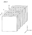
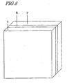
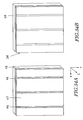
- FIG. 5 is a perspective view illustrating an exemplary process of forming a composite piezoelectric element.
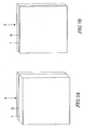
- FIG. 6 is a perspective view illustrating an exemplary process of cutting the composite piezoelectric element.
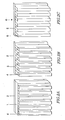
- FIGS. 7A and 7B are perspective views illustrating an exemplary process of reducing a thickness of a plate-like piezoelectric element of the composite plate.
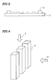
- FIG. 8 is a perspective view illustrating an exemplary process of temporarily fixing the plate-like piezoelectric element.
- FIG. 9 is a perspective view illustrating an exemplary process of working the plate-like piezoelectric element.
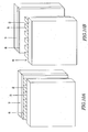
- FIGS. 10A and 10B are perspective views illustrating an exemplary process of transferring the columnar piezoelectric elements onto a resin layer.
- FIG. 11 is a perspective view illustrating an exemplary process of forming a composite piezoelectric element.
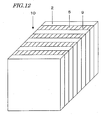
- FIG. 12 is a perspective view illustrating an exemplary process of filling a gap in the composite piezoelectric element with a resin.
- FIG. 13 is a perspective view illustrating an exemplary process of forming a composite piezoelectric element.
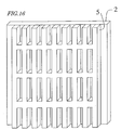
- FIG. 14 is a perspective view showing an exemplary variation of a pattern of columnar piezoelectric elements.
- FIG. 15 is a perspective view showing another exemplary variation of a pattern of columnar piezoelectric elements.
- FIG. 16 is a perspective view showing still another exemplary variation of a pattern of columnar piezoelectric elements.
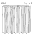
- FIG. 17 is a perspective view showing an exemplary variation of a shape of columnar piezoelectric elements.
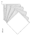
- FIG. 18 is a perspective view showing an exemplary variation of a layered configuration of unit composite sheets.
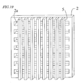
- FIG. 19 is a view showing an exemplary variation of a resin layer constituting a unit composite sheet.
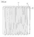
- FIG. 20 is a view showing another exemplary variation of a resin layer constituting a unit composite sheet.
- FIGS. 21A and 21B are perspective views illustrating an exemplary process of preparing a composite plate of the composite piezoelectric element in Embodiment 11 of the present invention.
- FIG. 22 is a perspective view showing a condition in which a resin sheet is stuck on the composite plate of FIGS. 21A and 21B.
- FIG. 23 is a perspective view showing a condition in which a mask pattern is formed on the composite plate of FIG. 22 .
- FIGS. 24A and 24B are perspective views illustrating an exemplary process of working the composite plate of FIG. 23 by using the mask pattern, thereby forming a unit composite sheet.
- FIG. 25 is a sectional view of the unit composite sheet of FIGS. 24A and 24B .
- FIG. 26 is a perspective view showing a working direction for obtaining columnar piezoelectric elements.
- FIG. 27 is a perspective view showing the composite piezoelectric element of Embodiment 11.
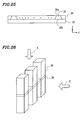
- FIG. 28 is a perspective view illustrating an exemplary process of preparing a composite plate of the composite piezoelectric element in Embodiment 12 of the present invention.
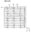
- FIG. 29 is a perspective view showing a condition in which a mask pattern is formed on the composite plate of FIG. 28 .
- FIGS. 30A and 30B are perspective views illustrating an exemplary process of transferring columnar piezoelectric elements and internal conductive elements onto a resin layer.
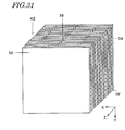
- FIG. 31 is a perspective view showing the composite piezoelectric element of Embodiment 12.
- FIGS. 32A and 32B are perspective views illustrating an exemplary fabrication process of a composite plate of Embodiment 13.
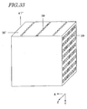
- FIG. 33 is a perspective view showing a composite piezoelectric element of Embodiment 14.
- FIGS. 34A and 34B are perspective views illustrating an exemplary process of preparing a composite plate of the composite piezoelectric element in Embodiment 15 of the present invention.
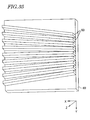
- FIG. 35 is a perspective view showing exemplary shape and arrangement of columnar piezoelectric elements in a unit composite sheet of the composite piezoelectric element in Embodiment 16 of the present invention.
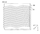
- FIG. 36 is a perspective view showing another example of shape and arrangement of columnar piezoelectric elements in the unit composite sheets of the composite piezoelectric element in Embodiment 16 of the present invention.
- FIG. 37 is a sectional view of an embodiment of an ultrasonic probe according to the present invention.
- FIG. 38A is a graph showing the transmission and receiving waveform characteristic of the ultrasonic probe in the embodiment of the present invention.
- FIG. 38B is a graph showing the frequency band characteristic of the ultrasonic probe in the embodiment of the present invention.
- FIG. 39A is a graph showing the transmission and receiving waveform characteristic of a comparative example of an ultrasonic probe.
- FIG. 39B is a graph showing the frequency band characteristic of the comparative example.
- FIG. 40 is a sectional view of an ultrasonic diagnostic apparatus in an embodiment according to the present invention.
- FIG. 41 is a schematic sectional view showing an ultrasonic probe of the present invention and a driving circuit for the ultrasonic probe.
- FIG. 42 is a schematic diagram showing a configuration of an ultrasonic diagnostic apparatus of the present invention.
- FIGS. 43A to 43F are perspective views illustrating a process of another example in the composite piezoelectric element of Embodiment 15 in the present invention.
- a resin layer 2 is stuck onto one surface of a plate-like piezoelectric element 1, so as to form a composite plate 3.
- a material of the plate-like piezoelectric element 1 lead zirconate titanate-based (PZT) ceramic can be suitably used, for example.
- the plate-like PZT ceramic can be easily and inexpensively prepared by sintering a low-price ceramic green sheet (thickness: about 0.07 mm).
- the ceramic green sheet is a sheet which is not yet sintered and is composed of a ceramic powder and a resin.
- the ceramic green sheet is prepared by a method such as doctor blading, and suitably used for forming a piezoelectric element of a thin-film or layered configuration (such as a laminate substrate).
- the plate-like piezoelectric element 1 can be prepared by cutting a block-like ceramic.
- the method requires high-cost processes such as a cutting and lapping process.
- a method for preparing the plate-like piezoelectric element from the ceramic green sheet does not require the processes of cutting, lapping, and the like, so that the method is advantageous in view of reducing the cost.
- the plate-like piezoelectric element 1 is prepared by sintering the ceramic green sheet, in view of reducing the equipment cost, a number of ceramic green sheets are generally stacked and simultaneously sintered. In this case, so as not to join the stacked upper and lower ceramic green sheets together, the stacking is performed in such a manner that a powder called as a peeling powder such as MgO is sprinkled between respective ceramic green sheets.
- a powder called as a peeling powder such as MgO is sprinkled between respective ceramic green sheets.
- MgO a powder called as a peeling powder such as MgO is sprinkled between respective ceramic green sheets.
- Each of the plate-like piezoelectric element after the sintering is cleaned for removing the peeling powder.
- the size of the plate-like piezoelectric element 1 is about 30 mm square, it is necessary to ensure sufficient strength by setting the thickness to be about 50 ⁇ m or more, so as to facilitate the handling thereof. In the case of a thin plate-like piezoelectric element having
- the resin layer (thickness: 0.025 mm) 2 has the same size in plane as that of the plate-like piezoelectric element 1.
- the resin layer 2 is composed of an epoxy-based tack resin sheet.
- the fabrication of the composite element 3 can be performed as follows. Specifically, an epoxy-based tack resin with a peeling film attached on one face is stacked on the plate-like piezoelectric element 1, and then they are layered 120 times by means of a piston-like jig.
- a pressure is applied to the layered structure of the plate-like piezoelectric element 1 and the resin layer 2, while the layered structure is still in the jig.
- the pressurizing may be performed for 5 minutes while a pressure of about 1 MPa is applied.
- the atmosphere is returned to be atmospheric and the pressure is released. Then, they are held at 150°C for one hour.
- the resin layer 2 is hardened in this way, the layered structure is taken out of the jig. By peeling the peeling film, 120 composite elements 3 can be obtained.
- the plate-like piezoelectric element 1 is preferably formed from a material with high piezoelectric property.
- the material for the plate-like piezoelectric element 1 is not limited to this.
- a ceramic such as lead titanate or barium titanate, or single crystal such as quartz, lithium niobate, or PZT single crystal may be used.
- the method of sticking the epoxy-based tack resin sheet is adopted as the forming method of the resin layer 2 , it is sufficient to adopt a method which can form a resin layer with a uniform thickness on one surface of the plate-like piezoelectric element 1 .
- An arbitrary method for forming the resin layer 2 such as spin coating, screen printing, or the like may be used.
- a working mask 4 is formed on an exposed surface of the plate-like piezoelectric element 1 which constitutes the composite element 3 .
- the working mask 4 used in this embodiment has a stripe pattern.
- the patterning of the stripe pattern is performed so that the interval is also 0.050 mm.
- the width of each stripe portion defines a width of a columnar piezoelectric element to be formed. It is unnecessary that the interval of the stripe portions of the working mask 4 coincides with the width of the stripe portion.
- the working mask 4 is formed by, after a photo-sensitive resin sheet is stuck to the plate-like piezoelectric element 1, exposing and developing the resin sheet by using a photo mask.
- a photo mask In the photo mask, a light blocking pattern for defining the above-mentioned stripe pattern is formed, and the development and exposure can be performed by known photolithographic techniques.
- the pattern of the photo mask By changing the pattern of the photo mask, the shape and the size of the pattern of the working mask 4 can be arbitrarily set.
- the sand blasting is a working process in which fine particles (particles of alumina or diamond) are injected together with compressed air, so that an object to be worked is broken by means of impact.
- a soft material such as a resin is not broken, but a hard material such as ceramic can be selectively broken by brittle fracture. Accordingly, by performing the sand blasting with the working mask 4 of resin, only a region of the surface of the plate-like piezoelectric element 1 which is not covered with the stripe portion of the working mask 4 can be selectively chipped, so as to form a cutting groove in the region. As the sand blasting progresses, the cutting groove formed in the exposed surface of the plate-like piezoelectric element 1 becomes deeper. Eventually, the cutting groove reaches the resin layer 2 disposed on the back side of the plate-like piezoelectric element 1 .
- the resin layer 2 is not broken by the sand blasting similarly to the working mask 4 , so that when the cutting groove formed in the plate-like piezoelectric element 1 reaches the resin layer 2, the resin layer 2 is hardly worked.
- a plurality of columnar piezoelectric elements 5 can be formed from the plate-like piezoelectric element 1.
- FIG. 2B for simplicity, only six columnar piezoelectric elements 5 are shown. Actually, 300 columnar piezoelectric elements 5 are simultaneously formed.
- a wide face of the plate-like piezoelectric element 1 can be collectively processed at high speed with high precision.
- the sand blasting is not suitable in the case where a ratio of a depth to a width of an opening portion of the working mask 4 (aspect ratio) is high.
- a depth direction of the cutting groove formed by the sand blasting is not parallel to but perpendicular to a longitudinal direction of the columnar piezoelectric element 5 to be formed. Accordingly, when a depth of the cutting groove formed by the working is D, and a width of the cutting groove is W, the ratio D/W in this embodiment is about 1.
- the ratio D/W defines the aspect ratio of the cutting groove.
- the ratio D/W is set in the range of about 1 to 2. In addition, when fine working is especially required, the ratio D/W is desired to be 1 or less.
- the working mask 4 is peeled. In this way, a unit composite sheet 6 having a configuration in which a number of columnar piezoelectric elements 5 are held by the resin layer 2 can be fabricated.
- Each of the columnar piezoelectric elements 5 has the sizes of 30 mm in Y direction, about 40 to 50 ⁇ m in X direction, and 50 ⁇ m in Z direction.
- a section perpendicular to the longitudinal direction of the columnar piezoelectric element 5 is shown in FIG. 3 .
- the section of the columnar piezoelectric element obtained in this embodiment is substantially a trapezoid.
- a width in the upper face of the columnar piezoelectric element 5 is about 40 to 45 ⁇ m and a width in the lower face thereof is about 55 to 60 ⁇ m. The reason why a taper is formed in the side face is that a side edge is generated by the sand blasting.
- the upper face of the columnar piezoelectric element 5 is covered with the working mask 4 , the upper face is not subjected to the sand blasting. Since the plate-like piezoelectric element 1 in this embodiment is fabricated by sintering, the surface there of is a unprocessed surface. The upper face and the lower face of the columnar piezoelectric element 5 which are not subjected to the sand blasting are also the unprocessed surfaces after the working. The side face of the columnar piezoelectric element 5 is worked, so that the side face is not the unprocessed surface.
- the piezoelectric element 5 is formed by working the piezoelectric element in a direction indicated by an arrow A , it is extremely difficult to form a columnar piezoelectric element having an aspect ratio of 5 or more.
- the piezoelectric element is worked in a direction indicated by an arrow B in FIG. 4 , the working depth is shallow, and full advantages of the sand blasting such as the high-speed property and the collective workability can be taken.
- the cutting method can work the plate-like piezoelectric element 1 into columnar shape, the method is not limited to the sand blasting. Other cutting methods such as dicing, ultrasonic machining, laser processing, or etching may be arbitrarily employed.
- 120 unit composite sheets each of which is prepared by the above-described method are prepared, and a process of lamination and integration is performed.
- a large area of the composite sheets can be simultaneously processed by the sand blasting, so that a time required for cutting the 120 sheets of the composite plates 3 having the above-mentioned sizes is 2 hours or less which is very short. Therefore, it is possible to shorten the production time of the unit composite sheets and to reduce the cost.
- the unit composite sheets 6 are layered with another resin layer 2' which is different from the resin layer 2 constituting the unit composite sheet interposed therebetween.
- the unit composite sheets 6 are layered.
- the unit composite sheets 6 are disposed in such a manner that the columnar piezoelectric elements 5 in each layer are substantially parallel to each other.
- two epoxy-based tack resin sheets each having sizes of 30 mm in X direction, 30 mm in Y direction, and 0.025 mm in Z direction are disposed.
- positions of the columnar piezoelectric elements 5 disposed in each of adjacent two unit composite sheets are mutually matched and aligned. However, in actuality, the positions of the columnar piezoelectric elements 5 may be shifted for every unit composite sheet.
- the thus-layered structure is left for 10 minutes while applying a pressure of about 0.1 MPa at 120°C and 0.1 Torr or less. Thereafter, the pressure is returned to be atmospheric, and the layered structure is heated for 1 hour at 180°C without applying a pressure.
- the resin layers 2 and 2' are hardened, and the layered structure is integrated, thereby obtaining a composite piezoelectric element 10 as the composite sheet layered structure.
- the composite piezoelectric element 10 is cut along a plane perpendicular to the longitudinal direction (Y direction) of the columnar piezoelectric elements 5 (a plane parallel to the X-Z plane) and separated into a plurality of composite piezoelectric elements 10' .
- the cutting pitch is 0.3 mm
- the cutting margin is 0.1 mm
- 100 composite piezoelectric elements 10' having the sizes of 30 mm in X direction, 0.20 mm in Y direction, and 12 mm in Z direction can be obtained from one composite piezoelectric element 10 .
- the size in Z direction of the composite piezoelectric element 10' after the cutting can be adjusted by changing the cutting pitch.
- the size in Z direction of the composite piezoelectric element 10' after the cutting be set in the range of 0.2 to 2 mm.
- a polarization process is performed at 180°C and 400 V, so as to obtain a composite piezoelectric element exhibiting piezoelectric characteristics.
- direct handling is not performed with respect to the respective columnar piezoelectric elements 5 , and it is unnecessary to arrange a number of columnar piezoelectric elements 5 on a substrate one by one.
- the fabrication method it is possible to inexpensively fabricate a composite piezoelectric element in a short time with good yield without using expensive equipment as compared with the prior-art fabrication method.
- Both of the upper and lower faces of the thus-fabricated composite piezoelectric element are unprocessed surfaces, as described above, because a piezoelectric ceramic prepared by sintering a thin green sheet is used.
- part of the unprocessed surface is covered with a resin, and is not subjected to the working, so that the part of the unprocessed surface exists in the final composite piezoelectric element.
- the unprocessed surface of the piezoelectric element is dense as compared with the worked surface, and the property resistant to environments of the unprocessed surface is high. Thus, as compared with the case where the whole of the circumference is subjected to the sand blasting, preferred characteristics can be exhibited.
- the composite piezoelectric element of this embodiment has a multi-layer configuration arranged along a thickness direction (Z direction) of the unit composite sheets. In other words, among a plurality of columnar piezoelectric elements arranged in two-dimension along X-Z plane, respective columns arranged in X direction are mutually separated by the resin layer. Since the composite piezoelectric element of this embodiment has such a layered configuration, an effect that the interference in lateral direction can be reduced is attained.
- the composite piezoelectric element according to this embodiment is a composite piezoelectric element suitable for a high-frequency ultrasonic piezoelectric transducer.
- the second embodiment is different from the first embodiment in that a process of making the plate-like piezoelectric element 1 of the composite plate 3 thinner is additionally performed.
- the other production processes are the same as those in the first embodiment.
- a composite plate 3 shown in FIG. 7A is prepared by the above-mentioned method.
- a process for reducing a thickness (a size in Z direction) of a plate-like piezoelectric element 1 of the composite plate 3 is performed, so as to form a thin composite plate 3 shown in FIG. 7B.
- Mask materials and exposing devices are improved, so that a working mask having a fine pattern of about 0.020 mm can be formed with high accuracy at the present time.
- the width of the stripe portion of the mask defines the width of the columnar piezoelectric element, so that a section of the columnar piezoelectric element is smaller as compared with the composite piezoelectric element in the first embodiment.
- the plate-like piezoelectric element 1 which is to be subjected to sand blasting is made thin, it is possible to form a columnar piezoelectric element having a reduced width with high accuracy while the aspect ratio of the cutting groove is maintained to be small. Processes after the process of forming the working mask are the same as those in the first embodiment.
- the thus-prepared unit composite sheets are layered and integrated by the above-described method, and then cutting, electrode formation, and polarization processes are performed, thereby obtaining 150 composite piezoelectric elements each having sizes of 30 mm in X direction, 30 mm in Y direction, and 0.100 mm in Z direction.
- a low-price PZT ceramic is used as the plate-like piezoelectric element 1, and a composite piezoelectric element in which a number of columnar piezoelectric elements each having a section size S of about 0.020 mm are arranged is produced.
- a length (a size in Y direction) of the columnar piezoelectric element in the final composite piezoelectric element is " L"
- an aspect ratio US of the columnar piezoelectric element is 5 or more, so that a configuration suitable for transmitting and receiving high-frequency ultrasonic waves.
- a process of temporarily fixing a plate-like piezoelectric element 1 to a glass substrate 7 by means of an adhesive sheet 8 is performed.
- the plate-like piezoelectric element 1 a piezoelectric ceramic having sizes of 30 mm in X direction, 30 mm in Y direction, and 0.050 mm in Z direction is used as in the first embodiment.
- the adhesive sheet 8 a thermally peeling sheet is used as the adhesive sheet 8 .
- the adhesive sheet 8 is not limited to the thermally peeling sheet, but may be a sheet which satisfies the following conditions.
- the sheet can hold the plate-like piezoelectric element 1, the plate-like piezoelectric element 1 is not peeled off from the peeling sheet in the cutting process, and the sheet can be peeled off by any action after the working.
- a peeling sheet by UV light irradiation can be used as the adhesive sheet 8 .
- a plurality of cutting grooves parallel to the plate-like piezoelectric element 1 are formed, so as to cut the plate-like piezoelectric element 1, thereby forming a plurality of columnar piezoelectric elements 5 .
- a working mask 4 is formed, and then sand blasting is performed.
- a configuration in which columnar piezoelectric elements 5 are temporarily fixed on the substrate 7 by means of the adhesive sheet 8 can be obtained.
- a width and an interval of the stripe portion of the working mask are set to be 0.050 mm.
- the plurality of columnar piezoelectric elements 5 temporarily fixed on the substrate 7 are disposed so as to face a sheet-like resin layer 2 .
- the resin layer 2 an epoxy-based tack resin sheet having a thickness of about 0.050 mm can be suitably used.
- a pressure of about 0.1 MPa is applied, for example, and heating is performed for 10 minutes at 120°C.
- the pressurizing and heating process causes the resin layer 2 and the columnar piezoelectric elements 5 to adhere, and a thermally peeling effect of the adhesive sheet 8 is exhibited. Accordingly, as shown in FIG. 10B, the columnar piezoelectric elements 5 are peeled off from the adhesive sheet 8 , and transferred to the resin layer 2 .
- epoxy-based tack resin sheet is used as the resin layer 2 , but the resin layer 2 may be another type of adhesive sheet if the same effects can be attained.
- a liquid resin or the like may be applied onto the columnar piezoelectric elements 5 by printing or other methods, so as to form a layer of resin, and then the resin layer may be hardened and peeled off.
- the 300 columnar piezoelectric elements 5 are moved onto the resin layer 2 while maintaining the arrangement on the substrate 7 with high accuracy by the above-mentioned transferring process. In this way, a unit composite sheet is prepared.
- a resin layer having sizes of 30 mm in X direction, 30 mm in Y direction, and 0.050 mm in Z direction is disposed on the uppermost portion.
- a pressure of about 0.1 MPa is applied, and the layered structure is held for 10 minutes.
- the atmosphere is recovered to be atmospheric, and the pressure is released, and then the layered structure is held at 180°C for 1 hour.
- the resin layer 2 is hardened, and the layered structure is integrated, so as to form a composite piezoelectric element 10 .
- the resin layer 2 used for the transferring is only subjected to the heat history of 120°C or less in the transferring from the thermally peeling sheet, so that the adhesive force is kept after the transferring.
- it is unnecessary to interpose an additional adhesive sheet for integrating the layered structure. Accordingly, the time required for a process of integrating the layered structure can be shortened as compared with the case of Embodiment 1, and the lower cost can be realized.
- the integrated composite piezoelectric element 10 has a rectangular parallelepiped shape having sizes of 30 mm in X direction, 30 mm in Y direction, and 12 mm in Z direction. In this composite piezoelectric element, 36,000 columnar piezoelectric elements are held in parallel by means of the resin layer.
- the composite piezoelectric element of this embodiment is a composite piezoelectric element suitable for a high-frequency ultrasonic piezoelectric transducer.
- This embodiment is different from the third embodiment only in that a process of making the plate-like piezoelectric element 1 of the composite plate 3 thin is additionally performed, and the width of the stripe portion of the working mask is narrow so as to be about 0.02 mm in fabrication.
- the process of making the plate-like piezoelectric element 1 thin, and the process of forming the working mask are the same as those described in the second embodiment.
- a gap portion of the composite piezoelectric element is impregnated with a filling resin 9 , and then the resin is hardened. Thereafter, similarly to the above-described respective embodiments, the cutting process, the electrode forming process, and the polarization process for the composite piezoelectric element 10 are performed.
- a gap portion exists between the columnar piezoelectric elements 5 arranged on each unit composite sheet, and the gap portion is filled with air. Since the air is also dielectric, it is unnecessary to fill the gap portion with another dielectric material so as to function as a composite piezoelectric element. However, if the gap portion is embedded with a dielectric material which can be hardened, and then the material is hardened, the mechanical strength of the composite piezoelectric element can be improved, and preferably the oscillation mode of the composite piezoelectric element 10 can be appropriately adjusted.
- the gap portion formed between the columnar piezoelectric elements 2 is filled with a resin 9 as a dielectric element, so as to improve the mechanical strength of the composite piezoelectric element 10.
- a breakage hardly occurs in process steps such as the cutting steps.
- the production yield is increased, and the production cost can be further reduced.
- the gap portion is embedded by the resin 9 , two faces on which the electrodes are formed are not conducted via the gap portion. For this reason, if the electrodes are formed by using electroless plating, it is possible to easily prevent the two electrodes from being short-circuited. Accordingly, electrodes can be collectively formed for a number of composite piezoelectric elements, and the cost can be further reduced.
- respective columnar piezoelectric elements 5 are surrounded by a resin.
- a plurality of composite sheets are layered in such a manner that respective columnar piezoelectric elements 5 are disposed between resin layers 2 .
- a pressure to be applied to the layered structure is increased. Specifically, in an atmosphere of 120°C and 0.1 Torr or less, a pressure of 1 MPa is applied to the layered structure, and the layered structure is left for 10 minutes. Thereafter, the pressure is returned to be the atmospheric pressure, and the layered structure is heated at 180°C for one hour while the atmospheric pressure is applied to the layered structure.
- the gap portions are filled with the resin by the above-mentioned method, so as to improve the mechanical strength as a composite piezoelectric element.
- a breakage hardly occurs in process steps s such as the cutting steps, and the production yield is increased.
- the production cost can be reduced.
- electroless plating can be used for the electrode formation, so that electrodes can be collectively formed for a large number of composite piezoelectric elements.
- the low cost can be realized.
- this embodiment can omit the resin filling process after the layering, so that the production time can be shortened, and the production cost can be further reduced.
- the shapes of all columnar piezoelectric elements in a unit composite sheet are linear, and the columnar piezoelectric elements are arranged in parallel.
- the shape of a piezoelectric element in a unit composite sheet is not limited to be linear.
- the arrangement is not limited to the parallel arrangement.
- various shapes of columnar piezoelectric elements may be formed.
- FIG. 14 shows an example in which the columnar piezoelectric elements are not arranged in parallel.
- FIG. 15 shows an example in which the columnar piezoelectric element does not extend linearly, but bends.
- FIG. 16 shows an example in which the columnar piezoelectric elements are coupled to each other, so as to form a lattice pattern.
- FIG. 17 shows an example in which a section of the columnar piezoelectric element is not square, but polygonal. In order to form columnar piezoelectric elements having such a shape in section by sand blasting, it is sufficient to regulate an injection time of particles in the sand blasting.
- the section of the columnar piezoelectric element perpendicular to the longitudinal direction thereof is not necessarily a polygon constituted by linear sides. Alternatively, the section has a shape in which part of the section may include a curve.
- a working mask After a working mask is removed, for example, it is possible to change an exposed surface of a columnar piezoelectric element to a gently curved face by additionally performing the sand blasting or other workings in a short time. It is preferred that the side face of the columnar piezoelectric element be a curved face, because interference of oscillation mode hardly occurs between adjacent piezoelectric elements.
- unit composite sheets when unit composite sheets are to be layered, unit composite sheets having the same shape are used, and the unit composite sheets are disposed in such a manner that columnar piezoelectric elements are arranged in the same direction.
- the present invention is not limited to the arrangement. For example, as shown in FIG. 18 , directions of the respective unit composite sheets may be shifted, and the longitudinal direction of the columnar piezoelectric elements may be rotated for every unit composite sheet.
- the unit composite sheets shown in FIG. 14 to FIG. 17 may be layered and integrated in arbitrary combinations.
- the cut face is not necessarily a plane, but a curved face.
- a resin layer of the unit composite sheet is not necessarily flat, but bent.
- a resin layer for holding a piezoelectric element a continuous sheet without any openings is used.
- the resin layer is not limited to such a type of sheet.
- a resin layer 2 in which an opening portion 2a is formed in part may be used.
- a resin layer in which a thickness of one part is different from a thickness of the other part may be used.
- the dispositional relationship of columnar piezoelectric elements on respective unit composite sheets is fixed.
- a relative dispositional relationship between columnar piezoelectric elements on one unit composite sheet and columnar piezoelectric elements on another unit composite sheet may change.
- the alignment for the columnar piezoelectric elements is not particularly required.
- the relative dispositional relationship of the columnar piezoelectric elements is defined with high accuracy for some reasons, it is preferred that the alignment by image recognition be performed in the layering process.
- a plurality of projections 11 may be periodically arranged in a resin layer of the unit composite sheet (a face which is not in contact with columnar piezoelectric elements).
- the arranged pitch of the projections 11 is set so as to be equal to the pitch of columnar piezoelectric elements 5 on another unit composite sheet disposed oppositely to the resin layer 2 .
- the size and shape of each projection 11 is designed so that, when the unit composite sheets are layered, a columnar piezoelectric element is fitted in a recess portion formed between adjacent two projections 11 .
- Such projections 11 can exhibit a function of reducing a gap between adjacent columnar piezoelectric elements, and thus improving the strength of the composite piezoelectric element.
- a gap portion is filled with a resin as in the fifth embodiment, all gaps can be filled with a reduced amount of resin.
- the layering and integration process can be performed at a lower pressure.
- a fabrication method of this embodiment will be described with reference to FIG. 21 to FIG. 27 .
- a layered structure 33 in which a piezoelectric element 31 and a conductive element 32 are alternately layered is formed.
- the sizes of each piezoelectric element 31 are, for example, 0.5 mm (500 ⁇ m) in X direction, 20 mm in Y direction, and 20 mm in Z direction.
- the sizes of each conductive element 32 are 0.01 mm (10 ⁇ m) or less in X direction, 20 mm in Y direction, and 20 mm in Z direction.
- a layered structure 33 having sizes of 20 mm in X direction, 20 mm in Y direction, and 20 mm in Z direction is formed.
- the sizes of the piezoelectric element 31 and the conductive element 32 and the sizes of the layered structure 33 are not limited to these values, but can be appropriately selected to be preferable sizes in accordance with the intended use.
- a material which constitutes the piezoelectric element 31 a material with high piezoelectric properties is preferable.
- a ceramic such as lead zirconate titanate, lead titanate, barium titanate, or the like, or a single crystal constituted by quartz, lithium niobate, lead zirconate titanate can be used.
- the conductive element 32 a material with high conductivity is sufficient, and the material is selected from metals such as gold, silver, platinum, and nickel, or carbon, depending on the cost and the conductivity required for the intended use.
- the piezoelectric element 31 and the conductive element 32 having the above-mentioned sizes may be joined with an appropriate adhesive, so as to form a layered structure.
- a ceramic green sheet made of the above-mentioned material and a conductive paste may be layered and sintered, so as to form a layered structure 33 .
- the layered structure 33 is cut along a plane (X-Y plane) parallel to the layering direction (X direction), thereby obtaining a plurality of composite plates 34 .
- the layered structure was cut at pitches of 0.1 mm, and then the composite plate 34 was lapped so as to have a thickness of 0.05 (50 ⁇ m). In this way, 200 composite plates 34 can be obtained from the layered structure 33 .
- various work machine using a wire saw, laser, ultrasonic, or the like can be used, instead of the dicing machine.
- the pitches of cutting and the thickness of each composite plate 34 other values can be selected in accordance with the intended use.
- a resin adhesive sheet 20 including a resin layer 35 and a peeling film 36 is prepared, and the resin layer 35 is stuck to one face of the composite plate 34 .
- the sizes of the resin layer 35 are, for example, 20 mm in X direction, 20 mm in Y direction, and 0.025 mm (25 ⁇ m) in Z direction.
- the sticking of the resin adhesive sheet 20 is performed as follows, for example. First, an epoxy-based tack resin 35 with a peeling film 36 attached on one surface thereof is layered on a composite plate 34. The layering is performed 200 times by piston-like jig.
- a pressure of about 1 MPa is applied to the jig, and the layered structure held by the jig is heated at 120°C for 5 minutes under a reduced pressure condition of 0.1 Torr or less. Thereafter, the pressure is returned to the atmospheric pressure, and the layered structure is heated at 180°C after releasing the pressurization by the jig. Thus, the epoxy-based tack resin is hardened. Thereafter, the layered structure is cooled to a room temperature, and the peeling film 36 is removed.
- the resin layer 35 is formed on the composite plate 34 by using the resin adhesive sheet 20 .
- a resin layer having a uniform thickness may be formed on one surface of the composite plate 34 by spin coating, screen printing, or other methods.
- a working mask 37 is formed on a surface of the composite plate 34 on which the resin layer 35 is not formed.
- the working mask 37 includes a pattern 37a completely covering an upper portion of the conductive element 32 of the composite plate 34 and a pattern 37b for forming a plurality of columnar piezoelectric elements from the composite plate 34 .
- Widths of the pattern 37b are 0.05 mm (50 ⁇ m), respectively, and intervals of the pattern 37b are also 0.05 mm.
- the widths of the pattern 37b are not necessarily equal to the intervals thereof.
- the working mask 37 is formed in such a manner that, after a photo-sensitive resin sheet is stuck to the composite plate 34 , the resin sheet is exposed and developed by using a photo mask.
- a photo mask In the photo mask, a light blocking pattern for defining the patterns 37a and 37b is formed.
- the development and exposure can be performed by known photolithographic techniques. By changing the pattern of the photo mask, shapes and sizes of patterns of the working mask 37 can be arbitrarily set.
- the sand blasting is the working process by injecting fine particles (particles such as alumina, diamond, or the like) together with compressed air (or fluid such as water), so as to break the object to be worked by means of impact.
- a soft material such as a resin is not broken, but a hard material such as a ceramic can be selectively broken by brittle fracture. Accordingly, by performing the sand blasting by using the resin working mask 37 , a region of the surface of the composite plate 34 which is not covered with the pattern 37b can be selectively cut away, and a cutting groove can be formed in the portion. As the sand blasting progresses, the cutting groove formed in the exposed surface of the composite plate 34 becomes deeper, and eventually the cutting groove reaches the resin layer 35 disposed on the back face side of the composite plate 34 .
- the resin layer 35 is not broken by the sand blasting, so that the resin layer 35 is hardly worked even if the cutting groove formed in the composite plate 34 reaches the resin layer 35 .
- a portion in which the conductive elements 32 are formed is covered with the pattern 37a , so that the conductive elements 32 are not cut away at all.
- FIG. 24A a composite plate 34 in which portions covered with the working mask 37 including the patterns 37a and 37b are left can be obtained.
- the cutting groove is formed between the patterns 37b , but separated by the pattern 37a .
- the working mask 37 is peeled off, thereby obtaining a unit composite sheet 40 in which a plurality of columnar piezoelectric elements 39 , and a plurality of internal conductive elements 38 extending across the respective columnar piezoelectric elements 39 in a direction intersecting the longitudinal direction of the columnar piezoelectric elements 39 , for coupling adjacent columnar piezoelectric elements 39 are formed on the resin layer 35 .
- FIG. 24B a composite sheet 40 in which a plurality of columnar piezoelectric elements 39 , and a plurality of internal conductive elements 38 extending across the respective columnar piezoelectric elements 39 in a direction intersecting the longitudinal direction of the columnar piezoelectric elements 39 , for coupling adjacent columnar piezoelectric elements 39 are formed on the resin layer 35 .
- the word “cross” includes not only the case where the internal conductive elements 38 cross the columnar piezoelectric elements 38 so as to completely divide them, but also the case where the internal conductive elements 38 cross the columnar piezoelectric elements 39 so as to be in contact with part of the columnar piezoelectric elements 39 .
- a wide surface of the composite plate 34 can be collectively worked at high speed with high precision.
- the sand blasting is an inappropriate cutting method in the case where a ratio (aspect ratio) of a depth to a width of an opening portion of the working mask 37 is large.
- a depth direction of the cutting groove formed by the sand blasting is not in parallel to, but perpendicular to the longitudinal direction of the columnar piezoelectric elements 39 to be formed.
- a ratio D/W in this embodiment is about 1.
- the ratio D/W defines the aspect ratio of the cutting groove.
- the ratio D/W be set in the range of about 1 to 2. In the case where minute working is particularly required, it is desired that the ratio D/W be set to be 1 or less.
- the working of the piezoelectric element is performed in the direction perpendicular to the longitudinal direction (Y direction) of the columnar piezoelectric elements 39 . Therefore, even if the " aspect ratio of the columnar piezoelectric element " has a value exceeding 5, the aspect ratio of the cutting groove can be reduced. For this reason, a columnar piezoelectric element having an aspect ratio which is impossible by the prior art can be easily formed.
- FIG. 25 shows a section perpendicular to the longitudinal direction of the columnar piezoelectric element 39 .
- the section of the columnar piezoelectric element 39 obtained in this embodiment is asymmetric for the rotation of 180 degrees with respect to a center axis of the columnar piezoelectric element 39 .
- the section of the columnar piezoelectric element 39 is substantially a trapezoid.
- a width in an upper face 39a of the columnar piezoelectric element 39 is about 40 to 45 ⁇ m, and a width of a lower face 39b is about 55 to 60 ⁇ m.
- tapers are formed on side faces is that side etching occurs by the sand blasting.
- the piezoelectric element is worked in a direction indicated by arrow B, so that the working depth is shallow.
- the high-speed property and collective working possibility of the sand blasting can be taken advantage of.
- the columnar piezoelectric elements 39 can be formed from the piezoelectric element while the internal conductive elements 38 disposed for coupling the adjacent piezoelectric elements 39 are left.
- the cutting method is not limited to the sand blasting. If the method can work a composite plate 34 into columnar piezoelectric elements, any cutting method such as dicing, ultrasonic working, or laser working may arbitrarily be employed.
- 200 unit composite sheets 40 are prepared.
- the time required for working the 200 composite sheets having the above-mentioned sizes is about 2 hours or less which is very short. Accordingly, the production time for the unit composite sheets can be shortened, and the cost can be reduced.
- a plurality of unit composite sheets 40 are layered and integrated. As shown in FIG. 27 , the unit composite sheets 40 are layered with a resin layer 35' which is different from the resin layer 35 constituting the unit composite sheet 40 interposed therebetween. In FIG. 27 , for simplicity, only six unit composite sheets 40 are shown. In actuality, 200 unit composite sheets 40 are layered. In the uppermost portion, one epoxy-based tack resin sheet having sizes of 20 mm in X direction, 20 mm in Y direction, and 0.05 mm in Z direction is disposed.
- the alignment may be performed in such a manner that the positions of the internal conductive elements 38 align in the X direction. That is, if there is no displacement in the X direction, some displacement in the Y direction does not cause a serious problem. Accordingly, expensive equipment for alignment is not required, and the time required for alignment is short. Thus, the cost can be reduced.
- the layered structure is left for 10 minutes at 120 °C and 0.1 Torr or less while applying a pressure of 0.1 MPa. Thereafter, the pressure is returned to the atmospheric pressure, and the layered structure is heated at 180°C for 1 hour without applying any pressure.
- the resin layers 35 and 35' are hardened, so that the layered structure is integrated.
- a composite piezoelectric element 41 as the layered structure of composite sheets can be obtained.
- the obtained composite piezoelectric element 41 has a cubic shape having sizes of 20 mm in X direction, 20 mm in Y direction, and 20 mm in Z direction.
- 40,000 columnar piezoelectric elements 39 extending in the X direction in the figure, and 8,000 internal conductive elements 38 extending in the Y direction are formed.
- the columnar piezoelectric elements 39 are arranged in matrix constituting rows (Y direction) and columns (Z direction) in a plane (Y-Z plane) perpendicular to the longitudinal direction (X direction) thereof.
- the respective columns of the columnar piezoelectric elements 39 are isolated by the resin layers 35 and 35' .
- the section (Y-Z plane) perpendicular to the longitudinal direction (X direction) of each columnar piezoelectric element 39 is a trapezoid.
- the internal conductive elements 38 extend across the respective columnar piezoelectric elements 39 in the row direction of the columnar piezoelectric elements 39 so as to couple the columnar piezoelectric elements 39 arranged in the row direction.
- the columnar piezoelectric elements 39 separated by crossing the internal conductive elements 38 are in contact with the internal conductive elements 38 and electrically connected thereto. Accordingly, the internal conductive elements 38 electrically connects the plurality of columnar piezoelectric elements 39 in each column.
- end portions of each internal conductive element 38 are exposed. Accordingly, the respective columnar piezoelectric elements 39 can be completely and easily connected to an external circuit via the internal conductive elements 38 .
- the unit composite sheets 40 are layered in the thickness direction (Z direction).
- the respective columns arranged in the Y direction are mutually isolated by the resin layer. With such a layered configuration, interference hardly occurs between the columnar piezoelectric elements isolated by the resin layer.
- each unit composite sheet 40 of this embodiment a gap between the columnar piezoelectric elements 39 is not filled with a resin, but a space is formed.
- a resin may be poured into the space, or the space may be left so that the space between the columnar piezoelectric elements 39 is filled with the air.
- the direct handling or arrangement of the columnar piezoelectric elements or internal conductive elements are not required.
- the precise alignment for arranging the columnar piezoelectric elements in matrix is not required. Accordingly as compared with the prior-art fabrication method, the production yield is good in a short time, and the fabrication can be performed by using inexpensive fabrication equipment.
- the composite plate 34 is temporarily fixed onto a substrate 43 such as a glass substrate by means of an adhesive sheet 44 .
- an adhesive sheet 44 a thermally peeling sheet is employed in this embodiment.
- the adhesive sheet 44 is not limited to the thermally peeling sheet, but may be an adhesive sheet which can hold the composite plate 34 and from which the composite plate 34 is not peeled during the cutting process, but is peeled by means of any action after the process.
- a peeling sheet by UV light irradiation can be used as the adhesive sheet 44 .
- the composite plate 34 is worked, so as to form a glass substrate 43 in which a plurality of columnar piezoelectric elements 39 and a plurality of internal conductive elements 38 extending across the plurality of columnar piezoelectric elements 39 in a substantially perpendicular manner, and coupling the columnar piezoelectric elements 39 are held by the adhesive sheet 44 , as shown in FIG. 29 .
- a working mask is formed, and then sand blasting is performed.
- the columnar piezoelectric elements 39 and the internal conductive elements 38 for coupling them which are temporarily fixed to the substrate 43 are disposed so as to face a sheet-like resin layer 35 .
- the resin layer 35 an epoxy-based tack resin sheet having a thickness of about 0.050 mm can be suitably used.
- the resin layer 35 , and the columnar piezoelectric elements 39 and the internal conductive elements 38 are caused to adhere, and the thermally peeling effect of the adhesive sheet 44 is exhibited. Accordingly, as shown in FIG. 30B , the columnar piezoelectric elements 39 and the internal conductive elements 38 are peeled from the adhesive sheet 44 , and transferred onto the resin layer 35 .
- the epoxy-based tack resin sheet is used as the resin layer 35 .
- the resin layer 35 may be another type of adhesive sheet, if the same effects can be attained.
- a liquid resin or the like is applied to the columnar piezoelectric elements 39 and the internal conductive elements 38 by printing or other methods, and a resin layer is formed. Thereafter, the resin is hardened, and then peeled off.
- a resin layer 35' having sizes of 20 mm in X direction, 20 mm in Y direction, and 0.050 mm in Z direction is disposed on the uppermost portion.
- the layered structure is held for 10 minutes while a pressure of 0.1 MPa is applied.
- the atmosphere is returned to the atmospheric condition, and the pressure is released, the layered structure is held at 180°C for 1 hour. In this way, the resin layer 35' is hardened, and the layered structure is integrated, thereby forming a composite piezoelectric element 42 .
- the resin layer 35 used for the transferring in this embodiment is only subjected to the heat history of 120°C or less during the transferring from the thermally peeling sheet, so that the adhesive strength thereof is maintained after the transferring. Therefore, when the layered structure is to be integrated, it is unnecessary to interpose an additional adhesive sheet. Accordingly, the time required for integrating the layered structure is shortened as compared with the case of Embodiment 11, and the cost can be further reduced.
- the integrated composite piezoelectric element 42 has a cubic shape having sizes of 20 mm in X direction, 20 mm in Y direction, and 20 mm in Z direction.
- 8,000 internal conductive elements 38 and 40,000 columnar piezoelectric elements 39 are held in parallel by the resin layer 35 .
- This embodiment describes a method of fabricating a composite piezoelectric element 41' including a layer of internal conductive elements 38 arranged in column direction of the columnar piezoelectric elements 39 obtained by cutting the composite piezoelectric elements 41 and 42 obtained in Embodiments 11 and 12 in parallel to the internal conductive elements 38 by a dicing machine, as shown in FIG. 32 .
- cutting is performed between columns of internal conductive elements 38 arranged in the X direction at pitches of 0.5 mm with a cutting margin of 0.1 mm, so as to obtain a composite piezoelectric element 41' having sizes of 20 mm in X direction, 20 mm in Y direction and 0.4 mm in Z direction and including a layer of internal conductive elements 38 .
- Electrodes are formed on both cut faces, and polarization process is performed by applying a voltage across the internal conductive element 38 and the electrodes on both cut faces, thereby exhibiting piezoelectric characteristics in the columnar piezoelectric elements 39 .
- the ratio (aspect ratio) of a length L in a longitudinal direction of each columnar piezoelectric element to a size S of a section perpendicular to the longitudinal direction is 8 (0.4 mm / 0.05 mm).
- the composite piezoelectric element 41' of this embodiment satisfies the condition of the aspect ratio of 5 or more with which the performances are the best in the 1-3 type composite piezoelectric element.
- the internal conductive element 38 is disposed in a substantially middle position in the longitudinal direction. This configuration is equivalent to a condition where two composite piezoelectric elements having a half of the thickness are connected in parallel.
- a driving signal is applied to the internal conductive element 38 , the capacity of the composite piezoelectric element is increased by four times as compared with the initial composite piezoelectric element.
- an electric impedance is about 1/4, so that a composite piezoelectric element with a larger aspect ratio and reduced electric impedance can be realized.
- a composite piezoelectric element having a layer of internal conductive elements is fabricated.
- the cutting position it is possible to form a composite piezoelectric element having the arbitrary number of internal electrodes.
- another working machine such as a wire saw, a laser, or the like may be used, instead of the dicing.
- a gap portion exists between the columnar piezoelectric elements 39 arranged on each unit composite sheet, and the gap portion is filled with air. Since the air is dielectric, it is unnecessary to fill the gap portion with another dielectric material, in order to function as a composite piezoelectric element. However, if the gap portion is embedded with a dielectric material which can be hardened, and the material is hardened, the mechanical strength of the composite piezoelectric element can be increased. In addition, it is preferred that the oscillation mode of the composite piezoelectric elements 41 and 42 be appropriately adjusted.
- the pressure to be applied to the lamination is increased. Specifically, in an atmosphere of 120°C and 0.1 Torr or less, a pressure of about 1 MPa is applied to the layered structure, and then the layered structure is left for 10 minutes. Thereafter, the pressure is returned to be atmospheric, and the layered structure is heated at 180°C for 1 hour while applying the pressure.
- the gap portions are filled with the resin as described above, so that the mechanical strength as the composite piezoelectric element can be increased.
- breakage in the processes such as cutting hardly occurs, and the production yield is increased.
- the production cost can be reduced.
- electroless plating can used for forming electrodes, so that the electrodes can be collectively formed for a large number of composite piezoelectric elements. Thus, the lower cost can be realized.
- a composite plate used for a unit composite sheet is produced in such a manner that a groove is formed in a plate-like piezoelectric element and the groove is filled with a conductive element.
- a plate-like piezoelectric element 47 having sizes of 20 mm in X direction, 20 mm in Y direction, and 0.05 mm in Z direction is fixed on a substrate 43 such as a glass substrate via a thermally peeling sheet 46 stuck onto the substrate 43 .
- a substrate 43 such as a glass substrate
- a thermally peeling sheet 46 stuck onto the substrate 43 .
- grooves 45 extending in the Y direction at pitches of 0.5 mm (width: about 0.03 mm) are formed.
- the thus-formed grooves 45 are filled with a conductive element 32 .
- the plate-like piezoelectric element 47 a piezoelectric ceramic formed by sintering a ceramic green sheet was used.
- the ceramic green sheet is a sheet which is constituted by ceramic powder and a resin and is not yet subjected to the sintering.
- the ceramic green sheet is prepared by a method such as doctor blading is suitably used in the case where a piezoelectric element having a thin layer or layered configuration (a laminated substrate or the like) is formed.
- the method of producing a plate-like piezoelectric element from a ceramic green sheet is advantageous in that the cost is low because the process steps such as cutting and lapping are not required.
- a method can produce a thin ceramic at low cost, such as extrusion molding, a piezoelectric ceramic produced by a method other than the doctor blading may be used.
- a dicing machine As a method of forming a groove 45 which is filled with a conductive element, a dicing machine is used in this embodiment. Specifically, by using a blade having a width of 0.025 mm, the plate-like piezoelectric element 47 is completely cut, thereby forming a groove 45 having a depth of 0.05 mm and a width of 0.03 mm.
- the grooves 45 are formed at relatively wide intervals. In this embodiment, 40 grooves 45 are formed at pitches of 0.5 mm. Therefore, even by the cutting method in which grooves are formed one by one, such as dicing, the required time is short, and the cost for the working is low.
- the intervals and the like of the grooves which are filled with the conductive element can be easily adjusted only by changing a grinding program. For this reason, a pattern of conductive element for the intended use can be formed, and the electric impedance of the composite piezoelectric element can be adjusted.
- grooves 45 As methods of forming the grooves 45 , other cutting methods such as sand blasting, laser working, etching can be selected depending on the production quantity, the production cost, the required size precision, and the like.
- silver paste in which silver particles are dispersed in a resin is used as the conductive element in this embodiment.
- a silver paste defoamed in vacuum is rubbed in the plate-like piezoelectric element 47 in which the grooves 45 are formed by means of a rubber squeegee, and left at 80°C for 1 hour for hardening.
- the silver paste which is rubbed in only embeds the grooves 45 , and is fixed therein.
- the conductive element is not limited to the silver paste.
- a paste including a material having conductivity such as gold, platinum, and nickel can be used.
- an optimum material may be selected in view of the required cost and conductivity.
- the thermally peeling sheet 46 of resin is used for temporarily fixing the plate-like piezoelectric element 47 on the substrate 43 , so that it is not appropriate to use a glass paste which requires high temperature processing.
- a method of temporarily fixing the plate-like piezoelectric element 47 on the substrate 32 a method of adsorbing a porous ceramic of higher heat resistance in vacuum, or the like is used, for example, a paste including glass can be used.
- the paste including glass is required to be subjected to heat treatment at about 500°C, but the adhesion strength with the piezoelectric ceramic is large. Accordingly, if the paste including glass is used for forming the conductive element, a composite plate with high reliability can be produced.
- the grooves 45 formed by dicing machine are filled with the silver paste, and the silver paste is hardened. Then, the composite plate is heated at 120°C for 10 minutes, thereby peeling off the thermally peeling sheet 46 from a composite plate 34' . Thereafter, as described in Embodiment 11, the composite plate 34' is subjected to the sand blasting, in order to form a columnar piezoelectric pattern. If a composite piezoelectric element is produced as in Embodiment 12, the thermally peeling sheet 43 is not peeled off from the composite plate 34' , but the sand blasting may be performed for the composite plate 34' with the thermally peeling sheet 43 .
- the conductive element formed in the grooves 45 sufficiently includes the resin component, a mask pattern for covering the conductive element is not required for the sand blasting for the composite plate 34' . Since the conductive element includes the resin component, the hardness of the conductive element is decreased, and brittle fracture hardly occurs.
- the plate-like piezoelectric element 47 is completely cut by the grooves 45 .
- a groove is formed up to a middle position in the thickness direction of the plate-like piezoelectric element 47 , and the groove is filled with a conductive element.
- a groove 45 reaching about 80% of the thickness of the plate-like piezoelectric element 47 is disposed, and the groove is filled with the conductive element, so that substantially the same performances as those in the case where the plate-like piezoelectric element 47 is completely cut can be obtained.
- the plate-like piezoelectric element 47 is not separated after the formation of the grooves 45 , so that it is unnecessary to temporarily fix the plate-like piezoelectric element 47 to a thermally peeling sheet or the like. Accordingly, the grooves 45 can be filled with the above-mentioned metal paste including glass, and a composite plate with higher reliability can be produced.
- an inexpensive ceramic thin plate formed by doctor blading, or the like is used, and grooves are formed in this thin plate, and are filled with a conductive element.
- this embodiment can produce a composite plate at a lower const.
- the intervals of the grooves which are filled with a conductive element can be easily changed, so that various kinds of composite piezoelectric elements can be produced at a lower cost.
- a plurality of linear internal conductive elements 32 are formed on a resin layer 35.
- a working mask 37 is formed on the plate-like piezoelectric element 31 .
- a pattern 37a is formed from the working mask 37 , and then the plate-like piezoelectric element 31 is worked by sand blasting.
- a region of the plate-like piezoelectric element which is not covered with the pattern 37a is selectively cut off, thereby forming a plurality of columnar piezoelectric elements 39 from the plate-like piezoelectric element 31 .
- the columnar piezoelectric elements 39 cross an internal conductive element 32 .
- a unit composite sheet 40 shown in FIG. 43E is completed.
- a plurality of unit composite sheets 40 are layered, so as to obtain a layered structure 33 shown in FIG. 43F .
- each columnar piezoelectric element 39 is in contact with the internal conductive element 32 .
- the internal conductive element 32 is formed on both faces of the resin sheet 35 , a configuration in which the internal conductive element 32 is in contact with two side faces of each columnar piezoelectric element can be obtained.
- the shapes of the columnar piezoelectric elements in the unit composite sheet are all linear, and the columnar piezoelectric elements are arranged in parallel.
- the shape of the piezoelectric element in a unit composite sheet is not limited to be linear.
- the arrangement is not limited to the parallel arrangement.
- columnar piezoelectric elements of various shapes may be formed.
- FIG. 35 shows an example in which intervals of adjacent columnar piezoelectric elements 50 are different in both ends of the columnar piezoelectric elements, and the columnar piezoelectric elements 50 are not arranged in parallel.
- FIG. 36 shows an example in which columnar piezoelectric elements 51 do not extend linearly, but extend in a bending manner. Internal conductive elements are not shown in FIGS. 35 and 36 . In actuality, a plurality of internal conductive elements across the columnar piezoelectric elements 50 and 51 extending in the Y direction are disposed.
- a section perpendicular to the longitudinal direction of the columnar piezoelectric element is not required to be a polygon constituted by linear sides, but may have a shape partly constituted by a curve.
- the working mask is removed, for example, sand blasting or other working is additionally performed in a short time, so that it is possible to change the exposed surface of the columnar piezoelectric element into a gently curved surface. If the side face of the piezoelectric element has a curved shape, it is preferred that interference of oscillation mode hardly occur between adjacent piezoelectric elements.
- a composite piezoelectric element of the sixth embodiment (a side of a section of a columnar piezoelectric element is 0.020 mm and a thickness thereof is 0.100 mm) is used as the ultrasonic probe.
- a composite piezoelectric element having a height of 12 mm, a width of 12 mm, and a thickness of 0.1 mm is prepared.
- electrodes of nickel/gold are formed on an upper face and a lower face of the composite piezoelectric element by means of electroless plating, the electrodes applied on an end face is peeled by sand paper, thereby mutually and electrically isolating the electrodes on the upper and lower faces.
- an acoustic matching layer 13 is disposed on the side of an ultrasonic emitting face 12 of the composite piezoelectric element, and a backing 14 is disposed on the back side.
- the acoustic matching layer 13 is obtained by mixing ceramic filler in a resin and integrating them.
- the backing 14 is a rubber in which iron powder is dispersed.
- An electrode on the ultrasonic emitting face of the composite piezoelectric element is grounded, and the electrode on the back side is used as a driving electrode and connected to a transmission and receiving circuit 15 .
- FIGS. 38A and 38B are graphs showing characteristics of an ultrasonic probe 16 having the above-described configuration.
- FIGS. 39A and 39B are graphs showing characteristics of an ultrasonic probe using a piezoelectric ceramic in the above-described configuration, instead of the composite piezoelectric element.
- FIGS. 38A and 39A show transmission and receiving waveforms of the respective ultrasonic probes.
- FIGS. 38B and 39B show the frequency band characteristics thereof.
- the ultrasonic probe using the composite piezoelectric element can attain substantially the same transmission and receiving sensitivity as that of the ultrasonic probe using the conventional piezoelectric ceramic, and can realize a wide band of about 50% or more in the specific band width of - 6 dB.
- the ultrasonic probe of Embodiment 17 is connected to an ultrasonic diagnostic apparatus 17 as shown in FIG. 40 .
- the ultrasonic diagnostic apparatus 17 includes a transmission unit 18 , a receiving unit 19 , a system control unit 20 , an image forming unit 21 , and an image display unit 22 .
- the transmission unit 18 transmits a voltage signal for causing the ultrasonic probe to emit an ultrasonic signal.
- the receiving unit 19 receives the voltage signal output from the ultrasonic probe.
- the system control unit 20 performs various controls related to the transmission and receiving of ultrasonic signals.
- the image forming unit 21 for forming an image based on the obtained ultrasonic signal.
- the image display unit 22 displays an image based on the image signal output from the image forming unit 21 .
- known configurations can be adopted.
- the composite piezoelectric element of Embodiment 14 is cut so as to include a layer of internal conductive element as described in Embodiment 13, thereby obtaining a composite piezoelectric element 200 as shown in FIG. 41 .
- the piezoelectric element 200 has a height of 20 mm, a width of 20 mm, and a thickness of 0.4 mm, and includes an internal conductive element in a middle position of 0.2 mm in the thickness direction.
- electrodes 205a and 205c of nickel and gold are formed by electroless plating.
- an electrode 205b for connecting end faces of respective internal conductive elements is formed.
- undesired conductive elements attached to end faces of the composite piezoelectric element 200 are peeled off by means of sand paper, thereby electrically isolating the electrodes 205a, 205b , and 205c .
- polarization process is performed. Specifically, the electrode 205a on the upper face and the electrode 205c on the lower face are grounded, and a voltage of +400 V is applied to the electrode 205b connected to the internal conductive elements. The condition is held at a temperature of 180°C for 1 hour. The thus-obtained composite piezoelectric element has an electromechanical coupling coefficient of about 68%.
- an acoustic matching layer 201 is disposed on the electrode 205a of the upper face, and a backing 203 is disposed on the electrode 205c of the lower face.
- the acoustic matching layer 201 is obtained by mixing a ceramic filler into a resin and by integrating them.
- the backing 203 is a rubber in which iron powder is dispersed.
- the electrode 205a of the upper face and the electrode 205c of the lower face are grounded, and the electrode 205b connected to the internal conductive elements is connected to a transmission and receiving circuit 206 as a driving electrode.
- a cable for flat panel in which a wiring pattern of gold is disposed on a polyimide resin is used. Along the gold wiring pattern, the acoustic matching layer 201 and the composite piezoelectric element 200 are completely cut by dicing.
- the backing 203 is left without cutting.
- the cutting groove is filled with a silicon rubber.
- a width of the cutting groove is 0.03 mm, and a width of each device is 0.2 mm.
- the ultrasonic probe 204 shown in FIG. 41 was driven by the transmission and receiving circuit 206 , and the transmission and receiving efficiency was monitored. It was confirmed that the sensitivity was increased by about 6 dB as compared with an ultrasonic probe including a composite piezoelectric element without having internal conductive elements.
- the ultrasonic probe 204 of Embodiment 19 is connected to an ultrasonic diagnostic apparatus 117 , as shown in FIG. 42 .
- the ultrasonic diagnostic apparatus 117 includes, as shown in FIG. 42 , a transmission unit 118 , a receiving unit 119 , a system control unit 120 , an image forming unit 121 , and an image display unit 122 .
- the transmission unit 118 transmits a voltage signal for causing an ultrasonic probe to emit an ultrasonic signal.
- the receiving unit 119 receives the voltage signal output from the ultrasonic probe.
- the system control unit 120 performs various controls related to the transmission and receiving of an ultrasonic signal.
- the image forming unit 121 forms an image based on the obtained ultrasonic signal.
- the image display unit 122 displays an image based on an image signal output from the image forming unit 121 .
- known configurations can be adopted.
- a composite piezoelectric element is obtained by layering and integrating unit composite sheets in which columnar piezoelectric elements are disposed on a resin layer.
- the columnar piezoelectric elements are fixed and held in arbitrary positions by the resin layer, and the positions of the columnar piezoelectric elements are not changed in the layering and integration process. Therefore, it is unnecessary to directly handle the fragile columnar piezoelectric elements, and a process of arranging a large number of columnar piezoelectric elements is not required.
- a composite piezoelectric element can be fabricated in a short time at a low cost without using expensive equipment, by selecting an appropriate cutting method depending on the size and the number of the columnar piezoelectric elements.
- each of the columnar piezoelectric elements has a layered configuration of two columnar piezoelectric elements with the internal conductive element interposed therebetween.
- the composite piezoelectric element is fabricated by layering and integrating unit composite sheets in which columnar piezoelectric elements and internal conductive elements are disposed on a resin layer.
- the dispositional relationship between the columnar piezoelectric elements and the internal conductive elements is fixed, so that there is no possibility that the arrangement is changed. In other words, it is unnecessary to handle the columnar piezoelectric and internal conductive elements which are fragile, and it is unnecessary to arrange a large number of columnar piezoelectric elements and internal conductive elements.
- the unit composite sheet in which such columnar piezoelectric elements and internal conductive elements are disposed on a resin layer can be produced in a short time at a low cost by sand blasting. According, the composite piezoelectric element can be fabricated by a simple and easy method at a low cost.
- the composite piezoelectric element including internal conductive elements are not fabricated individually, but can be fabricated as a block of composite piezoelectric element including plural layers of internal conductive elements. Accordingly, the block-like composite piezoelectric element is cut in predetermined positions, thereby producing a plurality of composite piezoelectric elements in a short time at a low cost.
Abstract
Description
- The present invention relates to a composite piezoelectric element used for an ultrasonic probe and the like, and a method of fabricating the composite piezoelectric element, and to an ultrasonic probe and an ultrasonic examination device employing the composite piezoelectric element.
- A composite piezoelectric element is a piezoelectric material in which a piezoelectric element and a resin are compositely combined in various configurations. Such a composite piezoelectric element can widen a frequency band of oscillation. For this reason, it is studied that the piezoelectric element is utilized for an ultrasonic probe used in an ultrasonic diagnostic apparatus for medical purpose and the like. A composite piezoelectric element called as 1-3 type has a configuration in which a number of columnar piezoelectric elements are regularly or irregularly arranged, and gap portions between respective two of them are filled with a resin. It is pointed out that such a composite piezoelectric element of 1-3 type is suitable for sensitization and widening of band.
- An ultrasonic probe used for diagnosing the interior of human body from the outside mainly uses an ultrasonic frequency band of about 3 to 10 MHz. In fabricating such a composite piezoelectric element of 1-3 type which transmits and receives ultrasonic waves in such a band, it is considered that the most excellent performances are attained when a ratio (L/S) is designed to be 5 or more, in the case where a length of a columnar piezoelectric element is L and a size of a section perpendicular to a longitudinal direction of the columnar piezoelectric element is S. Accordingly, when the composite piezoelectric element of 1-3 type is applied to the ultrasonic probe having a frequency band of about 3 to 10 MHz, it is necessary to form a configuration in which a number of columnar piezoelectric elements having a length L of about 160 to 500 µ m and a section size S of about 30 to 100 µ m or less are arranged.
- In this specification, the ratio (L/S) is referred to as " an aspect ratio of a columnar piezoelectric element" . When the section of the columnar piezoelectric element is a circle, the size S is a diameter of the circle. When the section of the columnar piezoelectric element is a rectangle, the size S is a length of the longer side. In the case where the section of the columnar piezoelectric element is a trapezoid, a length of the lower side is referred to as the size S.
- The availability of the composite piezoelectric element is known for a long time. However, there are not so many examples which are commercially available up to the present time. The main reasons are as follows: (1) the required configuration of a columnar piezoelectric element is extremely fine, so that it is difficult to fabricate a composite piezoelectric element, and (2) even though the fabrication is possible, a high fabrication cost is required.
- In recent years, in order to diagnose the possibility of narrowing of blood vessel from the interior of the blood vessel, an ultrasonic diagnostic probe of a high frequency (15 to 20 MHz) with which observation in detail of a wall of blood vessel can be performed is required. When a composite piezoelectric element which can oscillate in such a frequency band is to be fabricated, it is necessary to form a configuration in which a number of columnar piezoelectric elements each having a length L of about 80 to 100 µ m, a section size S of about 16 to 20 µ m or less, and an aspect ratio of 5 or more are arranged. However, it is seriously difficult to fabricate a composite piezoelectric element having such a configuration by a conventional fabrication method.
- Hereinafter, a conventional fabrication method of a composite piezoelectric element of 1-3 type will be described.
- Japanese Patent Publication No.1789409 and Japanese Patent Publication No.1590342 disclose a method of manufacturing a composite piezoelectric element of 1-3 type. According to the method, after cutting grooves are formed longitudinally and latitudinally by machining a block-like piezoelectric element, the cutting grooves are filled with an organic high polymer such as an epoxy resin and then the organic high polymer is hardened, thereby forming the composite piezoelectric element. This method is referred to as "dice and fill". The cutting grooves are formed by mechanical working such as dicing.
- Japanese Patent Publication No.5-33836 discloses a fabricating method utilizing laser cutting instead of the dicing performed in the dice and fill method. In this method, after grooves are formed in piezoelectric ceramic with laser light, the grooves are filled with a resin and then the resin is hardened.
- Both of the above-identified prior arts can be applied to the fabrication of a composite piezoelectric element used for an ultrasonic probe up to about 10 MHz, but can hardly be applied to the fabrication of a composite piezoelectric element used in a high frequency band equal to or higher than 10 MHz. Even in the case where the prior arts are applied to the ultrasonic probe up to about 10 MHz, the fabrication is extremely difficult, or even though the fabrication is possible, the fabrication cost is disadvantageously high.
- Other fabrication methods of a composite piezoelectric element include a method disclosed in " IEEE 1997 ULTRASONIC SYMPOSIUM, pp.877-881, 1997" (hereinafter referred to as a prior-art document 1), and a method disclosed in " IEEE 1998 Microelectro Mechanics Systems Workshop, pp.223-228, 1998" (hereinafter referred to as a prior-art document 2).
- The fabrication method of the prior-
art document 1 is as follows: - First, a resin mold having holes with high aspect ratio is formed by deep lithography using X rays. The holes are filled with ceramic slurry. Thereafter, the resin is removed by etching or the like, and then the ceramic is sintered. In this way, it is possible to produce a configuration in which a number of fine columnar piezoelectric elements with high aspect ratio are arranged. When gaps of the columnar piezoelectric elements in this configuration are filled with an organic high polymer, a composite piezoelectric element of 1-3 type can be produced.
- The fabrication method of the prior-
art document 2 is as follows. - Holes with high aspect ratio is formed in a silicon substrate by deep etching. The holes are filled with ceramic slurry. Thereafter, the ceramic is sintered while the holes in the silicon substrate are filled with the ceramic. After the sintering, the silicon substrate is removed by etching or the like. Thus, a configuration in which a number of fine columnar piezoelectric elements of high aspect ratio are arranged. Thereafter, gaps between the respective columnar piezoelectric elements are filled with an organic high polymer, thereby producing a composite piezoelectric element of 1-3 type.
- The above-identified prior-art documents describe that it is possible to form a composite piezoelectric element having a section size equal to or smaller than 20 µ m. However, both of the production methods include complicated processes, and the burning of mold requires a complicated process and a long time. In addition, a production apparatus to be utilized is expensive. As a result, the increase in production cost is a serious problem.
- Moreover, lead zirconate titanate-based piezoelectric ceramics (PZT) with high piezoelectric performances is generally used as a piezoelectric element of a composite piezoelectric element. However, since the PZT is a ceramic including lead of low volatilizing temperature, the composition control is difficult, and it is difficult to perform the sintering so as to exhibit sufficient piezoelectric characteristics.
- The present invention provides a composite piezoelectric element having a plurality of fine columnar piezoelectric elements having high aspect ratio without degrading the performances in an inexpensive manner.
- The composite piezoelectric element of the present invention is a composite piezoelectric element having a layered configuration of a plurality of unit composite sheets each including a rein layer and a plurality of columnar piezoelectric elements arranged on the resin layer.
- In a preferred embodiment, the plurality of unit composite sheets are layered so that longitudinal directions of respective columnar piezoelectric elements substantially align.
- In a preferred embodiment, the composite piezoelectric element further includes at least one internal conductive element extending across the plurality of columnar piezoelectric element in a direction intersecting the longitudinal direction of the plurality of columnar piezoelectric elements.
- In a preferred embodiment, the internal conductive element is exposed on at least one end face of the composite piezoelectric element.
- In a preferred embodiment, the internal conductive element extends along columns of the columnar piezoelectric elements.
- In a preferred embodiment, a plurality of internal conductive elements are provided, and each of the plurality of internal conductive elements is disposed in corresponding one column of the columnar piezoelectric elements.
- In a preferred embodiment, a plurality of the plural internal conductive elements are disposed in corresponding one column of the columnar piezoelectric element.
- In a preferred embodiment, a size of a section perpendicular to a longitudinal direction of the columnar piezoelectric elements is 20 µ m or less.
- In a preferred embodiment, a ratio US is 5 or more, where a length of the columnar piezoelectric elements is L, and an average size of a section perpendicular to the longitudinal direction of the columnar piezoelectric elements is S.
- In a preferred embodiment, another resin layer is inserted between respective two of the layered unit composite sheets.
- In a preferred embodiment, a gap exists between adjacent ones of the columnar piezoelectric elements in each unit composite sheet.
- In a preferred embodiment, a resin exists between adjacent ones of the columnar piezoelectric elements in each unit composite sheet.
- In a preferred embodiment, the plurality of columnar piezoelectric elements are two-dimensionally arranged along a plane perpendicular to a longitudinal direction of the columnar piezoelectric elements.
- In a preferred embodiment, the plurality of columnar piezoelectric elements are arranged in rows and columns along the plane perpendicular to the longitudinal direction of the columnar piezoelectric elements, and columns of the columnar piezoelectric elements are separated from columns of adjacent ones of the columnar piezoelectric elements by a resin layer.
- The unit composite sheet of the present invention is a unit composite sheet including a resin layer and a plurality of columnar piezoelectric elements arranged on the resin layer.
- The layered structure of composite sheets of the present invention is a layered structure of composite sheets in which a plurality of unit composite sheets each including a resin layer and a plurality of columnar piezoelectric elements arranged on the resin layer are layered, and the columnar piezoelectric elements are sandwiched by the resin layers, thereby fixing the dispositional relationship.
- The composite piezoelectric element of the present invention is a composite piezoelectric element fabricated by cutting the layered structure of composite sheets across the longitudinal direction of the columnar piezoelectric elements.
- In a preferred embodiment, the columnar piezoelectric elements are surrounded by a resin.
- In a preferred embodiment, the resin is part of the resin layer of the unit composite sheet which flows and hardens.
- In a preferred embodiment, the resin is obtained by impregnating a liquid resin around the columnar piezoelectric elements and by hardening the resin.
- The ultrasonic probe of the present invention is an ultrasonic probe including the above-mentioned composite piezoelectric element.
- The ultrasonic examination apparatus of the present invention is an ultrasonic examination apparatus provided with the above-mentioned ultrasonic probe.
- The method of producing a unit composite sheet of the present invention is a method including the steps of: (a) providing a composite plate in which a resin layer is formed on one surface of a plate-like piezoelectric element, and (b) forming a plurality of columnar piezoelectric elements from the plate-like piezoelectric element by forming a plurality of grooves in the plate-like piezoelectric element of the composite plate without completely dividing the resin layer.
- The method of producing a unit composite sheet of the present invention is a method including the steps of: (a) temporarily fixing a plate-like piezoelectric element on a substrate by means of an adhesive sheet; (b) forming a plurality of columnar piezoelectric elements from the plate-like piezoelectric element by forming a plurality of grooves in the plate-like piezoelectric element; and (c) transferring the plurality of columnar piezoelectric elements temporarily fixed on the substrate onto a resin layer.
- In a preferred embodiment, the method includes the step of reducing a thickness of the plate-like piezoelectric element over an entire face of the plate-like piezoelectric element.
- In a preferred embodiment, the step of reducing the thickness of the plate-like piezoelectric element includes sand blasting for a surface of the plate-like piezoelectric element.
- In a preferred embodiment, in the step (b), the plurality of grooves formed in the plate-like piezoelectric element are formed by sand blasting.
- In a preferred embodiment, on at least one face of the resin layer, an internal conductive element is formed, the internal conductive element crossing the columnar piezoelectric elements in a final configuration.
- In a preferred embodiment, the plate-like piezoelectric element is a sintered piezoelectric ceramics.
- The method of producing a unit composite sheet of the present invention is a method including the steps of: (a) providing, on a resin layer, a composite plate in which a plurality of piezoelectric elements extending in one direction and a plurality of conductive elements are alternately disposed; and (b) forming, on the resin layer, a plurality of columnar piezoelectric elements and a plurality of internal conductive elements extending across the plurality of columnar piezoelectric elements by forming a plurality of grooves extending in a direction intersecting a longitudinal direction of the piezoelectric element in the piezoelectric element of the composite plate.
- The method of producing a unit composite sheet of the present invention is a method including the steps of: (a) temporarily fixing a composite plate in which a plurality of piezoelectric elements extending in one direction and a plurality of conductive elements are alternately disposed on a substrate by an adhesive sheet; (b) forming a plurality of columnar piezoelectric elements and a plurality of internal conductive elements extending across the plurality of columnar piezoelectric elements in a direction intersecting a longitudinal direction of the plurality of columnar piezoelectric elements by removing part of the plate-like piezoelectric element; and (c) transferring the plurality of columnar piezoelectric elements and the plurality of internal conductive elements temporarily fixed on the substrate onto a resin layer.
- In a preferred embodiment, the composite plate is formed by cutting a layered structure in which a plurality of piezoelectric elements and a plurality of conductive elements are alternately layered, in parallel to a layered direction.
- In a preferred embodiment, in the composite plate, a plurality of grooves are formed in the plate-like piezoelectric element, and the plurality of grooves are filled with a conductive material.
- The method of fabricating a composite piezoelectric element of the present invention is a method including the steps of: (a) providing a plurality of unit composite sheets each including a resin layer and a plurality of columnar piezoelectric elements arranged on the resin layer; (b) layering the plurality of unit composite sheets; and (c) integrating the layered unit composite sheets.
- In a preferred embodiment, the resin layer is formed by application of liquid resin.
- In a preferred embodiment, the resin layer is a tack resin sheet.
- In a preferred embodiment, the method further includes the step of cutting the integrated unit composite sheets in a direction across the columnar piezoelectric elements.
- The composite piezoelectric element of the present invention is a composite piezoelectric element including a plurality of columnar piezoelectric elements and a dielectric portion between the plurality of columnar piezoelectric elements, wherein a shape of a section perpendicular to a longitudinal direction of the columnar piezoelectric element is asymmetric for a rotation of 180 degrees with respect to a center axis of the columnar piezoelectric element.
- In a preferred embodiment, the section perpendicular to the columnar piezoelectric element is a trapezoid.
- The composite piezoelectric element of the present invention is a composite piezoelectric element including a plurality of columnar piezoelectric elements and a dielectric portion positioned between the plurality of columnar piezoelectric elements, wherein at least part of a side face of the columnar piezoelectric element is a unprocessed surface.
- The foregoing summary as well as the following detailed description of the preferred embodiments of the invention, will be better understood when read in conjunction with the appended drawings. For the purpose of illustrating the invention, there is shown in the drawings an embodiment which is presently preferred. It should be understood, however, that the invention is not limited to the precise arrangements and instrumentalities shown.
- FIG. 1 is a perspective view illustrating an exemplary process of forming a composite plate.
- FIGS. 2A, 2B, and 2C are perspective views illustrating an exemplary process of working a plate-like piezoelectric element in the composite plate into columnar piezoelectric elements.
- FIG. 3 is a sectional view perpendicular to a longitudinal direction of the columnar piezoelectric elements.
- FIG. 4 is a perspective view showing a working direction for obtaining the columnar piezoelectric elements.
- FIG. 5 is a perspective view illustrating an exemplary process of forming a composite piezoelectric element.
- FIG. 6 is a perspective view illustrating an exemplary process of cutting the composite piezoelectric element.
- FIGS. 7A and 7B are perspective views illustrating an exemplary process of reducing a thickness of a plate-like piezoelectric element of the composite plate.
- FIG. 8 is a perspective view illustrating an exemplary process of temporarily fixing the plate-like piezoelectric element.
- FIG. 9 is a perspective view illustrating an exemplary process of working the plate-like piezoelectric element.
- FIGS. 10A and 10B are perspective views illustrating an exemplary process of transferring the columnar piezoelectric elements onto a resin layer.
- FIG. 11 is a perspective view illustrating an exemplary process of forming a composite piezoelectric element.
- FIG. 12 is a perspective view illustrating an exemplary process of filling a gap in the composite piezoelectric element with a resin.
- FIG. 13 is a perspective view illustrating an exemplary process of forming a composite piezoelectric element.
- FIG. 14 is a perspective view showing an exemplary variation of a pattern of columnar piezoelectric elements.
- FIG. 15 is a perspective view showing another exemplary variation of a pattern of columnar piezoelectric elements.
- FIG. 16 is a perspective view showing still another exemplary variation of a pattern of columnar piezoelectric elements.
- FIG. 17 is a perspective view showing an exemplary variation of a shape of columnar piezoelectric elements.
- FIG. 18 is a perspective view showing an exemplary variation of a layered configuration of unit composite sheets.
- FIG. 19 is a view showing an exemplary variation of a resin layer constituting a unit composite sheet.
- FIG. 20 is a view showing another exemplary variation of a resin layer constituting a unit composite sheet.
- FIGS. 21A and 21B are perspective views illustrating an exemplary process of preparing a composite plate of the composite piezoelectric element in
Embodiment 11 of the present invention. - FIG. 22 is a perspective view showing a condition in which a resin sheet is stuck on the composite plate of FIGS. 21A and 21B.
- FIG. 23 is a perspective view showing a condition in which a mask pattern is formed on the composite plate of FIG. 22.
- FIGS. 24A and 24B are perspective views illustrating an exemplary process of working the composite plate of FIG. 23 by using the mask pattern, thereby forming a unit composite sheet.
- FIG. 25 is a sectional view of the unit composite sheet of FIGS. 24A and 24B.
- FIG. 26 is a perspective view showing a working direction for obtaining columnar piezoelectric elements.
- FIG. 27 is a perspective view showing the composite piezoelectric element of
Embodiment 11. - FIG. 28 is a perspective view illustrating an exemplary process of preparing a composite plate of the composite piezoelectric element in
Embodiment 12 of the present invention. - FIG. 29 is a perspective view showing a condition in which a mask pattern is formed on the composite plate of FIG. 28.
- FIGS. 30A and 30B are perspective views illustrating an exemplary process of transferring columnar piezoelectric elements and internal conductive elements onto a resin layer.
- FIG. 31 is a perspective view showing the composite piezoelectric element of
Embodiment 12. - FIGS. 32A and 32B are perspective views illustrating an exemplary fabrication process of a composite plate of
Embodiment 13. - FIG. 33 is a perspective view showing a composite piezoelectric element of
Embodiment 14. - FIGS. 34A and 34B are perspective views illustrating an exemplary process of preparing a composite plate of the composite piezoelectric element in
Embodiment 15 of the present invention. - FIG. 35 is a perspective view showing exemplary shape and arrangement of columnar piezoelectric elements in a unit composite sheet of the composite piezoelectric element in
Embodiment 16 of the present invention. - FIG. 36 is a perspective view showing another example of shape and arrangement of columnar piezoelectric elements in the unit composite sheets of the composite piezoelectric element in
Embodiment 16 of the present invention. - FIG. 37 is a sectional view of an embodiment of an ultrasonic probe according to the present invention.
- FIG. 38A is a graph showing the transmission and receiving waveform characteristic of the ultrasonic probe in the embodiment of the present invention.
- FIG. 38B is a graph showing the frequency band characteristic of the ultrasonic probe in the embodiment of the present invention.
- FIG. 39A is a graph showing the transmission and receiving waveform characteristic of a comparative example of an ultrasonic probe.
- FIG. 39B is a graph showing the frequency band characteristic of the comparative example.
- FIG. 40 is a sectional view of an ultrasonic diagnostic apparatus in an embodiment according to the present invention.
- FIG. 41 is a schematic sectional view showing an ultrasonic probe of the present invention and a driving circuit for the ultrasonic probe.
- FIG. 42 is a schematic diagram showing a configuration of an ultrasonic diagnostic apparatus of the present invention.
- FIGS. 43A to 43F are perspective views illustrating a process of another example in the composite piezoelectric element of
Embodiment 15 in the present invention. - Hereinafter, preferred embodiments of the composite piezoelectric element according to the present invention will be described with reference to the accompanying drawings.
- With reference to FIGS. 1 to 6, a fabrication method of this embodiment will be described.
- First, as shown in FIG. 1, a
resin layer 2 is stuck onto one surface of a plate-likepiezoelectric element 1, so as to form acomposite plate 3. As a material of the plate-likepiezoelectric element 1, lead zirconate titanate-based (PZT) ceramic can be suitably used, for example. The plate-like PZT ceramic can be easily and inexpensively prepared by sintering a low-price ceramic green sheet (thickness: about 0.07 mm). The ceramic green sheet is a sheet which is not yet sintered and is composed of a ceramic powder and a resin. The ceramic green sheet is prepared by a method such as doctor blading, and suitably used for forming a piezoelectric element of a thin-film or layered configuration (such as a laminate substrate). The plate-likepiezoelectric element 1 can be prepared by cutting a block-like ceramic. However, the method requires high-cost processes such as a cutting and lapping process. On the contrary, a method for preparing the plate-like piezoelectric element from the ceramic green sheet does not require the processes of cutting, lapping, and the like, so that the method is advantageous in view of reducing the cost. - In the case where the plate-like
piezoelectric element 1 is prepared by sintering the ceramic green sheet, in view of reducing the equipment cost, a number of ceramic green sheets are generally stacked and simultaneously sintered. In this case, so as not to join the stacked upper and lower ceramic green sheets together, the stacking is performed in such a manner that a powder called as a peeling powder such as MgO is sprinkled between respective ceramic green sheets. Each of the plate-like piezoelectric element after the sintering is cleaned for removing the peeling powder. When the size of the plate-likepiezoelectric element 1 is about 30 mm square, it is necessary to ensure sufficient strength by setting the thickness to be about 50 µ m or more, so as to facilitate the handling thereof. In the case of a thin plate-like piezoelectric element having the thickness less than about 50 µ m, the handling is difficult, so that fracture or chip often occurs during the handling. As a result, the production yield is reduced and the cost is disadvantageously increased. - The sizes of the plate-like
piezoelectric element 1 used in this embodiment are 30 mm in X direction, 30 mm in Y direction, and 0.05 mm (=50 µ m) in Z-direction. The resin layer (thickness: 0.025 mm) 2 has the same size in plane as that of the plate-likepiezoelectric element 1. For example, theresin layer 2 is composed of an epoxy-based tack resin sheet. The fabrication of thecomposite element 3 can be performed as follows. Specifically, an epoxy-based tack resin with a peeling film attached on one face is stacked on the plate-likepiezoelectric element 1, and then they are layered 120 times by means of a piston-like jig. Thereafter, a pressure is applied to the layered structure of the plate-likepiezoelectric element 1 and theresin layer 2, while the layered structure is still in the jig. Concretely, for example, in an atmosphere of 120°C and 0.1 Torr or less, the pressurizing may be performed for 5 minutes while a pressure of about 1 MPa is applied. Thereafter, the atmosphere is returned to be atmospheric and the pressure is released. Then, they are held at 150°C for one hour. After theresin layer 2 is hardened in this way, the layered structure is taken out of the jig. By peeling the peeling film, 120composite elements 3 can be obtained. - The plate-like
piezoelectric element 1 is preferably formed from a material with high piezoelectric property. Although the PZT ceramic is used in this embodiment, the material for the plate-likepiezoelectric element 1 is not limited to this. For example, as a material for the plate-likepiezoelectric element 1, a ceramic such as lead titanate or barium titanate, or single crystal such as quartz, lithium niobate, or PZT single crystal may be used. - Although the method of sticking the epoxy-based tack resin sheet is adopted as the forming method of the
resin layer 2, it is sufficient to adopt a method which can form a resin layer with a uniform thickness on one surface of the plate-likepiezoelectric element 1. An arbitrary method for forming theresin layer 2 such as spin coating, screen printing, or the like may be used. - Next, with reference to FIGS. 2A to 2C, a method for fabricating a plurality of columnar piezoelectric elements from the plate-like
piezoelectric element 1 will be described. First, as shown in FIG. 2A, a workingmask 4 is formed on an exposed surface of the plate-likepiezoelectric element 1 which constitutes thecomposite element 3. The workingmask 4 used in this embodiment has a stripe pattern. A width of each stripe portion is 0.050 mm (= 50 µ m). The patterning of the stripe pattern is performed so that the interval is also 0.050 mm. The width of each stripe portion defines a width of a columnar piezoelectric element to be formed. It is unnecessary that the interval of the stripe portions of the workingmask 4 coincides with the width of the stripe portion. - The working
mask 4 is formed by, after a photo-sensitive resin sheet is stuck to the plate-likepiezoelectric element 1, exposing and developing the resin sheet by using a photo mask. In the photo mask, a light blocking pattern for defining the above-mentioned stripe pattern is formed, and the development and exposure can be performed by known photolithographic techniques. By changing the pattern of the photo mask, the shape and the size of the pattern of the workingmask 4 can be arbitrarily set. - Next, sand blasting is performed for the face of the
composite element 3 on which the workingmask 4 is formed. The sand blasting is a working process in which fine particles (particles of alumina or diamond) are injected together with compressed air, so that an object to be worked is broken by means of impact. - By the sand blasting, a soft material such as a resin is not broken, but a hard material such as ceramic can be selectively broken by brittle fracture. Accordingly, by performing the sand blasting with the working
mask 4 of resin, only a region of the surface of the plate-likepiezoelectric element 1 which is not covered with the stripe portion of the workingmask 4 can be selectively chipped, so as to form a cutting groove in the region. As the sand blasting progresses, the cutting groove formed in the exposed surface of the plate-likepiezoelectric element 1 becomes deeper. Eventually, the cutting groove reaches theresin layer 2 disposed on the back side of the plate-likepiezoelectric element 1. However, theresin layer 2 is not broken by the sand blasting similarly to the workingmask 4, so that when the cutting groove formed in the plate-likepiezoelectric element 1 reaches theresin layer 2, theresin layer 2 is hardly worked. In this way, as shown in FIG. 2B, a plurality of columnarpiezoelectric elements 5 can be formed from the plate-likepiezoelectric element 1. In FIG. 2B, for simplicity, only six columnarpiezoelectric elements 5 are shown. Actually, 300 columnarpiezoelectric elements 5 are simultaneously formed. - According to the above-mentioned sand blasting, a wide face of the plate-like
piezoelectric element 1 can be collectively processed at high speed with high precision. However, the sand blasting is not suitable in the case where a ratio of a depth to a width of an opening portion of the working mask 4 (aspect ratio) is high. However, in this embodiment, a depth direction of the cutting groove formed by the sand blasting is not parallel to but perpendicular to a longitudinal direction of the columnarpiezoelectric element 5 to be formed. Accordingly, when a depth of the cutting groove formed by the working is D, and a width of the cutting groove is W, the ratio D/W in this embodiment is about 1. The ratio D/W defines the aspect ratio of the cutting groove. Depending on the material of the piezoelectric element, it is preferred that the ratio D/W is set in the range of about 1 to 2. In addition, when fine working is especially required, the ratio D/W is desired to be 1 or less. - In this embodiment, as described above, since the working of the piezoelectric element is performed in a direction perpendicular to the longitudinal direction (Y direction) of the columnar
piezoelectric element 5, even if the " aspect ratio of the columnar piezoelectric element" exceeds 5, the aspect ratio of the cutting groove can be reduced. Accordingly, it is possible to easily form a columnar piezoelectric element having an aspect ratio which cannot be realized in the prior art. - After the columnar
piezoelectric element 5 shown in FIG. 2B is formed, as shown in FIG. 2C, the workingmask 4 is peeled. In this way, a unitcomposite sheet 6 having a configuration in which a number of columnarpiezoelectric elements 5 are held by theresin layer 2 can be fabricated. - Each of the columnar
piezoelectric elements 5 has the sizes of 30 mm in Y direction, about 40 to 50 µ m in X direction, and 50 µ m in Z direction. A section perpendicular to the longitudinal direction of the columnarpiezoelectric element 5 is shown in FIG. 3. As is seen from FIG. 3, the section of the columnar piezoelectric element obtained in this embodiment is substantially a trapezoid. A width in the upper face of the columnarpiezoelectric element 5 is about 40 to 45 µ m and a width in the lower face thereof is about 55 to 60 µ m. The reason why a taper is formed in the side face is that a side edge is generated by the sand blasting. Since the upper face of the columnarpiezoelectric element 5 is covered with the workingmask 4, the upper face is not subjected to the sand blasting. Since the plate-likepiezoelectric element 1 in this embodiment is fabricated by sintering, the surface there of is a unprocessed surface. The upper face and the lower face of the columnarpiezoelectric element 5 which are not subjected to the sand blasting are also the unprocessed surfaces after the working. The side face of the columnarpiezoelectric element 5 is worked, so that the side face is not the unprocessed surface. - As described above, it is difficult to form a deep hole by the sand blasting. For this reason, as shown in FIG. 4, if the columnar
piezoelectric element 5 is formed by working the piezoelectric element in a direction indicated by an arrow A, it is extremely difficult to form a columnar piezoelectric element having an aspect ratio of 5 or more. However, according to the fabrication method of this embodiment, the piezoelectric element is worked in a direction indicated by an arrow B in FIG. 4, the working depth is shallow, and full advantages of the sand blasting such as the high-speed property and the collective workability can be taken. - If the cutting method can work the plate-like
piezoelectric element 1 into columnar shape, the method is not limited to the sand blasting. Other cutting methods such as dicing, ultrasonic machining, laser processing, or etching may be arbitrarily employed. - Next, 120 unit composite sheets each of which is prepared by the above-described method are prepared, and a process of lamination and integration is performed. A large area of the composite sheets can be simultaneously processed by the sand blasting, so that a time required for cutting the 120 sheets of the
composite plates 3 having the above-mentioned sizes is 2 hours or less which is very short. Therefore, it is possible to shorten the production time of the unit composite sheets and to reduce the cost. - Next, as shown in FIG. 5, the
unit composite sheets 6 are layered with another resin layer 2' which is different from theresin layer 2 constituting the unit composite sheet interposed therebetween. In FIG. 5, for simplicity, fourunit composite sheets 6 are shown. In actuality, 120 unitcomposite sheets 6 are layered. In layering, theunit composite sheets 6 are disposed in such a manner that the columnarpiezoelectric elements 5 in each layer are substantially parallel to each other. In the uppermost portion, two epoxy-based tack resin sheets each having sizes of 30 mm in X direction, 30 mm in Y direction, and 0.025 mm in Z direction are disposed. In FIG. 5, positions of the columnarpiezoelectric elements 5 disposed in each of adjacent two unit composite sheets are mutually matched and aligned. However, in actuality, the positions of the columnarpiezoelectric elements 5 may be shifted for every unit composite sheet. - The thus-layered structure is left for 10 minutes while applying a pressure of about 0.1 MPa at 120°C and 0.1 Torr or less. Thereafter, the pressure is returned to be atmospheric, and the layered structure is heated for 1 hour at 180°C without applying a pressure. As a result, the resin layers 2 and 2' are hardened, and the layered structure is integrated, thereby obtaining a composite
piezoelectric element 10 as the composite sheet layered structure. The obtained compositepiezoelectric element 10 has a rectangular parallelepiped shape having sizes of 30 mm in X direction, 30 mm in Y direction, and 12 mm in Z direction. In one compositepiezoelectric element 10, 36,000 (= 300 x 120) columnarpiezoelectric elements 5 are held substantially in parallel by means of the resin. - Next, as shown in FIG. 6, the composite
piezoelectric element 10 is cut along a plane perpendicular to the longitudinal direction (Y direction) of the columnar piezoelectric elements 5 (a plane parallel to the X-Z plane) and separated into a plurality of composite piezoelectric elements 10' . When the cutting pitch is 0.3 mm, and the cutting margin is 0.1 mm, 100 composite piezoelectric elements 10' having the sizes of 30 mm in X direction, 0.20 mm in Y direction, and 12 mm in Z direction can be obtained from one compositepiezoelectric element 10. The size in Z direction of the composite piezoelectric element 10' after the cutting can be adjusted by changing the cutting pitch. In the case where the composite piezoelectric element of this embodiment is applied to a probe for an ultrasonic diagnostic apparatus for diagnosing the interior of human body from the outside, it is preferred that the size in Z direction of the composite piezoelectric element 10' after the cutting be set in the range of 0.2 to 2 mm. - Next, after gold electrodes are formed on upper and lower faces of each of the composite piezoelectric elements 10' by sputtering, a polarization process is performed at 180°C and 400 V, so as to obtain a composite piezoelectric element exhibiting piezoelectric characteristics.
- According to the fabrication method of this embodiment, direct handling is not performed with respect to the respective columnar
piezoelectric elements 5, and it is unnecessary to arrange a number of columnarpiezoelectric elements 5 on a substrate one by one. In addition, according to the fabrication method, it is possible to inexpensively fabricate a composite piezoelectric element in a short time with good yield without using expensive equipment as compared with the prior-art fabrication method. - Both of the upper and lower faces of the thus-fabricated composite piezoelectric element are unprocessed surfaces, as described above, because a piezoelectric ceramic prepared by sintering a thin green sheet is used. In addition, part of the unprocessed surface is covered with a resin, and is not subjected to the working, so that the part of the unprocessed surface exists in the final composite piezoelectric element. The unprocessed surface of the piezoelectric element is dense as compared with the worked surface, and the property resistant to environments of the unprocessed surface is high. Thus, as compared with the case where the whole of the circumference is subjected to the sand blasting, preferred characteristics can be exhibited.
- The composite piezoelectric element of this embodiment has a multi-layer configuration arranged along a thickness direction (Z direction) of the unit composite sheets. In other words, among a plurality of columnar piezoelectric elements arranged in two-dimension along X-Z plane, respective columns arranged in X direction are mutually separated by the resin layer. Since the composite piezoelectric element of this embodiment has such a layered configuration, an effect that the interference in lateral direction can be reduced is attained.
- Hereinafter, a second embodiment of the composite piezoelectric element according to the present invention will be described.
- The composite piezoelectric element according to this embodiment is a composite piezoelectric element suitable for a high-frequency ultrasonic piezoelectric transducer. The second embodiment is different from the first embodiment in that a process of making the plate-like
piezoelectric element 1 of thecomposite plate 3 thinner is additionally performed. The other production processes are the same as those in the first embodiment. - First, a
composite plate 3 shown in FIG. 7A is prepared by the above-mentioned method. Next, a process for reducing a thickness (a size in Z direction) of a plate-likepiezoelectric element 1 of thecomposite plate 3 is performed, so as to form a thincomposite plate 3 shown in FIG. 7B. In this embodiment, the thickness of the plate-likepiezoelectric element 1 is reduced from 0.050 mm to 0.020 mm (= 20 µ m). - Thereafter, by using a working mask similar to the working
mask 4 shown in FIG. 2A, a number of columnar piezoelectric elements are formed from the plate-likepiezoelectric element 1. At this time, a width of a stripe portion of the working mask used in this embodiment is set to be 0.020 mm (= 20 µ m). Mask materials and exposing devices are improved, so that a working mask having a fine pattern of about 0.020 mm can be formed with high accuracy at the present time. As described above, the width of the stripe portion of the mask defines the width of the columnar piezoelectric element, so that a section of the columnar piezoelectric element is smaller as compared with the composite piezoelectric element in the first embodiment. However, in this embodiment, since the plate-likepiezoelectric element 1 which is to be subjected to sand blasting is made thin, it is possible to form a columnar piezoelectric element having a reduced width with high accuracy while the aspect ratio of the cutting groove is maintained to be small. Processes after the process of forming the working mask are the same as those in the first embodiment. - The thus-prepared unit composite sheets are layered and integrated by the above-described method, and then cutting, electrode formation, and polarization processes are performed, thereby obtaining 150 composite piezoelectric elements each having sizes of 30 mm in X direction, 30 mm in Y direction, and 0.100 mm in Z direction.
- As described above, since the thickness of the plate-like
piezoelectric element 1 stuck to theresin layer 2 is reduced in this embodiment, a low-price PZT ceramic is used as the plate-likepiezoelectric element 1, and a composite piezoelectric element in which a number of columnar piezoelectric elements each having a section size S of about 0.020 mm are arranged is produced. When a length (a size in Y direction) of the columnar piezoelectric element in the final composite piezoelectric element is " L" , an aspect ratio US of the columnar piezoelectric element is 5 or more, so that a configuration suitable for transmitting and receiving high-frequency ultrasonic waves. - According to this embodiment, it is possible to produce a composite piezoelectric element suitable for high frequency in a short time at low cost without using expensive equipment.
- Hereinafter, a third embodiment of the composite piezoelectric element according to the present invention will be described.
- First, as shown in FIG. 8, a process of temporarily fixing a plate-like
piezoelectric element 1 to aglass substrate 7 by means of anadhesive sheet 8 is performed. In this embodiment, as the plate-likepiezoelectric element 1, a piezoelectric ceramic having sizes of 30 mm in X direction, 30 mm in Y direction, and 0.050 mm in Z direction is used as in the first embodiment. As theadhesive sheet 8, a thermally peeling sheet is used. Theadhesive sheet 8 is not limited to the thermally peeling sheet, but may be a sheet which satisfies the following conditions. The sheet can hold the plate-likepiezoelectric element 1, the plate-likepiezoelectric element 1 is not peeled off from the peeling sheet in the cutting process, and the sheet can be peeled off by any action after the working. For example, a peeling sheet by UV light irradiation can be used as theadhesive sheet 8. - Next, as shown in FIG. 9, a plurality of cutting grooves parallel to the plate-like
piezoelectric element 1 are formed, so as to cut the plate-likepiezoelectric element 1, thereby forming a plurality of columnarpiezoelectric elements 5. Specifically, by the same method as that described with reference to FIGS. 2A to 2C, a workingmask 4 is formed, and then sand blasting is performed. In this way, as shown in FIG. 9, a configuration in which columnarpiezoelectric elements 5 are temporarily fixed on thesubstrate 7 by means of theadhesive sheet 8 can be obtained. In this embodiment, as in the first embodiment, a width and an interval of the stripe portion of the working mask are set to be 0.050 mm. - Next, as shown in FIG. 10A, the plurality of columnar
piezoelectric elements 5 temporarily fixed on thesubstrate 7 are disposed so as to face a sheet-like resin layer 2. As theresin layer 2, an epoxy-based tack resin sheet having a thickness of about 0.050 mm can be suitably used. - Next, to the
resin layer 2 and thesubstrate 7 in a condition where theresin layer 2 is in contact with the columnarpiezoelectric elements 5, a pressure of about 0.1 MPa is applied, for example, and heating is performed for 10 minutes at 120°C. The pressurizing and heating process causes theresin layer 2 and the columnarpiezoelectric elements 5 to adhere, and a thermally peeling effect of theadhesive sheet 8 is exhibited. Accordingly, as shown in FIG. 10B, the columnarpiezoelectric elements 5 are peeled off from theadhesive sheet 8, and transferred to theresin layer 2. - In this embodiment, epoxy-based tack resin sheet is used as the
resin layer 2, but theresin layer 2 may be another type of adhesive sheet if the same effects can be attained. Alternatively, a liquid resin or the like may be applied onto the columnarpiezoelectric elements 5 by printing or other methods, so as to form a layer of resin, and then the resin layer may be hardened and peeled off. - The 300 columnar
piezoelectric elements 5 are moved onto theresin layer 2 while maintaining the arrangement on thesubstrate 7 with high accuracy by the above-mentioned transferring process. In this way, a unit composite sheet is prepared. - After 120 unit composite sheets are prepared, and layered as shown in FIG. 11, a resin layer having sizes of 30 mm in X direction, 30 mm in Y direction, and 0.050 mm in Z direction is disposed on the uppermost portion. Next, for example, in an atmosphere of 120°C and 0.1 Torr or less, a pressure of about 0.1 MPa is applied, and the layered structure is held for 10 minutes. Thereafter, the atmosphere is recovered to be atmospheric, and the pressure is released, and then the layered structure is held at 180°C for 1 hour. In this way, the
resin layer 2 is hardened, and the layered structure is integrated, so as to form a compositepiezoelectric element 10. - In this embodiment, the
resin layer 2 used for the transferring is only subjected to the heat history of 120°C or less in the transferring from the thermally peeling sheet, so that the adhesive force is kept after the transferring. Thus, it is unnecessary to interpose an additional adhesive sheet for integrating the layered structure. Accordingly, the time required for a process of integrating the layered structure can be shortened as compared with the case ofEmbodiment 1, and the lower cost can be realized. - The integrated composite
piezoelectric element 10 has a rectangular parallelepiped shape having sizes of 30 mm in X direction, 30 mm in Y direction, and 12 mm in Z direction. In this composite piezoelectric element, 36,000 columnar piezoelectric elements are held in parallel by means of the resin layer. - Hereinafter, a fourth embodiment of the composite piezoelectric element according to the present invention will be described.
- The composite piezoelectric element of this embodiment is a composite piezoelectric element suitable for a high-frequency ultrasonic piezoelectric transducer. This embodiment is different from the third embodiment only in that a process of making the plate-like
piezoelectric element 1 of thecomposite plate 3 thin is additionally performed, and the width of the stripe portion of the working mask is narrow so as to be about 0.02 mm in fabrication. The process of making the plate-likepiezoelectric element 1 thin, and the process of forming the working mask are the same as those described in the second embodiment. - Hereinafter, a fifth embodiment of the composite piezoelectric element according to the present invention will be described.
- In this embodiment, after the composite
piezoelectric element 10 ofEmbodiment 1 toEmbodiment 4 is prepared, a gap portion of the composite piezoelectric element is impregnated with a filling resin 9, and then the resin is hardened. Thereafter, similarly to the above-described respective embodiments, the cutting process, the electrode forming process, and the polarization process for the compositepiezoelectric element 10 are performed. - In the composite
piezoelectric element 10 ofEmbodiment 1 toEmbodiment 4, for example as shown in FIG. 5, a gap portion exists between the columnarpiezoelectric elements 5 arranged on each unit composite sheet, and the gap portion is filled with air. Since the air is also dielectric, it is unnecessary to fill the gap portion with another dielectric material so as to function as a composite piezoelectric element. However, if the gap portion is embedded with a dielectric material which can be hardened, and then the material is hardened, the mechanical strength of the composite piezoelectric element can be improved, and preferably the oscillation mode of the compositepiezoelectric element 10 can be appropriately adjusted. - In this embodiment, as shown in FIG. 12, the gap portion formed between the columnar
piezoelectric elements 2 is filled with a resin 9 as a dielectric element, so as to improve the mechanical strength of the compositepiezoelectric element 10. - According to this embodiment, a breakage hardly occurs in process steps such as the cutting steps. As a result, the production yield is increased, and the production cost can be further reduced. When the gap portion is embedded by the resin 9, two faces on which the electrodes are formed are not conducted via the gap portion. For this reason, if the electrodes are formed by using electroless plating, it is possible to easily prevent the two electrodes from being short-circuited. Accordingly, electrodes can be collectively formed for a number of composite piezoelectric elements, and the cost can be further reduced.
- Hereinafter, a sixth embodiment of the composite piezoelectric element according to the invention will be described.
- In this embodiment, by using a method different from the method used in the fifth embodiment, respective columnar
piezoelectric elements 5 are surrounded by a resin. - In this embodiment, a plurality of composite sheets are layered in such a manner that respective columnar
piezoelectric elements 5 are disposed between resin layers 2. When the layered composite sheets are integrated, a pressure to be applied to the layered structure is increased. Specifically, in an atmosphere of 120°C and 0.1 Torr or less, a pressure of 1 MPa is applied to the layered structure, and the layered structure is left for 10 minutes. Thereafter, the pressure is returned to be the atmospheric pressure, and the layered structure is heated at 180°C for one hour while the atmospheric pressure is applied to the layered structure. As described above, in the case where the adhesion and the integration are performed while a relatively high pressure is applied, an epoxy-based tack resin sheet or a resin layer which is not yet hardened interposed between the unit composite sheets in the layering flows and embeds gaps of the columnarpiezoelectric elements 5. As a result, a compositepiezoelectric element 10 in which all gaps are filled with the resin as shown in FIG. 13 can be obtained. The succeeding process steps are the same as those in the above-described embodiments. - In this embodiment, the gap portions are filled with the resin by the above-mentioned method, so as to improve the mechanical strength as a composite piezoelectric element. Thus, a breakage hardly occurs in process steps s such as the cutting steps, and the production yield is increased. As a result, the production cost can be reduced. Moreover, in this embodiment, electroless plating can be used for the electrode formation, so that electrodes can be collectively formed for a large number of composite piezoelectric elements. Thus, the low cost can be realized.
- As compared with the fifth embodiment, this embodiment can omit the resin filling process after the layering, so that the production time can be shortened, and the production cost can be further reduced.
- In the above-described embodiments, the shapes of all columnar piezoelectric elements in a unit composite sheet are linear, and the columnar piezoelectric elements are arranged in parallel. However, the shape of a piezoelectric element in a unit composite sheet is not limited to be linear. In addition, the arrangement is not limited to the parallel arrangement. For example, as shown in FIG. 14 to FIG. 16, various shapes of columnar piezoelectric elements may be formed. FIG. 14 shows an example in which the columnar piezoelectric elements are not arranged in parallel. FIG. 15 shows an example in which the columnar piezoelectric element does not extend linearly, but bends. FIG. 16 shows an example in which the columnar piezoelectric elements are coupled to each other, so as to form a lattice pattern. FIG. 17 shows an example in which a section of the columnar piezoelectric element is not square, but polygonal. In order to form columnar piezoelectric elements having such a shape in section by sand blasting, it is sufficient to regulate an injection time of particles in the sand blasting. The section of the columnar piezoelectric element perpendicular to the longitudinal direction thereof is not necessarily a polygon constituted by linear sides. Alternatively, the section has a shape in which part of the section may include a curve. After a working mask is removed, for example, it is possible to change an exposed surface of a columnar piezoelectric element to a gently curved face by additionally performing the sand blasting or other workings in a short time. It is preferred that the side face of the columnar piezoelectric element be a curved face, because interference of oscillation mode hardly occurs between adjacent piezoelectric elements.
- In the above-described embodiments, when unit composite sheets are to be layered, unit composite sheets having the same shape are used, and the unit composite sheets are disposed in such a manner that columnar piezoelectric elements are arranged in the same direction. However, the present invention is not limited to the arrangement. For example, as shown in FIG. 18, directions of the respective unit composite sheets may be shifted, and the longitudinal direction of the columnar piezoelectric elements may be rotated for every unit composite sheet.
- Alternatively, the unit composite sheets shown in FIG. 14 to FIG. 17 may be layered and integrated in arbitrary combinations. Moreover, when a layered structure of composite sheets in which unit composite sheets are layered and integrated is to be cut, the cut face is not necessarily a plane, but a curved face.
- Alternatively, a resin layer of the unit composite sheet is not necessarily flat, but bent.
- In the above-described embodiments, as a resin layer for holding a piezoelectric element, a continuous sheet without any openings is used. The resin layer is not limited to such a type of sheet. For example, as shown in FIG. 19, a
resin layer 2 in which anopening portion 2a is formed in part may be used. Alternatively, a resin layer in which a thickness of one part is different from a thickness of the other part may be used. - In the above-described embodiments, the dispositional relationship of columnar piezoelectric elements on respective unit composite sheets is fixed. However, in the process of layering and integrating a plurality of unit composite sheets, there is a possibility that a relative dispositional relationship between columnar piezoelectric elements on one unit composite sheet and columnar piezoelectric elements on another unit composite sheet may change. In the case of a composite piezoelectric element for a normal use, even if the relative positional relationship of the columnar piezoelectric elements is changed, the piezoelectric characteristics are hardly affected. For this reason, the alignment for the columnar piezoelectric elements is not particularly required. However, in the case where the relative dispositional relationship of the columnar piezoelectric elements is defined with high accuracy for some reasons, it is preferred that the alignment by image recognition be performed in the layering process.
- In order to easily perform the alignment for layering unit composite sheets, as shown in FIG. 20, a plurality of
projections 11 may be periodically arranged in a resin layer of the unit composite sheet (a face which is not in contact with columnar piezoelectric elements). The arranged pitch of theprojections 11 is set so as to be equal to the pitch of columnarpiezoelectric elements 5 on another unit composite sheet disposed oppositely to theresin layer 2. The size and shape of eachprojection 11 is designed so that, when the unit composite sheets are layered, a columnar piezoelectric element is fitted in a recess portion formed between adjacent twoprojections 11.Such projections 11 can exhibit a function of reducing a gap between adjacent columnar piezoelectric elements, and thus improving the strength of the composite piezoelectric element. According to this embodiment, when a gap portion is filled with a resin as in the fifth embodiment, all gaps can be filled with a reduced amount of resin. In addition, when a resin layer is caused to flow so as to surround a piezoelectric element with a resin as in the sixth embodiment, the layering and integration process can be performed at a lower pressure. - A fabrication method of this embodiment will be described with reference to FIG. 21 to FIG. 27.
- As shown in FIG. 21A, a
layered structure 33 in which apiezoelectric element 31 and aconductive element 32 are alternately layered is formed. In the coordinate system shown in FIG. 21A, the sizes of eachpiezoelectric element 31 are, for example, 0.5 mm (500 µ m) in X direction, 20 mm in Y direction, and 20 mm in Z direction. The sizes of eachconductive element 32 are 0.01 mm (10 µ m) or less in X direction, 20 mm in Y direction, and 20 mm in Z direction. By alternately layering thepiezoelectric element 31 and the conductive element 32 a plurality of times, alayered structure 33 having sizes of 20 mm in X direction, 20 mm in Y direction, and 20 mm in Z direction is formed. The sizes of thepiezoelectric element 31 and theconductive element 32 and the sizes of the layeredstructure 33 are not limited to these values, but can be appropriately selected to be preferable sizes in accordance with the intended use. - As a material which constitutes the
piezoelectric element 31, a material with high piezoelectric properties is preferable. For example, a ceramic such as lead zirconate titanate, lead titanate, barium titanate, or the like, or a single crystal constituted by quartz, lithium niobate, lead zirconate titanate can be used. As theconductive element 32, a material with high conductivity is sufficient, and the material is selected from metals such as gold, silver, platinum, and nickel, or carbon, depending on the cost and the conductivity required for the intended use. - The
piezoelectric element 31 and theconductive element 32 having the above-mentioned sizes may be joined with an appropriate adhesive, so as to form a layered structure. Alternatively, a ceramic green sheet made of the above-mentioned material and a conductive paste may be layered and sintered, so as to form alayered structure 33. - Next, as shown in FIG. 21B, the layered
structure 33 is cut along a plane (X-Y plane) parallel to the layering direction (X direction), thereby obtaining a plurality ofcomposite plates 34. In this embodiment, by using dicing machine, the layered structure was cut at pitches of 0.1 mm, and then thecomposite plate 34 was lapped so as to have a thickness of 0.05 (50 µ m). In this way, 200composite plates 34 can be obtained from the layeredstructure 33. In order to cut the layeredstructure 33, various work machine using a wire saw, laser, ultrasonic, or the like can be used, instead of the dicing machine. As for the pitches of cutting and the thickness of eachcomposite plate 34, other values can be selected in accordance with the intended use. - Next, as shown in FIG. 22, a resin
adhesive sheet 20 including aresin layer 35 and apeeling film 36 is prepared, and theresin layer 35 is stuck to one face of thecomposite plate 34. The sizes of theresin layer 35 are, for example, 20 mm in X direction, 20 mm in Y direction, and 0.025 mm (25 µ m) in Z direction. The sticking of the resinadhesive sheet 20 is performed as follows, for example. First, an epoxy-basedtack resin 35 with a peelingfilm 36 attached on one surface thereof is layered on acomposite plate 34. The layering is performed 200 times by piston-like jig. Next, for example, a pressure of about 1 MPa is applied to the jig, and the layered structure held by the jig is heated at 120°C for 5 minutes under a reduced pressure condition of 0.1 Torr or less. Thereafter, the pressure is returned to the atmospheric pressure, and the layered structure is heated at 180°C after releasing the pressurization by the jig. Thus, the epoxy-based tack resin is hardened. Thereafter, the layered structure is cooled to a room temperature, and the peelingfilm 36 is removed. - In this embodiment, the
resin layer 35 is formed on thecomposite plate 34 by using the resinadhesive sheet 20. Alternatively, a resin layer having a uniform thickness may be formed on one surface of thecomposite plate 34 by spin coating, screen printing, or other methods. - Next, with reference to FIGS. 23 and 24, a method by which a plurality of columnar piezoelectric elements and a plurality of internal conductive elements extending across the columnar piezoelectric elements in a direction intersecting the longitudinal direction of the columnar piezoelectric elements are formed from a
composite plate 34 will be described. - As shown in FIG. 23, a working
mask 37 is formed on a surface of thecomposite plate 34 on which theresin layer 35 is not formed. The workingmask 37 includes apattern 37a completely covering an upper portion of theconductive element 32 of thecomposite plate 34 and apattern 37b for forming a plurality of columnar piezoelectric elements from thecomposite plate 34. Widths of thepattern 37b are 0.05 mm (50 µ m), respectively, and intervals of thepattern 37b are also 0.05 mm. The widths of thepattern 37b are not necessarily equal to the intervals thereof. - The working
mask 37 is formed in such a manner that, after a photo-sensitive resin sheet is stuck to thecomposite plate 34, the resin sheet is exposed and developed by using a photo mask. In the photo mask, a light blocking pattern for defining thepatterns mask 37 can be arbitrarily set. - Next, to the surface of the
composite plate 34 on which the workingmask 37 is formed, sand blasting is performed. The sand blasting is the working process by injecting fine particles (particles such as alumina, diamond, or the like) together with compressed air (or fluid such as water), so as to break the object to be worked by means of impact. - By the sand blasting, a soft material such as a resin is not broken, but a hard material such as a ceramic can be selectively broken by brittle fracture. Accordingly, by performing the sand blasting by using the
resin working mask 37, a region of the surface of thecomposite plate 34 which is not covered with thepattern 37b can be selectively cut away, and a cutting groove can be formed in the portion. As the sand blasting progresses, the cutting groove formed in the exposed surface of thecomposite plate 34 becomes deeper, and eventually the cutting groove reaches theresin layer 35 disposed on the back face side of thecomposite plate 34. However, similarly to the workingmask 37, theresin layer 35 is not broken by the sand blasting, so that theresin layer 35 is hardly worked even if the cutting groove formed in thecomposite plate 34 reaches theresin layer 35. A portion in which theconductive elements 32 are formed is covered with thepattern 37a, so that theconductive elements 32 are not cut away at all. - As described above, as shown in FIG. 24A a
composite plate 34 in which portions covered with the workingmask 37 including thepatterns patterns 37b, but separated by thepattern 37a. Thereafter, as shown in FIG. 24B, the workingmask 37 is peeled off, thereby obtaining a unitcomposite sheet 40 in which a plurality of columnarpiezoelectric elements 39, and a plurality of internalconductive elements 38 extending across the respective columnarpiezoelectric elements 39 in a direction intersecting the longitudinal direction of the columnarpiezoelectric elements 39, for coupling adjacent columnarpiezoelectric elements 39 are formed on theresin layer 35. In FIG. 24B, only eight columnarpiezoelectric elements 39 and three internalconductive elements 38 are shown. In actuality, 250 columnarpiezoelectric elements conductive elements 38 are formed. In FIG. 24B, the internalconductive elements 38 cross the columnarpiezoelectric elements 39 so as to completely divide the columnarpiezoelectric elements 39. However, if the internalconductive elements 38 cross the columnarpiezoelectric elements 39 so as to be in contact with the respective columnarpiezoelectric elements 39, it is possible to electrically transmit and receive a signal from and to the columnarpiezoelectric elements 39 to and from the inside. Accordingly, in the specification of this application, the word " cross" includes not only the case where the internalconductive elements 38 cross the columnarpiezoelectric elements 38 so as to completely divide them, but also the case where the internalconductive elements 38 cross the columnarpiezoelectric elements 39 so as to be in contact with part of the columnarpiezoelectric elements 39. - By the above-described sand blasting, a wide surface of the
composite plate 34 can be collectively worked at high speed with high precision. However, the sand blasting is an inappropriate cutting method in the case where a ratio (aspect ratio) of a depth to a width of an opening portion of the workingmask 37 is large. However, in this embodiment, a depth direction of the cutting groove formed by the sand blasting is not in parallel to, but perpendicular to the longitudinal direction of the columnarpiezoelectric elements 39 to be formed. When a depth of a cutting groove formed by the working is D, and a width of the cutting groove is W, a ratio D/W in this embodiment is about 1. The ratio D/W defines the aspect ratio of the cutting groove. Although depending on the material of the piezoelectric element, it is preferred that the ratio D/W be set in the range of about 1 to 2. In the case where minute working is particularly required, it is desired that the ratio D/W be set to be 1 or less. - In this embodiment, as described above, the working of the piezoelectric element is performed in the direction perpendicular to the longitudinal direction (Y direction) of the columnar
piezoelectric elements 39. Therefore, even if the " aspect ratio of the columnar piezoelectric element " has a value exceeding 5, the aspect ratio of the cutting groove can be reduced. For this reason, a columnar piezoelectric element having an aspect ratio which is impossible by the prior art can be easily formed. - FIG. 25 shows a section perpendicular to the longitudinal direction of the columnar
piezoelectric element 39. As is seen from FIG. 25, the section of the columnarpiezoelectric element 39 obtained in this embodiment is asymmetric for the rotation of 180 degrees with respect to a center axis of the columnarpiezoelectric element 39. Specifically, the section of the columnarpiezoelectric element 39 is substantially a trapezoid. A width in anupper face 39a of the columnarpiezoelectric element 39 is about 40 to 45 µ m, and a width of alower face 39b is about 55 to 60 µ m. The reason why tapers are formed on side faces is that side etching occurs by the sand blasting. - As described above, it is difficult to form a deep hole by the sand blasting. Accordingly, as shown in FIG. 26, if the columnar
piezoelectric element 39 is prepared by working the piezoelectric element in a direction indicated by arrow A, it is extremely difficult to form a columnar piezoelectric element having an aspect ratio of 5 or more. Moreover, since there exists the internalconductive element 38 crossing the columnarpiezoelectric element 39 and coupling the adjacent columnarpiezoelectric elements 39, it is impossible to cut away the piezoelectric element without cutting nor removing the internalconductive element 38 and to form columnar piezoelectric elements. However, according to the fabrication method of this embodiment, the piezoelectric element is worked in a direction indicated by arrow B, so that the working depth is shallow. Thus, the high-speed property and collective working possibility of the sand blasting can be taken advantage of. Moreover, the columnarpiezoelectric elements 39 can be formed from the piezoelectric element while the internalconductive elements 38 disposed for coupling the adjacentpiezoelectric elements 39 are left. - The cutting method is not limited to the sand blasting. If the method can work a
composite plate 34 into columnar piezoelectric elements, any cutting method such as dicing, ultrasonic working, or laser working may arbitrarily be employed. - By the above-described method, 200 unit
composite sheets 40 are prepared. The time required for working the 200 composite sheets having the above-mentioned sizes is about 2 hours or less which is very short. Accordingly, the production time for the unit composite sheets can be shortened, and the cost can be reduced. - Next, a plurality of unit
composite sheets 40 are layered and integrated. As shown in FIG. 27, the unitcomposite sheets 40 are layered with a resin layer 35' which is different from theresin layer 35 constituting the unitcomposite sheet 40 interposed therebetween. In FIG. 27, for simplicity, only six unitcomposite sheets 40 are shown. In actuality, 200 unitcomposite sheets 40 are layered. In the uppermost portion, one epoxy-based tack resin sheet having sizes of 20 mm in X direction, 20 mm in Y direction, and 0.05 mm in Z direction is disposed. - When the 200 unit
composite sheets 40 are layered, the alignment may be performed in such a manner that the positions of the internalconductive elements 38 align in the X direction. That is, if there is no displacement in the X direction, some displacement in the Y direction does not cause a serious problem. Accordingly, expensive equipment for alignment is not required, and the time required for alignment is short. Thus, the cost can be reduced. - The layered structure is left for 10 minutes at 120 °C and 0.1 Torr or less while applying a pressure of 0.1 MPa. Thereafter, the pressure is returned to the atmospheric pressure, and the layered structure is heated at 180°C for 1 hour without applying any pressure. Thus, the resin layers 35 and 35' are hardened, so that the layered structure is integrated. As a result, a composite
piezoelectric element 41 as the layered structure of composite sheets can be obtained. The obtained compositepiezoelectric element 41 has a cubic shape having sizes of 20 mm in X direction, 20 mm in Y direction, and 20 mm in Z direction. In the compositepiezoelectric element 41, 40,000 columnarpiezoelectric elements 39 extending in the X direction in the figure, and 8,000 internalconductive elements 38 extending in the Y direction are formed. - In the composite
piezoelectric element 41, the columnarpiezoelectric elements 39 are arranged in matrix constituting rows (Y direction) and columns (Z direction) in a plane (Y-Z plane) perpendicular to the longitudinal direction (X direction) thereof. The respective columns of the columnarpiezoelectric elements 39 are isolated by the resin layers 35 and 35' . As described with reference to FIG. 25, the section (Y-Z plane) perpendicular to the longitudinal direction (X direction) of each columnarpiezoelectric element 39 is a trapezoid. - In each column of the columnar
piezoelectric elements 39, the internalconductive elements 38 extend across the respective columnarpiezoelectric elements 39 in the row direction of the columnarpiezoelectric elements 39 so as to couple the columnarpiezoelectric elements 39 arranged in the row direction. The columnarpiezoelectric elements 39 separated by crossing the internalconductive elements 38 are in contact with the internalconductive elements 38 and electrically connected thereto. Accordingly, the internalconductive elements 38 electrically connects the plurality of columnarpiezoelectric elements 39 in each column. In addition, in two end faces 11a and 11b of the compositepiezoelectric element 41, end portions of each internalconductive element 38 are exposed. Accordingly, the respective columnarpiezoelectric elements 39 can be completely and easily connected to an external circuit via the internalconductive elements 38. - The unit
composite sheets 40 are layered in the thickness direction (Z direction). Among the plurality of columnarpiezoelectric elements 39 two-dimensionally arranged along the Y-X plane, the respective columns arranged in the Y direction are mutually isolated by the resin layer. With such a layered configuration, interference hardly occurs between the columnar piezoelectric elements isolated by the resin layer. - On the other hand, in each unit
composite sheet 40 of this embodiment, a gap between the columnarpiezoelectric elements 39 is not filled with a resin, but a space is formed. After the compositepiezoelectric element 41 is completed, a resin may be poured into the space, or the space may be left so that the space between the columnarpiezoelectric elements 39 is filled with the air. When the space is filled with the air, accoustic leakage from the columnarpiezoelectric elements 39 can be advantageously reduced. - The direct handling or arrangement of the columnar piezoelectric elements or internal conductive elements are not required. In addition, the precise alignment for arranging the columnar piezoelectric elements in matrix is not required. Accordingly as compared with the prior-art fabrication method, the production yield is good in a short time, and the fabrication can be performed by using inexpensive fabrication equipment.
- Hereinafter, a twelfth embodiment of the composite piezoelectric element according to the present invention will be described.
- Similarly to
Embodiment 11, as shown in FIG. 28, 200 sheets ofcomposite plates 34 in whichpiezoelectric elements 31 andconductive elements 32 extending in one direction are alternately layered are prepared. Thecomposite plate 34 is temporarily fixed onto asubstrate 43 such as a glass substrate by means of anadhesive sheet 44. As theadhesive sheet 44, a thermally peeling sheet is employed in this embodiment. Theadhesive sheet 44 is not limited to the thermally peeling sheet, but may be an adhesive sheet which can hold thecomposite plate 34 and from which thecomposite plate 34 is not peeled during the cutting process, but is peeled by means of any action after the process. For example, a peeling sheet by UV light irradiation can be used as theadhesive sheet 44. - Next, the
composite plate 34 is worked, so as to form aglass substrate 43 in which a plurality of columnarpiezoelectric elements 39 and a plurality of internalconductive elements 38 extending across the plurality of columnarpiezoelectric elements 39 in a substantially perpendicular manner, and coupling the columnarpiezoelectric elements 39 are held by theadhesive sheet 44, as shown in FIG. 29. Specifically, by the same method as that described with reference to FIGS. 22 to 24, a working mask is formed, and then sand blasting is performed. - Next, as shown in FIG. 30A, the columnar
piezoelectric elements 39 and the internalconductive elements 38 for coupling them which are temporarily fixed to thesubstrate 43 are disposed so as to face a sheet-like resin layer 35. As theresin layer 35, an epoxy-based tack resin sheet having a thickness of about 0.050 mm can be suitably used. - In a condition where the
resin layer 35 is in contact with the columnarpiezoelectric elements 39 and the internalconductive elements 38, a pressure of about 0.1 MPa, for example, is applied to theresin layer 35 and thesubstrate 43, and heating is performed at 120°C for 10 minutes. By the pressurizing and heating process, theresin layer 35, and the columnarpiezoelectric elements 39 and the internalconductive elements 38 are caused to adhere, and the thermally peeling effect of theadhesive sheet 44 is exhibited. Accordingly, as shown in FIG. 30B, the columnarpiezoelectric elements 39 and the internalconductive elements 38 are peeled from theadhesive sheet 44, and transferred onto theresin layer 35. - In this embodiment, the epoxy-based tack resin sheet is used as the
resin layer 35. Theresin layer 35 may be another type of adhesive sheet, if the same effects can be attained. Alternatively, a liquid resin or the like is applied to the columnarpiezoelectric elements 39 and the internalconductive elements 38 by printing or other methods, and a resin layer is formed. Thereafter, the resin is hardened, and then peeled off. - As a result, 200 columnar
piezoelectric elements 39 coupled by 40 internalconductive elements 38 are moved onto theresin layer 35 by the above-described transferring process while maintaining the arrangement on thesubstrate 44 with high precision. Thus, a unit composite sheet is produced. - After 200 sheets of unit composite sheets are prepared and layered as shown in FIG. 31, a resin layer 35' having sizes of 20 mm in X direction, 20 mm in Y direction, and 0.050 mm in Z direction is disposed on the uppermost portion. Next, for example, in a reduced-pressure atmosphere of 120°C and 0.1 Torr or less, the layered structure is held for 10 minutes while a pressure of 0.1 MPa is applied. Then, after the atmosphere is returned to the atmospheric condition, and the pressure is released, the layered structure is held at 180°C for 1 hour. In this way, the resin layer 35' is hardened, and the layered structure is integrated, thereby forming a composite
piezoelectric element 42. - The
resin layer 35 used for the transferring in this embodiment is only subjected to the heat history of 120°C or less during the transferring from the thermally peeling sheet, so that the adhesive strength thereof is maintained after the transferring. Therefore, when the layered structure is to be integrated, it is unnecessary to interpose an additional adhesive sheet. Accordingly, the time required for integrating the layered structure is shortened as compared with the case ofEmbodiment 11, and the cost can be further reduced. - The integrated composite
piezoelectric element 42 has a cubic shape having sizes of 20 mm in X direction, 20 mm in Y direction, and 20 mm in Z direction. In this composite piezoelectric element, 8,000 internalconductive elements 38 and 40,000 columnarpiezoelectric elements 39 are held in parallel by theresin layer 35. - This embodiment describes a method of fabricating a composite piezoelectric element 41' including a layer of internal
conductive elements 38 arranged in column direction of the columnarpiezoelectric elements 39 obtained by cutting the compositepiezoelectric elements Embodiments conductive elements 38 by a dicing machine, as shown in FIG. 32. - As shown in FIG. 32A and 32B, cutting is performed between columns of internal
conductive elements 38 arranged in the X direction at pitches of 0.5 mm with a cutting margin of 0.1 mm, so as to obtain a composite piezoelectric element 41' having sizes of 20 mm in X direction, 20 mm in Y direction and 0.4 mm in Z direction and including a layer of internalconductive elements 38. Electrodes are formed on both cut faces, and polarization process is performed by applying a voltage across the internalconductive element 38 and the electrodes on both cut faces, thereby exhibiting piezoelectric characteristics in the columnarpiezoelectric elements 39. - In the composite piezoelectric element 41' of this embodiment, the ratio (aspect ratio) of a length L in a longitudinal direction of each columnar piezoelectric element to a size S of a section perpendicular to the longitudinal direction is 8 (0.4 mm / 0.05 mm). Thus, the composite piezoelectric element 41' of this embodiment satisfies the condition of the aspect ratio of 5 or more with which the performances are the best in the 1-3 type composite piezoelectric element.
- In each of the columnar
piezoelectric elements 39, the internalconductive element 38 is disposed in a substantially middle position in the longitudinal direction. This configuration is equivalent to a condition where two composite piezoelectric elements having a half of the thickness are connected in parallel. Thus, when a driving signal is applied to the internalconductive element 38, the capacity of the composite piezoelectric element is increased by four times as compared with the initial composite piezoelectric element. As a result, as compared with the case where the internalconductive element 38 is not provided, an electric impedance is about 1/4, so that a composite piezoelectric element with a larger aspect ratio and reduced electric impedance can be realized. - In this embodiment, a composite piezoelectric element having a layer of internal conductive elements is fabricated. By changing the cutting position, it is possible to form a composite piezoelectric element having the arbitrary number of internal electrodes. As the cutting method, another working machine such as a wire saw, a laser, or the like may be used, instead of the dicing.
- Hereinafter, a fourteenth embodiment of the composite piezoelectric element according to the present invention will be described.
- In the
piezoelectric elements piezoelectric elements 39 arranged on each unit composite sheet, and the gap portion is filled with air. Since the air is dielectric, it is unnecessary to fill the gap portion with another dielectric material, in order to function as a composite piezoelectric element. However, if the gap portion is embedded with a dielectric material which can be hardened, and the material is hardened, the mechanical strength of the composite piezoelectric element can be increased. In addition, it is preferred that the oscillation mode of the compositepiezoelectric elements - For this purpose, in this embodiment, when a plurality of composite sheets are layered and integrated in such a manner that columnar
piezoelectric elements 39 are disposed between resin layers 35, the pressure to be applied to the lamination is increased. Specifically, in an atmosphere of 120°C and 0.1 Torr or less, a pressure of about 1 MPa is applied to the layered structure, and then the layered structure is left for 10 minutes. Thereafter, the pressure is returned to be atmospheric, and the layered structure is heated at 180°C for 1 hour while applying the pressure. If the bonding and integration are performed while applying a relatively high pressure, an epoxy-based tack resin sheet inserted between unit composite sheets for the layering and a resin layer which is not yet hardened are caused to flow, so as to embed gaps between the columnarpiezoelectric elements 39. As a result, a compositepiezoelectric element 41" in which all of the gaps are filled with aresin 5" as shown in FIG. 33 is obtained. - In this embodiment, the gap portions are filled with the resin as described above, so that the mechanical strength as the composite piezoelectric element can be increased. In addition, breakage in the processes such as cutting hardly occurs, and the production yield is increased. As a result, the production cost can be reduced. In this embodiment, electroless plating can used for forming electrodes, so that the electrodes can be collectively formed for a large number of composite piezoelectric elements. Thus, the lower cost can be realized.
- Hereinafter a fifteenth embodiment of the composite piezoelectric element according to the present invention will be described.
- In this embodiment, a composite plate used for a unit composite sheet is produced in such a manner that a groove is formed in a plate-like piezoelectric element and the groove is filled with a conductive element.
- As shown in Fig. 34A, a plate-like
piezoelectric element 47 having sizes of 20 mm in X direction, 20 mm in Y direction, and 0.05 mm in Z direction is fixed on asubstrate 43 such as a glass substrate via a thermally peelingsheet 46 stuck onto thesubstrate 43. In the plate-likepiezoelectric element 47,grooves 45 extending in the Y direction at pitches of 0.5 mm (width: about 0.03 mm) are formed. Then, as shown in FIG. 34B, the thus-formedgrooves 45 are filled with aconductive element 32. - In this embodiment, as the plate-like
piezoelectric element 47, a piezoelectric ceramic formed by sintering a ceramic green sheet was used. The ceramic green sheet is a sheet which is constituted by ceramic powder and a resin and is not yet subjected to the sintering. The ceramic green sheet is prepared by a method such as doctor blading is suitably used in the case where a piezoelectric element having a thin layer or layered configuration (a laminated substrate or the like) is formed. The method of producing a plate-like piezoelectric element from a ceramic green sheet is advantageous in that the cost is low because the process steps such as cutting and lapping are not required. Alternatively, if a method can produce a thin ceramic at low cost, such as extrusion molding, a piezoelectric ceramic produced by a method other than the doctor blading may be used. - As a method of forming a
groove 45 which is filled with a conductive element, a dicing machine is used in this embodiment. Specifically, by using a blade having a width of 0.025 mm, the plate-likepiezoelectric element 47 is completely cut, thereby forming agroove 45 having a depth of 0.05 mm and a width of 0.03 mm. Thegrooves 45 are formed at relatively wide intervals. In this embodiment, 40grooves 45 are formed at pitches of 0.5 mm. Therefore, even by the cutting method in which grooves are formed one by one, such as dicing, the required time is short, and the cost for the working is low. - In the case of the dicing, the intervals and the like of the grooves which are filled with the conductive element can be easily adjusted only by changing a grinding program. For this reason, a pattern of conductive element for the intended use can be formed, and the electric impedance of the composite piezoelectric element can be adjusted.
- As methods of forming the
grooves 45, other cutting methods such as sand blasting, laser working, etching can be selected depending on the production quantity, the production cost, the required size precision, and the like. - As the conductive element in this embodiment, silver paste in which silver particles are dispersed in a resin is used. A silver paste defoamed in vacuum is rubbed in the plate-like
piezoelectric element 47 in which thegrooves 45 are formed by means of a rubber squeegee, and left at 80°C for 1 hour for hardening. By this process, the silver paste which is rubbed in only embeds thegrooves 45, and is fixed therein. - The conductive element is not limited to the silver paste. Alternatively, a paste including a material having conductivity such as gold, platinum, and nickel can be used. Among the metals, an optimum material may be selected in view of the required cost and conductivity.
- In this embodiment, the thermally peeling
sheet 46 of resin is used for temporarily fixing the plate-likepiezoelectric element 47 on thesubstrate 43, so that it is not appropriate to use a glass paste which requires high temperature processing. However, if as the method of temporarily fixing the plate-likepiezoelectric element 47 on thesubstrate 32, a method of adsorbing a porous ceramic of higher heat resistance in vacuum, or the like is used, for example, a paste including glass can be used. The paste including glass is required to be subjected to heat treatment at about 500°C, but the adhesion strength with the piezoelectric ceramic is large. Accordingly, if the paste including glass is used for forming the conductive element, a composite plate with high reliability can be produced. - The
grooves 45 formed by dicing machine are filled with the silver paste, and the silver paste is hardened. Then, the composite plate is heated at 120°C for 10 minutes, thereby peeling off the thermally peelingsheet 46 from a composite plate 34' . Thereafter, as described inEmbodiment 11, the composite plate 34' is subjected to the sand blasting, in order to form a columnar piezoelectric pattern. If a composite piezoelectric element is produced as inEmbodiment 12, the thermally peelingsheet 43 is not peeled off from the composite plate 34' , but the sand blasting may be performed for the composite plate 34' with thethermally peeling sheet 43. In the case where the conductive element formed in thegrooves 45 sufficiently includes the resin component, a mask pattern for covering the conductive element is not required for the sand blasting for the composite plate 34' . Since the conductive element includes the resin component, the hardness of the conductive element is decreased, and brittle fracture hardly occurs. - In this embodiment, the plate-like
piezoelectric element 47 is completely cut by thegrooves 45. Alternatively, a groove is formed up to a middle position in the thickness direction of the plate-likepiezoelectric element 47, and the groove is filled with a conductive element. In this case, agroove 45 reaching about 80% of the thickness of the plate-likepiezoelectric element 47 is disposed, and the groove is filled with the conductive element, so that substantially the same performances as those in the case where the plate-likepiezoelectric element 47 is completely cut can be obtained. In such a case, the plate-likepiezoelectric element 47 is not separated after the formation of thegrooves 45, so that it is unnecessary to temporarily fix the plate-likepiezoelectric element 47 to a thermally peeling sheet or the like. Accordingly, thegrooves 45 can be filled with the above-mentioned metal paste including glass, and a composite plate with higher reliability can be produced. - As described above, according to the present invention, an inexpensive ceramic thin plate formed by doctor blading, or the like is used, and grooves are formed in this thin plate, and are filled with a conductive element. Thus, as compared with the case where composite plates are formed from a large-size block by using process steps such as cutting or lapping, this embodiment can produce a composite plate at a lower const. In addition, the intervals of the grooves which are filled with a conductive element can be easily changed, so that various kinds of composite piezoelectric elements can be produced at a lower cost.
- Alternatively, a production method by which a pattern of conductive element is formed on a surface of the plate-like piezoelectric element or on a surface of a resin sheet without forming any grooves in the plate-like piezoelectric element may be adopted. Hereinafter, with reference to FIGS. 43A to 43F, such an example will be described.
- First, as shown in FIG. 43A, a plurality of linear internal
conductive elements 32 are formed on aresin layer 35. Next, as shown in FIG. 43B, after theresin layer 35 and a plate-likepiezoelectric element 31 are stuck to each other, a workingmask 37 is formed on the plate-likepiezoelectric element 31. - Next, as shown in FIG. 43C, a
pattern 37a is formed from the workingmask 37, and then the plate-likepiezoelectric element 31 is worked by sand blasting. At this time, as shown in FIG. 43D, a region of the plate-like piezoelectric element which is not covered with thepattern 37a is selectively cut off, thereby forming a plurality of columnarpiezoelectric elements 39 from the plate-likepiezoelectric element 31. The columnarpiezoelectric elements 39 cross an internalconductive element 32. - When the working
pattern 37a is removed, a unitcomposite sheet 40 shown in FIG. 43E is completed. A plurality of unitcomposite sheets 40 are layered, so as to obtain alayered structure 33 shown in FIG. 43F. - According to the example shown in FIGS. 43A to 43F, one side face of each columnar
piezoelectric element 39 is in contact with the internalconductive element 32. When the internalconductive element 32 is formed on both faces of theresin sheet 35, a configuration in which the internalconductive element 32 is in contact with two side faces of each columnar piezoelectric element can be obtained. - In the above-described embodiments, the shapes of the columnar piezoelectric elements in the unit composite sheet are all linear, and the columnar piezoelectric elements are arranged in parallel. However, the shape of the piezoelectric element in a unit composite sheet is not limited to be linear. In addition, the arrangement is not limited to the parallel arrangement. For example, as shown in FIGS. 35 and 36, columnar piezoelectric elements of various shapes may be formed. FIG. 35 shows an example in which intervals of adjacent columnar
piezoelectric elements 50 are different in both ends of the columnar piezoelectric elements, and the columnarpiezoelectric elements 50 are not arranged in parallel. FIG. 36 shows an example in which columnarpiezoelectric elements 51 do not extend linearly, but extend in a bending manner. Internal conductive elements are not shown in FIGS. 35 and 36. In actuality, a plurality of internal conductive elements across the columnarpiezoelectric elements - A section perpendicular to the longitudinal direction of the columnar piezoelectric element is not required to be a polygon constituted by linear sides, but may have a shape partly constituted by a curve. After the working mask is removed, for example, sand blasting or other working is additionally performed in a short time, so that it is possible to change the exposed surface of the columnar piezoelectric element into a gently curved surface. If the side face of the piezoelectric element has a curved shape, it is preferred that interference of oscillation mode hardly occur between adjacent piezoelectric elements.
- Hereinafter, an embodiment of an ultrasonic probe according to the present invention will be described.
- In this embodiment, a composite piezoelectric element of the sixth embodiment (a side of a section of a columnar piezoelectric element is 0.020 mm and a thickness thereof is 0.100 mm) is used as the ultrasonic probe.
- Hereinafter, a method for producing an ultrasonic probe of this embodiment will be described.
- First, by cutting the above-mentioned composite piezoelectric element, a composite piezoelectric element having a height of 12 mm, a width of 12 mm, and a thickness of 0.1 mm is prepared. Next, after electrodes of nickel/gold are formed on an upper face and a lower face of the composite piezoelectric element by means of electroless plating, the electrodes applied on an end face is peeled by sand paper, thereby mutually and electrically isolating the electrodes on the upper and lower faces.
- Next, polarization process is performed. Specifically, the electrode on the upper face is grounded, and a voltage of +200 V is applied to the electrode on the lower face. This condition is held at a temperature of 180°C for 1 hour. For the thus obtained composite piezoelectric element, results of electromechanical coupling coefficient of 68%, and mechanical Q=10 are obtained.
- As shown in FIG. 37, an
acoustic matching layer 13 is disposed on the side of an ultrasonic emittingface 12 of the composite piezoelectric element, and abacking 14 is disposed on the back side. Theacoustic matching layer 13 is obtained by mixing ceramic filler in a resin and integrating them. Thebacking 14 is a rubber in which iron powder is dispersed. An electrode on the ultrasonic emitting face of the composite piezoelectric element is grounded, and the electrode on the back side is used as a driving electrode and connected to a transmission and receivingcircuit 15. - FIGS. 38A and 38B are graphs showing characteristics of an
ultrasonic probe 16 having the above-described configuration. FIGS. 39A and 39B are graphs showing characteristics of an ultrasonic probe using a piezoelectric ceramic in the above-described configuration, instead of the composite piezoelectric element. FIGS. 38A and 39A show transmission and receiving waveforms of the respective ultrasonic probes. FIGS. 38B and 39B show the frequency band characteristics thereof. - As is seen from FIGS. 38A through 39B, the ultrasonic probe using the composite piezoelectric element can attain substantially the same transmission and receiving sensitivity as that of the ultrasonic probe using the conventional piezoelectric ceramic, and can realize a wide band of about 50% or more in the specific band width of - 6 dB.
- In this embodiment, the ultrasonic probe of
Embodiment 17 is connected to an ultrasonicdiagnostic apparatus 17 as shown in FIG. 40. As shown in FIG. 40, the ultrasonicdiagnostic apparatus 17 includes atransmission unit 18, a receivingunit 19, asystem control unit 20, animage forming unit 21, and animage display unit 22. Thetransmission unit 18 transmits a voltage signal for causing the ultrasonic probe to emit an ultrasonic signal. The receivingunit 19 receives the voltage signal output from the ultrasonic probe. Thesystem control unit 20 performs various controls related to the transmission and receiving of ultrasonic signals. Theimage forming unit 21 for forming an image based on the obtained ultrasonic signal. Theimage display unit 22 displays an image based on the image signal output from theimage forming unit 21. In the respective units of the ultrasonicdiagnostic apparatus 17, known configurations can be adopted. - If imaging of a human body is performed by using the ultrasonic diagnostic apparatus in FIG. 40, an image up to a deep portion can be clearly observed with high resolution due to advantageous effects of the ultrasonic probe with wider band. Thus, diagnosis with high accuracy can be performed.
- Hereinafter, an embodiment of the ultrasonic probe according to the present invention will be described.
- In this embodiment, first, the composite piezoelectric element of
Embodiment 14 is cut so as to include a layer of internal conductive element as described inEmbodiment 13, thereby obtaining a compositepiezoelectric element 200 as shown in FIG. 41. Thepiezoelectric element 200 has a height of 20 mm, a width of 20 mm, and a thickness of 0.4 mm, and includes an internal conductive element in a middle position of 0.2 mm in the thickness direction. On an upper face and a lower face in the thickness direction,electrodes electrode 205b for connecting end faces of respective internal conductive elements is formed. Then, undesired conductive elements attached to end faces of the compositepiezoelectric element 200 are peeled off by means of sand paper, thereby electrically isolating theelectrodes - Next, polarization process is performed. Specifically, the
electrode 205a on the upper face and theelectrode 205c on the lower face are grounded, and a voltage of +400 V is applied to theelectrode 205b connected to the internal conductive elements. The condition is held at a temperature of 180°C for 1 hour. The thus-obtained composite piezoelectric element has an electromechanical coupling coefficient of about 68%. - As shown in FIG. 41, an
acoustic matching layer 201 is disposed on theelectrode 205a of the upper face, and abacking 203 is disposed on theelectrode 205c of the lower face. Theacoustic matching layer 201 is obtained by mixing a ceramic filler into a resin and by integrating them. Thebacking 203 is a rubber in which iron powder is dispersed. Theelectrode 205a of the upper face and theelectrode 205c of the lower face are grounded, and theelectrode 205b connected to the internal conductive elements is connected to a transmission and receivingcircuit 206 as a driving electrode. For the connection with the transmission and receivingcircuit 206, a cable for flat panel in which a wiring pattern of gold is disposed on a polyimide resin is used. Along the gold wiring pattern, theacoustic matching layer 201 and the compositepiezoelectric element 200 are completely cut by dicing. Thebacking 203 is left without cutting. The cutting groove is filled with a silicon rubber. - At this time, a width of the cutting groove is 0.03 mm, and a width of each device is 0.2 mm.
- When an electric impedance of each device was measured, a value of about 1/4 was obtained as compared with a composite piezoelectric element in an ultrasonic probe without internal conductive elements. This is because the provision of internal conductive elements near the center position in the thickness direction of the composite piezoelectric element results in the parallel connection of composite piezoelectric elements having a half thickness, as compared with the initial composite piezoelectric element, so that the capacity of the composite piezoelectric element is increased by four times.
- The
ultrasonic probe 204 shown in FIG. 41 was driven by the transmission and receivingcircuit 206, and the transmission and receiving efficiency was monitored. It was confirmed that the sensitivity was increased by about 6 dB as compared with an ultrasonic probe including a composite piezoelectric element without having internal conductive elements. - In this embodiment, the
ultrasonic probe 204 ofEmbodiment 19 is connected to an ultrasonicdiagnostic apparatus 117, as shown in FIG. 42. The ultrasonicdiagnostic apparatus 117 includes, as shown in FIG. 42, atransmission unit 118, a receivingunit 119, asystem control unit 120, animage forming unit 121, and animage display unit 122. Thetransmission unit 118 transmits a voltage signal for causing an ultrasonic probe to emit an ultrasonic signal. The receivingunit 119 receives the voltage signal output from the ultrasonic probe. Thesystem control unit 120 performs various controls related to the transmission and receiving of an ultrasonic signal. Theimage forming unit 121 forms an image based on the obtained ultrasonic signal. Theimage display unit 122 displays an image based on an image signal output from theimage forming unit 121. In respective units of the ultrasonic diagnosingapparatus 117, known configurations can be adopted. - If the imaging of a human body is performed by using the ultrasonic diagnostic apparatus of FIG. 42, an image up to a deeper portion can be clearly observed with high resolution, due to advantageous effects of the ultrasonic probe with wider band and higher sensitivity. Thus, diagnosis with high accuracy can be realized.
- In a composite piezoelectric element according to a first aspect of the present invention, a composite piezoelectric element is obtained by layering and integrating unit composite sheets in which columnar piezoelectric elements are disposed on a resin layer. The columnar piezoelectric elements are fixed and held in arbitrary positions by the resin layer, and the positions of the columnar piezoelectric elements are not changed in the layering and integration process. Therefore, it is unnecessary to directly handle the fragile columnar piezoelectric elements, and a process of arranging a large number of columnar piezoelectric elements is not required. In addition, a composite piezoelectric element can be fabricated in a short time at a low cost without using expensive equipment, by selecting an appropriate cutting method depending on the size and the number of the columnar piezoelectric elements.
- In a composite piezoelectric element according to a second aspect of the present invention, an internal conductive element across a plurality of columnar piezoelectric elements is disposed. Thus, each of the columnar piezoelectric elements has a layered configuration of two columnar piezoelectric elements with the internal conductive element interposed therebetween. When the internal conductive element and an external circuit are connected, an electric impedance can be reduced, and the transmission and receiving sensitivity of ultrasonic waves can be improved.
- Alternatively, the composite piezoelectric element is fabricated by layering and integrating unit composite sheets in which columnar piezoelectric elements and internal conductive elements are disposed on a resin layer. The dispositional relationship between the columnar piezoelectric elements and the internal conductive elements is fixed, so that there is no possibility that the arrangement is changed. In other words, it is unnecessary to handle the columnar piezoelectric and internal conductive elements which are fragile, and it is unnecessary to arrange a large number of columnar piezoelectric elements and internal conductive elements. In addition, the unit composite sheet in which such columnar piezoelectric elements and internal conductive elements are disposed on a resin layer can be produced in a short time at a low cost by sand blasting. According, the composite piezoelectric element can be fabricated by a simple and easy method at a low cost.
- Moreover, the composite piezoelectric element including internal conductive elements are not fabricated individually, but can be fabricated as a block of composite piezoelectric element including plural layers of internal conductive elements. Accordingly, the block-like composite piezoelectric element is cut in predetermined positions, thereby producing a plurality of composite piezoelectric elements in a short time at a low cost.
- While the present invention has been described in a preferred embodiment, it will be apparent to those skilled in the art that the disclosed invention may be modified in numerous ways and may assume many embodiments other than that specifically set out and described above. Accordingly, it is intended by the appended claims to cover all modifications of the invention which fall within the true spirit and scope of the invention.
Claims (37)
- A composite piezoelectric element comprising a layered configuration of a plurality of unit composite sheets each including a rein layer and a plurality of columnar piezoelectric elements arranged on the resin layer.
- The composite piezoelectric element of claim 1, wherein the plurality of unit composite sheets are layered so that longitudinal directions of respective columnar piezoelectric elements substantially align.
- The composite piezoelectric element of claim 2, further comprising at least one internal conductive element extending across the plurality of columnar piezoelectric element in a direction intersecting the longitudinal direction of the plurality of columnar piezoelectric elements.
- The composite piezoelectric element of claim 3, wherein the internal conductive element is exposed on at least one end face of the composite piezoelectric element.
- The composite piezoelectric element of claim 4, wherein the internal conductive element extends along columns of the columnar piezoelectric elements.
- The composite piezoelectric element of claim 5, wherein a plurality of internal conductive elements are provided, and each of the plurality of internal conductive elements is disposed in corresponding one column of the columnar piezoelectric elements.
- The composite piezoelectric element of claim 6, wherein a plurality of the plural internal conductive elements are disposed in corresponding one column of the columnar piezoelectric element.
- The composite piezoelectric element of claim 1, wherein a size of a section perpendicular to a longitudinal direction of the columnar piezoelectric elements is 20 µ m or less.
- The composite piezoelectric element of claim 8, wherein a ratio US is 5 or more, where a length of the columnar piezoelectric elements is L, and an average size of a section perpendicular to the longitudinal direction of the columnar piezoelectric elements is S.
- The composite piezoelectric element of claim 1, wherein another resin layer is inserted between the layered unit composite sheets.
- The composite piezoelectric element of claim 1, wherein a gap exists between adjacent ones of the columnar piezoelectric elements in each unit composite sheet.
- The composite piezoelectric element of claim 1, wherein a resin exists between adjacent ones of the columnar piezoelectric elements in each unit composite sheet.
- The composite piezoelectric element of claim 1, wherein the plurality of columnar piezoelectric elements are two-dimensionally arranged along a plane perpendicular to a longitudinal direction of the columnar piezoelectric elements.
- The composite piezoelectric element of claim 13, wherein the plurality of columnar piezoelectric elements are arranged in rows and columns along the plane perpendicular to the longitudinal direction of the columnar piezoelectric elements, and columns of the columnar piezoelectric elements are separated from columns of adjacent ones of the columnar piezoelectric elements by a resin layer.
- A unit composite sheet comprising a resin layer and a plurality of columnar piezoelectric elements arranged on the resin layer.
- A layered structure of composite sheets in which a plurality of unit composite sheets each including a resin layer and a plurality of columnar piezoelectric elements arranged on the resin layer are layered, and
the columnar piezoelectric elements are sandwiched by the resin layers, thereby fixing the dispositional relationship. - A composite piezoelectric element fabricated by cutting the layered structure of composite sheets of claim 16 across the longitudinal direction of the columnar piezoelectric elements.
- The composite piezoelectric element of claim 17, wherein the columnar piezoelectric elements are surrounded by a resin.
- The composite piezoelectric element of claim 18, wherein the resin is part of the resin layer of the unit composite sheet which flows and hardens.
- The composite piezoelectric element of claim 18, wherein the resin is obtained by impregnating a liquid resin around the columnar piezoelectric elements and by hardening the resin.
- An ultrasonic probe comprising the composite piezoelectric element of claim 1.
- An ultrasonic examination apparatus provided with the ultrasonic probe of claim 21.
- A method of producing a unit composite sheet comprising the steps of:(a) providing a composite plate in which a resin layer is formed on one surface of a plate-like piezoelectric element, and(b) forming a plurality of columnar piezoelectric elements from the plate-like piezoelectric element by forming a plurality of grooves in the plate-like piezoelectric element of the composite plate without completely dividing the resin layer.
- A method of producing a unit composite sheet comprising the steps of:(a) temporarily fixing a plate-like piezoelectric element on a substrate by means of an adhesive sheet;(b) forming a plurality of columnar piezoelectric elements from the plate-like piezoelectric element by forming a plurality of grooves in the plate-like piezoelectric element; and(c) transferring the plurality of columnar piezoelectric elements temporarily fixed on the substrate onto a resin layer.
- The method of claim 23, further comprising the step of reducing a thickness of the plate-like piezoelectric element over an entire face of the plate-like piezoelectric element.
- The method of claim 25, wherein the step of reducing the thickness of the plate-like piezoelectric element includes sand blasting for a surface of the plate-like piezoelectric element.
- The method of claim 23, wherein, in the step (b), the plurality of grooves formed in the plate-like piezoelectric element are formed by sand blasting.
- The method of claim 23, wherein, on at least one face of the resin layer, an internal conductive element is formed, the internal conductive element crossing the columnar piezoelectric elements in a final configuration.
- The method of claim 23, wherein the plate-like piezoelectric element is a sintered piezoelectric ceramics.
- A method of producing a unit composite sheet comprising the steps of:(a) providing, on a resin layer, a composite plate in which a plurality of piezoelectric elements extending in one direction and a plurality of conductive elements are alternately disposed; and(b) forming, on the resin layer, a plurality of columnar piezoelectric elements and a plurality of internal conductive elements extending across the plurality of columnar piezoelectric elements by forming a plurality of grooves extending in a direction intersecting a longitudinal direction of the piezoelectric element in the piezoelectric element of the composite plate.
- A method of producing a unit composite sheet comprising the steps of:(a) temporarily fixing a composite plate in which a plurality of piezoelectric elements extending in one direction and a plurality of conductive elements are alternately disposed on a substrate by an adhesive sheet;(b) forming a plurality of columnar piezoelectric elements and a plurality of internal conductive elements extending across the plurality of columnar piezoelectric elements in a direction intersecting a longitudinal direction of the plurality of columnar piezoelectric elements by removing part of the plate-like piezoelectric element; and(c) transferring the plurality of columnar piezoelectric elements and the plurality of internal conductive elements temporarily fixed on the substrate onto a resin layer.
- The method of claim 31, wherein the composite plate is formed by cutting a layered structure in which a plurality of piezoelectric elements and a plurality of conductive elements are alternately layered, in parallel to a layered direction.
- The method of claim 31, wherein, in the composite plate, a plurality of grooves are formed in the plate-like piezoelectric element, and the plurality of grooves are filled with a conductive material.
- A method of fabricating a composite piezoelectric element comprising the steps of:(a) providing a plurality of unit composite sheets each including a resin layer and a plurality of columnar piezoelectric elements arranged on the resin layer;(b) layering the plurality of unit composite sheets; and(c) integrating the layered unit composite sheets.
- The method of claim 34, wherein the resin layer is formed by application of liquid resin.
- The method of claim 34, wherein the resin layer is a tack resin sheet.
- The method of claim 34, further comprising the step of cutting the integrated unit composite sheets in a direction across the columnar piezoelectric elements.
Applications Claiming Priority (4)
| Application Number | Priority Date | Filing Date | Title |
|---|---|---|---|
| JP2001372963A JP3857911B2 (en) | 2001-12-06 | 2001-12-06 | Composite piezoelectric material and manufacturing method thereof |
| JP2001372963 | 2001-12-06 | ||
| JP2001383564 | 2001-12-17 | ||
| JP2001383564A JP4021190B2 (en) | 2001-12-17 | 2001-12-17 | Composite piezoelectric material and manufacturing method thereof |
Publications (3)
| Publication Number | Publication Date |
|---|---|
| EP1318551A2 true EP1318551A2 (en) | 2003-06-11 |
| EP1318551A3 EP1318551A3 (en) | 2005-12-07 |
| EP1318551B1 EP1318551B1 (en) | 2011-02-16 |
Family
ID=26624913
Family Applications (1)
| Application Number | Title | Priority Date | Filing Date |
|---|---|---|---|
| EP02027510A Expired - Lifetime EP1318551B1 (en) | 2001-12-06 | 2002-12-05 | Composite piezoelectric element and method of fabricating the same |
Country Status (5)
| Country | Link |
|---|---|
| US (1) | US6919668B2 (en) |
| EP (1) | EP1318551B1 (en) |
| CN (1) | CN1263173C (en) |
| AT (1) | ATE498913T1 (en) |
| DE (1) | DE60239182D1 (en) |
Cited By (7)
| Publication number | Priority date | Publication date | Assignee | Title |
|---|---|---|---|---|
| WO2006132379A3 (en) * | 2005-06-07 | 2007-05-03 | Fujifilm Corp | Structure for functional film pattern formation and method of manufacturing functional film |
| US7230368B2 (en) | 2004-04-20 | 2007-06-12 | Visualsonics Inc. | Arrayed ultrasonic transducer |
| US9211106B2 (en) | 2010-04-29 | 2015-12-15 | Neorad As | Coupling an ultrasound probe to the skin |
| US9555443B2 (en) | 2008-09-18 | 2017-01-31 | Fujifilm Sonosite, Inc. | Methods for manufacturing ultrasound transducers and other components |
| US9935254B2 (en) | 2008-09-18 | 2018-04-03 | Fujifilm Sonosite, Inc. | Methods for manufacturing ultrasound transducers and other components |
| CN108282729A (en) * | 2017-01-06 | 2018-07-13 | 精工爱普生株式会社 | Ultrasonic device, ultrasonic probe and ultrasonic unit |
| US20200391245A1 (en) * | 2019-06-14 | 2020-12-17 | GE Precision Healthcare LLC | Method for manufacturing an ultrasound transducer and ultrasound probe |
Families Citing this family (21)
| Publication number | Priority date | Publication date | Assignee | Title |
|---|---|---|---|---|
| JP4222467B2 (en) * | 2002-04-18 | 2009-02-12 | テイカ株式会社 | Composite piezoelectric material and manufacturing method thereof |
| JP3856380B2 (en) * | 2002-04-26 | 2006-12-13 | テイカ株式会社 | Composite piezoelectric vibrator and manufacturing method thereof |
| US6984922B1 (en) | 2002-07-22 | 2006-01-10 | Matsushita Electric Industrial Co., Ltd. | Composite piezoelectric transducer and method of fabricating the same |
| US7109642B2 (en) * | 2003-11-29 | 2006-09-19 | Walter Guy Scott | Composite piezoelectric apparatus and method |
| US7082655B2 (en) * | 2003-12-18 | 2006-08-01 | Ge Inspection Technologies, Lp | Process for plating a piezoelectric composite |
| GB0427052D0 (en) * | 2004-12-10 | 2005-01-12 | Univ Paisley The | Ultrawideband ultrasonic transducer |
| JP2008530953A (en) * | 2005-02-15 | 2008-08-07 | ザ・ウルトラン・グループ・インコーポレイテッド | Laminated gas matrix piezoelectric composite transducer |
| JP2007144992A (en) * | 2005-10-28 | 2007-06-14 | Fujifilm Corp | Recessed and projected structure and its manufacturing method, piezoelectric element, ink jet type recording head, ink jet type recording apparatus |
| CA2935422C (en) | 2005-11-02 | 2019-01-08 | Visualsonics Inc. | High frequency array ultrasound system |
| JP5036284B2 (en) * | 2006-11-22 | 2012-09-26 | 日本碍子株式会社 | Manufacturing method of ceramic structure |
| JP2009061112A (en) * | 2007-09-06 | 2009-03-26 | Ge Medical Systems Global Technology Co Llc | Ultrasonic probe and ultrasonic imaging apparatus |
| EP3576137A1 (en) | 2008-09-18 | 2019-12-04 | FUJIFILM SonoSite, Inc. | Ultrasound transducers |
| US8209857B2 (en) * | 2009-06-19 | 2012-07-03 | The Regents Of The University Of Michigan | Method of making a thin film device |
| JP5738671B2 (en) | 2011-05-18 | 2015-06-24 | 株式会社東芝 | Ultrasonic transducer, ultrasonic probe, and method of manufacturing ultrasonic transducer |
| JP5875857B2 (en) * | 2011-12-26 | 2016-03-02 | オリンパス株式会社 | Ultrasonic vibration device and ultrasonic medical device |
| WO2017031679A1 (en) * | 2015-08-25 | 2017-03-02 | 深圳迈瑞生物医疗电子股份有限公司 | Ultrasonic transducer |
| WO2017141996A1 (en) * | 2016-02-18 | 2017-08-24 | コニカミノルタ株式会社 | Method for producing piezoelectric element, and piezoelectric element |
| CN105784848A (en) * | 2016-03-07 | 2016-07-20 | 北京工业大学 | Piezoelectric sensor based on in-plane shearing |
| US11090688B2 (en) * | 2016-08-10 | 2021-08-17 | The Ultran Group, Inc. | Gas matrix piezoelectric ultrasound array transducer |
| CN112242797B (en) * | 2020-10-09 | 2021-08-27 | 中国科学院合肥物质科学研究院 | Double-folding cross multi-dimensional piezoelectric motor, control method thereof and scanning probe microscope |
| CN114071346B (en) * | 2021-11-16 | 2022-09-23 | 北京信息科技大学 | Bimetallic plate clamping piezoelectric small column array structure sensitive element and preparation process thereof |
Citations (6)
| Publication number | Priority date | Publication date | Assignee | Title |
|---|---|---|---|---|
| EP0355694A2 (en) * | 1988-08-23 | 1990-02-28 | Matsushita Electric Industrial Co., Ltd. | Piezoelectric composite transducer for use in ultrasonic probe |
| EP0694339A2 (en) * | 1994-07-27 | 1996-01-31 | Hewlett-Packard Company | Ultrasonic transducer |
| US5548564A (en) * | 1992-10-16 | 1996-08-20 | Duke University | Multi-layer composite ultrasonic transducer arrays |
| US5834880A (en) * | 1996-09-04 | 1998-11-10 | General Electric Company | Multilayer array ultrasonic transducers |
| US6246552B1 (en) * | 1996-10-31 | 2001-06-12 | Tdk Corporation | Read/write head including displacement generating means that elongates and contracts by inverse piezoelectric effect of electrostrictive effect |
| US20010041837A1 (en) * | 2000-02-07 | 2001-11-15 | Takashi Takeuchi | Ultrasonic probe and method of manufacturing the same |
Family Cites Families (26)
| Publication number | Priority date | Publication date | Assignee | Title |
|---|---|---|---|---|
| JPS5821883A (en) | 1981-08-03 | 1983-02-08 | Hitachi Medical Corp | Manufacture of composite piezoelectric material |
| US4514247A (en) * | 1983-08-15 | 1985-04-30 | North American Philips Corporation | Method for fabricating composite transducers |
| JPS6085699A (en) | 1983-10-17 | 1985-05-15 | Hitachi Ltd | Formation of composite piezoelectric material |
| US4613784A (en) * | 1984-12-21 | 1986-09-23 | The United States Of America As Represented By The Secretary Of The Navy | Transversely reinforced piezoelectric composites |
| JPS62141791A (en) * | 1985-12-16 | 1987-06-25 | Nec Corp | Ceramic displacement element |
| JPS6359200A (en) | 1986-08-28 | 1988-03-15 | Shimadzu Corp | Production of ultrasonic probe |
| US4728845A (en) * | 1987-06-30 | 1988-03-01 | The United States Of America As Represented By The Secretary Of The Navy | 1-3-0 Connectivity piezoelectric composite with void |
| JPH023995A (en) * | 1988-06-21 | 1990-01-09 | Fuji Electric Co Ltd | Method of bonding piezoelectric element |
| JPH0251289A (en) | 1988-08-15 | 1990-02-21 | Sekisui Plastics Co Ltd | Manufacture of composite piezoelectric element material by laser beams |
| US5065068A (en) * | 1989-06-07 | 1991-11-12 | Oakley Clyde G | Ferroelectric ceramic transducer |
| JP3208845B2 (en) | 1992-06-16 | 2001-09-17 | 松下電器産業株式会社 | Ultrasonic probe |
| JPH0750548A (en) | 1993-05-31 | 1995-02-21 | Canon Inc | Surface acoustic wave element |
| US6225728B1 (en) * | 1994-08-18 | 2001-05-01 | Agilent Technologies, Inc. | Composite piezoelectric transducer arrays with improved acoustical and electrical impedance |
| JPH0888897A (en) | 1994-09-20 | 1996-04-02 | Hitachi Metals Ltd | Composite piezoelectric loudspeaker |
| JPH0888898A (en) | 1994-09-20 | 1996-04-02 | Hitachi Metals Ltd | Composite piezoelectric loudspeaker |
| JPH0888896A (en) | 1994-09-20 | 1996-04-02 | Hitachi Metals Ltd | Composite piezoelectric loudspeaker |
| JPH08256398A (en) | 1995-03-16 | 1996-10-01 | Olympus Optical Co Ltd | Ultrasonic wave transducer and its manufacture |
| JP3405375B2 (en) | 1995-03-20 | 2003-05-12 | 住友電気工業株式会社 | Composite substrate and surface acoustic wave device |
| JPH1056690A (en) | 1996-08-08 | 1998-02-24 | Toshiba Corp | Ultrasonic wave transducer |
| US5844349A (en) * | 1997-02-11 | 1998-12-01 | Tetrad Corporation | Composite autoclavable ultrasonic transducers and methods of making |
| JP3602684B2 (en) | 1997-04-09 | 2004-12-15 | オリンパス株式会社 | Ultrasonic transducer and method of manufacturing the same |
| JP2000028595A (en) | 1998-07-10 | 2000-01-28 | Olympus Optical Co Ltd | Manufacture of piezoelectric structure and combined piezoelectric vibrator |
| JP4234846B2 (en) | 1999-05-12 | 2009-03-04 | 上田日本無線株式会社 | Composite piezoelectric body and prismatic piezoelectric ceramic sintered body |
| JP2001025094A (en) | 1999-07-12 | 2001-01-26 | Tayca Corp | 1-3 compound piezoelectric body |
| US6255761B1 (en) * | 1999-10-04 | 2001-07-03 | The United States Of America As Represented By The Secretary Of The Navy | Shaped piezoelectric composite transducer |
| US6441538B1 (en) * | 2000-05-19 | 2002-08-27 | Acuson Corporation | Ultrasound stacked transducer and method for stacking |
-
2002
- 2002-12-04 CN CNB021543879A patent/CN1263173C/en not_active Expired - Fee Related
- 2002-12-05 EP EP02027510A patent/EP1318551B1/en not_active Expired - Lifetime
- 2002-12-05 AT AT02027510T patent/ATE498913T1/en not_active IP Right Cessation
- 2002-12-05 DE DE60239182T patent/DE60239182D1/en not_active Expired - Lifetime
- 2002-12-06 US US10/314,037 patent/US6919668B2/en not_active Expired - Fee Related
Patent Citations (6)
| Publication number | Priority date | Publication date | Assignee | Title |
|---|---|---|---|---|
| EP0355694A2 (en) * | 1988-08-23 | 1990-02-28 | Matsushita Electric Industrial Co., Ltd. | Piezoelectric composite transducer for use in ultrasonic probe |
| US5548564A (en) * | 1992-10-16 | 1996-08-20 | Duke University | Multi-layer composite ultrasonic transducer arrays |
| EP0694339A2 (en) * | 1994-07-27 | 1996-01-31 | Hewlett-Packard Company | Ultrasonic transducer |
| US5834880A (en) * | 1996-09-04 | 1998-11-10 | General Electric Company | Multilayer array ultrasonic transducers |
| US6246552B1 (en) * | 1996-10-31 | 2001-06-12 | Tdk Corporation | Read/write head including displacement generating means that elongates and contracts by inverse piezoelectric effect of electrostrictive effect |
| US20010041837A1 (en) * | 2000-02-07 | 2001-11-15 | Takashi Takeuchi | Ultrasonic probe and method of manufacturing the same |
Non-Patent Citations (6)
| Title |
|---|
| HIRATA Y ET AL: "PIEZOCOMPOSITE OF FINE PZT RODS REALIZED WITH SCNCHROTRON RADIATIONLITHOGRAPHY" PROCEEDINGS OF THE 1997 IEEE ULTRASONICS SYMPOSIUM. ONTARIO, CANADA, OCT. 5 - 8, 1997, IEEE ULTRASONICS SYMPOSIUM PROCEEDINGS, NEW YORK, NY : IEEE, US, vol. VOL. 2, 5 October 1997 (1997-10-05), pages 877-881, XP000792784 ISBN: 0-7803-4154-6 * |
| MILLS D M ET AL: "Combining multi-layers and composites to increase SNR for medical ultrasound transducers" ULTRASONICS SYMPOSIUM, 1996. PROCEEDINGS., 1996 IEEE SAN ANTONIO, TX, USA 3-6 NOV. 1996, NEW YORK, NY, USA,IEEE, US, vol. 2, 3 November 1996 (1996-11-03), pages 1509-1512, XP010217719 ISBN: 0-7803-3615-1 * |
| PATENT ABSTRACTS OF JAPAN vol. 011, no. 374 (E-562), 5 December 1987 (1987-12-05) & JP 62 141791 A (NEC CORP), 25 June 1987 (1987-06-25) * |
| PATENT ABSTRACTS OF JAPAN vol. 014, no. 139 (E-0903), 15 March 1990 (1990-03-15) & JP 02 003995 A (FUJI ELECTRIC CO LTD), 9 January 1990 (1990-01-09) * |
| SMITH W A ED - MCAVOY B R INSTITUTE OF ELECTRICAL AND ELECTRONICS ENGINEERS: "The role of piezocomposites in ultrasonic transducers" PROCEEDINGS OF THE ULTRASONICS SYMPOSIUM. MONTREAL, OCT. 3 - 6, 1989, NEW YORK, IEEE, US, vol. VOL. 2, 3 October 1989 (1989-10-03), pages 755-766, XP002269035 * |
| SMITH W A: "COMPOSITE PIEZOELECTRIC MATERIALS FOR MEDICAL ULTRASONIC IMAGING TRANSDUCERS - A REVIEW" ISAF. PROCEEDINGS OF THE IEEE INTERNATIONAL SYMPOSIUM ON APPLICATIONS OF FERROELECTRICS, 8 June 1986 (1986-06-08), pages 249-256, XP001157081 * |
Cited By (13)
| Publication number | Priority date | Publication date | Assignee | Title |
|---|---|---|---|---|
| US7230368B2 (en) | 2004-04-20 | 2007-06-12 | Visualsonics Inc. | Arrayed ultrasonic transducer |
| US7830069B2 (en) | 2004-04-20 | 2010-11-09 | Sunnybrook Health Sciences Centre | Arrayed ultrasonic transducer |
| WO2006132379A3 (en) * | 2005-06-07 | 2007-05-03 | Fujifilm Corp | Structure for functional film pattern formation and method of manufacturing functional film |
| US11094875B2 (en) | 2008-09-18 | 2021-08-17 | Fujifilm Sonosite, Inc. | Methods for manufacturing ultrasound transducers and other components |
| US9555443B2 (en) | 2008-09-18 | 2017-01-31 | Fujifilm Sonosite, Inc. | Methods for manufacturing ultrasound transducers and other components |
| US9935254B2 (en) | 2008-09-18 | 2018-04-03 | Fujifilm Sonosite, Inc. | Methods for manufacturing ultrasound transducers and other components |
| US10596597B2 (en) | 2008-09-18 | 2020-03-24 | Fujifilm Sonosite, Inc. | Methods for manufacturing ultrasound transducers and other components |
| US11845108B2 (en) | 2008-09-18 | 2023-12-19 | Fujifilm Sonosite, Inc. | Methods for manufacturing ultrasound transducers and other components |
| US9211106B2 (en) | 2010-04-29 | 2015-12-15 | Neorad As | Coupling an ultrasound probe to the skin |
| CN108282729A (en) * | 2017-01-06 | 2018-07-13 | 精工爱普生株式会社 | Ultrasonic device, ultrasonic probe and ultrasonic unit |
| CN108282729B (en) * | 2017-01-06 | 2021-01-12 | 精工爱普生株式会社 | Ultrasonic device, ultrasonic probe, and ultrasonic apparatus |
| US20200391245A1 (en) * | 2019-06-14 | 2020-12-17 | GE Precision Healthcare LLC | Method for manufacturing an ultrasound transducer and ultrasound probe |
| US11883846B2 (en) * | 2019-06-14 | 2024-01-30 | GE Precision Healthcare LLC | Method for manufacturing an ultrasound transducer and ultrasound probe |
Also Published As
| Publication number | Publication date |
|---|---|
| CN1263173C (en) | 2006-07-05 |
| CN1423125A (en) | 2003-06-11 |
| US6919668B2 (en) | 2005-07-19 |
| US20030127949A1 (en) | 2003-07-10 |
| DE60239182D1 (en) | 2011-03-31 |
| EP1318551B1 (en) | 2011-02-16 |
| ATE498913T1 (en) | 2011-03-15 |
| EP1318551A3 (en) | 2005-12-07 |
Similar Documents
| Publication | Publication Date | Title |
|---|---|---|
| US6919668B2 (en) | Composite piezoelectric element | |
| US6984922B1 (en) | Composite piezoelectric transducer and method of fabricating the same | |
| US5844349A (en) | Composite autoclavable ultrasonic transducers and methods of making | |
| EP2046507B1 (en) | Ultrasound transducer featuring a pitch independent interposer and method of making the same | |
| US5164920A (en) | Composite ultrasound transducer and method for manufacturing a structured component therefor of piezoelectric ceramic | |
| EP1132978B1 (en) | Manufacturing method for a multilayer piezoelectric device and a two-dimensionnally arrayed element packaging structure | |
| US6183578B1 (en) | Method for manufacture of high frequency ultrasound transducers | |
| US8528174B2 (en) | Method of manufacturing an ultrasound imaging transducer acoustic stack with integral electrical connections | |
| US20060066184A1 (en) | Ultrasonic transducer and manufacturing method thereof | |
| KR100966194B1 (en) | Ultrasonic probe | |
| EP0142318A2 (en) | Ultrasonic probe | |
| US20060071580A1 (en) | Ultrasonic transducer and manufacturing method thereof | |
| EP1382301A1 (en) | Ultrasonic probe and manufacturing method thereof | |
| JP3954543B2 (en) | Composite piezoelectric material | |
| EP0908241A2 (en) | Composite ultrasonic transducer | |
| US20230415197A1 (en) | Planar Phased Ultrasound Transducer Array | |
| JP4021190B2 (en) | Composite piezoelectric material and manufacturing method thereof | |
| JP3857911B2 (en) | Composite piezoelectric material and manufacturing method thereof | |
| JP3906126B2 (en) | Ultrasonic transducer and manufacturing method thereof | |
| JP2003318457A (en) | Multilayer piezoelectric oscillator and its producing method | |
| JP2004039836A (en) | Composite piezoelectric body and its manufacturing method | |
| JP2001069595A (en) | Manufacture of ultrasonic transducer | |
| JP2000143335A (en) | Ceramic material, ultrasonic probe, piezoelectric oscillator and their production | |
| JPS6222634A (en) | Ultrasonic probe | |
| JP2017073662A (en) | Ultrasonic probe and method for manufacturing the same |
Legal Events
| Date | Code | Title | Description |
|---|---|---|---|
| PUAI | Public reference made under article 153(3) epc to a published international application that has entered the european phase |
Free format text: ORIGINAL CODE: 0009012 |
|
| AK | Designated contracting states |
Designated state(s): AT BE BG CH CY CZ DE DK EE ES FI FR GB GR IE IT LI LU MC NL PT SE SI SK TR |
|
| AX | Request for extension of the european patent |
Extension state: AL LT LV MK RO |
|
| PUAL | Search report despatched |
Free format text: ORIGINAL CODE: 0009013 |
|
| AK | Designated contracting states |
Kind code of ref document: A3 Designated state(s): AT BE BG CH CY CZ DE DK EE ES FI FR GB GR IE IT LI LU MC NL PT SE SI SK TR |
|
| AX | Request for extension of the european patent |
Extension state: AL LT LV MK RO |
|
| 17P | Request for examination filed |
Effective date: 20060109 |
|
| AKX | Designation fees paid |
Designated state(s): AT BE BG CH CY CZ DE DK EE ES FI FR GB GR IE IT LI LU MC NL PT SE SI SK TR |
|
| AXX | Extension fees paid |
Extension state: AL Payment date: 20060109 Extension state: LV Payment date: 20060109 Extension state: MK Payment date: 20060109 Extension state: LT Payment date: 20060109 Extension state: RO Payment date: 20060109 |
|
| 17Q | First examination report despatched |
Effective date: 20060228 |
|
| RAP1 | Party data changed (applicant data changed or rights of an application transferred) |
Owner name: PANASONIC CORPORATION |
|
| GRAP | Despatch of communication of intention to grant a patent |
Free format text: ORIGINAL CODE: EPIDOSNIGR1 |
|
| GRAS | Grant fee paid |
Free format text: ORIGINAL CODE: EPIDOSNIGR3 |
|
| GRAA | (expected) grant |
Free format text: ORIGINAL CODE: 0009210 |
|
| AK | Designated contracting states |
Kind code of ref document: B1 Designated state(s): AT BE BG CH CY CZ DE DK EE ES FI FR GB GR IE IT LI LU MC NL PT SE SI SK TR |
|
| AX | Request for extension of the european patent |
Extension state: AL LT LV MK RO |
|
| REG | Reference to a national code |
Ref country code: GB Ref legal event code: FG4D |
|
| REG | Reference to a national code |
Ref country code: CH Ref legal event code: EP |
|
| REG | Reference to a national code |
Ref country code: IE Ref legal event code: FG4D |
|
| REF | Corresponds to: |
Ref document number: 60239182 Country of ref document: DE Date of ref document: 20110331 Kind code of ref document: P |
|
| REG | Reference to a national code |
Ref country code: DE Ref legal event code: R096 Ref document number: 60239182 Country of ref document: DE Effective date: 20110331 |
|
| REG | Reference to a national code |
Ref country code: NL Ref legal event code: VDEP Effective date: 20110216 |
|
| LTIE | Lt: invalidation of european patent or patent extension |
Effective date: 20110216 |
|
| PG25 | Lapsed in a contracting state [announced via postgrant information from national office to epo] |
Ref country code: PT Free format text: LAPSE BECAUSE OF FAILURE TO SUBMIT A TRANSLATION OF THE DESCRIPTION OR TO PAY THE FEE WITHIN THE PRESCRIBED TIME-LIMIT Effective date: 20110616 Ref country code: ES Free format text: LAPSE BECAUSE OF FAILURE TO SUBMIT A TRANSLATION OF THE DESCRIPTION OR TO PAY THE FEE WITHIN THE PRESCRIBED TIME-LIMIT Effective date: 20110527 Ref country code: GR Free format text: LAPSE BECAUSE OF FAILURE TO SUBMIT A TRANSLATION OF THE DESCRIPTION OR TO PAY THE FEE WITHIN THE PRESCRIBED TIME-LIMIT Effective date: 20110517 Ref country code: SE Free format text: LAPSE BECAUSE OF FAILURE TO SUBMIT A TRANSLATION OF THE DESCRIPTION OR TO PAY THE FEE WITHIN THE PRESCRIBED TIME-LIMIT Effective date: 20110216 |
|
| PG25 | Lapsed in a contracting state [announced via postgrant information from national office to epo] |
Ref country code: BE Free format text: LAPSE BECAUSE OF FAILURE TO SUBMIT A TRANSLATION OF THE DESCRIPTION OR TO PAY THE FEE WITHIN THE PRESCRIBED TIME-LIMIT Effective date: 20110216 Ref country code: NL Free format text: LAPSE BECAUSE OF FAILURE TO SUBMIT A TRANSLATION OF THE DESCRIPTION OR TO PAY THE FEE WITHIN THE PRESCRIBED TIME-LIMIT Effective date: 20110216 Ref country code: FI Free format text: LAPSE BECAUSE OF FAILURE TO SUBMIT A TRANSLATION OF THE DESCRIPTION OR TO PAY THE FEE WITHIN THE PRESCRIBED TIME-LIMIT Effective date: 20110216 Ref country code: BG Free format text: LAPSE BECAUSE OF FAILURE TO SUBMIT A TRANSLATION OF THE DESCRIPTION OR TO PAY THE FEE WITHIN THE PRESCRIBED TIME-LIMIT Effective date: 20110516 Ref country code: AT Free format text: LAPSE BECAUSE OF FAILURE TO SUBMIT A TRANSLATION OF THE DESCRIPTION OR TO PAY THE FEE WITHIN THE PRESCRIBED TIME-LIMIT Effective date: 20110216 Ref country code: SI Free format text: LAPSE BECAUSE OF FAILURE TO SUBMIT A TRANSLATION OF THE DESCRIPTION OR TO PAY THE FEE WITHIN THE PRESCRIBED TIME-LIMIT Effective date: 20110216 Ref country code: CY Free format text: LAPSE BECAUSE OF FAILURE TO SUBMIT A TRANSLATION OF THE DESCRIPTION OR TO PAY THE FEE WITHIN THE PRESCRIBED TIME-LIMIT Effective date: 20110216 |
|
| PG25 | Lapsed in a contracting state [announced via postgrant information from national office to epo] |
Ref country code: EE Free format text: LAPSE BECAUSE OF FAILURE TO SUBMIT A TRANSLATION OF THE DESCRIPTION OR TO PAY THE FEE WITHIN THE PRESCRIBED TIME-LIMIT Effective date: 20110216 Ref country code: DK Free format text: LAPSE BECAUSE OF FAILURE TO SUBMIT A TRANSLATION OF THE DESCRIPTION OR TO PAY THE FEE WITHIN THE PRESCRIBED TIME-LIMIT Effective date: 20110216 |
|
| PG25 | Lapsed in a contracting state [announced via postgrant information from national office to epo] |
Ref country code: CZ Free format text: LAPSE BECAUSE OF FAILURE TO SUBMIT A TRANSLATION OF THE DESCRIPTION OR TO PAY THE FEE WITHIN THE PRESCRIBED TIME-LIMIT Effective date: 20110216 Ref country code: SK Free format text: LAPSE BECAUSE OF FAILURE TO SUBMIT A TRANSLATION OF THE DESCRIPTION OR TO PAY THE FEE WITHIN THE PRESCRIBED TIME-LIMIT Effective date: 20110216 |
|
| PLBE | No opposition filed within time limit |
Free format text: ORIGINAL CODE: 0009261 |
|
| STAA | Information on the status of an ep patent application or granted ep patent |
Free format text: STATUS: NO OPPOSITION FILED WITHIN TIME LIMIT |
|
| 26N | No opposition filed |
Effective date: 20111117 |
|
| REG | Reference to a national code |
Ref country code: DE Ref legal event code: R097 Ref document number: 60239182 Country of ref document: DE Effective date: 20111117 |
|
| PG25 | Lapsed in a contracting state [announced via postgrant information from national office to epo] |
Ref country code: IT Free format text: LAPSE BECAUSE OF FAILURE TO SUBMIT A TRANSLATION OF THE DESCRIPTION OR TO PAY THE FEE WITHIN THE PRESCRIBED TIME-LIMIT Effective date: 20110216 |
|
| PG25 | Lapsed in a contracting state [announced via postgrant information from national office to epo] |
Ref country code: MC Free format text: LAPSE BECAUSE OF NON-PAYMENT OF DUE FEES Effective date: 20111231 |
|
| REG | Reference to a national code |
Ref country code: CH Ref legal event code: PL |
|
| REG | Reference to a national code |
Ref country code: FR Ref legal event code: ST Effective date: 20120831 |
|
| REG | Reference to a national code |
Ref country code: IE Ref legal event code: MM4A |
|
| PG25 | Lapsed in a contracting state [announced via postgrant information from national office to epo] |
Ref country code: LI Free format text: LAPSE BECAUSE OF NON-PAYMENT OF DUE FEES Effective date: 20111231 Ref country code: IE Free format text: LAPSE BECAUSE OF NON-PAYMENT OF DUE FEES Effective date: 20111205 Ref country code: CH Free format text: LAPSE BECAUSE OF NON-PAYMENT OF DUE FEES Effective date: 20111231 |
|
| PGFP | Annual fee paid to national office [announced via postgrant information from national office to epo] |
Ref country code: GB Payment date: 20121205 Year of fee payment: 11 |
|
| PG25 | Lapsed in a contracting state [announced via postgrant information from national office to epo] |
Ref country code: FR Free format text: LAPSE BECAUSE OF NON-PAYMENT OF DUE FEES Effective date: 20120102 |
|
| PG25 | Lapsed in a contracting state [announced via postgrant information from national office to epo] |
Ref country code: LU Free format text: LAPSE BECAUSE OF NON-PAYMENT OF DUE FEES Effective date: 20111205 |
|
| PG25 | Lapsed in a contracting state [announced via postgrant information from national office to epo] |
Ref country code: TR Free format text: LAPSE BECAUSE OF FAILURE TO SUBMIT A TRANSLATION OF THE DESCRIPTION OR TO PAY THE FEE WITHIN THE PRESCRIBED TIME-LIMIT Effective date: 20110216 |
|
| REG | Reference to a national code |
Representative=s name: PATENTANWAELTE HENKEL, BREUER & PARTNER, DE Ref country code: DE Ref legal event code: R082 Ref document number: 60239182 Country of ref document: DE |
|
| REG | Reference to a national code |
Ref country code: DE Ref legal event code: R082 Ref document number: 60239182 Country of ref document: DE Representative=s name: PATENTANWAELTE HENKEL, BREUER & PARTNER, DE |
|
| REG | Reference to a national code |
Ref country code: DE Ref legal event code: R082 Ref document number: 60239182 Country of ref document: DE Representative=s name: PATENTANWAELTE HENKEL, BREUER & PARTNER, DE Effective date: 20140506 Ref country code: DE Ref legal event code: R082 Ref document number: 60239182 Country of ref document: DE Representative=s name: PATENTANWAELTE HENKEL, BREUER & PARTNER, DE Effective date: 20140307 Ref country code: DE Ref legal event code: R081 Ref document number: 60239182 Country of ref document: DE Owner name: KONICA MINOLTA, INC., JP Free format text: FORMER OWNER: PANASONIC CORPORATION, KADOMA-SHI, JP Effective date: 20140506 Ref country code: DE Ref legal event code: R081 Ref document number: 60239182 Country of ref document: DE Owner name: KONICA MINOLTA, INC., JP Free format text: FORMER OWNER: PANASONIC CORPORATION, KADOMA-SHI, OSAKA, JP Effective date: 20140506 Ref country code: DE Ref legal event code: R082 Ref document number: 60239182 Country of ref document: DE Representative=s name: PATENTANWAELTE HENKEL, BREUER & PARTNER MBB, DE Effective date: 20140506 Ref country code: DE Ref legal event code: R082 Ref document number: 60239182 Country of ref document: DE Representative=s name: PATENTANWAELTE HENKEL, BREUER & PARTNER MBB, DE Effective date: 20140307 |
|
| GBPC | Gb: european patent ceased through non-payment of renewal fee |
Effective date: 20131205 |
|
| PG25 | Lapsed in a contracting state [announced via postgrant information from national office to epo] |
Ref country code: GB Free format text: LAPSE BECAUSE OF NON-PAYMENT OF DUE FEES Effective date: 20131205 |
|
| PGFP | Annual fee paid to national office [announced via postgrant information from national office to epo] |
Ref country code: DE Payment date: 20141202 Year of fee payment: 13 |
|
| REG | Reference to a national code |
Ref country code: DE Ref legal event code: R119 Ref document number: 60239182 Country of ref document: DE |
|
| PG25 | Lapsed in a contracting state [announced via postgrant information from national office to epo] |
Ref country code: DE Free format text: LAPSE BECAUSE OF NON-PAYMENT OF DUE FEES Effective date: 20160701 |