EP1319922A1 - Column for measuring longitudinal dimensions - Google Patents
Column for measuring longitudinal dimensions Download PDFInfo
- Publication number
- EP1319922A1 EP1319922A1 EP01811218A EP01811218A EP1319922A1 EP 1319922 A1 EP1319922 A1 EP 1319922A1 EP 01811218 A EP01811218 A EP 01811218A EP 01811218 A EP01811218 A EP 01811218A EP 1319922 A1 EP1319922 A1 EP 1319922A1
- Authority
- EP
- European Patent Office
- Prior art keywords
- counterweight
- column according
- carriage
- measuring column
- guide surface
- Prior art date
- Legal status (The legal status is an assumption and is not a legal conclusion. Google has not performed a legal analysis and makes no representation as to the accuracy of the status listed.)
- Granted
Links
Images


Classifications
-
- G—PHYSICS
- G01—MEASURING; TESTING
- G01B—MEASURING LENGTH, THICKNESS OR SIMILAR LINEAR DIMENSIONS; MEASURING ANGLES; MEASURING AREAS; MEASURING IRREGULARITIES OF SURFACES OR CONTOURS
- G01B5/00—Measuring arrangements characterised by the use of mechanical techniques
- G01B5/02—Measuring arrangements characterised by the use of mechanical techniques for measuring length, width or thickness
- G01B5/06—Measuring arrangements characterised by the use of mechanical techniques for measuring length, width or thickness for measuring thickness
- G01B5/061—Measuring arrangements characterised by the use of mechanical techniques for measuring length, width or thickness for measuring thickness height gauges
Landscapes
- Physics & Mathematics (AREA)
- General Physics & Mathematics (AREA)
- A Measuring Device Byusing Mechanical Method (AREA)
Abstract
Description
La présente invention concerne une machine à mesurer, notamment une colonne de mesure de dimension longitudinale, par exemple une colonne de mesure de hauteur.The present invention relates to a measuring machine, in particular a longitudinal dimension measurement column, by example a height measurement column.
Des colonnes de mesure de hauteur sont décrites par exemple dans le document US4924598. Elles sont utilisées par exemple pour la mesure ou la comparaison de dimensions, par exemple dans des ateliers de mécanique. Une colonne de mesure comprend généralement un bâti fixe avec un socle, un chariot pouvant se déplacer verticalement le long du bâti, un dispositif d'entraínement du chariot et un système de mesure de la position verticale du chariot. Une touche est liée au chariot et destinée à être mise en contact avec la pièce à mesurer. Certaines colonnes de mesure comportent un socle muni de moyens permettant de créer un coussin d'air afin de déplacer aisément la colonne de mesure de hauteur sur le plan de travail.Height measurement columns are described for example in document US4924598. They are used for example for the measurement or comparison of dimensions, for example in workshops mechanical. A measurement column generally includes a fixed frame with a base, a carriage which can move vertically along the frame, a carriage drive device and a system for measuring the vertical position of the carriage. A button is linked to the carriage and intended for be brought into contact with the part to be measured. Some measurement columns have a base provided with means making it possible to create an air cushion in order to easily move the height measurement column on the plane of job.
La colonne de mesure décrite dans US4924598 comprend un moteur électrique logé dans le socle et entraínant la poulie inférieure au travers d'un axe ou d'une courroie de transmission. La poulie inférieure entraíne une courroie d'entraínement liée au chariot, ainsi qu'un contrepoids se déplaçant en sens opposé au chariot. La courroie d'entraínement est tendue entre les poulies inférieures et supérieures. Le chariot comporte des roulements pour s'appuyer sur des rails de guidage liés au bâti.The measurement column described in US4924598 includes a electric motor housed in the base and driving the pulley below the across an axle or a transmission belt. The lower pulley drives a drive belt linked to the carriage, as well as a counterweight moving opposite to the carriage. The belt drive is stretched between the lower and upper pulleys. The carriage has bearings for bearing on guide rails linked to the frame.
Le système de mesure électronique permet de déterminer la position du chariot, et donc de la touche, et de l'afficher sur un affichage électronique. La résolution et la précision que l'on attend de ce type de colonnes de mesure est de l'ordre du micron.The electronic measurement system makes it possible to determine the position of the carriage, and therefore of the key, and to display it on a display electronic. The resolution and precision expected from this type of measurement columns is on the order of a micron.
Cette précision dépend pour une part importante de la force de contact entre la touche et la pièce à mesurer. Une force de contact importante entraíne une flexion de la touche et/ou de la pièce, voire une déformation élastique du matériau, pouvant influencer la mesure. La force de contact entre la touche et la pièce à mesurer doit donc être minime ou, en tous les cas, identique à chaque mesure.This precision largely depends on the strength of contact between the key and the part to be measured. Contact force important causes a bending of the key and / or the part, or even a elastic deformation of the material, which can influence the measurement. Strength contact between the key and the part to be measured must therefore be minimal or, in any case, identical to each measurement.
Il est donc important d'assurer que la force de traction exercée par le câble ou la courroie sur le chariot soit reproductible quelle que soit la position longitudinale du chariot. Dans ce but, il est nécessaire de prévoir la colonne de manière à ce que l'entraínement de chariot soit aussi doux et régulier que possible. En particulier, il est nécessaire de supprimer autant que possible les chocs et les à-coups.It is therefore important to ensure that the tensile force exerted by the cable or the belt on the carriage is reproducible whatever the longitudinal position of the carriage. For this purpose, it is necessary to provide the column so that the carriage drive is as smooth and regular as possible. In particular, it is necessary to delete as much as possible shocks and jolts.
Comme mentionné plus haut, les colonnes de mesure sont toutefois souvent déplacées sur coussin d'air lors de la mesure. Le chariot est déplacé verticalement à l'aide du moteur. La touche vient en contact avec la pièce à mesurer. L'opérateur manipule le pupitre de commande ou le volant de réglage de hauteur. La colonne de mesure est donc soumise à différents types de chocs et d'accélérations lors d'une séance de mesure normale.As mentioned above, the measurement columns are however often moved on an air cushion during the measurement. Carriage is moved vertically using the motor. The key comes into contact with the part to be measured. The operator manipulates the control panel or the height adjustment wheel. The measurement column is therefore subject to different types of shocks and accelerations during a measurement session normal.
Il a été constaté dans le cadre de ces inventions que ces accélérations entraínent parfois un balancement du contrepoids. En effet, celui-ci est suspendu par le câble ou la courroie d'entraínement et donc libre de se déplacer latéralement. Lorsque le contrepoids se trouve au bas de la colonne, des chocs peuvent provoquer un balancement du contrepoids de relativement grande amplitude et qui ne s'amortit que très lentement. C'est particulièrement le cas avec des colonnes de mesure modernes dans lesquelles la tension du câble/ de la courroie est faible afin de limiter les forces et les moments exercés sur le chariot de mesure. Dans ce cas, la courroie d'entraínement n'exerce qu'une force de rappel limitée sur le contrepoids en balancement.It has been found in the context of these inventions that these accelerations sometimes cause the counterweight to swing. Indeed, it is suspended by the cable or the drive belt and therefore free to move sideways. When the counterweight is at the bottom of the column, shocks can cause the rocking of the relatively large counterweight that only absorbs very well slowly. This is particularly the case with measurement columns in modern cable / belt tension is low so to limit the forces and the moments exerted on the measuring carriage. In in this case, the drive belt exerts only a limited restoring force on the swinging counterweight.
Ce balancement provoque une traction variable sur la courroie ou le câble d'entraínement, qui se répercute sur le chariot et la touche. La force d'appui de la touche sur la pièce à mesurer est influencée par cette traction, qui perturbe gravement la mesure. This swinging causes variable traction on the belt or the drive cable, which affects the carriage and the key. The key pressing force on the part to be measured is influenced by this traction, which seriously disturbs the measurement.
Par ailleurs, des balancements importants du contrepoids peuvent se produire également lors du transport de la colonne de mesure, pouvant éventuellement même endommager la colonne.In addition, significant swings in the counterweight can also occur during transport of the measuring column, possibly even damaging the column.
Le brevet US4399617 décrit une colonne de mesure dans laquelle le contrepoids est guidé par une tige le traversant par une ouverture longitudinale en son milieu. Le contrepoids ne se déplace pas librement, mais glisse autour de cette tige. On supprime ainsi toutes possibilités de balancement. Le frottement entre le contrepoids et la tige centrale créé toutefois une tension supplémentaire sur les câbles d'entraínement, qui se répercutent sur le chariot de mesure et créent des contraintes supplémentaires. Si la tige n'est pas parfaitement verticale, le frottement dépend en outre de la position verticale du contrepoids, entraínant une force d'appui qui varie selon la position du chariot. La tige et l'ouverture à travers le contrepoids doivent être usinés avec une grande précision pour assurer un frottement constant sur toute la course du contrepoids ; cette exigence entraíne un surcoût important.US Pat. No. 4,399,617 describes a measurement column in which the counterweight is guided by a rod passing through it through an opening longitudinal in the middle. The counterweight does not move freely, but slides around this rod. This removes all possibilities of swinging. The friction between the counterweight and the central rod created however an additional tension on the drive cables, which reflect on the measuring carriage and create constraints additional. If the rod is not perfectly vertical, the friction also depends on the vertical position of the counterweight, causing bearing force which varies according to the position of the carriage. The rod and the opening at through the counterweight must be machined with great precision to ensure constant friction over the entire stroke of the counterweight; this requirement entails a significant additional cost.
Un but de la présente invention est de proposer une colonne de mesure de dimensions longitudinale qui permette d'éviter les inconvénients des colonnes de l'art antérieur. En particulier, un but de la présente invention est de réaliser une colonne de mesure de dimensions longitudinales dans laquelle les perturbations causées par le contrepoids sont réduites au minimum.An object of the present invention is to provide a column of longitudinal measurement which avoids the disadvantages columns of the prior art. In particular, a purpose of this invention is to make a dimension measurement column longitudinal in which the disturbances caused by the counterweight are minimized.
Selon l'invention, ces buts sont atteints au moyen d'une colonne
de mesure comprenant les caractéristiques de la revendication 1, des
variantes préférentielles étant par ailleurs indiquées dans les revendications
dépendantes.According to the invention, these objects are achieved by means of a column
measuring device comprising the features of
En particulier, ces buts sont atteints à l'aide d'une surface de guidage qui limite l'ébat du contrepoids. Un jeu est prévu entre le contrepoids et la surface de guidage ; ce jeu est suffisant pour éviter tout contact entre le contrepoids et toute surface de guidage lorsque le contrepoids est déplacé verticalement. In particular, these goals are achieved using a surface of guidance which limits the counterweight's play. A game is planned between counterweight and guide surface; this game is enough to avoid any contact between the counterweight and any guide surface when the counterweight is moved vertically.
Ceci a l'avantage que le balancement du contrepoids peut être fortement réduit, sans toutefois créer de frottement supplémentaire. Les éventuelles oscillations du contrepoids ne peuvent avoir qu'une amplitude très limitées et seront donc amorties très rapidement.This has the advantage that the balance of the counterweight can be strongly reduced, without however creating additional friction. The possible oscillations of the counterweight can only have an amplitude very limited and will therefore be amortized very quickly.
Le choix du jeu entré la surface de guidage et le contrepoids est le résultat d'un compromis. Un jeu trop important est insuffisant pour supprimer les perturbations causées par le balancement du contrepoids. Un jeu très faible impose des tolérances de fabrication étroites pour éviter tout contact entre le contrepoids et la surface de guidage. Si le jeu est insuffisant, même un usinage très précis ne permet pas d'éviter le risque de collision lorsque la colonne de mesure est posée sur une surface pas absolument horizontale.The choice of clearance between the guide surface and the counterweight is the result of a compromise. Too much play is insufficient for remove the disturbances caused by the swinging of the counterweight. A very small clearance imposes tight manufacturing tolerances to avoid any contact between the counterweight and the guide surface. If the game is insufficient, even very precise machining does not avoid the risk of collision when the measuring column is placed on a surface not absolutely horizontal.
Des tests et des essais ont montré que le risque de collision entre le contrepoids et les surfaces de guidage augmente rapidement lorsque le jeu est inférieur à 0.2 millimètres. D'autre part, un jeu inférieur à 5 millimètre est généralement suffisant, dans le cas de colonnes de mesure de hauteur moyenne, pour que le temps d'amortissement des balancements du contrepoids soit comparable au temps nécessaire pour effectuer la mesure et stabiliser le chariot. La valeur optimale du jeu est donc comprise entre 0.2 et 5 millimètres, de préférence entre 0.5 et 2 millimètres. Des essais concluants ont notamment été effectués en employant un jeu de 1 millimètre.Tests and trials have shown that the risk of collision between the counterweight and guide surfaces increases rapidly when the clearance is less than 0.2 millimeters. On the other hand, a clearance of less than 5 millimeter is generally sufficient, in the case of columns measuring average height, so that the damping time of the swings counterweight is comparable to the time required to perform the measure and stabilize the cart. The optimal value of the game is therefore understood between 0.2 and 5 millimeters, preferably between 0.5 and 2 millimeters. of the conclusive tests have notably been carried out using a set of 1 millimeter.
L'invention sera mieux comprise à la lecture de la description
d'un exemple de réalisation préférentiel illustré par les figures annexées
qui montrent :
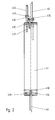
Un exemple de colonne de mesure selon l'invention comprend un
bâti 2 vertical monté perpendiculairement sur un socle 20. Le bâti est creux
et comprend une face avant munie d'une règle non représentée et de rails
de guidage 24. La règle est munie d'électrodes capacitives ou magnétiques,
par exemple, permettant une mesure de position absolue ou relative au
moyen d'un capteur non représenté monté sur le chariot 3. Les rails 24
peuvent être rapportés ou de préférence usinés sur bâti 2 et constituent
une surface d'appui plane sur laquelle se déplacent des roulements du
chariot 3. D'autres rails sur une face arrière du bâti 2 forment une surface
de roulement arrière pour des roulements supplémentaires.An example of a measurement column according to the invention comprises a
Un mécanisme d'entraínement motorisé lié au bâti comprend
une poulie supérieure 42 et une poulie inférieure non représentée. Le
mécanisme d'entraínement comprend en outre un moteur permettant
d'entraíner en rotation la poulie supérieure 42, ainsi qu'un câble ou une
courroie d'entraínement 40 formant une boucle tendue entre les deux
poulies. Le chariot 3 est fixé sur le premier brin de la courroie
d'entraínement 40 et peut ainsi être entraíné selon l'axe vertical z au
moyen du moteur. Le contrepoids 41 fixé sur l'autre brin de la courroie
d'entraínement 40 se déplace en sens opposé au chariot 3 à l'intérieur du
bâti 2. La force de traction de la courroie 40 est contrôlée avec précision par
exemple au moyen d'une friction entre le moteur et la poulie
d'entraínement, et/ou en contrôlant le couple d'entraínement du moteur.A motorized drive mechanism linked to the frame comprises
an
Une touche 44 est montée sur le chariot 3 au moyen d'un porte-touche
45. L'extrémité sphérique de la touche 44 est destinée à être mise
en contact avec la pièce à mesurer. Un système de mesure de type capacitif,
inductif, optoélectronique ou magnétorésistif permet d'indiquer sur un
affichage électronique non représenté la position de la touche 44 ou le
déplacement effectué par la touche 44 entre deux points de mesure. Le
système de mesure comporte par exemple un capteur électronique monté
sur le chariot 3 en regard de la règle 22 et relié par une natte de câble
souple non représentée, éventuellement par une liaison radio locale, à une
console de commande et d'affichage de mesure.A key 44 is mounted on the
Le contrepoids 41 et les surfaces de guidage du contrepoids sont
représentés plus en détail sur les figures 2 et 3. Dans cet exemple, le
contrepoids 41 est constitué par un cylindre métallique, par exemple un
cylindre d'acier, dont la masse correspond à celle du chariot 3 et des
éléments entraínés en déplacement avec le chariot. Le point d'attache du
contrepoids 41 sur la courroie est parfaitement centré de manière à
garantir la verticalité du contrepoids. Il est souhaitable de limiter la
longueur du contrepoids. Cela permet en effet de réduire le risque de
collisions lorsque le contrepoids n'est pas parfaitement vertical, et d'autre
part d'augmenter la course possible pour une auteur de bâti possible. Dans
ce but, le diamètre du contrepoids est de préférence proche du diamètre
maximal qui peut être introduit dans le creux du bâti 2.The
A l'arrêt, le contrepoids 41 et le chariot 3 sont ainsi pendus de
chaque côté de la poulie supérieure 42 ; les masses sont en équilibre en
sorte que la courroie d'entraínement 40 n'exerce aucun couple sur cette
poulie. Les masses égales du contrepoids et du chariot sont suffisantes pour
que la courroie d'entraínement 40 ne glisse pas sur la poulie
d'entraínement 42. Des masses importantes provoquent néanmoins des
forces et des moments sur le chariot qui pourraient perturber la mesure.
Dans le cas d'une courroie en matière plastique composite et d'une surface
d'entraínement de la poulie en aluminium éloxé, des essais concluants ont
été effectués avec des masses de l'ordre de 950 grammes. D'autres essais
concluants ont été effectués avec une courroie en acier.When stopped, the
Le contrepoids 41 est muni de deux joints caoutchouc (o-ring) 410
légèrement en saillie sur sa surface externe. Ces joints agissent comme une
surface d'amortissement pour amortir les éventuelles collisions qui peuvent
néanmoins se produire entre le contrepoids et la surface de guidage. Les
oscillations provoquées par ces collisions sont ainsi plus rapidement
amorties et le bruit du choc, amplifié par le tube 26, est assourdi grâce au
caoutchouc. On prévoira de préférence plusieurs joints o-rings en haut et
en bas du contrepoids41 lorsque la longueur de ce dernier est importante
et qu'il pourrait se déplacer de manière légèrement oblique.
La courroie 40 est fixée à l'extrémité inférieure du contrepoids 41
au moyen d'une vis sans tête 411 ou d'une goupille maintenant la courroie
dans une fente 416. Un dispositif de réglage de la tension de la courroie 40
est prévu à l'autre extrémité du contrepoids 41. Sur l'exemple illustré, ce
dispositif comprend une vis sans tête 412 vissée et de préférence collée
dans le contrepoids 41. Une équerre 414 coulisse le long de la tige 412 et
dans une fente 417 dans le contrepoids. Grâce à un écrou 413, l'équerre 414
peut être rapprochée du contrepoids 41 de manière à tendre la courroie
qui est fixée contre l'équerre au moyen d'une vis 415.The
Sur l'exemple représenté, les surfaces de guidage du contrepoids
41 sont constituées par la face interne 260 d'un tube cylindrique 26 monté
à l'intérieur du bâti 2. Comme indiqué plus haut, le jeu entre le rayon
maximal du contrepoids - au niveau du joint o-ring 410 et la surface
interne du tube de guidage est de préférence compris entre 0.2 et 5
millimètres, préférablement entre 0.5 et 2.0 millimètres, par exemple 1
millimètre. La longueur du tube de guidage est égale ou supérieure à la
course du contrepoids et dépend donc de la hauteur de la colonne de
mesure.In the example shown, the guide surfaces of the
Le tube de guidage 26 est monté dans le bâti 2 au moyen de vis
261. Dans l'exemple illustré, 3 vis 261 sont disposées près du sommet du
tube et 3 vis supplémentaires près de sa base. Ces vis sont dotées de
rondelles élastiques bombées 262 et permettent d'ajuster la verticalité du
tube 26 dans les deux axes, de manière à assurer un déplacement du
contrepoids 41 sans collisions tout au long de sa course. Les vis réglées sont
de préférence bloquées à l'aide d'un point de colle ou de frein filet. Il serait
aussi possible d'utiliser un nombre d'éléments de réglage de la
perpendicularité différent, par exemple deux vis au sommet et à la base de
la colonne. La verticalité du bâti 2 peut elle-même être ajustée au
préalable, par exemple en réglant le parallélisme entre le socle 20 et le plan
de travail à l'aide de pieds ajustables (non représentés), ou de préférence
en adaptant la perpendicularité entre le socle 20 et le bâti 2 à l'aide de vis
de réglage sous l'assise du socle.The
Dans l'exemple illustré, la section du contrepoids est ronde et il
est guidé par les surfaces internes d'un tube cylindrique 26. Cette
disposition a l'avantage d'utiliser des formes extrudées ou tournées peu
coûteuses à usiner avec précision. On comprendra néanmoins que d'autres
formes de contrepoids, par exemple des contrepoids avec des sections
rectangulaires ou ovales, et de surfaces de guidage peuvent être
employées, des sections non rondes ayant l'avantage d'empêcher la
rotation du contrepoids sur son axe longitudinal. Il est aussi possible de
prévoir des surfaces de guidage qui n'entourent pas tout le contrepoids.
Par exemple, on pourrait employer une ou plusieurs bandes ou tiges
verticales présentant des surfaces de guidage réduites à des lignes, ou
même des points de guidage discrets le long de la course du contrepoids,
par exemple plusieurs vis dans le bâti. Ces variantes ont toutefois
l'inconvénient de nécessiter un réglage et un alignement de chaque point
ou surface de guidage, ce qui renchérit le montage. Par ailleurs, un nombre
de tiges ou de points importants doit être prévu pour empêcher tout
balancement dans toutes les directions possibles le long de la course du
contrepoids.In the example shown, the counterweight section is round and it
is guided by the internal surfaces of a
Dans une variante, il serait également possible d'utiliser des
surfaces du bâti 2, par exemple les surfaces internes de ce bâti, pour guider
le contrepoids. Cette variante a toutefois l'inconvénient de nécessiter un
usinage précis et coûteux de cette pièce relativement massive. La précision
de la mesure dépendant pour une part importante de la rigidité du bâti, ce
dernier est souvent fabriqué en fonte, et donc difficile à usiner avec
précision.Alternatively, it would also be possible to use
surfaces of the
Le contrepoids pourrait aussi être muni d'une ou plusieurs ouvertures longitudinales et être guidé par une ou plusieurs tiges verticales liées au bâti et traversant ces ouvertures avec un jeu. L'usinage de ces ouvertures renchérit toutefois la construction. De surcroít, il est difficile de placer des surfaces d'amortissement, par exemple des joints caoutchouc, à l'intérieur des ces ouvertures.The counterweight could also have one or more longitudinal openings and be guided by one or more vertical rods linked to the frame and crossing these openings with a clearance. The machining of these openings, however, makes construction more expensive. In addition, it is difficult to place cushioning surfaces, for example rubber seals, to inside these openings.
On comprendra enfin qu'il est possible d'utiliser plusieurs contrepoids pendus l'un à côté de l'autre ou l'un sous l'autre, et/ou de relier le chariot avec le ou les contrepoids au moyen de plusieurs câbles ou courroies.We will finally understand that it is possible to use several counterweights hung one beside the other or one under the other, and / or connect the carriage with the counterweight (s) using several cables, or belts.
Claims (13)
Priority Applications (6)
| Application Number | Priority Date | Filing Date | Title |
|---|---|---|---|
| DE60126295T DE60126295T2 (en) | 2001-12-12 | 2001-12-12 | Column for measuring longitudinal dimensions |
| EP01811218A EP1319922B1 (en) | 2001-12-12 | 2001-12-12 | Column for measuring longitudinal dimensions |
| US10/314,717 US6802135B2 (en) | 2001-12-12 | 2002-12-09 | Column for measuring longitudinal dimensions |
| CNB021561508A CN1267695C (en) | 2001-12-12 | 2002-12-11 | Measuring column for longitudinal size |
| JP2002360198A JP3751939B2 (en) | 2001-12-12 | 2002-12-12 | Column for length measurement |
| HK03106964A HK1054784A1 (en) | 2001-12-12 | 2003-09-26 | Column for measuring longitudinal dimensions |
Applications Claiming Priority (1)
| Application Number | Priority Date | Filing Date | Title |
|---|---|---|---|
| EP01811218A EP1319922B1 (en) | 2001-12-12 | 2001-12-12 | Column for measuring longitudinal dimensions |
Publications (2)
| Publication Number | Publication Date |
|---|---|
| EP1319922A1 true EP1319922A1 (en) | 2003-06-18 |
| EP1319922B1 EP1319922B1 (en) | 2007-01-24 |
Family
ID=8184312
Family Applications (1)
| Application Number | Title | Priority Date | Filing Date |
|---|---|---|---|
| EP01811218A Expired - Lifetime EP1319922B1 (en) | 2001-12-12 | 2001-12-12 | Column for measuring longitudinal dimensions |
Country Status (6)
| Country | Link |
|---|---|
| US (1) | US6802135B2 (en) |
| EP (1) | EP1319922B1 (en) |
| JP (1) | JP3751939B2 (en) |
| CN (1) | CN1267695C (en) |
| DE (1) | DE60126295T2 (en) |
| HK (1) | HK1054784A1 (en) |
Families Citing this family (8)
| Publication number | Priority date | Publication date | Assignee | Title |
|---|---|---|---|---|
| EP1241436B1 (en) * | 2001-03-14 | 2014-11-19 | Tesa Sa | Coordinate measuring machine and method for introducing a command to change the measurement mode in this machine |
| CN2765139Y (en) * | 2004-12-27 | 2006-03-15 | 杨忠义 | Double-post digital display height gauge |
| DE602006011792D1 (en) * | 2006-04-18 | 2010-03-04 | Hexagon Metrology Spa | HORIZON ALARM COORDINATE MEASURING MACHINE |
| TWI393855B (en) * | 2007-09-21 | 2013-04-21 | Hon Hai Prec Ind Co Ltd | Lens thickness-measuring device |
| US8167809B2 (en) | 2007-12-20 | 2012-05-01 | Silicon Valley Medical Instruments, Inc. | Imaging probe housing with fluid flushing |
| DE102010017904B4 (en) * | 2010-04-21 | 2013-10-31 | Carl Zeiss Industrielle Messtechnik Gmbh | Coordinate measuring machine with counterweight for a measuring slide |
| CN107195349B (en) * | 2017-05-12 | 2021-05-28 | 中国核电工程有限公司 | Manual emergency mechanism of fuel transfer device |
| CN107860299A (en) * | 2017-11-24 | 2018-03-30 | 张化机(苏州)重装有限公司 | Cradle cylinder body roundness measurement device |
Citations (3)
| Publication number | Priority date | Publication date | Assignee | Title |
|---|---|---|---|---|
| US4149317A (en) * | 1976-03-30 | 1979-04-17 | Fa. C. Stiefelmayer K.G. | Measuring and/or tracing device |
| US5373645A (en) * | 1992-07-16 | 1994-12-20 | Tesa S.A. | Apparatus for the measurement of linear values |
| JPH07253301A (en) * | 1994-03-15 | 1995-10-03 | Nikon Corp | Coordinate measuring apparatus |
Family Cites Families (2)
| Publication number | Priority date | Publication date | Assignee | Title |
|---|---|---|---|---|
| DE3109856C2 (en) * | 1981-03-14 | 1983-01-27 | Mauser-Werke Oberndorf Gmbh, 7238 Oberndorf | Altimeter |
| GB8808283D0 (en) * | 1988-04-08 | 1988-05-11 | Lk Tool Co Ltd | Component control apparatus in measuring machines |
-
2001
- 2001-12-12 EP EP01811218A patent/EP1319922B1/en not_active Expired - Lifetime
- 2001-12-12 DE DE60126295T patent/DE60126295T2/en not_active Expired - Lifetime
-
2002
- 2002-12-09 US US10/314,717 patent/US6802135B2/en not_active Expired - Lifetime
- 2002-12-11 CN CNB021561508A patent/CN1267695C/en not_active Expired - Fee Related
- 2002-12-12 JP JP2002360198A patent/JP3751939B2/en not_active Expired - Fee Related
-
2003
- 2003-09-26 HK HK03106964A patent/HK1054784A1/en not_active IP Right Cessation
Patent Citations (3)
| Publication number | Priority date | Publication date | Assignee | Title |
|---|---|---|---|---|
| US4149317A (en) * | 1976-03-30 | 1979-04-17 | Fa. C. Stiefelmayer K.G. | Measuring and/or tracing device |
| US5373645A (en) * | 1992-07-16 | 1994-12-20 | Tesa S.A. | Apparatus for the measurement of linear values |
| JPH07253301A (en) * | 1994-03-15 | 1995-10-03 | Nikon Corp | Coordinate measuring apparatus |
Non-Patent Citations (1)
| Title |
|---|
| PATENT ABSTRACTS OF JAPAN vol. 1996, no. 02 29 February 1996 (1996-02-29) * |
Also Published As
| Publication number | Publication date |
|---|---|
| US20030106234A1 (en) | 2003-06-12 |
| EP1319922B1 (en) | 2007-01-24 |
| DE60126295D1 (en) | 2007-03-15 |
| HK1054784A1 (en) | 2003-12-12 |
| CN1424557A (en) | 2003-06-18 |
| DE60126295T2 (en) | 2007-10-31 |
| JP3751939B2 (en) | 2006-03-08 |
| CN1267695C (en) | 2006-08-02 |
| US6802135B2 (en) | 2004-10-12 |
| JP2003194502A (en) | 2003-07-09 |
Similar Documents
| Publication | Publication Date | Title |
|---|---|---|
| FR2661346A1 (en) | Moving bed with blocks and mounting plate, particularly for a machine tool | |
| EP1319922B1 (en) | Column for measuring longitudinal dimensions | |
| EP0579961B1 (en) | Measuring apparatus for measuring linear dimensions | |
| FR2601435A1 (en) | PARTICULAR FOOT FOR DISPLAY TERMINALS | |
| EP1319924B1 (en) | Height gauge | |
| EP1319921B1 (en) | Column for measuring a longitudinal dimension | |
| FR2581578A1 (en) | ARRANGEMENT FOR HANDLING OR PLACING SPARE PARTS | |
| FR2874348A1 (en) | CIRCULAR SAW FOR SAWING WOODEN PIECES | |
| FR2674041A1 (en) | RECALL DEVICE IN CENTRAL POINT. | |
| EP2755795A1 (en) | Device for assembling an engine and method for assembling and monitoring such assembly device | |
| FR2777270A1 (en) | BEARING DEVICE, IN PARTICULAR FOR LIFTING DEVICES | |
| FR2743856A1 (en) | DEVICE FOR ANGULAR POSITIONING OF A MASS WITH RESPECT TO A HORIZONTAL SUPPORT AXIS AND LIGHTING APPARATUS PROVIDED WITH SUCH A DEVICE | |
| FR3130370A1 (en) | Angle Calibration System | |
| EP0626559B1 (en) | Concentricity verifying apparatus | |
| FR2937731A1 (en) | Flexion characterization testing apparatus for flexible and mechanically resistant large sized laboratory specimen in aeronautical application, has adjustment and fixation units to adjust position of specimen with respect to support unit | |
| BE1014582A3 (en) | Carriage for milling, drilling or sawing device, has mechanism for altering position of guide devices independently from locking mechanism used to fix these devices in working position | |
| FR2542080A1 (en) | Device for measuring horizontal slopes on an article | |
| FR2901261A1 (en) | Load e.g. heavy load, handling apparatus for industry, has vertical plane passing through structure axis forming angle with plane passing through center of gravity of winch and suspension point to form angle for reducing torsional moment | |
| FR2770645A1 (en) | Tensile especially creep testing machine with specimen alignment seating elements | |
| EP0793609A1 (en) | Speed limiter for cases or pallets carrying various loads and which are gravity displaceable on an inclined plane of rollers or wheels | |
| FR3016620A1 (en) | PALONNIER SUITABLE FOR PRECISE POSITIONING, ON A FIXED PART, OF A SESPENDED WEIGHTED PIECE, IN PARTICULAR BY ROTATION AROUND A HORIZONTAL AXIS. | |
| FR2623785A1 (en) | Device for unwinding and/or winding a reel | |
| FR3126884A1 (en) | Gymnastic springboard with adjustable elasticity | |
| LU83812A1 (en) | DEVICE FOR ADJUSTING THE DEPTH OF CUT OF A FLOOR SAW | |
| FR2575974A1 (en) | DEVICE FOR BALANCING GRADED RULES IN A DEVICE WITH UNIVERSAL PARALLEL RULES |
Legal Events
| Date | Code | Title | Description |
|---|---|---|---|
| PUAI | Public reference made under article 153(3) epc to a published international application that has entered the european phase |
Free format text: ORIGINAL CODE: 0009012 |
|
| AK | Designated contracting states |
Designated state(s): AT BE CH CY DE DK ES FI FR GB GR IE IT LI LU MC NL PT SE TR |
|
| AX | Request for extension of the european patent |
Extension state: AL LT LV MK RO SI |
|
| RAP1 | Party data changed (applicant data changed or rights of an application transferred) |
Owner name: TESA SA |
|
| 17P | Request for examination filed |
Effective date: 20031108 |
|
| AKX | Designation fees paid |
Designated state(s): CH DE FR GB LI |
|
| 17Q | First examination report despatched |
Effective date: 20050520 |
|
| GRAP | Despatch of communication of intention to grant a patent |
Free format text: ORIGINAL CODE: EPIDOSNIGR1 |
|
| GRAS | Grant fee paid |
Free format text: ORIGINAL CODE: EPIDOSNIGR3 |
|
| GRAA | (expected) grant |
Free format text: ORIGINAL CODE: 0009210 |
|
| AK | Designated contracting states |
Kind code of ref document: B1 Designated state(s): CH DE FR GB LI |
|
| REG | Reference to a national code |
Ref country code: GB Ref legal event code: FG4D Free format text: NOT ENGLISH |
|
| REG | Reference to a national code |
Ref country code: CH Ref legal event code: EP |
|
| REF | Corresponds to: |
Ref document number: 60126295 Country of ref document: DE Date of ref document: 20070315 Kind code of ref document: P |
|
| REG | Reference to a national code |
Ref country code: CH Ref legal event code: NV Representative=s name: PATENTS & TECHNOLOGY SURVEYS SA |
|
| GBT | Gb: translation of ep patent filed (gb section 77(6)(a)/1977) |
Effective date: 20070502 |
|
| PLBE | No opposition filed within time limit |
Free format text: ORIGINAL CODE: 0009261 |
|
| STAA | Information on the status of an ep patent application or granted ep patent |
Free format text: STATUS: NO OPPOSITION FILED WITHIN TIME LIMIT |
|
| 26N | No opposition filed |
Effective date: 20071025 |
|
| REG | Reference to a national code |
Ref country code: CH Ref legal event code: PFA Owner name: TESA SA Free format text: TESA SA#RUE DU BUGNON 38#1020 RENENS (CH) -TRANSFER TO- TESA SA#RUE DU BUGNON 38#1020 RENENS (CH) |
|
| PGFP | Annual fee paid to national office [announced via postgrant information from national office to epo] |
Ref country code: GB Payment date: 20141219 Year of fee payment: 14 |
|
| PGFP | Annual fee paid to national office [announced via postgrant information from national office to epo] |
Ref country code: FR Payment date: 20141219 Year of fee payment: 14 |
|
| GBPC | Gb: european patent ceased through non-payment of renewal fee |
Effective date: 20151212 |
|
| REG | Reference to a national code |
Ref country code: FR Ref legal event code: ST Effective date: 20160831 |
|
| PG25 | Lapsed in a contracting state [announced via postgrant information from national office to epo] |
Ref country code: GB Free format text: LAPSE BECAUSE OF NON-PAYMENT OF DUE FEES Effective date: 20151212 |
|
| PG25 | Lapsed in a contracting state [announced via postgrant information from national office to epo] |
Ref country code: FR Free format text: LAPSE BECAUSE OF NON-PAYMENT OF DUE FEES Effective date: 20151231 |
|
| PGFP | Annual fee paid to national office [announced via postgrant information from national office to epo] |
Ref country code: DE Payment date: 20191210 Year of fee payment: 19 |
|
| PGFP | Annual fee paid to national office [announced via postgrant information from national office to epo] |
Ref country code: CH Payment date: 20191219 Year of fee payment: 19 |
|
| REG | Reference to a national code |
Ref country code: DE Ref legal event code: R119 Ref document number: 60126295 Country of ref document: DE |
|
| REG | Reference to a national code |
Ref country code: CH Ref legal event code: PL |
|
| PG25 | Lapsed in a contracting state [announced via postgrant information from national office to epo] |
Ref country code: DE Free format text: LAPSE BECAUSE OF NON-PAYMENT OF DUE FEES Effective date: 20210701 Ref country code: CH Free format text: LAPSE BECAUSE OF NON-PAYMENT OF DUE FEES Effective date: 20201231 Ref country code: LI Free format text: LAPSE BECAUSE OF NON-PAYMENT OF DUE FEES Effective date: 20201231 |