EP1320496B1 - Product dispenser - Google Patents
Product dispenser Download PDFInfo
- Publication number
- EP1320496B1 EP1320496B1 EP01968562A EP01968562A EP1320496B1 EP 1320496 B1 EP1320496 B1 EP 1320496B1 EP 01968562 A EP01968562 A EP 01968562A EP 01968562 A EP01968562 A EP 01968562A EP 1320496 B1 EP1320496 B1 EP 1320496B1
- Authority
- EP
- European Patent Office
- Prior art keywords
- dispenser
- base
- cover
- product
- landing
- Prior art date
- Legal status (The legal status is an assumption and is not a legal conclusion. Google has not performed a legal analysis and makes no representation as to the accuracy of the status listed.)
- Expired - Lifetime
Links
Images


Classifications
-
- B—PERFORMING OPERATIONS; TRANSPORTING
- B65—CONVEYING; PACKING; STORING; HANDLING THIN OR FILAMENTARY MATERIAL
- B65D—CONTAINERS FOR STORAGE OR TRANSPORT OF ARTICLES OR MATERIALS, e.g. BAGS, BARRELS, BOTTLES, BOXES, CANS, CARTONS, CRATES, DRUMS, JARS, TANKS, HOPPERS, FORWARDING CONTAINERS; ACCESSORIES, CLOSURES, OR FITTINGS THEREFOR; PACKAGING ELEMENTS; PACKAGES
- B65D83/00—Containers or packages with special means for dispensing contents
- B65D83/04—Containers or packages with special means for dispensing contents for dispensing annular, disc-shaped, or spherical or like small articles, e.g. tablets or pills
- B65D83/0445—Containers or packages with special means for dispensing contents for dispensing annular, disc-shaped, or spherical or like small articles, e.g. tablets or pills all the articles being stored in individual compartments
- B65D83/0454—Containers or packages with special means for dispensing contents for dispensing annular, disc-shaped, or spherical or like small articles, e.g. tablets or pills all the articles being stored in individual compartments the whole forming a circular container with rotating parts
-
- B—PERFORMING OPERATIONS; TRANSPORTING
- B65—CONVEYING; PACKING; STORING; HANDLING THIN OR FILAMENTARY MATERIAL
- B65D—CONTAINERS FOR STORAGE OR TRANSPORT OF ARTICLES OR MATERIALS, e.g. BAGS, BARRELS, BOTTLES, BOXES, CANS, CARTONS, CRATES, DRUMS, JARS, TANKS, HOPPERS, FORWARDING CONTAINERS; ACCESSORIES, CLOSURES, OR FITTINGS THEREFOR; PACKAGING ELEMENTS; PACKAGES
- B65D83/00—Containers or packages with special means for dispensing contents
- B65D83/04—Containers or packages with special means for dispensing contents for dispensing annular, disc-shaped, or spherical or like small articles, e.g. tablets or pills
- B65D83/0409—Containers or packages with special means for dispensing contents for dispensing annular, disc-shaped, or spherical or like small articles, e.g. tablets or pills the dispensing means being adapted for delivering one article, or a single dose, upon each actuation
-
- H—ELECTRICITY
- H01—ELECTRIC ELEMENTS
- H01M—PROCESSES OR MEANS, e.g. BATTERIES, FOR THE DIRECT CONVERSION OF CHEMICAL ENERGY INTO ELECTRICAL ENERGY
- H01M50/00—Constructional details or processes of manufacture of the non-active parts of electrochemical cells other than fuel cells, e.g. hybrid cells
- H01M50/20—Mountings; Secondary casings or frames; Racks, modules or packs; Suspension devices; Shock absorbers; Transport or carrying devices; Holders
- H01M50/204—Racks, modules or packs for multiple batteries or multiple cells
- H01M50/207—Racks, modules or packs for multiple batteries or multiple cells characterised by their shape
- H01M50/216—Racks, modules or packs for multiple batteries or multiple cells characterised by their shape adapted for button or coin cells
-
- B—PERFORMING OPERATIONS; TRANSPORTING
- B65—CONVEYING; PACKING; STORING; HANDLING THIN OR FILAMENTARY MATERIAL
- B65D—CONTAINERS FOR STORAGE OR TRANSPORT OF ARTICLES OR MATERIALS, e.g. BAGS, BARRELS, BOTTLES, BOXES, CANS, CARTONS, CRATES, DRUMS, JARS, TANKS, HOPPERS, FORWARDING CONTAINERS; ACCESSORIES, CLOSURES, OR FITTINGS THEREFOR; PACKAGING ELEMENTS; PACKAGES
- B65D2313/00—Connecting or fastening means
- B65D2313/04—Connecting or fastening means of magnetic type
-
- B—PERFORMING OPERATIONS; TRANSPORTING
- B65—CONVEYING; PACKING; STORING; HANDLING THIN OR FILAMENTARY MATERIAL
- B65D—CONTAINERS FOR STORAGE OR TRANSPORT OF ARTICLES OR MATERIALS, e.g. BAGS, BARRELS, BOTTLES, BOXES, CANS, CARTONS, CRATES, DRUMS, JARS, TANKS, HOPPERS, FORWARDING CONTAINERS; ACCESSORIES, CLOSURES, OR FITTINGS THEREFOR; PACKAGING ELEMENTS; PACKAGES
- B65D2313/00—Connecting or fastening means
- B65D2313/10—Adhesive or cohesive means for holding the contents attached to the container
-
- B—PERFORMING OPERATIONS; TRANSPORTING
- B65—CONVEYING; PACKING; STORING; HANDLING THIN OR FILAMENTARY MATERIAL
- B65D—CONTAINERS FOR STORAGE OR TRANSPORT OF ARTICLES OR MATERIALS, e.g. BAGS, BARRELS, BOTTLES, BOXES, CANS, CARTONS, CRATES, DRUMS, JARS, TANKS, HOPPERS, FORWARDING CONTAINERS; ACCESSORIES, CLOSURES, OR FITTINGS THEREFOR; PACKAGING ELEMENTS; PACKAGES
- B65D2583/00—Containers or packages with special means for dispensing contents
- B65D2583/04—For dispensing annular, disc-shaped or spherical or like small articles or tablets
- B65D2583/0472—For dispensing annular, disc-shaped or spherical or like small articles or tablets characterised by the dispensing action
- B65D2583/0477—For dispensing annular, disc-shaped or spherical or like small articles or tablets characterised by the dispensing action the container is maintained in the same position during the dispensing of several successive articles or doses
- B65D2583/0481—One reciprocating action, e.g. to or from
-
- H—ELECTRICITY
- H01—ELECTRIC ELEMENTS
- H01M—PROCESSES OR MEANS, e.g. BATTERIES, FOR THE DIRECT CONVERSION OF CHEMICAL ENERGY INTO ELECTRICAL ENERGY
- H01M12/00—Hybrid cells; Manufacture thereof
- H01M12/04—Hybrid cells; Manufacture thereof composed of a half-cell of the fuel-cell type and of a half-cell of the primary-cell type
- H01M12/06—Hybrid cells; Manufacture thereof composed of a half-cell of the fuel-cell type and of a half-cell of the primary-cell type with one metallic and one gaseous electrode
-
- Y—GENERAL TAGGING OF NEW TECHNOLOGICAL DEVELOPMENTS; GENERAL TAGGING OF CROSS-SECTIONAL TECHNOLOGIES SPANNING OVER SEVERAL SECTIONS OF THE IPC; TECHNICAL SUBJECTS COVERED BY FORMER USPC CROSS-REFERENCE ART COLLECTIONS [XRACs] AND DIGESTS
- Y02—TECHNOLOGIES OR APPLICATIONS FOR MITIGATION OR ADAPTATION AGAINST CLIMATE CHANGE
- Y02E—REDUCTION OF GREENHOUSE GAS [GHG] EMISSIONS, RELATED TO ENERGY GENERATION, TRANSMISSION OR DISTRIBUTION
- Y02E60/00—Enabling technologies; Technologies with a potential or indirect contribution to GHG emissions mitigation
- Y02E60/10—Energy storage using batteries
Definitions
- the present invention relates to a dispenser for housing and dispensing product, such as miniature batteries including zinc air cells used in hearing aids.
- product such as miniature batteries including zinc air cells used in hearing aids.
- battery means one or more cells.
- Handling of miniature batteries is difficult because of their small size. Handling of miniature batteries is typically required in order to remove the batteries from their packaging, to insert the batteries in the proper orientation into a device, and, in the case of air cells, to remove any individual tabbing associated with the cell prior to use. Tabbing is normally associated with metal air cells such as zinc air cells, to limit the ingress of oxygen into the cell until such time as the cell is placed into service.
- the tab also functions to limit the transport of water vapor in or out of the cell and limits the ingress of carbon dioxide into the cell. Typically, the tab comprises an adhesive material covering one or more air ports. Upon removal of the tab, the ports are exposed to the oxygen of the ambient environment, thereby enabling the cell to be activated. The challenge of handling miniature batteries is exacerbated in the event the user suffers from reduced dexterity, poor vision or other physical infirmity.
- U.S. Pat. No. 6,039,185 discloses a device for inserting a hearing aid battery into a hearing aid.
- the device comprises so-called "petals" with an air cell residing on each petal.
- the cells are individually tabbed, and each tab is then adhered to the petal.
- the cell is inserted into the hearing aid by gripping the inserter and bringing the appropriate petal up close to the hearing aid battery door to enable the cell to be engaged within the door.
- the cell is then separated from the inserter using a wiping motion, purportedly leaving the tab adhered to the petal.
- the method of separating the cell from its associated tab and the inserter as disclosed in the '185 patent places stresses on the hearing aid device, presenting the potential for damage to the device.
- Typical packaging for miniature zinc air cells presents further problems.
- Common packaging for miniature zinc air cells is disclosed for example in US Pat. No. 4,953,700.
- the packaging disclosed therein consists of a thermoformed or molded blister rotatably attached to a paperboard card.
- the blister comprises multiple compartments each containing a battery.
- a battery is dispensed from the package by rotating the blister to align a loaded compartment with a trap door accessible in the back of the card.
- the trap door can come open during transport and batteries will fall out.
- the trap door becomes weak and ineffective after multiple uses.
- the base of the dial can also separate or pull away from the card allowing batteries to fall out.
- the consumer must still handle the battery to remove the tab, properly orient the cell in connection with the device terminals and insert the cell into the device once the battery has been removed from the package.
- This tool consists of a magnet on the end of a wand.
- the tool can be easily misplaced and provides little aid in removing the individual tabbing associated with common zinc air cells.
- Another object of the present invention is to provide a product dispenser that eliminates the need for additional tools to handle and orient product for insertion or placement for end use.
- Another object of the present invention is to provide a product dispenser that avoids unintended dispensing from the dispenser.
- Another object of the present invention is to provide a refill base cartridge for a product dispenser.
- Another object of the present invention is to provide a product dispenser that optionally allows the user to attach a refill base after removal of a spent base cartridge.
- Another object of the present invention is to provide a product dispenser that allows the consumer to store used product for disposal or material recovery purposes.
- the present invention provides for a product dispenser that is easy to use for storing and dispensing product, such as miniature batteries.
- the dispenser of the within invention obviates the need to handle the product at any point during the dispensing process or during the insertion or placement process of the product for its end use.
- the present invention provides for a product dispenser according to claim 1.
- the cover further comprises a rib.
- the rib is secured to the inner surface of the roof such that when the cover is assembled with the base, the product is under pressure from the rib allowing the rib to further secure the product to the base during transport and storage.
- the rib functions to apply pressure so as to seal an air cell to a gasket prior to dispensing.
- the cover is removably attached to the base allowing the base to be disposed of and a replacement base with additional product to be joined with the cover.
- the bottom side of the base comprises a storage area for storing used product for disposal or material recovery purposes.
- the entire dispenser could be processed for material recovery or otherwise recycled.
- the base alone could be processed for material recovery or otherwise recycled.
- the cover is made of see-through material and the push element or base or both can be color coded to indicate various product characteristics, such as size.
- the dispenser 10 of the within invention comprises a cover 12, a retractable push element 14, and a base 16.
- the cover 12 and the base 16 are connected such that each can be rotated about a common axis with respect to the other. That is, the cover can be rotated while maintaining the base in a stationary position, or, conversely, the base can be rotated while maintaining the cover in a stationary position.
- the rotatable cover 12 comprises a roof 121, roof ramps 122, a roof opening 123, a wall 124, a wall opening 125, a landing 126, and flexible snap-hook connectors 127a, 127b and 127c.
- the cover 12 is made from a readily-available, polycarbonate-based material such as Lexan® 143R resin manufactured by GE Plastics and available from Polymerland Service Center, Pittsburgh, PA 15264. It should be appreciated that other durable materials may be used in producing the cover 12.
- the cover 12 may further include a rib 128 as shown in figure 2C.
- the roof ramps 122 protrude from the outer surface 129 of the roof 121 adjacent to the roof opening 123.
- the roof ramps 122 are angled protrusions that frictionally engage the push element 14 and create a transitional stopping action for the push element as it is extended.
- the ramps 122 aid in providing a fluid and controlled motion for the push element 14 that encourages controlled movement of product toward the landing 126.
- the ramps 122 also aid in maintaining the push element in a fully extended position.
- a third roof ramp 122a may be positioned on the outer surface 129 of the roof 121 such that the third roof ramp aids in keeping the push element in place while fully retracted. It will be appreciated that a wide variety of shapes and locations can be utilized for the roof ramps without departing from the teachings of the within invention.
- the roof opening 123 is coincidental with the wall opening 125 and the landing 126 is secured to the cover 12 at a location adjacent to the wall opening 125.
- Product passes through the wall opening 125 from the interior of the cover 12 onto the landing 126.
- Product aligned at the wall opening 125 for such transition is said to be located in the product dispensing position.
- the landing 126 is preferably inclined as shown in Figure 4B to further aid in transitioning the product from the interior of the cover 12 to the landing 126.
- the landing 126 optionally comprises a magnetic component 130 secured to the landing 126 via a pressure sensitive adhesive.
- the magnetic component 130 aids in controlling and removably maintaining metallic products such as miniature batteries on the landing 126.
- other surfaces or materials such as velcro or adhesives, may be utilized for controlling and removably maintaining products on the landing 126 as will be appreciated by those skilled in the art. These alternate surfaces or materials may comprise the entire landing 126 or may be secured to the landing 126 via an adhesive or other securing method.
- the magnetic component 130 can be planar or otherwise shaped, and may be exposed or embedded within the landing.
- the landing 126 may further include a stop wall (not shown) at its distal end to further control the forward motion of the product as it transitions from the interior of the cover 12 to the landing 126. It should be appreciated that the landing 126 may be integral to the cover 12 or the base 16 or may be a separate component connected to either the cover 12 or the base 16.
- the snap hook connectors 127a, 127b and 127c extend from the inner surface of the roof 121 and are positioned at 90 degree intervals around the roof opening 123.
- the connectors further comprise flexible angled lead-in surfaces 131 and flexible tension-providing surfaces 132.
- the lead-in surfaces 131 interact with the inner surface of the base opening during connection of the base with the cover, causing the snap hook connectors to flex inwardly, as will be more fully explained below.
- the tension-providing surfaces 132 maintain tension contact with the base upon completion of the connection process and the outward return flex of the snap hook connectors 127a, 127b and 127c.
- the number and positioning of the snap hook connectors is a matter of design choice and can be varied without departing from the scope of the within invention.
- One of the snap hook connectors further comprises a rib 133.
- the rib 133 is positioned such that when the cover 12 or the base 16 is rotated, a stop point is created once the rib 133 engages a base turret groove 173. Each such stop point aligns a product and/or a product dispensing position with the wall opening 125 of the cover 12.
- the outer surface of the cover wall 124 may be all or partially ribbed as illustrated or otherwise textured to provide a grip for the cover 12 during relative motion between the cover 12 and base 16. Additional gripping can be provided by extending the upper surface of the cover 12 outwardly beyond the cover wall 124 at one or more locations.
- the push element 14 comprises a thumbpiece 141 having gripping ribs 142 or alternatively a textured surface secured to the upper surface of the thumbpiece 141 for gripping the push element 14.
- the push element is molded from a polystyrene material such as Styron 6075 manufactured by Dow Plastics and available from General Polymers, Columbus, OH 43216.
- the push element 14 further comprises a projection 143.
- the projection 143 extends over at least a portion of the product located in the product dispensing position during transport and storage of the dispenser 10, to aid in maintaining the product in this position.
- the projection 143 further aids in controlling the movement ofproduct during transition from the interior of the cover 12 onto the landing 126, and in maintaining the position of individual product on the landing 126.
- a lip 144 is located on the bottom surface of the projection 143 which aids in securing individual product in the product dispensing position and in position on the landing 126.
- the push element 14 further comprises two slide rails 145 and a center rudder 146, both secured to the lower surface of the thumbpiece 141.
- the rudder 146 is aligned with a base turret opening 172 whenever the snap hook connector rib 133 is engaged with a base turret groove 173 to create a stop position for relative motion between the cover 12 and the base 16. Such alignment is required to allow the push element to be extended.
- the rudder 146 does not occupy the aligned base turret opening 172 and the base 16 and the cover 12 are free to move with respect to each other between stop positions. This fully retracted position will be referred to herein as the first position of the push element 14.
- the push element 14 can be partially or fully extended, causing the rudder 146 to occupy the aligned base turret opening 172 thereby preventing motion between the base 16 and the cover 12 to an alternate stop position.
- This partial or full extension position will be referred to herein as the second position of the push element 14.
- the rudder 146 further comprises a scraper 147 positioned at the front of the rudder.
- the scraper 147 is designed to separate individual product from the product dispensing position by interposing the scraper 147 between the product and the product dispensing position upon extension of the thumbpiece 141. In the case of an air cell, interposing the scraper 147 between the cell and the product dispensing position untabs the cell, allowing air ingress and cell activation.
- the projection 143, the lip 144 and the scraper 147 may all be contoured to shape according to the product contained within the dispenser without departing from the teachings herein.
- the slide rails 145 of the thumbpiece 141 comprise snap hooks having angled surfaces 148a and flat surfaces 148b.
- the angled surfaces 148a allow a portion of the push element 14 to pass through the roof opening 123 for snap connection of the push element with the cover 12.
- the angled surfaces 148a contact the sides of the roof opening during connection causing the snap hooks to flex inwardly. Once the angled surfaces 148a have cleared the roof opening 123, the snap hooks retract, thereby engaging the inner surface of the cover and the flat surfaces 148b of the snap hooks, enabling the push element to slidably extend and retract along the roof opening 123.
- the push element 14 further comprises two stop walls 149 positioned on the lower surface of the thumbpiece 141.
- the stop walls 149 define a stop position for the fully extended push element 14 upon contacting the inside surface of the cover wall 124.
- the stop position for the fully extended push element 14 can be provided by extending the slide rails 145 so that they contact the inside surface of the cover wall 124 when the push element 14 is fully extended.
- the base 16 comprises a lower tier 161, an upper tier 162 and a hollow center 163.
- the lower tier comprises an outer wall 164 and an upper surface 165.
- the upper tier further comprises an outer wall 166 and an upper surface 167.
- the base is molded from Styron 6075 as described above.
- the lower tier upper surface 165 is sized to accommodate the width of the cover wall 124. When joined, the bottom surface of the cover wall 124 is in contact with the lower tier upper surface 165 and a portion of the inner surface of the cover wall 124 is in contact with the upper tier outer wall 166.
- All or a portion of the lower tier outer wall 164 may be partially ribbed as shown or otherwise textured to provide a grip for the base 16 during relative motion between the cover 12 and base 16. Extensions (not shown) from the base may be included to provide handles to aid in separating the base 16 from the cover 12.
- the lower tier outer wall 164 may optionally include an indicator such as an arrow (not shown). Aligning the landing 126 with the indicator during connection of the cover and base also aligns the snap hook connector rib 133 of the cover 12 with a base turret groove 173, facilitating the connection.
- the hollow center 163 further comprises a turret partition 169 defined by a beveled edge 170 and turret structures 171 extending above the upper tier upper surface 167.
- the turret structures 171 are separated by turret openings 172.
- the openings 172 are sized to permit the rudder 146 to occupy an opening during extension of the push element 14 in its second position.
- the lead in surfaces 131 of the cover snap hook connectors 127a-c contact the turret partition 169 during connection of the cover and base, causing the cover snap hook connectors to flex inwardly.
- the snap hook connectors Upon encountering the beveled edge 170 of the base hollow center 163, the snap hook connectors retract, allowing the tension-providing surfaces 132 of the cover snap hook connectors to contact the beveled edge and thereby secure the cover and base together.
- the turrets 171 further comprise grooves 173 extending along the length of the partition 169. Insertion of the snap hook rib 133 of the cover into one of the turret grooves 173 defines a stop position whereby product located at the product dispensing position is aligned with the cover wall opening 125 and the landing 126.
- the platform comprises at least one adhesive layer.
- the platform comprises a lower adhesive layer 176, a mid adhesive layer 177, an upper adhesive layer 178, a foam tape layer 179 sandwiched between the lower and mid adhesive layers, a mylar film layer 180 sandwiched between the mid and upper adhesive layers, and a polyester overcoat layer 181 located atop the upper adhesive layer.
- the lower and mid adhesive layers with a foam layer sandwiched in between are available as a single product, from Label Technologies Inc., Spec.
- the mylar film layer and upper adhesive layer are also available as a single product from Label Technologies Inc., Spec. #72907 (polyolefin with R-143 adhesive).
- the polyester overcoat layer is available from Label Technologies Inc., Spec. #2216 (interfilm metalized polyester).
- Alternating cutouts 175a are provided in the overcoat layer 181 to expose portions of the underlying adhesive layer 178.
- the air cells 174 are placed upon the exposed adhesive portions to seal their associated air ports until such time as the cell is transferred from the interior of the cover to the landing.
- the cutouts are larger than the diameter of the cells, such that the cells do not come into direct contact with the overcoat layer.
- the overcoat layer 181 is an optional feature designed primarily to prevent the accumulation of dust and other debris on the upper adhesive layer 178 and to provide an aesthetically pleasing appearance. As such, it will be appreciated that other materials with an aesthetically appealing appearance, adequate adhesion to the underlying adhesive layer, and a surface that will avoid the accumulation of dust and debris could be used in place of the polyester overcoat layer 181.
- the air cells are not individually tabbed, thereby obviating the expense associated with such an operation. Further, the tabbing material remains with the dispenser when the cell is dispensed, avoiding the need to handle or otherwise dispose of an individual tab. It will be appreciated, however, that the dispenser of the within invention can be utilized with individually tabbed air cells.
- the tab is mechanically or adhesively joined to the base. The cell is then separated from the tab when the thumbpiece scraper is inserted between the tab and the cell. The cell is then advanced from the interior of the cover onto the landing while the tab remains attached to the dispenser base.
- Adhesive to secure product may be applied as a surface coating to the upper tier upper surface 165, or alternatively, may be applied in discrete locations to coincide with the number and spacing of product on the upper surface of the upper tier.
- Adhesives appropriate to the type of product can be selected as is known in the art.
- the underside of the base 16 optionally comprises a series of support ribs 182.
- the ribs define one or more storage compartments 183 for spent product. Where individual compartments are defined by such ribs, spent product can be secured in position using an interference fit between the product and the storage compartment. Alternatively, spent product can be secured into position by sealing the compartments with a rotatable covering 184 having an opening 185, as illustrated in figures 7a-c. The opening 185 could be aligned with an individual storage compartment to allow the spent air cells to pass through the opening into the compartment 183. In the event support ribs are not utilized, the void volume of the base can still function as a repository for spent product as illustrated in figure 8.
- the push element 14 is placed in the first position, the fully retracted position.
- the cover 12 and base 16 are then rotated with respect to each other until a stop position is reached where product is located in the product dispensing position.
- the push element is then advanced to the fully extended position, causing the product to transition from the product dispensing position to the landing.
- the dispenser 10 may be used as a handle to orient the product and insert it correctly into a device.
- the dispenser 210 of the within invention comprises a cover 212, a retractable push element 214 and a base 216.
- the cover 212 and the base 216 are connected such that each can be rotated about a common axis with respect to the other. That is, the cover can be rotated while maintaining the base in a stationary position, or, conversely, the base can be rotated while maintaining the cover in a stationary position.
- the rotatable cover 212 comprises a roof 321, a roof opening 322, a wall 323, a wall opening 324, a landing 325 and cover snap hook connectors 326.
- the cover 212 can be made from a readily-available, polycarbonate-based material such as Lexan® 143R resin manufactured by GE Plastics and available from Polymerland Service Center, Pittsburgh, PA 15264. It should be appreciated that other durable materials may be used in producing the cover 212.
- the roof opening 322 is coincidental with the wall opening 324 and the landing 325 is secured to the cover 212 at a location adjacent to the wall opening 324.
- Product passes through the wall opening 324 from the interior of the cover 212 onto the landing 325.
- Product aligned at the wall opening 324 for such transition is said to be located in the product dispensing position.
- the landing 325 is preferably inclined as shown to further aid in transitioning the product from the interior of the cover 212 to the landing 325.
- the landing 325 optionally comprises a magnetic component 327 embedded within the landing.
- the magnet can be secured to the landing surface via a pressure sensitive adhesive or otherwise affixed to the landing, as is known in the art.
- the magnetic component 327 aids in controlling and removably maintaining metallic products such as miniature batteries on the landing 325.
- other surfaces or materials, such as velcro or adhesives may be utilized for controlling and removably maintaining products on the landing as will be appreciated by those skilled in the art. These alternate surfaces or materials may comprise the entire landing.
- the magnetic component 327 can be planar or otherwise shaped.
- the landing 325 may further include a stop wall (not shown) at its distal end to further control the forward motion of the product as it transitions from the interior of the cover 212 to the landing 325. It should be appreciated that the landing 325 may be integral to either the cover 212 or the base 216 or may be a separate component connected to either the cover 212 or the base 216.
- the snap hook connectors 326 extend inwardly from the inner surface of the cover 212 and are positioned at regular intervals around the interior perimeter of the cover 212.
- the connectors interact with the base ring 362 during connection of the base ring with the cover as will be more fully explained below and maintain tension contact with the base ring upon completion of the connection process.
- the number, shape and positioning of the snap hook connectors is a matter of design choice and can be varied without departing from the scope of the within invention.
- the outer surface of the cover wall 323 may be all or partially ribbed as illustrated or otherwise textured to provide a grip for the cover 212 during relative motion between the cover 212 and base 216. Additional gripping can be provided by extending the upper surface of the cover 212 outwardly beyond the cover wall 323 at one or more locations.
- the push element 214 comprises a thumbpiece 341 having a gripping rib 342 or alternatively a textured surface secured to the upper surface of the thumbpiece 341 for gripping the push element 214.
- the push element can be molded from a polystyrene material such as Styron 6075 manufactured by Dow Plastics and available from General Polymers, Columbus, OH 43216, or such other suitable material as is known in the art.
- the push element 214 further comprises a projection 343.
- the projection 343 extends over at least a portion of the product located in the product dispensing position during transport and storage of the dispenser 210, to aid in maintaining the product in this position.
- the projection 343 further aids in controlling the movement of product during transition from the interior of the cover 212 onto the landing 325, and in maintaining the position of individual product on the landing 325.
- a lip 344 is located on the bottom surface of the projection 343 which aids in securing individual product in the product dispensing position and in position on the landing 325.
- the push element 214 further comprises two slide rails 345 and a central rudder 346 and two side rudders 346a secured to the lower surface of the thumbpiece 341.
- the push element 214 can be extended to advance product onto the landing 325. Extension of the push element causes the center rudder 346 to occupy a base platform turret opening 367, preventing rotation of the base 216 with respect to the cover 212.
- the rudder 346 When the push element 214 is fully retracted, the rudder 346 does not occupy a base platform turret opening 367 and the base 216 and the cover 212 are free to move with respect to each other, enabling product to be located in the product dispensing position. Movement of the push element 214 is further controlled by upper projections 372 on base ring 362. When the push element is extended to advance product onto the landing 325, side rudders 346a occupy an opening between upper projections 372, thereby preventing rotation of the cover and base with respect to each other.
- the slide rails 345 maintain a snap connection between the push element 214 and the cover 212 and cooperate with the surfaces of the roof opening 322 to allow the push element to move along the roof opening.
- projection 343 and the lip 344 may be contoured to shape according to the product contained within the dispenser without departing from the teachings herein.
- the slide rails 345 comprise snap hooks to provide a snap connection between the push element and the cover 212 while enabling the push element to slidably extend and retract along the roof opening 322.
- the slide rails 345 contact the inside surface of the cover wall 323 preventing further extension and defining the fully extended push element position.
- the base 216 comprises a base platform 361, a base ring 362 and a product platform 363.
- the base platform 361 comprises openings 364 at regularly spaced intervals that cooperate with extensions 365 on the base ring 362 to provide a snap connection between the base platform 361 and the base ring 362.
- the base platform 161 further comprises turret extensions 166 defining turret openings 167 arranged in a concentric circle, to control the movement of the push element 214 as explained above.
- All or a portion of the base platform 361 may be ribbed as shown or otherwise textured to provide a grip for the base 216 during relative motion between the cover 212 and base 216. Extensions (not shown) from the base may be included to provide handles to aid in separating the base 216 from the cover 212.
- the adhesive product platform comprises an adhesive tab layer 368, a kill liner layer 369 and an adhesive foam layer 370.
- the tab layer 368 has an adhesive upper surface and comprises precut tab areas 371. Air cells 400 are positioned onto the adhesive surface at the tab areas 371, thereby preventing the ingress of air sufficient to activate the cells prior to dispensing the cells from the dispenser 210.
- a kill liner layer 369 is positioned between the tab layer 368 and the foam layer 370.
- the function of the kill liner layer 369 is to selectively block the upper adhesive surface of the foam layer 370 from contacting selected portions of the lower surface of the tab layer 368 and is shaped accordingly.
- a mylar film suitable for this function can be selected as is known in the art. In this way only a portion of the precut tab areas 371 are adhesively secured to the foam layer 369 prior to dispensing the cell, enabling a measure of control over the amount of force required to separate the cell from the tab as the cell is advanced by the push element from the interior of the dispenser to the dispenser landing.
- the foam layer and the tab layer are available from Label Technologies, Suwanee, Georgia.
- the kill liner layer can be eliminated by selectively applying an adhesive to only those portions of the upper surface of the foam layer 370 where adhesive contact with the lower surface of the tab layer 368 is desired. In another embodiment, selective application of adhesive is accomplished in only those portions of the upper surface of the tab layer 368 where adhesive contact with the product is desired.
- the product platform 363 is further joined to the base platform 361 via the snap connection between the base ring 362 and the base platform 361.
- the base ring 362 comprises a lip about the perimeter to capture the outer perimeter of the tab layer 368, and lower extensions 365 spaced about the perimeter that cooperate with openings 364 in the base platform to provide a snap connection.
- the base ring 362 further comprises grooves 373 preferentially corresponding in number to the number of product positions in the dispenser. The grooves 373 cooperate with a boss 328 located on a cover snap hook connector 326 to define a stop position during rotation of the base and cover with respect to each other. The stop position effectively aligns the push element 214 with product in the product dispensing position.
- the base ring 362 captures the outer perimeter of the tab layer 368 during assembly of the dispenser, aiding in the separation of the cell from the precut tab areas and in the retention of the precut tab areas with the dispenser as the cell is advanced off of the precut tab areas in transition from the interior of the dispenser to the landing 325.
- the air cells are not individually tabbed with discrete tabs, thereby obviating the expense associated with such an operation. Further, the tabbing material layer remains with the dispenser when the cell is dispensed, avoiding the need to handle or otherwise dispose of an individual tab. It will be appreciated, however, that the dispenser of the within invention can be utilized with individually tabbed air cells.
- the discrete tab is mechanically or adhesively joined to the base. The cell is then separated from the tab when the cell is advanced from the interior of the cover onto the landing while the tab remains attached to the dispenser base.
- Adhesive to secure product may be applied as a surface coating to the upper surface of the base platform 361, or alternatively, may be applied in discrete locations to coincide with the number and spacing of product on the upper surface, thereby obviating the need for discrete adhesive layer 368, kill liner layer 369 and foam adhesive layer 370.
- Adhesives appropriate to the type of product can be selected as is known in the art.
- the dispenser can be reused by discarding all or a portion of the base 216 once all of the product has been completely dispensed.
- a refill kit comprising fresh product to be dispensed using the dispenser on a replacement base 216 is provided for re-introduction into the dispenser for use with the original cover 212 and push element 214.
- additional stability is provided to the push element 214 as it transitions between its fully extended and fully retracted positions by additional grooves 374 positioned on the underside of the push element 214.
- These grooves 374 cooperate with projections 375 positioned on the cover 212. It will be appreciated that the grooves 374 could alternatively be located on the cover 212 and the projections 375 be located on the push element 214 without departing from the scope of the within invention.
- the underside of the base 216 optionally comprises a series of storage compartments (not shown) for spent product.
- Spent product can be secured in position using an interference fit between the product and the storage compartment.
- spent product can be secured into position by sealing the compartments with a rotatable covering (not shown) having an opening aligned with an individual storage compartment to allow the spent air cells to pass through the opening into the compartment.
Abstract
Description
- The present invention relates to a dispenser for housing and dispensing product, such as miniature batteries including zinc air cells used in hearing aids. As used herein, "battery" means one or more cells.
- Handling of miniature batteries is difficult because of their small size. Handling of miniature batteries is typically required in order to remove the batteries from their packaging, to insert the batteries in the proper orientation into a device, and, in the case of air cells, to remove any individual tabbing associated with the cell prior to use. Tabbing is normally associated with metal air cells such as zinc air cells, to limit the ingress of oxygen into the cell until such time as the cell is placed into service. The tab also functions to limit the transport of water vapor in or out of the cell and limits the ingress of carbon dioxide into the cell. Typically, the tab comprises an adhesive material covering one or more air ports. Upon removal of the tab, the ports are exposed to the oxygen of the ambient environment, thereby enabling the cell to be activated. The challenge of handling miniature batteries is exacerbated in the event the user suffers from reduced dexterity, poor vision or other physical infirmity.
- Efforts to address some of these issues are found in the art. For example, U.S. Pat. No. 6,039,185 discloses a device for inserting a hearing aid battery into a hearing aid. The device comprises so-called "petals" with an air cell residing on each petal. The cells are individually tabbed, and each tab is then adhered to the petal. The cell is inserted into the hearing aid by gripping the inserter and bringing the appropriate petal up close to the hearing aid battery door to enable the cell to be engaged within the door. The cell is then separated from the inserter using a wiping motion, purportedly leaving the tab adhered to the petal. The method of separating the cell from its associated tab and the inserter as disclosed in the '185 patent places stresses on the hearing aid device, presenting the potential for damage to the device.
- Typical packaging for miniature zinc air cells presents further problems. Common packaging for miniature zinc air cells is disclosed for example in US Pat. No. 4,953,700. The packaging disclosed therein consists of a thermoformed or molded blister rotatably attached to a paperboard card. The blister comprises multiple compartments each containing a battery. A battery is dispensed from the package by rotating the blister to align a loaded compartment with a trap door accessible in the back of the card. The trap door can come open during transport and batteries will fall out. The trap door becomes weak and ineffective after multiple uses. The base of the dial can also separate or pull away from the card allowing batteries to fall out. Finally, the consumer must still handle the battery to remove the tab, properly orient the cell in connection with the device terminals and insert the cell into the device once the battery has been removed from the package.
- Some consumers use a separate tool to assist them in loading miniature batteries into devices. This tool consists of a magnet on the end of a wand. The tool can be easily misplaced and provides little aid in removing the individual tabbing associated with common zinc air cells.
- Handling of other small products including but not limited to pharmaceuticals such as pills, foodstuff such as candy, hardware such as screws, and the like can be equally difficult because of their size, particularly for those users suffering from reduced dexterity, poor vision or other physical infirmity (see US-A-3 437 236). While the within invention is illustrated in connection with miniature cells, and in particular in connection with miniature zinc air cells, it will be appreciated that the within invention can also be utilized in connection with the transport, storage and dispensing of such other small products. As used herein, the term "product" is not limited to miniature cells or batteries, and fully comprehends such other small products as those identified above.
- It is therefore a first object of the present invention to provide a product dispenser that acts as both a structural package for housing and transporting product and a dispenser for removing product from the package and an inserter for manipulating and orienting product into a device or other end use location.
- It is also an object of the present invention to provide a product dispenser that removes any direct handling of product prior to its insertion into a device or other end use location.
- It is a further object of the present invention to provide a product dispenser that obviates the need for direct handling of tab material in the case of a metal air cell such as a zinc air cell.
- It is a further object of the present invention to provide a product dispenser that both activates and dispenses air cells such that the user does not have to handle the cells either before or after insertion into a device.
- Another object of the present invention is to provide a product dispenser that eliminates the need for additional tools to handle and orient product for insertion or placement for end use.
- Another object of the present invention is to provide a product dispenser that avoids unintended dispensing from the dispenser.
- Another object of the present invention is to provide a refill base cartridge for a product dispenser.
- Another object of the present invention is to provide a product dispenser that optionally allows the user to attach a refill base after removal of a spent base cartridge.
- Another object of the present invention is to provide a product dispenser that allows the consumer to store used product for disposal or material recovery purposes.
- The foregoing and additional objects of this invention will become fully apparent from the following description and the accompanying drawings.
- The present invention provides for a product dispenser that is easy to use for storing and dispensing product, such as miniature batteries. The dispenser of the within invention obviates the need to handle the product at any point during the dispensing process or during the insertion or placement process of the product for its end use. To achieve this and other advantages, and in accordance with the purposes of the present invention as embodied and described herein, the present invention provides for a product dispenser according to claim 1.
- In another embodiment, the cover further comprises a rib. The rib is secured to the inner surface of the roof such that when the cover is assembled with the base, the product is under pressure from the rib allowing the rib to further secure the product to the base during transport and storage. In another embodiment, the rib functions to apply pressure so as to seal an air cell to a gasket prior to dispensing.
- In another embodiment, the cover is removably attached to the base allowing the base to be disposed of and a replacement base with additional product to be joined with the cover.
- In another embodiment the bottom side of the base comprises a storage area for storing used product for disposal or material recovery purposes. The entire dispenser could be processed for material recovery or otherwise recycled. In the event the cover and the base are separable, the base alone could be processed for material recovery or otherwise recycled.
- In another embodiment the cover is made of see-through material and the push element or base or both can be color coded to indicate various product characteristics, such as size.
- These and other features, advantages, and objects of the present invention will be further understood and appreciated by those skilled in the art by reference to the following specification, claims, and appended drawings.
-
- FIGURE 1 is a view of a product dispenser according to the within invention.
- FIGURE 2A is a view of a cover of a product dispenser according to the within invention.
- FIGURE 2B is another view of the cover of Figure 2A.
- FIGURE 2C is a view of an alternate cover of a product dispenser according to the within invention.
- FIGURE 3A is a view of a push element of a product dispenser according to the within invention.
- FIGURE 3B is another view of the push element of Figure 3A.
- FIGURE 3C is a side view of the push element of Figures 3A and 3B.
- FIGURE 4A is a front view of a cover and push element of a product dispenser according to the within invention.
- FIGURE 4B is a section view of the cover and push element of Figure 4A.
- FIGURE 5A is a view of a base of a product dispenser according to the within invention.
- FIGURE 5B is a side view of the base of Figure 5A.
- FIGURE 5C is a section view of the base of Figure 5B.
- FIGURE 5D is another view of the base of Figure 5A.
- FIGURE 6A is a view of a platform of a product dispenser according to the within invention.
- FIGURE 6B is a side view of a platform of a product dispenser according to the within invention.
- FIGURES 7A, 7B and 7C illustrate an alternate base of a product dispenser according to the within invention.
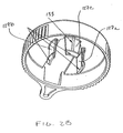
- FIGURE 8 illustrates another alternate base of a product dispenser according to the within invention.
- FIGURE 9 is an exploded view of an alternate embodiment of a product dispenser according to the within invention.
- FIGURE 10A is a view of a cover of the product dispenser of Fig. 9.
- FIGURE 10B is another view of the cover of Fig. 10A.
- FIGURE 11 is a view of a base platform of the product dispenser of Fig. 9.
- FIGURE 12 is a view of one layer of the adhesive product platform of the product dispenser of Fig. 9.
- FIGURE 13A is a view of a push element of the product dispenser of Fig. 9.
- FIGURE 13B is another view of the push element of Fig. 13A.
- FIGURE 14A is a view of a base ring of the product dispenser of Fig. 9.
- FIGURE 14B is another view of the base ring of Fig. 14A.
- FIGURE 15 is a view of the product dispenser of Fig. 9.
- FIGURE 16A is a view of an alternate embodiment of the push element of a product dispenser of Fig. 9.
- FIGURE 16B is another view of the push element of FIG. 16A.
- FIGURE 17A is a view of an alternate embodiment of the cover of a product dispenser of Fig. 9.
- FIGURE 17B is another view of the cover of FIG. 17A.
- The specific embodiments illustrated in the appended drawings and described in the following specification are simply exemplary embodiments of the invention defined in the appended claims. Hence, specific dimensions and physical characteristics relating to specific embodiments disclosed herein are not to be considered as limiting, unless the claims expressly state otherwise.
- The
dispenser 10 of the within invention comprises acover 12, aretractable push element 14, and a base 16. Thecover 12 and the base 16 are connected such that each can be rotated about a common axis with respect to the other. That is, the cover can be rotated while maintaining the base in a stationary position, or, conversely, the base can be rotated while maintaining the cover in a stationary position. - The
rotatable cover 12 comprises aroof 121, roof ramps 122, aroof opening 123, awall 124, a wall opening 125, alanding 126, and flexible snap-hook connectors 127a, 127b and 127c. In a preferred embodiment, thecover 12 is made from a readily-available, polycarbonate-based material such as Lexan® 143R resin manufactured by GE Plastics and available from Polymerland Service Center, Pittsburgh, PA 15264. It should be appreciated that other durable materials may be used in producing thecover 12. In addition, thecover 12 may further include a rib 128 as shown in figure 2C. - The roof ramps 122 protrude from the
outer surface 129 of theroof 121 adjacent to theroof opening 123. The roof ramps 122 are angled protrusions that frictionally engage thepush element 14 and create a transitional stopping action for the push element as it is extended. Theramps 122 aid in providing a fluid and controlled motion for thepush element 14 that encourages controlled movement of product toward thelanding 126. Theramps 122 also aid in maintaining the push element in a fully extended position. Alternatively, a third roof ramp 122a may be positioned on theouter surface 129 of theroof 121 such that the third roof ramp aids in keeping the push element in place while fully retracted. It will be appreciated that a wide variety of shapes and locations can be utilized for the roof ramps without departing from the teachings of the within invention. - The
roof opening 123 is coincidental with the wall opening 125 and thelanding 126 is secured to thecover 12 at a location adjacent to the wall opening 125. Product passes through the wall opening 125 from the interior of thecover 12 onto thelanding 126. Product aligned at the wall opening 125 for such transition is said to be located in the product dispensing position. - The landing 126 is preferably inclined as shown in Figure 4B to further aid in transitioning the product from the interior of the
cover 12 to thelanding 126. The landing 126 optionally comprises amagnetic component 130 secured to thelanding 126 via a pressure sensitive adhesive. Themagnetic component 130 aids in controlling and removably maintaining metallic products such as miniature batteries on thelanding 126. Alternatively, as dictated by the product, other surfaces or materials, such as velcro or adhesives, may be utilized for controlling and removably maintaining products on thelanding 126 as will be appreciated by those skilled in the art. These alternate surfaces or materials may comprise theentire landing 126 or may be secured to thelanding 126 via an adhesive or other securing method. Further, themagnetic component 130 can be planar or otherwise shaped, and may be exposed or embedded within the landing. Where product use and placement permit, the landing 126 may further include a stop wall (not shown) at its distal end to further control the forward motion of the product as it transitions from the interior of thecover 12 to thelanding 126. It should be appreciated that the landing 126 may be integral to thecover 12 or the base 16 or may be a separate component connected to either thecover 12 or the base 16. - The
snap hook connectors 127a, 127b and 127c extend from the inner surface of theroof 121 and are positioned at 90 degree intervals around theroof opening 123. The connectors further comprise flexible angled lead-insurfaces 131 and flexible tension-providingsurfaces 132. The lead-insurfaces 131 interact with the inner surface of the base opening during connection of the base with the cover, causing the snap hook connectors to flex inwardly, as will be more fully explained below. The tension-providingsurfaces 132 maintain tension contact with the base upon completion of the connection process and the outward return flex of thesnap hook connectors 127a, 127b and 127c. The number and positioning of the snap hook connectors is a matter of design choice and can be varied without departing from the scope of the within invention. - One of the snap hook connectors further comprises a
rib 133. Therib 133 is positioned such that when thecover 12 or the base 16 is rotated, a stop point is created once therib 133 engages abase turret groove 173. Each such stop point aligns a product and/or a product dispensing position with the wall opening 125 of thecover 12. - The outer surface of the
cover wall 124 may be all or partially ribbed as illustrated or otherwise textured to provide a grip for thecover 12 during relative motion between thecover 12 and base 16. Additional gripping can be provided by extending the upper surface of thecover 12 outwardly beyond thecover wall 124 at one or more locations. - The
push element 14 comprises athumbpiece 141 having grippingribs 142 or alternatively a textured surface secured to the upper surface of thethumbpiece 141 for gripping thepush element 14. In a preferred embodiment, the push element is molded from a polystyrene material such as Styron 6075 manufactured by Dow Plastics and available from General Polymers, Columbus, OH 43216. - The
push element 14 further comprises aprojection 143. Theprojection 143 extends over at least a portion of the product located in the product dispensing position during transport and storage of thedispenser 10, to aid in maintaining the product in this position. Theprojection 143 further aids in controlling the movement ofproduct during transition from the interior of thecover 12 onto thelanding 126, and in maintaining the position of individual product on thelanding 126. Optionally, alip 144 is located on the bottom surface of theprojection 143 which aids in securing individual product in the product dispensing position and in position on thelanding 126. - The
push element 14 further comprises twoslide rails 145 and acenter rudder 146, both secured to the lower surface of thethumbpiece 141. Therudder 146 is aligned with a base turret opening 172 whenever the snaphook connector rib 133 is engaged with abase turret groove 173 to create a stop position for relative motion between thecover 12 and the base 16. Such alignment is required to allow the push element to be extended. When thepush element 14 is fully retracted, therudder 146 does not occupy the alignedbase turret opening 172 and the base 16 and thecover 12 are free to move with respect to each other between stop positions. This fully retracted position will be referred to herein as the first position of thepush element 14. At a stop position thepush element 14 can be partially or fully extended, causing therudder 146 to occupy the aligned base turret opening 172 thereby preventing motion between the base 16 and thecover 12 to an alternate stop position. This partial or full extension position will be referred to herein as the second position of thepush element 14. - The
rudder 146 further comprises ascraper 147 positioned at the front of the rudder. Thescraper 147 is designed to separate individual product from the product dispensing position by interposing thescraper 147 between the product and the product dispensing position upon extension of thethumbpiece 141. In the case of an air cell, interposing thescraper 147 between the cell and the product dispensing position untabs the cell, allowing air ingress and cell activation. - It should be appreciated that the
projection 143, thelip 144 and thescraper 147 may all be contoured to shape according to the product contained within the dispenser without departing from the teachings herein. - The slide rails 145 of the
thumbpiece 141 comprise snap hooks having angled surfaces 148a andflat surfaces 148b. The angled surfaces 148a allow a portion of thepush element 14 to pass through theroof opening 123 for snap connection of the push element with thecover 12. The angled surfaces 148a contact the sides of the roof opening during connection causing the snap hooks to flex inwardly. Once the angled surfaces 148a have cleared theroof opening 123, the snap hooks retract, thereby engaging the inner surface of the cover and theflat surfaces 148b of the snap hooks, enabling the push element to slidably extend and retract along theroof opening 123. - The
push element 14 further comprises twostop walls 149 positioned on the lower surface of thethumbpiece 141. Thestop walls 149 define a stop position for the fully extendedpush element 14 upon contacting the inside surface of thecover wall 124. In an alternative embodiment, the stop position for the fully extendedpush element 14 can be provided by extending the slide rails 145 so that they contact the inside surface of thecover wall 124 when thepush element 14 is fully extended. - The base 16 comprises a lower tier 161, an upper tier 162 and a
hollow center 163. The lower tier comprises anouter wall 164 and an upper surface 165. The upper tier further comprises an outer wall 166 and anupper surface 167. In a preferred embodiment, the base is molded from Styron 6075 as described above. - The lower tier upper surface 165 is sized to accommodate the width of the
cover wall 124. When joined, the bottom surface of thecover wall 124 is in contact with the lower tier upper surface 165 and a portion of the inner surface of thecover wall 124 is in contact with the upper tier outer wall 166. - All or a portion of the lower tier
outer wall 164 may be partially ribbed as shown or otherwise textured to provide a grip for the base 16 during relative motion between thecover 12 and base 16. Extensions (not shown) from the base may be included to provide handles to aid in separating the base 16 from thecover 12. The lower tierouter wall 164 may optionally include an indicator such as an arrow (not shown). Aligning the landing 126 with the indicator during connection of the cover and base also aligns the snaphook connector rib 133 of thecover 12 with abase turret groove 173, facilitating the connection. - The
hollow center 163 further comprises aturret partition 169 defined by abeveled edge 170 andturret structures 171 extending above the upper tierupper surface 167. Theturret structures 171 are separated byturret openings 172. Theopenings 172 are sized to permit therudder 146 to occupy an opening during extension of thepush element 14 in its second position. The lead insurfaces 131 of the cover snap hook connectors 127a-c contact theturret partition 169 during connection of the cover and base, causing the cover snap hook connectors to flex inwardly. Upon encountering thebeveled edge 170 of the basehollow center 163, the snap hook connectors retract, allowing the tension-providingsurfaces 132 of the cover snap hook connectors to contact the beveled edge and thereby secure the cover and base together. - The
turrets 171 further comprisegrooves 173 extending along the length of thepartition 169. Insertion of thesnap hook rib 133 of the cover into one of theturret grooves 173 defines a stop position whereby product located at the product dispensing position is aligned with the cover wall opening 125 and thelanding 126. - Product is affixed to the upper tier
upper surface 167 via adhesive or other suitable means. In a preferred embodiment of the within invention, zinc airminiature cells 174 are exemplified as the product, and are adhered to the base using anadhesive platform 175. The platform comprises at least one adhesive layer. In a preferred embodiment, the platform comprises a loweradhesive layer 176, a midadhesive layer 177, an upper adhesive layer 178, afoam tape layer 179 sandwiched between the lower and mid adhesive layers, a mylar film layer 180 sandwiched between the mid and upper adhesive layers, and a polyester overcoat layer 181 located atop the upper adhesive layer. The lower and mid adhesive layers with a foam layer sandwiched in between are available as a single product, from Label Technologies Inc., Spec. #4105 (double sided closed cell foam with acrylic adhesive), Suwanee, Georgia. The mylar film layer and upper adhesive layer are also available as a single product from Label Technologies Inc., Spec. #72907 (polyolefin with R-143 adhesive). The polyester overcoat layer is available from Label Technologies Inc., Spec. #2216 (interfilm metalized polyester). Alternatingcutouts 175a are provided in the overcoat layer 181 to expose portions of the underlying adhesive layer 178. Theair cells 174 are placed upon the exposed adhesive portions to seal their associated air ports until such time as the cell is transferred from the interior of the cover to the landing. In a preferred embodiment, the cutouts are larger than the diameter of the cells, such that the cells do not come into direct contact with the overcoat layer. It will be appreciated that the overcoat layer 181 is an optional feature designed primarily to prevent the accumulation of dust and other debris on the upper adhesive layer 178 and to provide an aesthetically pleasing appearance. As such, it will be appreciated that other materials with an aesthetically appealing appearance, adequate adhesion to the underlying adhesive layer, and a surface that will avoid the accumulation of dust and debris could be used in place of the polyester overcoat layer 181. - In this embodiment, the air cells are not individually tabbed, thereby obviating the expense associated with such an operation. Further, the tabbing material remains with the dispenser when the cell is dispensed, avoiding the need to handle or otherwise dispose of an individual tab. It will be appreciated, however, that the dispenser of the within invention can be utilized with individually tabbed air cells. In such an embodiment, the tab is mechanically or adhesively joined to the base. The cell is then separated from the tab when the thumbpiece scraper is inserted between the tab and the cell. The cell is then advanced from the interior of the cover onto the landing while the tab remains attached to the dispenser base.
- Individual tabbing of air cells can also be avoided using the within invention where one surface of a gasket sealing material is affixed with an appropriate adhesive to the upper tier surface 165 of the base. The opposing gasket surface then directly contacts the bottom of the cell. The cells are then sealed by placing sufficient downward pressure on the top of the cell from the cover rib 128 to effectively limit the amount of air ingress until such time as the cell is advanced to the product dispensing position. The pressure also secures the cells in position on the base until dispensed.
- Other techniques and methods for adhering product to the base may also be used without departing from the teachings of the within invention. Adhesive to secure product may be applied as a surface coating to the upper tier upper surface 165, or alternatively, may be applied in discrete locations to coincide with the number and spacing of product on the upper surface of the upper tier. Adhesives appropriate to the type of product can be selected as is known in the art.
- The underside of the base 16 optionally comprises a series of
support ribs 182. In an alternate embodiment, the ribs define one ormore storage compartments 183 for spent product. Where individual compartments are defined by such ribs, spent product can be secured in position using an interference fit between the product and the storage compartment. Alternatively, spent product can be secured into position by sealing the compartments with a rotatable covering 184 having anopening 185, as illustrated in figures 7a-c. Theopening 185 could be aligned with an individual storage compartment to allow the spent air cells to pass through the opening into thecompartment 183. In the event support ribs are not utilized, the void volume of the base can still function as a repository for spent product as illustrated in figure 8. - To operate the dispenser from the starting position, the
push element 14 is placed in the first position, the fully retracted position. Thecover 12 and base 16 are then rotated with respect to each other until a stop position is reached where product is located in the product dispensing position. The push element is then advanced to the fully extended position, causing the product to transition from the product dispensing position to the landing. At this point, thedispenser 10 may be used as a handle to orient the product and insert it correctly into a device. - In an alternate embodiment of the dispenser of the within invention as depicted in Figures 9 through 17B, the
dispenser 210 of the within invention comprises acover 212, aretractable push element 214 and a base 216. Thecover 212 and the base 216 are connected such that each can be rotated about a common axis with respect to the other. That is, the cover can be rotated while maintaining the base in a stationary position, or, conversely, the base can be rotated while maintaining the cover in a stationary position. - The
rotatable cover 212 comprises aroof 321, aroof opening 322, awall 323, awall opening 324, alanding 325 and coversnap hook connectors 326. Thecover 212 can be made from a readily-available, polycarbonate-based material such as Lexan® 143R resin manufactured by GE Plastics and available from Polymerland Service Center, Pittsburgh, PA 15264. It should be appreciated that other durable materials may be used in producing thecover 212. - The
roof opening 322 is coincidental with thewall opening 324 and thelanding 325 is secured to thecover 212 at a location adjacent to thewall opening 324. Product passes through the wall opening 324 from the interior of thecover 212 onto thelanding 325. Product aligned at the wall opening 324 for such transition is said to be located in the product dispensing position. - The landing 325 is preferably inclined as shown to further aid in transitioning the product from the interior of the
cover 212 to thelanding 325. The landing 325 optionally comprises amagnetic component 327 embedded within the landing. Alternatively, the magnet can be secured to the landing surface via a pressure sensitive adhesive or otherwise affixed to the landing, as is known in the art. Themagnetic component 327 aids in controlling and removably maintaining metallic products such as miniature batteries on thelanding 325. Alternatively, as dictated by the product, other surfaces or materials, such as velcro or adhesives, may be utilized for controlling and removably maintaining products on the landing as will be appreciated by those skilled in the art. These alternate surfaces or materials may comprise the entire landing. Further, themagnetic component 327 can be planar or otherwise shaped. Where product use and placement permit, the landing 325 may further include a stop wall (not shown) at its distal end to further control the forward motion of the product as it transitions from the interior of thecover 212 to thelanding 325. It should be appreciated that the landing 325 may be integral to either thecover 212 or the base 216 or may be a separate component connected to either thecover 212 or the base 216. - The
snap hook connectors 326 extend inwardly from the inner surface of thecover 212 and are positioned at regular intervals around the interior perimeter of thecover 212. The connectors interact with thebase ring 362 during connection of the base ring with the cover as will be more fully explained below and maintain tension contact with the base ring upon completion of the connection process. The number, shape and positioning of the snap hook connectors is a matter of design choice and can be varied without departing from the scope of the within invention. - The outer surface of the
cover wall 323 may be all or partially ribbed as illustrated or otherwise textured to provide a grip for thecover 212 during relative motion between thecover 212 and base 216. Additional gripping can be provided by extending the upper surface of thecover 212 outwardly beyond thecover wall 323 at one or more locations. - The
push element 214 comprises athumbpiece 341 having agripping rib 342 or alternatively a textured surface secured to the upper surface of thethumbpiece 341 for gripping thepush element 214. The push element can be molded from a polystyrene material such as Styron 6075 manufactured by Dow Plastics and available from General Polymers, Columbus, OH 43216, or such other suitable material as is known in the art. - The
push element 214 further comprises aprojection 343. Theprojection 343 extends over at least a portion of the product located in the product dispensing position during transport and storage of thedispenser 210, to aid in maintaining the product in this position. Theprojection 343 further aids in controlling the movement of product during transition from the interior of thecover 212 onto thelanding 325, and in maintaining the position of individual product on thelanding 325. Optionally, alip 344 is located on the bottom surface of theprojection 343 which aids in securing individual product in the product dispensing position and in position on thelanding 325. - The
push element 214 further comprises twoslide rails 345 and acentral rudder 346 and twoside rudders 346a secured to the lower surface of thethumbpiece 341. When therudder 346 aligns with a baseplatform turret opening 367 in the fully retracted position of the push element, thepush element 214 can be extended to advance product onto thelanding 325. Extension of the push element causes thecenter rudder 346 to occupy a baseplatform turret opening 367, preventing rotation of the base 216 with respect to thecover 212. When thepush element 214 is fully retracted, therudder 346 does not occupy a baseplatform turret opening 367 and the base 216 and thecover 212 are free to move with respect to each other, enabling product to be located in the product dispensing position. Movement of thepush element 214 is further controlled byupper projections 372 onbase ring 362. When the push element is extended to advance product onto thelanding 325,side rudders 346a occupy an opening betweenupper projections 372, thereby preventing rotation of the cover and base with respect to each other. - The slide rails 345 maintain a snap connection between the
push element 214 and thecover 212 and cooperate with the surfaces of the roof opening 322 to allow the push element to move along the roof opening. - It should be appreciated that the
projection 343 and thelip 344 may be contoured to shape according to the product contained within the dispenser without departing from the teachings herein. - The slide rails 345 comprise snap hooks to provide a snap connection between the push element and the
cover 212 while enabling the push element to slidably extend and retract along theroof opening 322. The slide rails 345 contact the inside surface of thecover wall 323 preventing further extension and defining the fully extended push element position. - The base 216 comprises a
base platform 361, abase ring 362 and aproduct platform 363. Thebase platform 361 comprisesopenings 364 at regularly spaced intervals that cooperate withextensions 365 on thebase ring 362 to provide a snap connection between thebase platform 361 and thebase ring 362. The base platform 161 further comprises turret extensions 166 definingturret openings 167 arranged in a concentric circle, to control the movement of thepush element 214 as explained above. - All or a portion of the
base platform 361 may be ribbed as shown or otherwise textured to provide a grip for the base 216 during relative motion between thecover 212 and base 216. Extensions (not shown) from the base may be included to provide handles to aid in separating the base 216 from thecover 212. - Product is fixed onto the
product platform 363 via adhesive or other suitable means. In a preferred embodiment of the within invention, zinc airminiature cells 400 are exemplified as the product, and the adhesive product platform comprises anadhesive tab layer 368, akill liner layer 369 and anadhesive foam layer 370. Thetab layer 368 has an adhesive upper surface and comprises precuttab areas 371.Air cells 400 are positioned onto the adhesive surface at thetab areas 371, thereby preventing the ingress of air sufficient to activate the cells prior to dispensing the cells from thedispenser 210. Akill liner layer 369 is positioned between thetab layer 368 and thefoam layer 370. The function of thekill liner layer 369 is to selectively block the upper adhesive surface of thefoam layer 370 from contacting selected portions of the lower surface of thetab layer 368 and is shaped accordingly. A mylar film suitable for this function can be selected as is known in the art. In this way only a portion of theprecut tab areas 371 are adhesively secured to thefoam layer 369 prior to dispensing the cell, enabling a measure of control over the amount of force required to separate the cell from the tab as the cell is advanced by the push element from the interior of the dispenser to the dispenser landing. The foam layer and the tab layer are available from Label Technologies, Suwanee, Georgia. - In an alternate embodiment, the kill liner layer can be eliminated by selectively applying an adhesive to only those portions of the upper surface of the
foam layer 370 where adhesive contact with the lower surface of thetab layer 368 is desired. In another embodiment, selective application of adhesive is accomplished in only those portions of the upper surface of thetab layer 368 where adhesive contact with the product is desired. - The
product platform 363 is further joined to thebase platform 361 via the snap connection between thebase ring 362 and thebase platform 361. Thebase ring 362 comprises a lip about the perimeter to capture the outer perimeter of thetab layer 368, andlower extensions 365 spaced about the perimeter that cooperate withopenings 364 in the base platform to provide a snap connection. Thebase ring 362 further comprisesgrooves 373 preferentially corresponding in number to the number of product positions in the dispenser. Thegrooves 373 cooperate with aboss 328 located on a coversnap hook connector 326 to define a stop position during rotation of the base and cover with respect to each other. The stop position effectively aligns thepush element 214 with product in the product dispensing position. - The
base ring 362 captures the outer perimeter of thetab layer 368 during assembly of the dispenser, aiding in the separation of the cell from the precut tab areas and in the retention of the precut tab areas with the dispenser as the cell is advanced off of the precut tab areas in transition from the interior of the dispenser to thelanding 325. - In this embodiment, the air cells are not individually tabbed with discrete tabs, thereby obviating the expense associated with such an operation. Further, the tabbing material layer remains with the dispenser when the cell is dispensed, avoiding the need to handle or otherwise dispose of an individual tab. It will be appreciated, however, that the dispenser of the within invention can be utilized with individually tabbed air cells. In such an embodiment, the discrete tab is mechanically or adhesively joined to the base. The cell is then separated from the tab when the cell is advanced from the interior of the cover onto the landing while the tab remains attached to the dispenser base.
- Other techniques and methods for adhering product to the base may also be used without departing from the teachings of the within invention. Adhesive to secure product may be applied as a surface coating to the upper surface of the
base platform 361, or alternatively, may be applied in discrete locations to coincide with the number and spacing of product on the upper surface, thereby obviating the need for discreteadhesive layer 368, killliner layer 369 and foamadhesive layer 370. Adhesives appropriate to the type of product can be selected as is known in the art. - In another aspect of this embodiment of the within invention, the dispenser can be reused by discarding all or a portion of the base 216 once all of the product has been completely dispensed. A refill kit, comprising fresh product to be dispensed using the dispenser on a replacement base 216 is provided for re-introduction into the dispenser for use with the
original cover 212 andpush element 214. - In an alternate embodiment of the within invention, additional stability is provided to the
push element 214 as it transitions between its fully extended and fully retracted positions byadditional grooves 374 positioned on the underside of thepush element 214. Thesegrooves 374 cooperate withprojections 375 positioned on thecover 212. It will be appreciated that thegrooves 374 could alternatively be located on thecover 212 and theprojections 375 be located on thepush element 214 without departing from the scope of the within invention. - The underside of the base 216 optionally comprises a series of storage compartments (not shown) for spent product. Spent product can be secured in position using an interference fit between the product and the storage compartment. Alternatively, spent product can be secured into position by sealing the compartments with a rotatable covering (not shown) having an opening aligned with an individual storage compartment to allow the spent air cells to pass through the opening into the compartment.
Claims (37)
- A dispenser (10) for transporting, housing and dispensing product, said dispenser comprising:a cover (12) comprising a wall (124), a wall opening (125), a roof (121) and a longitudinal opening (123) in said roof;a push element (14) slidably engaged along the roof opening (123);a base (16); anda landing (126) for removably retaining product,wherein said cover (12) and said base (16) are rotatable with respect to each other about a common axis, characterized in that the roof opening (123), the wall opening (125) and the landing (126) are alignable to enable the product to be advanced from the interior of the cover (12) through the wall opening (125) and onto the landing (126) by the push element (14) and that the push element (14) is slidably engaged along the longitudinal axis of the roof opening (123).
- The dispenser (10) of claim 1, wherein the push element (14) has a first position in which said element is fully retracted and a second position in which said element is partially or fully extended.
- The dispenser (10) of claim 2, wherein said cover (12) further comprises at least one frictional engagement structure contacting the push element (14) when said element is in the second position.
- The dispenser (10) of claim 3, wherein said at least one frictional engagement structure (22) contacts the push element (14) during the first position of said element.
- The dispenser (10) of claim 2, wherein said cover (12) and base (14) are only rotatable with respect to each other when said push element (14) is in the first position.
- The dispenser (10) of claim 1, wherein said landing (126) is inclined from the plane of the base (16).
- The dispenser (10) of claim 1, wherein said landing (126) further comprises a magnet (130).
- The dispenser (10) of claim 7, wherein said magnet (130) is exposed.
- The dispenser (10) of claim 7, wherein said magnet (130) is embedded within said landing (126).
- The dispenser (10) of claim 8, wherein said magnet (130) comprises a planar surface.
- The dispenser (10) of claim 1, wherein said base (16) further comprises an adhesive platform.
- The dispenser (10) of claim 11, wherein said platform comprises a plurality of adhesive layers (176, 177, 178).
- The dispenser (10) of claim 12, wherein said outermost adhesive layer (178) is covered with an overcoat layer (181) with one or more cutouts exposing the underlying adhesive.
- The dispenser (10) of claim 11, further comprising one or more products secured to the platform.
- The dispenser (10) of claim 12, further comprising one or more products secured to the platform.
- The dispenser (10) of claim 13, further comprising one or more products secured to the platform.
- The dispenser (10) of claim 1, further comprising one or more products secured to the base (16) with an adhesive applied to discrete locations of the base (16).
- The dispenser (10) of claim 1 wherein said cover can be removably connected with said base (16).
- The dispenser (10) of claim 18, said cover (12) further comprising at least one snap hook connector (326).
- The dispenser (10) of claim 19, said snap hook connector (326) further comprising a rib.
- The dispenser (10) of claim 20, the base further comprising a ridge and spaced turrets, said turrets (171) further comprising grooves (173).
- The dispenser (10) of claim 21, wherein upon connection of said cover (12) and said base (16), said snap hook connector (326) engages said ridge and said snap hook connector rib engages said turret groove (173).
- The dispenser (10) of claim 22, said push element (14) further comprising a rudder (146, 346) that prevents rotation of said base (16) with respect to said cover (12) when said rudder (146, 346) occupies the space between said turrets(171).
- The dispenser (10) of claim 1, wherein said landing (126) is integral with said cover (12).
- The dispenser (10) of claim 1, wherein said landing (126) is integral with said base (16).
- The dispenser (10) of claim 1, wherein said base (16) further comprises at least one storage compartment (183).
- The dispenser (10) of claim 26, wherein said base (16) further comprises a cover (184) over said storage compartment (183).
- The dispenser (10) of claim 27, wherein said storage compartment cover (184) is rotatable with respect to said base and further comprises at least one opening (185)
- The dispenser (10) of claim 27, wherein said cover (12) comprises at least one opening.
- The dispenser (10) of claim 1, wherein said cover (12) further comprises a rib along at least a portion of the inner surface of said cover (12).
- The dispenser (10) of claim 30, said base (16) further comprising a gasket layer secured on one side to said base (16).
- A dispenser (10) of claim 1 further comprising a base ring (362).
- The dispenser (10) of claim 32, wherein the dispenser (10) further comprises an adhesive layer (370) disposed between said base ring (362)and said base platform (361).
- The dispenser (10) of claim 33, wherein the adhesive layer (370) further comprises at least one precut tab area (371).
- The dispenser (10) of claim 34, wherein the dispenser (10) further comprises a foam layer disposed between said base platform (361) and said adhesive layer (370).
- The dispenser (10) of claim 35, wherein the base ring (362) encloses the outer perimeter of the adhesive layer (370).
- The dispenser (10) of claim 32, wherein said cover further comprises at least one projection (375) and said push element (14) further comprises at least one groove (374), wherein said projection (375) moves within said groove (374) during at least a portion of the transition of the push element (14) from a fully extended position to a fully retracted position.
Applications Claiming Priority (7)
| Application Number | Priority Date | Filing Date | Title |
|---|---|---|---|
| US658201 | 2000-09-08 | ||
| US09/658,201 US6581799B1 (en) | 2000-09-08 | 2000-09-08 | Product dispenser |
| US764579 | 2001-01-18 | ||
| US09/764,579 US6488176B2 (en) | 2000-09-08 | 2001-01-18 | Product dispenser |
| US09/837,046 US6631825B2 (en) | 2000-09-08 | 2001-04-18 | Product dispenser |
| US837046 | 2001-04-18 | ||
| PCT/US2001/027616 WO2002020371A1 (en) | 2000-09-08 | 2001-09-06 | Product dispenser |
Publications (2)
| Publication Number | Publication Date |
|---|---|
| EP1320496A1 EP1320496A1 (en) | 2003-06-25 |
| EP1320496B1 true EP1320496B1 (en) | 2006-03-01 |
Family
ID=27417997
Family Applications (1)
| Application Number | Title | Priority Date | Filing Date |
|---|---|---|---|
| EP01968562A Expired - Lifetime EP1320496B1 (en) | 2000-09-08 | 2001-09-06 | Product dispenser |
Country Status (10)
| Country | Link |
|---|---|
| US (1) | US6631825B2 (en) |
| EP (1) | EP1320496B1 (en) |
| CN (1) | CN1200857C (en) |
| AT (1) | ATE318777T1 (en) |
| AU (2) | AU2001288802B2 (en) |
| CA (1) | CA2421152C (en) |
| DE (1) | DE60117579T2 (en) |
| HK (1) | HK1056860A1 (en) |
| NZ (1) | NZ524504A (en) |
| WO (1) | WO2002020371A1 (en) |
Families Citing this family (18)
| Publication number | Priority date | Publication date | Assignee | Title |
|---|---|---|---|---|
| US7104417B2 (en) * | 2002-05-20 | 2006-09-12 | Comar, Inc. | Pill dispensing apparatus and system |
| US6769567B2 (en) * | 2003-01-03 | 2004-08-03 | Eveready Battery Company, Inc. | Product dispenser |
| US7293673B2 (en) * | 2004-09-08 | 2007-11-13 | Supplypro, Inc. | Drawer item dispenser |
| US7461760B2 (en) * | 2004-10-29 | 2008-12-09 | Eveready Battery Company, Inc. | Battery dispenser and refill |
| US7232041B2 (en) * | 2004-10-29 | 2007-06-19 | Eveready Battery Company | Battery dispenser and refill |
| US20060124658A1 (en) * | 2004-12-10 | 2006-06-15 | Coe Matthew T | Pill dispenser with patient compliant indicating means |
| CN2790697Y (en) * | 2005-04-18 | 2006-06-28 | 苏州宝时得电动工具有限公司 | Accessory box |
| DE112006002522T5 (en) * | 2005-09-19 | 2008-09-25 | Spectrum Brands, Inc., Madison | Battery dispenser |
| DK176441B1 (en) * | 2005-09-19 | 2008-02-25 | Spectrum Brands Inc | Battery dispenser for hearing aid, comprises housing, release mechanism, and ejector pin interacting with release mechanism in such way that battery in housing is ejected through battery outlet upon activation of release mechanism |
| WO2011115762A1 (en) | 2010-03-18 | 2011-09-22 | Eveready Battery Company, Inc. | Button cell battery dispenser package |
| US9209442B1 (en) * | 2014-06-09 | 2015-12-08 | Akoio, Llc | Product dispenser |
| US9954208B2 (en) | 2015-05-08 | 2018-04-24 | Spectrum Brands, Inc. | Hearing aid battery packaging |
| US10093469B2 (en) * | 2015-05-08 | 2018-10-09 | Spectrum Brands, Inc. | Hearing aid battery packaging |
| USD879601S1 (en) | 2016-05-06 | 2020-03-31 | Energizer Brands, Llc | Hearing aid battery package |
| US10335349B2 (en) * | 2017-06-20 | 2019-07-02 | Addinex Technologies, Inc. | Prescription drug abuse prevention system |
| US10441511B2 (en) * | 2017-07-10 | 2019-10-15 | Joseph Hamilton | Systems, devices, and/or methods for managing medicament dispenser |
| WO2019046830A1 (en) * | 2017-09-01 | 2019-03-07 | Spectrum Brands, Inc. | Hearing aid battery packaging |
| CN109148763B (en) * | 2018-08-03 | 2021-04-06 | 六安志成智能科技有限公司 | New forms of energy power battery fixed knot constructs |
Family Cites Families (28)
| Publication number | Priority date | Publication date | Assignee | Title |
|---|---|---|---|---|
| US3394796A (en) | 1967-07-25 | 1968-07-30 | Warren R. Jensen | Pill dispenser |
| US3437236A (en) | 1967-09-26 | 1969-04-08 | Ortho Pharma Corp | Tablet dispensing device |
| US3633792A (en) | 1969-11-17 | 1972-01-11 | Beltone Electronics Corp | Small article dispenser |
| US3897265A (en) | 1974-01-30 | 1975-07-29 | Gte Laboratories Inc | Electrochemical cells |
| CA1032511A (en) | 1974-10-15 | 1978-06-06 | Robert E. Brindley | Battery dispenser |
| US4015708A (en) | 1975-11-21 | 1977-04-05 | Gould Inc. | Button cell storage and merchandising package |
| US4209091A (en) | 1978-08-10 | 1980-06-24 | Gould Inc. | Button cell package and method of making same |
| GB2071618B (en) | 1980-03-19 | 1983-11-09 | Duracell Int | Battery dispenser |
| US4591539A (en) | 1983-06-23 | 1986-05-27 | Rayovac Corporation | Metal-air cathode button cell |
| US4696402A (en) | 1985-03-19 | 1987-09-29 | Rayovac Corporation | Easy-open, individual unit dispensing package |
| US4649090A (en) | 1986-01-22 | 1987-03-10 | Rayovac Corporation | Seal tab for a metal-air electrochemical cell |
| US4791034A (en) | 1987-02-10 | 1988-12-13 | Rayovac Corporation | Sealing sleeve |
| US4860890A (en) | 1988-08-31 | 1989-08-29 | Beltone Electronics Corporation | Battery holder |
| CH678713A5 (en) | 1989-05-18 | 1991-10-31 | Renata Ag | |
| DE3921674C1 (en) | 1989-07-01 | 1990-10-31 | Ralston Energy Systems Deutschland Gmbh, 4006 Erkrath, De | |
| US4953700A (en) | 1990-02-07 | 1990-09-04 | The Shelby Paper Box Company | Display card for a battery package |
| US5117977A (en) | 1991-05-24 | 1992-06-02 | Bausch & Lomb Hearing Systems Division, Inc. | Small battery dispensing, insertion and removal apparatus |
| DE4128248A1 (en) | 1991-08-26 | 1993-03-04 | Varta Batterie | SALES AND STOCK PACK FOR ZINC / AIR CELLS |
| US5199565A (en) * | 1991-11-04 | 1993-04-06 | Bausch & Lomb Incorporated | Small battery dispensing and removal apparatus |
| US5308711A (en) | 1993-02-09 | 1994-05-03 | Rayovac Corporation | Metal-air cathode and cell having catalytically active manganese compounds of valence state +2 |
| US5404105A (en) | 1993-07-12 | 1995-04-04 | Chari; Nallan C. A. | Multipurpose hearing aid maintenance device |
| US5477981A (en) | 1994-04-22 | 1995-12-26 | Excerpta Medica, Inc. | Twist article dispenser |
| US5611456A (en) | 1995-01-24 | 1997-03-18 | Algonquin Industries Inc. | Apparatus for dispensing tickets, cards and the like |
| US5795667A (en) | 1995-05-05 | 1998-08-18 | Rayovac Corporation | Metal-air cathode can, and electrochemical cell made therewith |
| US5591541A (en) | 1995-05-05 | 1997-01-07 | Rayovac Corporation | High steel content thin walled anode can |
| US5839583A (en) | 1997-06-25 | 1998-11-24 | Duracell Batteries, Ltd. | Packaging |
| US6039185A (en) | 1998-12-14 | 2000-03-21 | Rayovac Corporation | Hearing aid battery inserter |
| US6164490A (en) | 1999-05-03 | 2000-12-26 | Northeast Iowa Rehabilitation Agency | Storage and dispensing package for batteries and other objects |
-
2001
- 2001-04-18 US US09/837,046 patent/US6631825B2/en not_active Expired - Lifetime
- 2001-09-06 AU AU2001288802A patent/AU2001288802B2/en not_active Ceased
- 2001-09-06 DE DE60117579T patent/DE60117579T2/en not_active Expired - Lifetime
- 2001-09-06 CA CA002421152A patent/CA2421152C/en not_active Expired - Fee Related
- 2001-09-06 WO PCT/US2001/027616 patent/WO2002020371A1/en active IP Right Grant
- 2001-09-06 AT AT01968562T patent/ATE318777T1/en not_active IP Right Cessation
- 2001-09-06 AU AU8880201A patent/AU8880201A/en active Pending
- 2001-09-06 CN CNB018185843A patent/CN1200857C/en not_active Expired - Fee Related
- 2001-09-06 EP EP01968562A patent/EP1320496B1/en not_active Expired - Lifetime
- 2001-09-06 NZ NZ524504A patent/NZ524504A/en not_active IP Right Cessation
-
2003
- 2003-12-19 HK HK03109268A patent/HK1056860A1/en not_active IP Right Cessation
Also Published As
| Publication number | Publication date |
|---|---|
| CA2421152A1 (en) | 2002-03-14 |
| WO2002020371A8 (en) | 2002-12-27 |
| CN1200857C (en) | 2005-05-11 |
| US6631825B2 (en) | 2003-10-14 |
| AU2001288802B2 (en) | 2005-06-30 |
| WO2002020371A1 (en) | 2002-03-14 |
| NZ524504A (en) | 2004-08-27 |
| EP1320496A1 (en) | 2003-06-25 |
| DE60117579T2 (en) | 2006-12-14 |
| AU8880201A (en) | 2002-03-22 |
| HK1056860A1 (en) | 2004-03-05 |
| ATE318777T1 (en) | 2006-03-15 |
| CA2421152C (en) | 2009-11-17 |
| DE60117579D1 (en) | 2006-04-27 |
| CN1473128A (en) | 2004-02-04 |
| US20020030062A1 (en) | 2002-03-14 |
Similar Documents
| Publication | Publication Date | Title |
|---|---|---|
| US6749085B2 (en) | Product dispenser | |
| EP1320496B1 (en) | Product dispenser | |
| AU2001288802A1 (en) | Product dispenser | |
| US9022218B2 (en) | Battery holder and dispensing package | |
| CN102905992B (en) | Button cell battery dispenser package | |
| ZA200504931B (en) | Product dispenser | |
| AU2005302598B2 (en) | Battery dispenser and refill | |
| US20160329537A1 (en) | Battery Holder and Dispensing Package | |
| US5117977A (en) | Small battery dispensing, insertion and removal apparatus | |
| WO2006049988A1 (en) | Battery dispenser and refill | |
| JP4933021B2 (en) | Product dispenser | |
| US4081586A (en) | Disposable battery package for charged and dumped batteries | |
| JPH1084597A (en) | Container case for equipment employing button battery |
Legal Events
| Date | Code | Title | Description |
|---|---|---|---|
| PUAI | Public reference made under article 153(3) epc to a published international application that has entered the european phase |
Free format text: ORIGINAL CODE: 0009012 |
|
| 17P | Request for examination filed |
Effective date: 20030226 |
|
| AK | Designated contracting states |
Designated state(s): AT BE CH CY DE DK ES FI FR GB GR IE IT LI LU MC NL PT SE TR |
|
| AX | Request for extension of the european patent |
Extension state: AL LT LV MK RO SI |
|
| GRAP | Despatch of communication of intention to grant a patent |
Free format text: ORIGINAL CODE: EPIDOSNIGR1 |
|
| GRAS | Grant fee paid |
Free format text: ORIGINAL CODE: EPIDOSNIGR3 |
|
| GRAA | (expected) grant |
Free format text: ORIGINAL CODE: 0009210 |
|
| AK | Designated contracting states |
Kind code of ref document: B1 Designated state(s): AT BE CH CY DE DK ES FI FR GB GR IE IT LI LU MC NL PT SE TR |
|
| PG25 | Lapsed in a contracting state [announced via postgrant information from national office to epo] |
Ref country code: IT Free format text: LAPSE BECAUSE OF FAILURE TO SUBMIT A TRANSLATION OF THE DESCRIPTION OR TO PAY THE FEE WITHIN THE PRESCRIBED TIME-LIMIT;WARNING: LAPSES OF ITALIAN PATENTS WITH EFFECTIVE DATE BEFORE 2007 MAY HAVE OCCURRED AT ANY TIME BEFORE 2007. THE CORRECT EFFECTIVE DATE MAY BE DIFFERENT FROM THE ONE RECORDED. Effective date: 20060301 Ref country code: AT Free format text: LAPSE BECAUSE OF FAILURE TO SUBMIT A TRANSLATION OF THE DESCRIPTION OR TO PAY THE FEE WITHIN THE PRESCRIBED TIME-LIMIT Effective date: 20060301 Ref country code: FI Free format text: LAPSE BECAUSE OF FAILURE TO SUBMIT A TRANSLATION OF THE DESCRIPTION OR TO PAY THE FEE WITHIN THE PRESCRIBED TIME-LIMIT Effective date: 20060301 Ref country code: NL Free format text: LAPSE BECAUSE OF FAILURE TO SUBMIT A TRANSLATION OF THE DESCRIPTION OR TO PAY THE FEE WITHIN THE PRESCRIBED TIME-LIMIT Effective date: 20060301 |
|
| REG | Reference to a national code |
Ref country code: GB Ref legal event code: FG4D |
|
| REG | Reference to a national code |
Ref country code: CH Ref legal event code: EP |
|
| REG | Reference to a national code |
Ref country code: IE Ref legal event code: FG4D |
|
| REF | Corresponds to: |
Ref document number: 60117579 Country of ref document: DE Date of ref document: 20060427 Kind code of ref document: P |
|
| PG25 | Lapsed in a contracting state [announced via postgrant information from national office to epo] |
Ref country code: DK Free format text: LAPSE BECAUSE OF FAILURE TO SUBMIT A TRANSLATION OF THE DESCRIPTION OR TO PAY THE FEE WITHIN THE PRESCRIBED TIME-LIMIT Effective date: 20060601 Ref country code: SE Free format text: LAPSE BECAUSE OF FAILURE TO SUBMIT A TRANSLATION OF THE DESCRIPTION OR TO PAY THE FEE WITHIN THE PRESCRIBED TIME-LIMIT Effective date: 20060601 |
|
| PG25 | Lapsed in a contracting state [announced via postgrant information from national office to epo] |
Ref country code: ES Free format text: LAPSE BECAUSE OF FAILURE TO SUBMIT A TRANSLATION OF THE DESCRIPTION OR TO PAY THE FEE WITHIN THE PRESCRIBED TIME-LIMIT Effective date: 20060612 |
|
| REG | Reference to a national code |
Ref country code: CH Ref legal event code: NV Representative=s name: A. BRAUN, BRAUN, HERITIER, ESCHMANN AG PATENTANWAE |
|
| PG25 | Lapsed in a contracting state [announced via postgrant information from national office to epo] |
Ref country code: PT Free format text: LAPSE BECAUSE OF FAILURE TO SUBMIT A TRANSLATION OF THE DESCRIPTION OR TO PAY THE FEE WITHIN THE PRESCRIBED TIME-LIMIT Effective date: 20060801 |
|
| NLV1 | Nl: lapsed or annulled due to failure to fulfill the requirements of art. 29p and 29m of the patents act | ||
| REG | Reference to a national code |
Ref country code: HK Ref legal event code: GR Ref document number: 1056860 Country of ref document: HK |
|
| PG25 | Lapsed in a contracting state [announced via postgrant information from national office to epo] |
Ref country code: IE Free format text: LAPSE BECAUSE OF NON-PAYMENT OF DUE FEES Effective date: 20060906 |
|
| PG25 | Lapsed in a contracting state [announced via postgrant information from national office to epo] |
Ref country code: MC Free format text: LAPSE BECAUSE OF NON-PAYMENT OF DUE FEES Effective date: 20060930 |
|
| PLBE | No opposition filed within time limit |
Free format text: ORIGINAL CODE: 0009261 |
|
| STAA | Information on the status of an ep patent application or granted ep patent |
Free format text: STATUS: NO OPPOSITION FILED WITHIN TIME LIMIT |
|
| 26N | No opposition filed |
Effective date: 20061204 |
|
| EN | Fr: translation not filed | ||
| PGFP | Annual fee paid to national office [announced via postgrant information from national office to epo] |
Ref country code: CH Payment date: 20070924 Year of fee payment: 7 |
|
| PG25 | Lapsed in a contracting state [announced via postgrant information from national office to epo] |
Ref country code: GR Free format text: LAPSE BECAUSE OF FAILURE TO SUBMIT A TRANSLATION OF THE DESCRIPTION OR TO PAY THE FEE WITHIN THE PRESCRIBED TIME-LIMIT Effective date: 20060602 Ref country code: FR Free format text: LAPSE BECAUSE OF FAILURE TO SUBMIT A TRANSLATION OF THE DESCRIPTION OR TO PAY THE FEE WITHIN THE PRESCRIBED TIME-LIMIT Effective date: 20070309 |
|
| REG | Reference to a national code |
Ref country code: CH Ref legal event code: PFA Owner name: EVEREADY BATTERY COMPANY, INC. Free format text: EVEREADY BATTERY COMPANY, INC.#25225 DETROIT ROAD, P O BOX 450777#WESTLAKE, OHIO 44145 (US) -TRANSFER TO- EVEREADY BATTERY COMPANY, INC.#25225 DETROIT ROAD, P O BOX 450777#WESTLAKE, OHIO 44145 (US) |
|
| PG25 | Lapsed in a contracting state [announced via postgrant information from national office to epo] |
Ref country code: TR Free format text: LAPSE BECAUSE OF FAILURE TO SUBMIT A TRANSLATION OF THE DESCRIPTION OR TO PAY THE FEE WITHIN THE PRESCRIBED TIME-LIMIT Effective date: 20060301 Ref country code: LU Free format text: LAPSE BECAUSE OF NON-PAYMENT OF DUE FEES Effective date: 20060906 |
|
| PG25 | Lapsed in a contracting state [announced via postgrant information from national office to epo] |
Ref country code: CY Free format text: LAPSE BECAUSE OF FAILURE TO SUBMIT A TRANSLATION OF THE DESCRIPTION OR TO PAY THE FEE WITHIN THE PRESCRIBED TIME-LIMIT Effective date: 20060301 Ref country code: FR Free format text: LAPSE BECAUSE OF FAILURE TO SUBMIT A TRANSLATION OF THE DESCRIPTION OR TO PAY THE FEE WITHIN THE PRESCRIBED TIME-LIMIT Effective date: 20060301 |
|
| REG | Reference to a national code |
Ref country code: CH Ref legal event code: PL |
|
| PG25 | Lapsed in a contracting state [announced via postgrant information from national office to epo] |
Ref country code: CH Free format text: LAPSE BECAUSE OF NON-PAYMENT OF DUE FEES Effective date: 20080930 Ref country code: LI Free format text: LAPSE BECAUSE OF NON-PAYMENT OF DUE FEES Effective date: 20080930 |
|
| PGFP | Annual fee paid to national office [announced via postgrant information from national office to epo] |
Ref country code: GB Payment date: 20140929 Year of fee payment: 14 |
|
| PGFP | Annual fee paid to national office [announced via postgrant information from national office to epo] |
Ref country code: BE Payment date: 20140929 Year of fee payment: 14 |
|
| REG | Reference to a national code |
Ref country code: DE Ref legal event code: R082 Ref document number: 60117579 Country of ref document: DE Representative=s name: VON KREISLER SELTING WERNER - PARTNERSCHAFT VO, DE Ref country code: DE Ref legal event code: R081 Ref document number: 60117579 Country of ref document: DE Owner name: ENERGIZER BRANDS, LLC (N.D.GES.D. STAATES DELA, US Free format text: FORMER OWNER: EVEREADY BATTERY CO., INC., WESTLAKE, OHIO, US Ref country code: DE Ref legal event code: R082 Ref document number: 60117579 Country of ref document: DE Representative=s name: DOMPATENT VON KREISLER SELTING WERNER - PARTNE, DE |
|
| GBPC | Gb: european patent ceased through non-payment of renewal fee |
Effective date: 20150906 |
|
| PG25 | Lapsed in a contracting state [announced via postgrant information from national office to epo] |
Ref country code: GB Free format text: LAPSE BECAUSE OF NON-PAYMENT OF DUE FEES Effective date: 20150906 |
|
| PG25 | Lapsed in a contracting state [announced via postgrant information from national office to epo] |
Ref country code: BE Free format text: LAPSE BECAUSE OF NON-PAYMENT OF DUE FEES Effective date: 20150930 |
|
| PGFP | Annual fee paid to national office [announced via postgrant information from national office to epo] |
Ref country code: DE Payment date: 20180821 Year of fee payment: 18 |
|
| REG | Reference to a national code |
Ref country code: DE Ref legal event code: R119 Ref document number: 60117579 Country of ref document: DE |
|
| PG25 | Lapsed in a contracting state [announced via postgrant information from national office to epo] |
Ref country code: DE Free format text: LAPSE BECAUSE OF NON-PAYMENT OF DUE FEES Effective date: 20200401 |