EP1321104A1 - Ablation tool and process for cutting, fragmenting and/or removing material - Google Patents
Ablation tool and process for cutting, fragmenting and/or removing material Download PDFInfo
- Publication number
- EP1321104A1 EP1321104A1 EP01129004A EP01129004A EP1321104A1 EP 1321104 A1 EP1321104 A1 EP 1321104A1 EP 01129004 A EP01129004 A EP 01129004A EP 01129004 A EP01129004 A EP 01129004A EP 1321104 A1 EP1321104 A1 EP 1321104A1
- Authority
- EP
- European Patent Office
- Prior art keywords
- instrument according
- ablation instrument
- layer
- ablation
- resistance heating
- Prior art date
- Legal status (The legal status is an assumption and is not a legal conclusion. Google has not performed a legal analysis and makes no representation as to the accuracy of the status listed.)
- Withdrawn
Links
Images


Classifications
-
- A—HUMAN NECESSITIES
- A61—MEDICAL OR VETERINARY SCIENCE; HYGIENE
- A61B—DIAGNOSIS; SURGERY; IDENTIFICATION
- A61B18/00—Surgical instruments, devices or methods for transferring non-mechanical forms of energy to or from the body
- A61B18/04—Surgical instruments, devices or methods for transferring non-mechanical forms of energy to or from the body by heating
- A61B18/08—Surgical instruments, devices or methods for transferring non-mechanical forms of energy to or from the body by heating by means of electrically-heated probes
-
- A—HUMAN NECESSITIES
- A61—MEDICAL OR VETERINARY SCIENCE; HYGIENE
- A61F—FILTERS IMPLANTABLE INTO BLOOD VESSELS; PROSTHESES; DEVICES PROVIDING PATENCY TO, OR PREVENTING COLLAPSING OF, TUBULAR STRUCTURES OF THE BODY, e.g. STENTS; ORTHOPAEDIC, NURSING OR CONTRACEPTIVE DEVICES; FOMENTATION; TREATMENT OR PROTECTION OF EYES OR EARS; BANDAGES, DRESSINGS OR ABSORBENT PADS; FIRST-AID KITS
- A61F9/00—Methods or devices for treatment of the eyes; Devices for putting-in contact lenses; Devices to correct squinting; Apparatus to guide the blind; Protective devices for the eyes, carried on the body or in the hand
- A61F9/007—Methods or devices for eye surgery
-
- A—HUMAN NECESSITIES
- A61—MEDICAL OR VETERINARY SCIENCE; HYGIENE
- A61B—DIAGNOSIS; SURGERY; IDENTIFICATION
- A61B18/00—Surgical instruments, devices or methods for transferring non-mechanical forms of energy to or from the body
- A61B18/04—Surgical instruments, devices or methods for transferring non-mechanical forms of energy to or from the body by heating
- A61B18/08—Surgical instruments, devices or methods for transferring non-mechanical forms of energy to or from the body by heating by means of electrically-heated probes
- A61B18/082—Probes or electrodes therefor
Definitions
- the present invention relates to an ablation instrument and a method of cutting, fragmenting and / or removing material.
- Such procedures are needed to material from an object to remove or cut or to to destroy.
- ablation tools in the field of medicine, especially in the field of Cataract extraction, minimally invasive surgery or the vitrectomy needed.
- the destruction of Eye lens uses ultrasonic cutting elements.
- a sharp crystal is used by means of a piezo crystal Cutting very quickly moved back and forth and thereby the material of the lens dismembered.
- a target into the lens via an applicator rod introduced to which a laser beam is directed.
- the laser beam now heats the target and generates it a vapor bubble in the material that the material due to their explosive expansion in Destroyed the perimeter of the bladder.
- This destroyed fragmented Material can then, for example, by the Aspirator tubes are aspirated.
- the object of the present invention is therefore a Ablation instrument and a method of cutting, Fragmentation and / or removal of material To provide an object that is simple, such a precise and inexpensive way Allows material treatment.
- the ablation instrument has at least a resistance heating layer made of doped or graphitic diamond.
- This heating layer is now about electrical leads and discharges with one Electricity is applied and is used for generation high temperatures.
- the heating layer is on one Substrate arranged so that, for example via a bracket, in direct contact with the brought to the object to be treated or in its vicinity can be. Unless the material is immediate can also be contacted between the Heating layer and the material introduced a liquid become.
- the heating layer and thus the one with it contacted liquid or that with the heating layer contacted material will now be shown by short Current pulses temporarily heated to very high temperatures, so that vapor bubbles form, which as well in the prior art to an explosive blasting or fragment the material.
- a resistance heating layer made of doped or graphitic diamond in particular because of this excellent properties. This are its electrical conductivity, its very high thermal stability, which also at high temperatures do not destroy the ablation instrument leads, as well as the high thermal conductivity of diamond, which leads to the resistance heating layer very short-term and extremely homogeneous can be heated. It should also be mentioned that low heat capacity which means a quick release of energy allows.
- thermally insulating Layer arranged to dissipate heat in to hinder the substrate and thus the heatability to improve the resistance heating layer and the possible Increase the frequency of the individual heat pulses.
- one or more intermediate layers in particular made of intrinsic diamond, can be arranged between the thermally insulating layer and the resistance heating layer in order, for example, to prevent the leakage currents which pass through at high temperatures through a thermally insulating substrate, for example made of SiO 2 , and also to prevent germs from seeding To improve thermal insulating layer with doped or graphitic diamond.
- the resistance heating layer on its other side facing the material to be treated can have an electrically insulating layer, which leads to the fact that the current is actually restricted exclusively to the resistance heating layer.
- diamond as chemical and surface is physically inert and therefore in particular for medical, for example intracorporeal, applications suitable.
- An advantage of the present invention is that no complicated optical components (laser) or mechanically moving parts (blade with piezo drive) are used. This means that the probability of the ablation instrument failing is largely excluded.
- power densities of over 700 kW per cm 2 or very small areas of the resistance heating layer of, for example, 0.5 mm 2 are possible, since diamond has extremely high mechanical stability, electrical conductivity, thermal conductivity and a low thermal expansion coefficient. Due to the good thermal conductivity and the homogeneous distribution, heating elements> 1 mm 2 , preferably 1 to 10 mm 2 , very particularly preferably 1 to 5 mm 2, can be realized, with which large bubbles can be generated.
- This enables direct conversion of electrical energy into heating energy, a very homogeneous heat distribution on the heating element, no cavitation damage to the heating element due to the bladder generated and no thermal stress for the heating element due to the extremely rapid heating and cooling. Overall, this provides a very reliable ablation tool that can be used as a single-use tool due to its dimensions and costs.
- thermocouple Will be in the ablation tool, for example immediately into the heating layer using a thermocouple integrated, so is a control of the generated Temperature, for example depending on the surrounding medium, possible.
- the heating element itself can represent the thermocouple.
- the shape of the resistance heating layer Bubble can be selected. Even the temperature at the bubble is generated can be determined for example as near or above the spinodal temperature.
- the diffusion of the heat generated in the resistance layer is significantly reduced and the efficiency of the heating layer is thus considerably improved.
- the heating layer according to the invention is neither in thermal contact with a large-area diamond film nor with other heat sinks due to the corresponding structuring. Lateral diffusion of the heat can be prevented by measures such as mesa etching or selective growth. Due to the vertical layer structure having a thermal insulation layer, heat diffusion into the substrate is also excluded.
- the use of the insulation layer makes the thinning of the substrate known from the prior art superfluous, so that the heating layer according to the invention can be arranged on mechanically stable, commercial substrates.
- the insulating layer preferably has a thermal conductivity of less than 1 W cm -1 K -1 at 300 K and can consist of materials such as silicon oxides, silicon nitrides, silicon oxynitrides and aluminum oxides.
- the thickness of the insulating layer should be at least 0.25 ⁇ m and preferably in a range between 1 ⁇ m and 10 ⁇ m.
- the insulation layer particularly preferably consists of amorphous materials which have low thermal conductivities.
- the insulation layer preferably has no or only a low electrical conductivity.
- the doped resistance heating layer can be applied directly of the insulating layer.
- the resistance heating layer and insulating layer one or more intermediate layers provided. Lateral heat diffusion to avoid the at least one intermediate layer either be a thermal insulator yourself or laterally structured.
- the resistance heating layer of the ablation instrument preferably has an area of less than 1 mm 2 and particularly preferably less than 100 x 100 ⁇ m 2 .
- areas of 1 to 10 mm 2 preferably 1 to 5 mm 2, can also be realized with which a bubble can be generated.
- a preferred embodiment of the invention provides for the heat emission of the ablation instrument according to the invention to be recorded by temperature sensors integrated monolithically with the heating layer in order to ensure precise control of the ablation instrument.
- the dopant concentration in the resistance layer should therefore be at least about 10 19 in order to produce a temperature-independent electrical resistance. cm -3 . With a lower dopant concentration and if a certain temperature dependence of the heating behavior is accepted, the ablation instrument itself can also function as a temperature sensor.
- This ablation tool consists of an applicator rod in the form of a tube 2, the at the end shown in Fig. 1 a side Has opening 7. Furthermore is at an angle a target 3 to the axial direction of the tube 2 arranged, for example made of titanium or tantalum consists.
- This tube 2 has a channel-like Through opening 8 through the outer walls 24 of the Tube 2 is formed and communicated with the opening 7.
- a laser beam 4 is given to the target 3.
- the target 3 stands with a liquid or the surrounding one Tissue, for example a lens, in contact.
- the target 3 is opened by the laser beam 4 heated to a very high temperature, usually to at 321 ° C. This will make contact with the target 3 located medium 6 overheats and forms one Gas bubble 5, which explodes towards the expand the five arrows shown. That gas bubble transmits a shock wave to the medium 6 and destroys it this through. Then the removed Material in the direction of arrow A through the Aspirated opening 8.
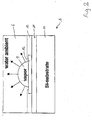
- FIG. 2 shows the structure of an ablation tool according to the invention 1.
- This has a silicon substrate 10 on which a thermally insulating Layer 11 and a resistance heating layer 12 applied is.
- the resistance heating layer 12 is over electrical contacts 13 (metallizations) contacted.
- the top surface of the resistance heating layer stands 12 diamond with the medium 6 in Contact. Now there is a current through the metallization 13 sent through the diamond layer 12, so heats the diamond layer 12 and forms again a gas bubble 5 in the medium 6.
- a 3 ⁇ m thick SiO 2 layer 11 is first deposited on a silicon carbide or silicon substrate 10 using CVD technology.
- the P + -doped diamond film acts as a resistance heating layer 12.
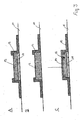
- Fig. 3 shows the structure of three in the sub-figures A-C various ablation tools according to the invention.
- a thermal insulation layer 11 made of SiO 2 is applied to a substrate 10 and on this a resistance heating layer 12 made of doped diamond.
- the metallic contacts 13 extend from the resistance heating layer 12 over the substrate 10.
- the resistance heating layer 12 is located directly on the substrate, and in FIG. 3C, an electrically insulating layer 14 made of intrinsic diamond or SiO 2 is applied to the resistance heating layer 12 and also to the parts of the metallic contacts 13 of the same level.
- This electrical insulation layer 14 has only a small layer thickness, so that heating of the medium is nevertheless reliably guaranteed.
- Electrical insulators come as materials with good thermal conductivity (e.g. diamond) in question.
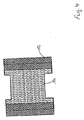
- 4 shows a top view of the resistance heating layer 12 and the electrical contact 13 for Ablation tools as shown in Figures 3A and 3B. It can be seen here that the resistance heating layer 12 constricted between the two contact layers and compared to the smallest width of the resistance heating layer 12 the contact areas between the metallization 13 and the resistance layer 12 are very wide and extensive. This will make the Contact resistance between the resistance layer 12 and the contacts 13 reduced, so that in essentially the heat generation in the resistance heating layer 12 takes place.
- the ablation instrument according to the invention is thus located in terms of frequency, energy per pulse and performance brought into the surrounding medium as well the power density further above the conventional one Ultrasound or laser processes.
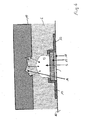
- Fig. 6 shows the use of an ablation tool according to. Fig. 3a.
- Medium 6 for example water, introduced. This now forms and destroys the bubbles according to the invention due to the cavitative effect of this bladder Surface of the item 15. This will Surface of the object 15 fragmented and worn. The fragments generated can then be used vacuumed or otherwise removed.
- Figure 7 shows an ablation tool that is similar Structure as in Fig. 3A.
- a capillary system above the resistance heating layer 12 17 arranged here in the vertical direction to the drawing level via a capillary 18 Medium transported to the surface of the heating element 12.
- the capillary system 17 there is still one Nozzle plate arranged through which the cross section of the Capillary is narrowed further and so a narrow nozzle opening is formed, the capillary 18 and the surface of the resistance heating layer 12 with the Connects outside of the ablation tool. at this arrangement, the gas bubble 5 generated by the nozzle opening 20 formed in the nozzle plate 19 thrown out, causing the cavitative effect on the item 15 can be reinforced. through of the capillary system it is still possible, always sufficient medium of the resistance heating layer to be evaporated 12 feed.
- FIG. 8 shows another ablation tool according to the invention, in which the resistance heating layer 12 is three-dimensionally shaped and in the substrate 10 forms a pot. Thereby the contact surface of the Resistance heating layer 12 enlarged with the medium 6 and the heating layer 12 itself forms a nozzle-like one Opening at their top.
- Fig. 9 shows the arrangement of an ablation tool 3A within an applicator rod 2.
- Die Resistance heating layer is with its surface on one of the side walls 24 of the tube trained applicator rod 2 arranged. This opposite on the circumference of the applicator tube 2 there is an opening in the wall 24 Surface of the resistance heating element 12 generated Steam bubble 5 can now exit through this opening and destroy item 15.
- fragments of material 21 are removed and in the Object 15 formed a cavity 16.
- the fragments 21 can then through the suction channel 8 trained interior of the tube 2 in Be sucked off in the direction of arrow A.
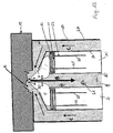
- FIG. 10 shows another example of an ablation tool in an applicator tube 2.
- the outer wall 24 of the applicator tube 2 forms at the same time the substrate.
- the applicator tube has, as in 10A, an opening can be seen in the axial direction 7.
- Figure 10B shows a cross-sectional view this opening 7.
- Resistance heating layer 12 arranged over a Rear side contact 22 and an electrical lead 23 and an electrical lead 23 'are contacted can.
- These lines 23, 23 'each run within of openings between the inner wall 25 and the outer wall 24 of the applicator tube.
- the Inner wall 25 is concentric and closes one Cavity 8 as a suction channel.
- the resistance heating layer 12 with a applied electrical current, so forms radially symmetrical gas bubble, which in the course of further heating grows together and out of the opening 7 is expelled.
- FIG. 11 shows a modification of an ablation tool, as shown in FIG. 10.
- the difference 10 now extends the outer wall 24 beyond the resistance heating layer 12 and angled then inwards towards the axis of the tube 2 from. In this way, the resistance heating layer 12 covered spaced apart, the outer wall 24 a concentric opening 7 for the exit of the Releases gas bubble.
- Fig. 11 it is shown how the invention Application tool also for removing a flexible Material 15 can be used. To do this this Material 15 sucked into the opening 7, where the generated gas bubbles 5 each small fragments 21st constrict. These will then go in the direction of the arrow B through the axially central suction channel 8 aspirated.
- Fig. 12 shows a section along the line A-AN Fig. 11. It can be seen that again the resistance heating layer 12 is arranged concentrically and such a radially symmetrical vapor bubble forms.
- FIG. 13 shows a further example according to the invention with an ablation instrument similar to that in Fig. 11 is reproduced.
- the tube 2 in a concentric but for this purpose spaced housing 27 housed.
- This housing 27 extends longitudinally the outer wall 24 of the tube 2 and narrows concentrically inward above the opening 7. This creates another nozzle opening 20 above the opening 7.
- a capillary system 17 which the supply of evaporation medium to the resistance heating element 12 serves.
- the medium flows in Direction of arrow C in the area between the Opening 7 and the nozzle opening 20.
- Heating the Resistance heating element 12 in turn becomes a concentric one Gas bubble 5 formed over the nozzle opening, directly on an object 15 is placed, acts on the object 15 and this fragmented there.
- a cavity 16 trained in the medium level 15 and the generated Fragments 21 of the removed material are over sucked off the suction opening 8 in the direction of arrow B.
Abstract
Description
Die vorliegende Erfindung betrifft ein Ablationsinstrument sowie ein Verfahren zum Schneiden, Fragmentieren und/oder Abtragen von Material. Derartige Verfahren werden benötigt, um von einem Gegenstand Material abzutragen bzw. diesen einzuschneiden oder zu zerstören. Insbesondere, jedoch nicht ausschließlich, werden derartige Verfahren und Ablationsinstrumente im Bereich der Medizin, insbesondere im Bereich der Katarakteextraktion, minimalinvasiven Chirurgie oder der Vitrektomie benötigt.The present invention relates to an ablation instrument and a method of cutting, fragmenting and / or removing material. Such procedures are needed to material from an object to remove or cut or to to destroy. In particular, but not exclusively, such procedures and ablation tools in the field of medicine, especially in the field of Cataract extraction, minimally invasive surgery or the vitrectomy needed.
Nach dem Stand der Technik werden zur Zerstörung der Augenlinse Ultraschallschneidelemente verwendet. Hierbei wird mittels eines Piezokristalls eine scharfe Schneide sehr rasch hin und her bewegt und dadurch das Material der Linse zerstückelt. Alternativ wird über einen Applikatorstab ein Target in die Linse eingeführt, auf das ein Laserstrahl gerichtet wird. Der Laserstrahl erhitzt nun das Target und dieses erzeugt eine Dampfblase in dem Material, die das Material aufgrund ihrer explosionsartigen Expansion im Umkreis der Blase zerstört. Dieses zerstörte fragmentierte Material kann dann beispielsweise durch das Applikatorröhrchen abgesaugt werden. Als Target werden dabei Titan oder Tantal verwendet, wobei durch Einstrahlung eines geeigneten Laserpulses kurzfristige Hotspots mit einer Temperatur von über 320°C erreicht werden.According to the prior art, the destruction of Eye lens uses ultrasonic cutting elements. Here, a sharp crystal is used by means of a piezo crystal Cutting very quickly moved back and forth and thereby the material of the lens dismembered. Alternatively, will a target into the lens via an applicator rod introduced to which a laser beam is directed. The laser beam now heats the target and generates it a vapor bubble in the material that the material due to their explosive expansion in Destroyed the perimeter of the bladder. This destroyed fragmented Material can then, for example, by the Aspirator tubes are aspirated. Become a target used titanium or tantalum, whereby by Short-term exposure to a suitable laser pulse Hotspots with a temperature of over 320 ° C reached become.
Diese herkömmlichen Systeme sind nicht zuletzt aufgrund des benötigten Lasersystems komplex und sehr teuer. Weiterhin sind die Applikatorstäbe komplex aufgebaut und kompliziert zu handhaben.These conventional systems are not least due to of the required laser system complex and very expensive. Furthermore, the applicator sticks are complex constructed and complicated to use.
Aufgabe der vorliegenden Erfindung ist es daher, ein Ablationsinstrument und ein Verfahren zum Schneiden, Fragmentieren und/oder Abtragen von Material eines Gegenstandes zur Verfügung zu stellen, das auf einfache, präzise und kostengünstige Weise eine derartige Materialbehandlung ermöglicht.The object of the present invention is therefore a Ablation instrument and a method of cutting, Fragmentation and / or removal of material To provide an object that is simple, such a precise and inexpensive way Allows material treatment.
Diese Aufgabe wird durch das Ablationsinstrument gemäß Anspruch 1 und das Verfahren nach Anspruch 38 gelöst. Vorteilhafte Weiterbildungen des erfindungsgemäßen Instrumentes und des erfindungsgemäßen Verfahrens werden in den jeweiligen abhängigen Ansprüchen gegeben.This task is accomplished by the ablation tool Claim 1 and the method according to claim 38 solved. Advantageous further developments of the invention Instrument and the inventive method are in the respective dependent claims given.
Erfindungsgemäß weist das Ablationsinstrument mindestens eine Widerstandsheizschicht aus dotiertem oder graphitischen Diamant auf. Diese Heizschicht wird nun über elektrische Zuleitungen und Ableitungen mit einem Strom beaufschlagt und dient zur Erzeugung sehr hoher Temperaturen. Die Heizschicht ist dabei auf einem Substrat angeordnet, so daß sie, beispielsweise über eine Halterung, in unmittelbaren Kontakt mit dem zu behandelnden Gegenstand oder in dessen Nähe gebracht werden kann. Sofern das Material nicht unmittelbar kontaktiert wird, kann zusätzlich zwischen die Heizschicht und das Material eine Flüssigkeit eingebracht werden. Die Heizschicht und damit die mit dieser kontaktierte Flüssigkeit oder das mit der Heizschicht kontaktierte Material werden nun durch kurze Strompulse temporär auf sehr hohe Temperaturen aufgeheizt, so daß sich Dampfblasen bilden, die wie auch im Stand der Technik zu einer explosionsartigen Absprengung oder Fragmentierung des Materials führen.According to the invention, the ablation instrument has at least a resistance heating layer made of doped or graphitic diamond. This heating layer is now about electrical leads and discharges with one Electricity is applied and is used for generation high temperatures. The heating layer is on one Substrate arranged so that, for example via a bracket, in direct contact with the brought to the object to be treated or in its vicinity can be. Unless the material is immediate can also be contacted between the Heating layer and the material introduced a liquid become. The heating layer and thus the one with it contacted liquid or that with the heating layer contacted material will now be shown by short Current pulses temporarily heated to very high temperatures, so that vapor bubbles form, which as well in the prior art to an explosive blasting or fragment the material.
Für das erfindungsgemäße Ablationsinstrument eignet sich eine Widerstandsheizschicht aus dotiertem oder graphitischem Diamant insbesondere aufgrund dessen hervorragenden hierfür geeigneten Eigenschaften. Diese sind insbesondere seine elektrische Leitfähigkeit, seine sehr hohe thermische Stabilität, die auch bei hohen Temperaturen nicht zu einer Zerstörung des Ablationsinstrumentes führt, sowie die hohe Wärmeleitfähigkeit von Diamant, die dazu führt, daß die Widerstandsheizschicht sehr kurzzeitig und überaus homogen aufgeheizt werden kann. Zu erwähnen ist ferner die geringe Wärmekapazität die eine schnelle Energieabgabe ermöglicht.Suitable for the ablation instrument according to the invention a resistance heating layer made of doped or graphitic diamond in particular because of this excellent properties. This are its electrical conductivity, its very high thermal stability, which also at high temperatures do not destroy the ablation instrument leads, as well as the high thermal conductivity of diamond, which leads to the resistance heating layer very short-term and extremely homogeneous can be heated. It should also be mentioned that low heat capacity which means a quick release of energy allows.
Vorteilhafterweise ist zwischen dem Substrat und der Widerstandsheizschicht eine thermisch isolierende Schicht angeordnet, um eine Ableitung der Wärme in das Substrat zu behindern und so die Aufheizbarkeit der Widerstandsheizschicht zu verbessern und die mögliche Frequenz der einzelnen Wärmepulse zu erhöhen. Is advantageously between the substrate and the Resistance heating layer a thermally insulating Layer arranged to dissipate heat in to hinder the substrate and thus the heatability to improve the resistance heating layer and the possible Increase the frequency of the individual heat pulses.
Weiterhin kann zwischen der thermisch isolierenden Schicht und der Widerstandsheizschicht eine oder mehrere Zwischenschichten, insbesondere aus intrinzischem Diamant, angeordnet sein, um beispielsweise die bei hohen Temperaturen durch ein thermisch isolierendes Substrat, beispielsweise aus SiO2, durchgehenden Leckströme, zu unterbinden und außerdem die Bekeimungsfähigkeit der thermisch isolierenden Schicht mit dotiertem oder graphitischem Diamant zu verbessern. Weiterhin kann die Widerstandsheizschicht auf ihrer dem zu behandelnden Material zugewandten anderen Seite eine elektrisch isolierende Schicht aufweisen, die dazu führt, daß der Strom tatsächlich ausschließlich auf die Widerstandsheizschicht beschränkt wird.Furthermore, one or more intermediate layers, in particular made of intrinsic diamond, can be arranged between the thermally insulating layer and the resistance heating layer in order, for example, to prevent the leakage currents which pass through at high temperatures through a thermally insulating substrate, for example made of SiO 2 , and also to prevent germs from seeding To improve thermal insulating layer with doped or graphitic diamond. Furthermore, the resistance heating layer on its other side facing the material to be treated can have an electrically insulating layer, which leads to the fact that the current is actually restricted exclusively to the resistance heating layer.
Ganz wesentlich bei der vorliegenden Erfindung ist weiterhin, daß Diamant als Oberfläche chemisch und physikalisch inert ist und daher sich insbesondere für medizinische, beispielsweise intrakorporale, Anwendungen eignet.It is very important in the present invention furthermore that diamond as chemical and surface is physically inert and therefore in particular for medical, for example intracorporeal, applications suitable.
Erfindungsgemäß kann die Widerstandsheizschicht mit einzelnen Strompulsen mit Frequenzen bis ca. 50 kHz bei Kontaktierung mit Wasser beaufschlagt werden. Diese Strompulse können periodisch oder aperiodisch wiederholt werden. Die Grenzfrequenz für die Strompulse ist dabei selbstverständlich abhängig vom Umgebungsmedium, insbesondere dessen Viskosität und thermische Eigenschaften.According to the resistance heating layer with individual current pulses with frequencies up to approx. 50 kHz be contacted with water when contacting. These current pulses can be periodic or aperiodic be repeated. The cut-off frequency for the current pulses is of course dependent on the surrounding medium, especially its viscosity and thermal Characteristics.
Vorteilhaft an der vorliegenden Erfindung ist, daß keine komplizierten optischen Bauelemente (Laser) oder mechanisch bewegte Teile (Klinge mit Piezoantrieb) verwendet werden. Damit ist auch die Wahrscheinlichkeit für ein Versagen des Ablationsinstrumentes weitgehend ausgeschlossen. Bei dem erfindungsgemäßen Ablationsinstrument sind Leistungsdichten von über 700 kW pro cm2 bzw. sehr kleine Flächen der Widerstandsheizschicht von beispielsweise 0,5 mm2 möglich, da Diamant eine extrem hohe mechanische Stabilität, elektrische Leitfähigkeit, thermische Leitfähigkeit und einen geringen thermischen Expansionskoeffizienten aufweist. Aufgrund der guten thermischen Leitfähigkeit und der homogenen Verteilung können auch Heizelemente > 1 mm2, bevorzugt 1 bis 10 mm2, ganz besonders bevorzugt 1 bis 5 mm2 realisiert werden, mit denen große Blasen erzeugt werden können. Dies ermöglicht eine unmittelbare Umwandlung elektrischer in Heizenergie, eine sehr homogene Wärmeverteilung auf dem Heizelement, keine Kavitationsschäden am Heizelement aufgrund der erzeugte Blase sowie keinen thermischen Streß für das Heizelement durch die extrem rasche Aufheizung und Abkühlung. Insgesamt ist damit ein sehr zuverlässiges Ablationsinstrument gegeben, das aufgrund seiner Dimensionierung und Kosten selbst als Einweginstrument verwendet werden kann.An advantage of the present invention is that no complicated optical components (laser) or mechanically moving parts (blade with piezo drive) are used. This means that the probability of the ablation instrument failing is largely excluded. In the ablation instrument according to the invention, power densities of over 700 kW per cm 2 or very small areas of the resistance heating layer of, for example, 0.5 mm 2 are possible, since diamond has extremely high mechanical stability, electrical conductivity, thermal conductivity and a low thermal expansion coefficient. Due to the good thermal conductivity and the homogeneous distribution, heating elements> 1 mm 2 , preferably 1 to 10 mm 2 , very particularly preferably 1 to 5 mm 2, can be realized, with which large bubbles can be generated. This enables direct conversion of electrical energy into heating energy, a very homogeneous heat distribution on the heating element, no cavitation damage to the heating element due to the bladder generated and no thermal stress for the heating element due to the extremely rapid heating and cooling. Overall, this provides a very reliable ablation tool that can be used as a single-use tool due to its dimensions and costs.
Wird in das Ablationsinstrument, beispielsweise unmittelbar in die Heizschicht, ein Thermoelement mit integriert, so ist auch eine Steuerung der erzeugten Temperatur, beispielsweise in Abhängigkeit vom Umgebungsmedium, möglich. Das Heizelement selbst kann dabei das Thermoelement darstellen.Will be in the ablation tool, for example immediately into the heating layer using a thermocouple integrated, so is a control of the generated Temperature, for example depending on the surrounding medium, possible. The heating element itself can represent the thermocouple.
Erfindungsgemäß kann durch eine vorgewählte Gestaltung der Widerstandsheizschicht die Form der erzeugten Blase vorgewählt werden. Auch die Temperatur, bei der die Blase erzeugt wird, kann bestimmt werden, beispielsweise als nahe oder oberhalb der Spinodaltemperatur. According to the invention by a preselected design the shape of the resistance heating layer Bubble can be selected. Even the temperature at the bubble is generated can be determined for example as near or above the spinodal temperature.
Bei einem Ablationsinstrument, das mindestens eine Widerstandsschicht aus dotiertem oder graphitischem Diamant (diamond-like carbon) enthält, die auf einer thermisch isolierenden Schicht angeordnet ist, ist die Diffusion der in der Widerstandsschicht generierten Wärme deutlich reduziert und der Wirkungsgrad der Heizschicht somit erheblich verbessert. Im Gegensatz zu Heizschichten des Standes der Technik befindet sich die erfindungsgemäße Heizschicht aufgrund entsprechender Strukturierung weder in thermischem Kontakt zu einem großflächigen Diamantfilm noch zu anderen Wärmesenken. Eine laterale Diffusion der Wärme läßt sich durch Maßnahmen wie Mesaätzen oder selektives Wachstum verhindern. Aufgrund der eine thermische Isolationsschicht aufweisenden vertikalen Schichtstruktur wird auch eine Wärmediffusion in das Substrat ausgeschlossen. Die Verwendung der Isolationsschicht macht das aus dem Stand der Technik bekannte Dünnen des Substrates überflüssig, so daß die erfindungsgemäßen Heizschicht auf mechanisch stabilen, kommerziellen Substraten angeordnet werden können. Die isolierende Schicht weist bevorzugt eine Wärmeleitfähigkeit von unter 1 W cm-1 K-1 bei 300 K auf und kann aus Materialien wie beispielsweise Siliziumoxiden, Siliziumnitriden, Siliziumoxinitriden und Aluminiumoxiden bestehen. Um eine ausreichende thermische Isolierung der Heizschicht zu gewährleisten, sollte die Dicke der isolierenden Schicht mindestens 0,25 µm betragen und bevorzugt in einem Bereich zwischen 1 µm und 10 µm liegen. Besonders bevorzugt besteht die Isolationsschicht aus amorphen Materialien, welche geringe thermische Leitfähigkeiten besitzen. Die Isolationsschicht weist bevorzugt keine oder eine nur geringe elektrische Leitfähigkeit auf. In the case of an ablation instrument which contains at least one resistance layer made of doped or graphitic diamond (diamond-like carbon), which is arranged on a thermally insulating layer, the diffusion of the heat generated in the resistance layer is significantly reduced and the efficiency of the heating layer is thus considerably improved. In contrast to heating layers of the prior art, the heating layer according to the invention is neither in thermal contact with a large-area diamond film nor with other heat sinks due to the corresponding structuring. Lateral diffusion of the heat can be prevented by measures such as mesa etching or selective growth. Due to the vertical layer structure having a thermal insulation layer, heat diffusion into the substrate is also excluded. The use of the insulation layer makes the thinning of the substrate known from the prior art superfluous, so that the heating layer according to the invention can be arranged on mechanically stable, commercial substrates. The insulating layer preferably has a thermal conductivity of less than 1 W cm -1 K -1 at 300 K and can consist of materials such as silicon oxides, silicon nitrides, silicon oxynitrides and aluminum oxides. In order to ensure adequate thermal insulation of the heating layer, the thickness of the insulating layer should be at least 0.25 μm and preferably in a range between 1 μm and 10 μm. The insulation layer particularly preferably consists of amorphous materials which have low thermal conductivities. The insulation layer preferably has no or only a low electrical conductivity.
Die dotierte Widerstandsheizschicht kann direkt auf der isolierenden Schicht gewachsen werden. Alternativ ist es auch denkbar, zwischen Widerstandsheizschicht und isolierender Schicht eine oder mehrere Zwischenschichten vorzusehen. Um eine laterale Wärmediffusion zu vermeiden, sollte die mindestens eine Zwischenschicht entweder selbst ein thermischer Isolator sein oder aber lateral strukturiert werden.The doped resistance heating layer can be applied directly of the insulating layer. alternative it is also conceivable between the resistance heating layer and insulating layer one or more intermediate layers provided. Lateral heat diffusion to avoid the at least one intermediate layer either be a thermal insulator yourself or laterally structured.
Die Widerstandsheizschicht des Ablationsinstrumentes besitzt bevorzugt eine Fläche von weniger als 1 mm2 und besonders bevorzugt von weniger 100 x 100 µm2.The resistance heating layer of the ablation instrument preferably has an area of less than 1 mm 2 and particularly preferably less than 100 x 100 µm 2 .
Wie bereits ausgeführt, können auch Flächen von 1 bis 10 mm2, bevorzugt 1 bis 5 mm2 realisiert werden, mit denen eine Blase erzeugt werden kann.As already stated, areas of 1 to 10 mm 2 , preferably 1 to 5 mm 2, can also be realized with which a bubble can be generated.
Eine bevorzugte Ausgestaltung der Erfindung sieht vor, die Wärmeabgabe des erfindungsgemäßen Ablationsinstrumentes durch mit der Heizschicht monolithisch integrierte Temperatursensoren zu erfassen, um eine exakte Steuerung des Ablationsinstrumentes zu gewährleisten. Die Dotierstoffkonzentration in der Widerstandsschicht sollte zur Erzeugung eines temperaturunabhängigen elektrischen Widerstandes daher mindestens etwa 1019. cm-3 betragen. Bei geringerer Dotierstoffkonzentration und wenn eine gewisse Temperaturabhängigkeit des Heizverhaltens in Kauf genommen wird, kann das Ablationsinstrument auch selbst als Temperatursensor fungieren.A preferred embodiment of the invention provides for the heat emission of the ablation instrument according to the invention to be recorded by temperature sensors integrated monolithically with the heating layer in order to ensure precise control of the ablation instrument. The dopant concentration in the resistance layer should therefore be at least about 10 19 in order to produce a temperature-independent electrical resistance. cm -3 . With a lower dopant concentration and if a certain temperature dependence of the heating behavior is accepted, the ablation instrument itself can also function as a temperature sensor.
Im folgenden werden einige Beispiele erfindungsgemä- ßer Ablationsinstrumente und erfindungsgemäßer Verfahren gegeben. In the following, some examples according to the invention are Ablation instruments and methods according to the invention given.
- Fig. 1Fig. 1
- ein herkömmliches Ablationsinstrument;a conventional ablation instrument;
- Fig. 2Fig. 2
- den Aufbau eines erfindungsgemäßen Ablationsinstrumentes;the construction of an ablation instrument according to the invention;
- Fig. 3Fig. 3
- verschiedene weitere Ablationsinstrumente;various other ablation instruments;
- Fig. 4Fig. 4
- eine Aufsicht auf ein Ablationsinstrument;supervision of an ablation tool;
- Fig. 5Fig. 5
- den Verlauf der Blasenerzeugung mit einem erfindungsgemäßen Ablationsinstrument;the course of the bubble generation with a ablation instrument according to the invention;
- Fig. 6 bis Fig. 136 to Fig. 13
- verschiedene Formen erfindungsgemäßer Ablationsinstrumente.different forms of ablation instruments according to the invention.
Fig. 1 zeigt ein Ablationsinstrument 1 nach dem Stand
der Technik. Dieses Ablationsinstrument besteht aus
einem Applikatorstab in Form eines Röhrchens 2, das
an dem in Fig. 1 dargestellten Ende eine seitliche
Öffnung 7 aufweist. Weiterhin ist unter einem Winkel
zu der axialen Richtung des Röhrchens 2 ein Target 3
angeordnet, das beispielsweise aus Titan oder Tantal
besteht. Dieses Röhrchen 2 besitzt eine kanalartige
Durchgangsöffnung 8, die durch die Außenwände 24 des
Röhrchens 2 gebildet wird und mit der Öffnung 7 kommuniziert.1 shows an ablation instrument 1 according to the prior art
of the technique. This ablation tool consists of
an applicator rod in the form of a
Wie in Fig. 1 dargestellt, wird nun zur Materialzerstörung
ein Laserstrahl 4 auf das Target 3 gegeben.
Das Target 3 steht mit einer Flüssigkeit oder dem umgebenden
Gewebe, beispielsweise einer Linse, in Kontakt.
Durch den Laserstrahl 4 wird das Target 3 auf
eine sehr hohe Temperatur aufgeheizt, gewöhnlich bis
zu 321°C. Hierdurch wird das mit dem Target 3 in Kontakt
befindliche Medium 6 überhitzt und bildet eine
Gasblase 5, die sich explosionsartig in Richtung der
dargestellten fünf Pfeile ausdehnen. Diese Gasblase
überträgt eine Schockwelle auf das Medium 6 und zerstört
dieses dadurch. Anschließend wird das abgetragene
Material in Richtung des Pfeiles A durch die
Öffnung 8 abgesaugt.As shown in Fig. 1, now becomes material destruction
a
Fig. 2 zeigt die Struktur eines erfindungsgemäßen Ablationswerkzeuges
1. Dieses weist ein Siliziumsubstrat
10 auf, auf dem eine thermisch isolierende
Schicht 11 sowie eine Widerstandsheizschicht 12 aufgebracht
ist. Die Widerstandsheizschicht 12 ist über
elektrische Kontakte 13 (Metallisierungen) kontakiert.
Wiederum steht die obere Fläche der Widerstandheizschicht
12 aus Diamant mit dem Medium 6 in
Kontakt. Wird nun ein Strom über die Metallisierung
13 durch die Diamantschicht 12 geschickt, so heizt
sich die Diamantschicht 12 auf und bildet wiederum
eine Gasblase 5 in dem Medium 6 aus.2 shows the structure of an ablation tool according to the invention
1. This has a
Vorteilhaft bei dem erfindungsgemäßen Ablationsinstrument ist weiterhin aufgrund der Inertheit des aktiven Elementes die gute Reinigungsmöglichkeit, da kaum oder gar kein Gewebe anhaftet.Advantageous in the ablation instrument according to the invention is still active due to the inertia Elementes the good cleaning possibility because little or no tissue adheres.
Zur Herstellung der in Fig. 2 dargestellten Schichtstruktur
wird auf einem Siliziumcarbid oder Siliziumsubstrat
10 zunächst mit Hilfe der CVD-Technik eine 3
µm dicke SiO2-Schicht 11 abgeschieden. Ebenfalls mittels
eines CVD-Verfahrens wird auf der SiO2-Schicht
11 eine P+-dotierte Diamantschicht mit einer Dotierstoffkonzentration
von 1020 bis 1021 cm-3 und einer
Dicke von 400 nm bis 10 µm, bevorzugt 1 bis 3 µm aufgewachsen.
Der P+-dotierte Diamantfilm fungiert als
Widerstandheizschicht 12.To produce the layer structure shown in FIG. 2, a 3 μm thick SiO 2 layer 11 is first deposited on a silicon carbide or
Fig. 3 zeigt in den Teilfiguren A-C den Aufbau dreier verschiedener erfindungsgemäßer Ablationswerkzeuge. Fig. 3 shows the structure of three in the sub-figures A-C various ablation tools according to the invention.
In Fig. 3A wird auf einem Substrat 10 eine thermische
Isolationsschicht 11 aus SiO2 aufgebracht und auf
dieser eine Widerstandsheizschicht 12 aus dotiertem
Diamant. Die metallischen Kontaktierungen 13 erstrekken
sich von der Widerstandsheizschicht 12 über das
Substrat 10.In FIG. 3A, a
In Fig. 3B befindet sich die Widerstandsheizschicht
12 unmittelbar auf dem Substrat und in Fig. 3C ist
auf Widerstandsheizschicht 12 und auch die niveaugleichen
Teile der metallischen Kontaktieren 13 eine
elektrisch isolierende Schicht 14 aus intrinsischem
Diamant oder SiO2 aufgebracht. Diese elektrische Isolationsschicht
14 besitzt nur eine geringe Schichtdicke,
damit eine Erhitzung des Mediums dennoch zuverlässig
gewährleistet ist.In FIG. 3B, the
Als Materialien kommen hierbei elektrische Isolatoren
mit guter Wärmeleitfähigkeit (z.B. Diamant) in Frage.
Fig. 4 zeigt eine Aufsicht auf die Widerstandsheizschicht
12 und die elektrische Kontaktierung 13 für
Ablationswerkzeuge wie in Fig. 3A und 3B dargestellt.
Hier ist zu erkennen, daß die Widerstandsheizschicht
12 zwischen den beiden Kontaktschichten eingeschnürt
ist und verglichen mit der geringsten Breite der Widerstandsheizschicht
12 die Kontaktflächen zwischen
der Metallisierung 13 und der Widerstandsschicht 12
sehr breit und großflächig sind. Dadurch werden die
Übergangswiderstände zwischen der Widerstandsschicht
12 und den Kontaktierungen 13 herabgesetzt, so daß im
wesentlichen die Wärmeerzeugung in der Widerstandsheizschicht
12 erfolgt.Electrical insulators come as materials
with good thermal conductivity (e.g. diamond) in question.
4 shows a top view of the
Fig. 5 zeigt die Erzeugung einer Gas- bzw. Dampfblase
in Wasser bei einer elektrischen Leistung von 10 W in
der zeitlichen Abfolge, wobei die einzelnen Bilder
von links nach rechts und oben nach unten aufeinanderfolgen.
Die zeitlichen Abstände zwischen den einzelnen
Bildern betragen 1 µsec, wobei das erste Bild
links oben zu einem Zeitpunkt t = 5 µsec nach dem Beginn
des Stromflusses durch den Heizer beginnt und
das letzte Bild recht unten den Zeitpunkt bei t = 16
µsec angibt. Bei diesem Beispiel wurden insgesamt für
8 µsec ein elektrischer Strom auf das Widerstandsheizelement
12 gegeben.5 shows the generation of a gas or vapor bubble
in water with an electrical power of 10 W in
the chronological order, the individual images
Follow each other from left to right and from top to bottom.
The time intervals between each
Images are 1 µsec, with the first image
top left at a time t = 5 µsec after the start
the current flow through the heater begins and
the last picture at the bottom right shows the time at t = 16
µsec indicates. In this example, a total of
8 µsec an electrical current on the resistance
Wie in Fig 5 zu erkennen ist, bilden sich bereits
nach 7 µsec kleine lokale Gasblasen, die sich bis
nach 12 µsec zu einer großen Gasblase vereinigen, die
ihren größten Ausdehnungszustand nach 13 µsec ausbildet.
Danach bildet sich die Gasblase 5 wieder zurück.As can be seen in FIG. 5, are already being formed
after 7 µsec small local gas bubbles that are up to
combine into a large gas bubble after 12 µsec
develops its largest state of expansion after 13 µsec.
The
Diese rasche innerhalb von µ-Sekunden erfolgende Ausbildung und Rückbildung der Gasblasen ermöglicht eine Frequenz der Gasblasenbildung zwischen 0 und 30.000 Hertz bei einer Energie pro Puls von 0-7 mJ. Dies entspricht Leistungen von 0-145 W. Es wurden daher bereits Leistungsdichten von 0-210 kW/cm2 bei einer Oberfläche des Heizelementes von 60 x 60 µm2, einer Strompulsdauer von 7 µsec und einer Frequenz von 20 kHz gemessen.This rapid formation and regression of the gas bubbles within µ-seconds enables a frequency of gas bubble formation between 0 and 30,000 Hertz with an energy per pulse of 0-7 mJ. This corresponds to powers of 0-145 W. Power densities of 0-210 kW / cm 2 have therefore already been measured with a surface of the heating element of 60 x 60 µm 2 , a current pulse duration of 7 µsec and a frequency of 20 kHz.
Damit liegt das erfindungsgemäße Ablationsinstrument bezüglich der Frequenz, der Energie pro Puls und der in das umgebende Medium eingebrachten Leistung sowie der Leistungsdichte weiter oberhalb der herkömmlichen Ultraschall- oder Laserverfahren.The ablation instrument according to the invention is thus located in terms of frequency, energy per pulse and performance brought into the surrounding medium as well the power density further above the conventional one Ultrasound or laser processes.
Fig. 6 zeigt den Einsatz eines Ablationswerkzeuges
gemäß. Fig. 3a. Im Einsatz zum Materialabtrag von einem
Gegenstand 15. In diesem Falle wird zwischen dem
Gegenstand 15 und die Widerstandsheizschicht 12 ein
Medium 6, beispielsweise Wasser, eingebracht. Dieses
bildet nun die erfindungsgemäßen Blasen aus und zerstört
durch die kavitative Wirkung dieser Blase die
Oberfläche des Gegenstandes 15. Dadurch wird die
Oberfläche des Gegenstandes 15 fragmentiert und abgetragen.
Die erzeugten Bruchstücke können dann anschließend
abgesaugt oder anderweitig entfernt werden.Fig. 6 shows the use of an ablation tool
according to. Fig. 3a. In use to remove material from one
Fig. 7 zeigt ein Ablationswerkzeug, das einen ähnlichen
Aufbau wie in Fig. 3A aufweist. Zusätzlich ist
oberhalb der Widerstandsheizschicht 12 ein Kapillarsystem
17 angeordnet, das hier in senkrechter Richtung
zur Zeichnungsebene über eine Kapillare 18 ein
Medium auf die Oberfläche des Heizelementes 12 transportiert.Figure 7 shows an ablation tool that is similar
Structure as in Fig. 3A. In addition is
a capillary system above the
Oberhalb des Kapillarsystems 17 ist weiterhin eine
Düsenplatte angeordnet, durch die der Querschnitt der
Kapillare weiter verengt wird und so eine schmale Düsenöffnung
gebildet wird, die die Kapillare 18 und
die Oberfläche der Widerstandsheizschicht 12 mit der
Außenseite des Ablationswerkzeuges verbindet. Bei
dieser Anordnung wird die erzeugte Gasblase 5 durch
die in der Düsenplatte 19 gebildete Düsenöffnung 20
ausgeschleudert, wodurch die kavitative Wirkung auf
den Gegenstand 15 noch verstärkt werden kann. Mittels
des Kapillarsystems ist es weiterhin möglich, immer
ausreichendes zu verdampfendes Medium der Widerstandsheizschicht
12 zuzuführen.Above the
Fig. 8 zeigt ein weiteres erfindungsgemäßes Ablationswerkzeug,
bei dem die Widerstandsheizschicht 12
dreidimensional geformt ist und in dem Substrat 10
einen Topf bildet. Dadurch die Kontaktoberfläche der
Widerstandsheizschicht 12 mit dem Medium 6 vergrößert
und die Widerheizschicht 12 bildet selbst eine düsenartige
Öffnung an ihrer Oberseite aus.8 shows another ablation tool according to the invention,
in which the
Fig. 9 zeigt die Anordnung eines Ablationswerkzeuges
gemäß Fig. 3A innerhalb eines Applikatorstabes 2. Die
Widerstandsheizschicht ist dabei mit ihrer Oberfläche
auf einer der Seitenwandungen 24 des als Röhrchen
ausgebildeten Applikatorstabes 2 angeordnet. Dieser
gegenüber auf dem Umfang des Applikatorröhrchens 2
ist in der Wandung 24 eine Öffnung 7. Die auf der
Oberfläche des Widerstandsheizelementes 12 erzeugte
Dampfblase 5 kann nun durch diese Öffnung austreten
und den Gegenstand 15 zerstören. In diesem Bereich
werden Materialbruchstücke 21 abgetragen und in dem
Gegenstand 15 eine Kavität 16 ausgebildet. Die Bruchstücke
21 können anschließend durch den als Absaugkanal
8 ausgebildeten Innenraum des Röhrchens 2 in
Richtung des Pfeiles A abgesaugt werden.Fig. 9 shows the arrangement of an ablation tool
3A within an
Hier ist zu erwähnen, daß durch die lineare Bewegung
des Applikatorröhrchens 2 ein Schnitt in das Material
15 eingebracht werden kann, so daß die erfindungsgemäße
Vorrichtung sich auch zum Schneiden von Gegenständen
eignet. Diese Vorrichtung kann auch in der
Endoskopie eingesetzt werden.It should be mentioned here that due to the linear movement
of the applicator tube 2 a cut in the
Fig. 10 zeigt ein weiteres Beispiel eines Ablationswerkzeuges
in einem Applikatorröhrchen 2. Die Außenwandung
24 des Applikatorröhrchens 2 bildet zugleich
das Substrat. Das Applikatorröhrchen besitzt, wie in
Fig. 10A zu sehen ist, in axialer Richtung eine Öffnung
7. Fig. 10B zeigt eine Querschnittsansicht auf
diese Öffnung 7. Wie zu erkennen ist, ist der Abstand
von der Öffnung ringförmig die Öffnung umgeben eine
Widerstandsheizschicht 12 angeordnet, die über einen
Rückseitkontakt 22 und eine elektrische Zuleitung 23
und eine elektrische Ableitung 23' kontaktiert werden
kann. Diese Leitungen 23, 23' verlaufen jeweils innerhalb
von Öffnungen zwischen der Innenwandung 25
und der Außenwandung 24 des Applikatorröhrchens. Die
Innenwandung 25 ist konzentrisch und schließt einen
Hohlraum 8 als Absaugkanal ein.10 shows another example of an ablation tool
in an
Wird nun die Widerstandsheizschicht 12 mit einem
elektrischen Strom beaufschlagt, so bildet sich eine
radialsymmetrische Gasblase aus, die im Laufe des
weiteren Heizens zusammenwächst und aus der Öffnung 7
ausgestoßen wird.Now the
Fig. 11 zeigt eine Modifikation eines Ablationswerkzeuges,
wie es in Fig. 10 dargestellt ist. Im Unterschied
zu Fig. 10 erstreckt sich nun die Außenwandung
24 über die Widerstandsheizschicht 12 hinaus und winkelt
dann nach innen in Richtung der Achse des Röhrchens
2 ab. Auf diese Weise wird die Widerstandsheizschicht
12 beabstandet überdeckt, wobei die Außenwandung
24 eine konzentrische Öffnung 7 zum Austritt der
Gasblase freiläßt.11 shows a modification of an ablation tool,
as shown in FIG. 10. The
In Fig. 11 ist dargestellt, wie das erfindungsgemäße
Applikationswerkzeug auch zum Abtrag eines flexiblen
Materials 15 verwendet werden kann. Hierzu wird dieses
Material 15 in die Öffnung 7 eingesaugt, wo die
erzeugten Gasblasen 5 jeweils kleine Bruchstücke 21
abschnüren. Diese werden dann in Richtung des Pfeiles
B durch den axial mittig verlaufenden Absaugkanal 8
abgesaugt.In Fig. 11 it is shown how the invention
Application tool also for removing a
Fig. 12 zeigt einen Schnitt längs der Linie A-AN Fig.
11. Zu erkennen ist, daß wiederum die Widerstandsheizschicht
12 konzentrisch angeordnet ist und
so eine radialsymmetrische Dampfblase ausbildet. Fig. 12 shows a section along the line A-AN Fig.
11. It can be seen that again the
Fig. 13 zeigt ein weiteres erfindungsgemäßes Beispiel
mit einem Ablationsinstrument, das demjenigen in Fig.
11 nachgebildet ist. Zusätzlich zu der Anordnung in
Fig. 11 ist nunmehr das Röhrchen 2 in ein konzentrisch
hierzu aber beabstandet angeordnetes Gehäuse
27 eingehäust. Diese Gehäuse 27 erstreckt sich längs
der Außenwandung 24 des Röhrchens 2 und verengt sich
in konzentrischer Weise nach innen oberhalb der Öffnung
7. Es bildet dadurch eine weitere Düsenöffnung
20 oberhalb der Öffnung 7 aus.13 shows a further example according to the invention
with an ablation instrument similar to that in Fig.
11 is reproduced. In addition to the arrangement in
Fig. 11 is now the
In dem Abstand zwischen der Außenwandung 24 und dem
Gehäuse 27 ist ein Kapillarsystem 17 angeordnet, das
der Zufuhr von Verdampfungsmedium zu dem Widerstandsheizelement
12 dient. Das Medium fließt in
Richtung des Pfeiles C in den Bereich zwischen der
Öffnung 7 und der Düsenöffnung 20. Beim Beheizen des
Widerstandsheizelementes 12 wird wiederum eine konzentrische
Gasblase 5 ausgebildet, die über die Düsenöffnung,
die unmittelbar auf einem Gegenstand 15
aufgesetzt ist, auf den Gegenstand 15 einwirkt und
diesen dort fragmentiert. Dabei wird eine Kavität 16
in dem Mediumstand 15 ausgebildet und die erzeugten
Bruchstücke 21 des abgetragenen Materials werden über
die Absaugöffnung 8 in Richtung des Pfeiles B abgesaugt.In the distance between the
Dadurch, daß bei diesem Beispiel das zu verdampfende
Medium über den Kanal 17 zu der Oberfläche des Gegenstandes
15 zugeführt wird, ist es damit auch möglich,
Festkörper zu fragmentieren, zu schneiden oder abzutragen.Because in this example, what is to be evaporated
Medium via
Claims (42)
mit einem Trägersubstrat,
mindestens einer auf dem Substrat angeordneten Widerstandsheizschicht aus dotiertem oder graphitischem Diamant (DLC) sowie
mindestens einer elektrischen Zuleitung und mindestens einer elektrischen Ableitung, die beide an verschiedenen Stellen mit der Widerstandsheizschicht elektrisch kontaktiert sind.Ablation instrument for cutting, fragmenting and / or removing material from an object
with a carrier substrate,
at least one resistance heating layer of doped or graphitic diamond (DLC) arranged on the substrate and
at least one electrical lead and at least one electrical lead, both of which are electrically contacted at different points with the resistance heating layer.
dadurch gekennzeichnet, daß das Substrat Silizium, Siliziumkarbid, Siliziumoxide wie SiO2, Glas, refraktive Metalle oder Karbide hiervon, Saphir, Magnesiumoxid, Diamant, Graphit und/oder Germanium enthält oder daraus besteht.Ablation instrument according to the preceding claim,
characterized in that the substrate contains or consists of silicon, silicon carbide, silicon oxides such as SiO 2 , glass, refractive metals or carbides thereof, sapphire, magnesium oxide, diamond, graphite and / or germanium.
dadurch gekennzeichnet, daß das Substrat zumindest bereichsweise eine Membran ist.Ablation instrument according to claim 1,
characterized in that the substrate is a membrane at least in some areas.
dadurch gekennzeichnet, daß die Widerstandsheizschicht eine Fläche von weniger als 10 mm2, bevorzugt weniger als 5 mm2 aufweist.Ablation instrument according to one of the preceding claims,
characterized in that the resistance heating layer has an area of less than 10 mm 2 , preferably less than 5 mm 2 .
dadurch gekennzeichnet, daß die Widerstandsschicht eine Dotierstoffkonzentration größer oder gleich 5x1017 cm-3 aufweist.Ablation instrument according to one of the preceding claims,
characterized in that the resistance layer has a dopant concentration greater than or equal to 5x10 17 cm -3 .
dadurch gekennzeichnet, daß die Widerstandsschicht mit Bor, Phosphor, Stickstoff, Lithium und/oder Schwefel dotiert ist.Ablation instrument according to one of the preceding claims,
characterized in that the resistance layer is doped with boron, phosphorus, nitrogen, lithium and / or sulfur.
dadurch gekennzeichnet, daß die Widerstandsschicht eine thermische Leistungsdichte zwischen 0 und 1,5 GW/cm3 aufweist.Ablation instrument according to one of the preceding claims,
characterized in that the resistance layer has a thermal power density between 0 and 1.5 GW / cm 3 .
dadurch gekennzeichnet, daß die Widerstandsschicht einen spezifischen Widerstand zwischen 1 µΩcm und 100 mΩcm aufweist.Ablation instrument according to one of the preceding claims,
characterized in that the resistance layer has a specific resistance between 1 µΩcm and 100 mΩcm.
dadurch gekennzeichnet, daß zwischen dem Substrat und der Widerstandsheizschicht eine thermisch isolierende Schicht angeordnet ist.Ablation instrument according to the preceding claim,
characterized in that a thermally insulating layer is arranged between the substrate and the resistance heating layer.
dadurch gekennzeichnet, daß die thermisch isolierende Schicht eine Wärmeleitfähigkeit von - unter 1 W·cm-1·K-1 bei 300 K aufweist.Ablation instrument according to the preceding claim,
characterized in that the thermally insulating layer has a thermal conductivity of - below 1 W · cm -1 · K -1 at 300 K.
dadurch gekennzeichnet, daß die thermisch isolierende Schicht aus einem amorphen Material - besteht. Ablation instrument according to one of the two preceding claims,
characterized in that the thermally insulating layer consists of an amorphous material.
dadurch gekennzeichnet, daß die thermisch isolierende Schicht aus einem elektrischen Nichtleiter besteht.Ablation instrument according to one of the three preceding claims,
characterized in that the thermally insulating layer consists of an electrical non-conductor.
dadurch gekennzeichnet, daß das Material der thermisch isolierenden Schicht ausgewählt ist aus Siliziumoxiden, Siliziumnitriden, Siliziumoxinitriden und Aluminiumoxiden.Ablation instrument according to one of the four preceding claims,
characterized in that the material of the thermally insulating layer is selected from silicon oxides, silicon nitrides, silicon oxynitrides and aluminum oxides.
dadurch gekennzeichnet, daß zwischen dem Substrat oder der thermisch isolierenden Schicht und der Widerstandsheizschicht mindestens eine Zwischenschicht angeordnet ist.Ablation instrument according to one of the preceding claims,
characterized in that at least one intermediate layer is arranged between the substrate or the thermally insulating layer and the resistance heating layer.
dadurch gekennzeichnet, daß die Zwischenschicht aus intrinsischem Diamant besteht.Ablation instrument according to the preceding claim,
characterized in that the intermediate layer consists of intrinsic diamond.
dadurch gekennzeichnet, daß die Zwischenschicht lateral strukturiert ist.Ablation instrument according to one of the two preceding claims,
characterized in that the intermediate layer is laterally structured.
dadurch gekennzeichnet, daß auf der Widerstandsschicht eine elektrisch isolierende Schicht angeordnet ist. Ablation instrument according to one of the preceding claims,
characterized in that an electrically insulating layer is arranged on the resistance layer.
dadurch gekennzeichnet, daß die
mit dem zu behandelnden Gegenstand kontaktierbare Oberfläche H-terminiert ist.Ablation instrument according to one of the preceding claims,
characterized in that the
is H-terminated with the surface to be treated.
dadurch gekennzeichnet, daß das Trägersubstrat an einem Ende eines Stabes angeordnet ist.Ablation instrument according to one of the preceding claims,
characterized in that the carrier substrate is arranged at one end of a rod.
dadurch gekennzeichnet, daß der Applikatorstab als Applikatorröhrchen ausgebildet ist, das im Bereich eines ersten Endes eine erste Öffnung aufweist und das Substrat in dem Hohlraum der ersten Öffnung benachbart derart angeordnet ist, daß die Oberfläche der Widerstandsheizschicht der ersten Öffnung zugewandt ist.Ablation instrument according to the preceding claim,
characterized in that the applicator rod is designed as an applicator tube which has a first opening in the region of a first end and the substrate is arranged in the cavity adjacent to the first opening such that the surface of the resistance heating layer faces the first opening.
dadurch gekennzeichnet, daß die erste Öffnung in axialer Richtung des Applikatorröhrchens oder seitlich auf dem Umfang des Applikatorröhrchens angeordnet ist.Ablation instrument according to the preceding claim,
characterized in that the first opening is arranged in the axial direction of the applicator tube or laterally on the circumference of the applicator tube.
dadurch gekennzeichnet, daß das Substrat einen Außendurchmesser kleiner oder gleich dem Innendurchmesser des Applikatorröhrchens oder Applikatorstabes aufweist und senkrecht zur axialen richtung des Applikatorröhrchens oder Applikatorstabes angeordnet ist. Ablation instrument according to one of the three preceding claims,
characterized in that the substrate has an outer diameter less than or equal to the inner diameter of the applicator tube or applicator rod and is arranged perpendicular to the axial direction of the applicator tube or applicator rod.
dadurch gekennzeichnet, daß der Applikatorstab oder das Applikatorröhrchen eine Flüssigkeitszufuhr und/oder eine Flüssigkeitsabsaugung zu bzw. von der Oberfläche der Widerstandsheizschicht aufweist.Ablation instrument according to one of claims 19 to 22,
characterized in that the applicator rod or the applicator tube has a liquid supply and / or a liquid suction to or from the surface of the resistance heating layer.
dadurch gekennzeichnet, daß die Flüssigkeitszufuhr und/oder die Flüssigkeitsabsaugung als Durchgangsöffnung durch das Substrat, die Zwischenschicht, die thermisch isolierende Schicht und die Widerstandsschicht durchtreten.Ablation instrument according to the preceding claim,
characterized in that the liquid supply and / or the liquid suction pass through the substrate, the intermediate layer, the thermally insulating layer and the resistance layer as a through opening.
dadurch gekennzeichnet, daß in das Applikatorröhrchen ein weiteres Innenröhrchen eingefügt - ist, das den Innenraum des Applikatorröhrchens in zwei axial sich erstreckende Kompartimente aufteilt.Ablation instrument according to one of claims 19 to 24,
characterized in that a further inner tube is inserted into the applicator tube and divides the interior of the applicator tube into two axially extending compartments.
dadurch gekennzeichnet, daß in das Applikatorröhrchen ein weiteres Innenröhrchen eingefügt ist, das den Innenraum des Applikatorröhrchens in zwei konzentrisch sich erstreckende Kompartimente aufteilt.Ablation instrument according to one of claims 19 to 24,
characterized in that a further inner tube is inserted into the applicator tube, which divides the interior of the applicator tube into two concentrically extending compartments.
dadurch gekennzeichnet, daß in das Applikatorröhrchen ein weiteres Innenröhrchen eingefügt ist, das den Innenraum des Applikatorröhrchens in zwei parallel zueinander verlaufende Kompartimente aufteilt.Ablation instrument according to one of claims 19 to 24,
characterized in that a further inner tube is inserted into the applicator tube, which divides the interior of the applicator tube into two compartments running parallel to one another.
dadurch gekennzeichnet, daß die beiden Kompartimente Teil der Flüssigkeitszufuhr und/oder Flüssigkeitsabsaugung sind.Ablation instrument according to the preceding claim,
characterized in that the two compartments are part of the liquid supply and / or liquid suction.
dadurch gekennzeichnt, daß das Substrat an dem dem ersten Ende des Applikatorröhrchens zugewandten Ende des Innenröhrchens angeordnet ist.Ablation instrument according to the preceding claim,
characterized in that the substrate is arranged at the end of the inner tube facing the first end of the applicator tube.
dadurch gekennzeichnet, daß über der Widerstandsheizschicht eine Düsenplatte angeordnet ist, die oberhalb der Widerstandsheizschicht eine Düsenöffnung aufweist.Ablation instrument according to one of the preceding claims,
characterized in that a nozzle plate is arranged above the resistance heating layer and has a nozzle opening above the resistance heating layer.
dadurch gekennzeichnet, daß über der Widerstandsheizschicht eine Platte angeordnet ist, die Kanäle zur Zufuhr und/oder Absaugung von Flüssigkeit zu der Oberfläche der Heizschicht aufweist.Ablation instrument according to one of the preceding claims,
characterized in that a plate is arranged above the resistance heating layer and has channels for the supply and / or suction of liquid to the surface of the heating layer.
dadurch gekennzeichnet, daß die Kanäle als Kapillaren ausgebildet sind. Ablation instrument according to the preceding claim,
characterized in that the channels are designed as capillaries.
dadurch gekennzeichnet, daß die elektrische Ableitung mindestens eine Kontaktmaterialschicht, eine darauf angeordnete Diffusionsbarriere und eine auf der Diffusionsbarriere angeordnete metallische Deckschicht aufweist.Ablation instrument according to one of the preceding claims,
characterized in that the electrical lead has at least one contact material layer, a diffusion barrier arranged thereon and a metallic cover layer arranged on the diffusion barrier.
dadurch gekennzeichnet, daß die Kontaktmaterialschicht aus amorphem Silizium besteht.Ablation instrument according to the preceding claim,
characterized in that the contact material layer consists of amorphous silicon.
dadurch gekennzeichnet, daß die Diffusionsbarriere aus N/W, Ti/Au, C/Au, WC/Au, Ti/Pt/Au und/oder leitfähigem diamantartigen Kohlenstoff (DLC) besteht.Ablation instrument according to one of the two preceding claims,
characterized in that the diffusion barrier consists of N / W, Ti / Au, C / Au, WC / Au, Ti / Pt / Au and / or conductive diamond-like carbon (DLC).
dadurch gekennzeichnet, daß im Bereich der Widerstandsheizschicht ein Temperatursensor angeordnet ist.Ablation instrument according to one of the preceding claims,
characterized in that a temperature sensor is arranged in the region of the resistance heating layer.
dadurch gekennzeichnet, daß die Widerstandsschicht selbst als Temperatursensor ausgebildet ist.Ablation instrument according to the preceding claim,
characterized in that the resistance layer itself is designed as a temperature sensor.
die Diamantschicht mit zwei elektrischen Leitern kontaktiert und über die elektrischen Leiter zur Aufheizung mit einem elektrischen Strom derart beaufschlagt wird, daß zwischen der Diamantschicht und dem Gegenstand befindliche Flüssigkeit und/oder das zu behandelnde Material an der Kontaktstelle zu der Widerstandsschicht Dampfblasen ausbildet.Ablation method for cutting, fragmenting or removing material from a surface of an object, wherein a resistance heating layer of diamond is brought into direct contact with or in the vicinity of the material to be treated and optionally a liquid is introduced between the diamond layer and the material to be treated becomes;
the diamond layer is contacted with two electrical conductors and an electrical current is applied via the electrical conductors for heating such that liquid and / or the material to be treated forms vapor bubbles between the diamond layer and the object at the contact point with the resistance layer.
dadurch gekennzeichnet, daß die Widerstandsheizschicht in Kontakt mit oder in die Nähe der Oberfläche des zu behandelnden Materials aufgebracht oder in das zu behandelnde Material eingebracht wird.Ablation method according to the preceding claim,
characterized in that the resistance heating layer is applied in contact with or in the vicinity of the surface of the material to be treated or is introduced into the material to be treated.
dadurch gekennzeichnet, daß die Flüssigkeit und/oder das aus dem zu behandelnden Gegenstand abgetragene Material abgesaugt wird.Ablation method according to one of the two preceding claims,
characterized in that the liquid and / or the material removed from the object to be treated is suctioned off.
dadurch gekennzeichnet, daß ein Ablationsinstrument nach einem der Ansprüche 1 bis 32 verwendet wird. Ablation method according to one of the three preceding claims,
characterized in that an ablation instrument according to one of claims 1 to 32 is used.
Priority Applications (4)
| Application Number | Priority Date | Filing Date | Title |
|---|---|---|---|
| EP01129004A EP1321104A1 (en) | 2001-12-06 | 2001-12-06 | Ablation tool and process for cutting, fragmenting and/or removing material |
| US10/077,033 US20030109867A1 (en) | 2001-12-06 | 2002-02-15 | Ablation instrument and method for cutting, fragmenting and/or removing material |
| PCT/EP2002/013801 WO2003047445A2 (en) | 2001-12-06 | 2002-12-05 | Ablation instrument and method for cutting, fragmenting and/or removing material |
| AU2002363864A AU2002363864A1 (en) | 2001-12-06 | 2002-12-05 | Ablation instrument and method for cutting, fragmenting and/or removing material |
Applications Claiming Priority (1)
| Application Number | Priority Date | Filing Date | Title |
|---|---|---|---|
| EP01129004A EP1321104A1 (en) | 2001-12-06 | 2001-12-06 | Ablation tool and process for cutting, fragmenting and/or removing material |
Publications (1)
| Publication Number | Publication Date |
|---|---|
| EP1321104A1 true EP1321104A1 (en) | 2003-06-25 |
Family
ID=8179451
Family Applications (1)
| Application Number | Title | Priority Date | Filing Date |
|---|---|---|---|
| EP01129004A Withdrawn EP1321104A1 (en) | 2001-12-06 | 2001-12-06 | Ablation tool and process for cutting, fragmenting and/or removing material |
Country Status (2)
| Country | Link |
|---|---|
| US (1) | US20030109867A1 (en) |
| EP (1) | EP1321104A1 (en) |
Families Citing this family (9)
| Publication number | Priority date | Publication date | Assignee | Title |
|---|---|---|---|---|
| DE10220360B4 (en) * | 2002-05-07 | 2006-09-21 | Rosenberger Hochfrequenztechnik Gmbh & Co. Kg | Use of a diamond-based electrical resistance device |
| JP3840194B2 (en) * | 2003-04-07 | 2006-11-01 | キヤノン株式会社 | Vibrating knife |
| US10624785B2 (en) | 2016-01-30 | 2020-04-21 | Carl Zeiss Meditec Cataract Technology Inc. | Devices and methods for ocular surgery |
| AU2018261640B2 (en) | 2017-05-04 | 2023-04-27 | Carl Zeiss Meditec Cataract Technology Inc. | Devices and methods for ocular surgery |
| CN112702982B (en) | 2018-06-05 | 2023-12-19 | 卡尔蔡司白内障医疗技术公司 | Ophthalmic microsurgical tools, systems, and methods of use |
| EP3917468B1 (en) | 2019-02-01 | 2023-11-15 | Carl Zeiss Meditec Cataract Technology Inc. | Ophthalmic cutting instruments having integrated aspiration pump |
| WO2020236593A1 (en) | 2019-05-17 | 2020-11-26 | Carl Zeiss Meditec Cataract Technology Inc. | Ophthalmic cutting instruments having integrated aspiration pump |
| AU2020288110A1 (en) | 2019-06-07 | 2022-01-27 | Carl Zeiss Meditec Cataract Technology Inc. | Multi-stage trigger for ophthalmology cutting tool |
| CN111933514B (en) * | 2020-08-12 | 2023-02-24 | 哈尔滨工业大学 | Method for preparing Ir (111) composite substrate for epitaxial single crystal diamond by electron beam evaporation process |
Citations (5)
| Publication number | Priority date | Publication date | Assignee | Title |
|---|---|---|---|---|
| US5190541A (en) * | 1990-10-17 | 1993-03-02 | Boston Scientific Corporation | Surgical instrument and method |
| US5417654A (en) * | 1994-02-02 | 1995-05-23 | Alcon Laboratories, Inc. | Elongated curved cavitation-generating tip for disintegrating tissue |
| US5776127A (en) * | 1994-10-13 | 1998-07-07 | The General Hospital Corporation | Two-pulse, lateral tissue illuminator |
| WO1999016371A1 (en) * | 1997-09-30 | 1999-04-08 | Boston Scientific Corporation | Apparatus for electro-surgical tissue removal |
| WO1999018606A1 (en) * | 1997-10-02 | 1999-04-15 | Merckle Gmbh | Diamond-based microactuator |
Family Cites Families (5)
| Publication number | Priority date | Publication date | Assignee | Title |
|---|---|---|---|---|
| US5308311A (en) * | 1992-05-01 | 1994-05-03 | Robert F. Shaw | Electrically heated surgical blade and methods of making |
| US5697926A (en) * | 1992-12-17 | 1997-12-16 | Megadyne Medical Products, Inc. | Cautery medical instrument |
| US5728089A (en) * | 1993-06-04 | 1998-03-17 | The Regents Of The University Of California | Microfabricated structure to be used in surgery |
| ES2149241T3 (en) * | 1993-11-10 | 2000-11-01 | Xomed Inc | BIPOLAR ELECTRO-SURGICAL INSTRUMENT AND MANUFACTURING METHOD. |
| US6043437A (en) * | 1996-12-20 | 2000-03-28 | Alfred E. Mann Foundation | Alumina insulation for coating implantable components and other microminiature devices |
-
2001
- 2001-12-06 EP EP01129004A patent/EP1321104A1/en not_active Withdrawn
-
2002
- 2002-02-15 US US10/077,033 patent/US20030109867A1/en not_active Abandoned
Patent Citations (5)
| Publication number | Priority date | Publication date | Assignee | Title |
|---|---|---|---|---|
| US5190541A (en) * | 1990-10-17 | 1993-03-02 | Boston Scientific Corporation | Surgical instrument and method |
| US5417654A (en) * | 1994-02-02 | 1995-05-23 | Alcon Laboratories, Inc. | Elongated curved cavitation-generating tip for disintegrating tissue |
| US5776127A (en) * | 1994-10-13 | 1998-07-07 | The General Hospital Corporation | Two-pulse, lateral tissue illuminator |
| WO1999016371A1 (en) * | 1997-09-30 | 1999-04-08 | Boston Scientific Corporation | Apparatus for electro-surgical tissue removal |
| WO1999018606A1 (en) * | 1997-10-02 | 1999-04-15 | Merckle Gmbh | Diamond-based microactuator |
Also Published As
| Publication number | Publication date |
|---|---|
| US20030109867A1 (en) | 2003-06-12 |
Similar Documents
| Publication | Publication Date | Title |
|---|---|---|
| DE60220079T2 (en) | SELF-WETING, BIPOLAR DRY FIELD ELECTRODES FOR ENDOSCOPIC SURGERY | |
| DE69829214T2 (en) | IMPROVED ELECTRO-SURGICAL INSTRUMENT | |
| EP1001711B1 (en) | Device for the high-frequency treatment of body tissue | |
| DE69636399T2 (en) | Flexible argon plasma endoscopy reagent | |
| DE60028887T2 (en) | DEVICE FOR ELECTRO-SURGERY IN A LIQUID ENVIRONMENT USING PLASMA PULSES | |
| EP1628606B1 (en) | High-precision material processing device | |
| EP2419038B1 (en) | Endoscopic surgical instrument | |
| DE4228993A1 (en) | Surgical laser tool with easy manipulation, to effect haemostasis - has heated probe which emits laser beam and has working section with hydroxyl gp.-contg. material | |
| DE202008000276U1 (en) | Electrosurgical system with suction control instrument and system | |
| DE10061278A1 (en) | Instrument for surgical purposes and method for cleaning it | |
| DE112009005425T5 (en) | Single aperture-electrode assembly | |
| EP1321104A1 (en) | Ablation tool and process for cutting, fragmenting and/or removing material | |
| DE202014000404U1 (en) | Systems for the reduction of the turbinate | |
| EP3055447B1 (en) | Creation of a crack-initiating point or a cracking line for the improved splitting off of a solid layer from a solid body | |
| EP1083838A2 (en) | Device for carrying out cryosurgical interventions, especially for treating tumors | |
| EP1151724B1 (en) | Ultrasound applicator for disintegration of tissue | |
| EP3313604A1 (en) | Method for making a crack in the edge portion of a donor substrate, using an inclined laser beam | |
| DE102007004440A1 (en) | Apparatus and method for generating extreme ultraviolet radiation by means of an electrically operated gas discharge | |
| EP2965706B1 (en) | Multifunctional laser device | |
| DE2609439C3 (en) | Surgical cutting instrument | |
| DE102015106749A1 (en) | Multifunctional ultrasonic cutting device for attachment to a device for a minimally invasive procedure | |
| DE102009053438B4 (en) | Resectoscope | |
| WO2002011628A1 (en) | Blade with body partly made from diamond | |
| DE102019204692A1 (en) | Surgical instrument with a radio frequency (RF) electrode | |
| EP0873088A2 (en) | High frequency (hf) electrode for a hf instrument operating in monopolar mode |
Legal Events
| Date | Code | Title | Description |
|---|---|---|---|
| PUAI | Public reference made under article 153(3) epc to a published international application that has entered the european phase |
Free format text: ORIGINAL CODE: 0009012 |
|
| AK | Designated contracting states |
Designated state(s): AT BE CH CY DE DK ES FI FR GB GR IE IT LI LU MC NL PT SE TR |
|
| AX | Request for extension of the european patent |
Extension state: AL LT LV MK RO SI |
|
| AKX | Designation fees paid | ||
| REG | Reference to a national code |
Ref country code: DE Ref legal event code: 8566 |
|
| STAA | Information on the status of an ep patent application or granted ep patent |
Free format text: STATUS: THE APPLICATION IS DEEMED TO BE WITHDRAWN |
|
| 18D | Application deemed to be withdrawn |
Effective date: 20031230 |